EP0893046B1 - Head an head assembly for a string trimmer - Google Patents
Head an head assembly for a string trimmer Download PDFInfo
- Publication number
- EP0893046B1 EP0893046B1 EP98401867A EP98401867A EP0893046B1 EP 0893046 B1 EP0893046 B1 EP 0893046B1 EP 98401867 A EP98401867 A EP 98401867A EP 98401867 A EP98401867 A EP 98401867A EP 0893046 B1 EP0893046 B1 EP 0893046B1
- Authority
- EP
- European Patent Office
- Prior art keywords
- head
- flails
- head assembly
- hub member
- recess
- Prior art date
- Legal status (The legal status is an assumption and is not a legal conclusion. Google has not performed a legal analysis and makes no representation as to the accuracy of the status listed.)
- Expired - Lifetime
Links
- 230000007246 mechanism Effects 0.000 claims description 20
- 230000000717 retained effect Effects 0.000 description 5
- 239000000853 adhesive Substances 0.000 description 3
- 230000001070 adhesive effect Effects 0.000 description 3
- 238000002788 crimping Methods 0.000 description 3
- 210000005069 ears Anatomy 0.000 description 3
- 238000000034 method Methods 0.000 description 3
- 0 C*1C=CCC1 Chemical compound C*1C=CCC1 0.000 description 2
- 239000004020 conductor Substances 0.000 description 2
- 238000006073 displacement reaction Methods 0.000 description 2
- 230000005484 gravity Effects 0.000 description 2
- 239000000463 material Substances 0.000 description 2
- 238000012986 modification Methods 0.000 description 2
- 230000004048 modification Effects 0.000 description 2
- 230000003313 weakening effect Effects 0.000 description 2
- 241000282887 Suidae Species 0.000 description 1
- 235000013405 beer Nutrition 0.000 description 1
- 238000001816 cooling Methods 0.000 description 1
- 230000003247 decreasing effect Effects 0.000 description 1
- 238000007689 inspection Methods 0.000 description 1
- 238000009434 installation Methods 0.000 description 1
- 230000014759 maintenance of location Effects 0.000 description 1
- 239000002184 metal Substances 0.000 description 1
- 229920000642 polymer Polymers 0.000 description 1
- 230000002028 premature Effects 0.000 description 1
- 238000003466 welding Methods 0.000 description 1
Images


Classifications
-
- A—HUMAN NECESSITIES
- A01—AGRICULTURE; FORESTRY; ANIMAL HUSBANDRY; HUNTING; TRAPPING; FISHING
- A01D—HARVESTING; MOWING
- A01D34/00—Mowers; Mowing apparatus of harvesters
- A01D34/01—Mowers; Mowing apparatus of harvesters characterised by features relating to the type of cutting apparatus
- A01D34/412—Mowers; Mowing apparatus of harvesters characterised by features relating to the type of cutting apparatus having rotating cutters
- A01D34/416—Flexible line cutters
Definitions
- the present invention relates generally to lawn and garden implements, and more particularly to a head for a string trimmer.
- String trimmers long have beer used to cut vegetation, particularly in areas inaccessible by a lawn mower or other cutting device.
- a string trimmer utilizes one or more flexible flails, such as a string fabricated of a plastic polymer, which is retained within a head assembly.
- the head assembly includes a spool for storing a large quantity of flail (string) therein together with a feeding mechanism for feeding the flail into a cutting path.
- These feeding mechanisms may be of the bump-feed type, the inertial-feed type, or a type that utilizes an actuator that is operable to feed string when a button or lever is pushed.
- Patents disclosing string trimmers that utilize one or more replaceable flails include Doolittle et al. U.S. Patent No. 4,089,114, Jacyno et al. U.S. Patent No. 4,118,865, Rouse U.S. Patent No. 4,756,146 and Tuggle U.S. Patent No. 5,303,476.
- the above-identified Doolittle et al. '114 patent further discloses the use of a disposable tip member, which snap-fits into a rotatable truncated cone member and a strand is secured within the disposable tip member.
- a head for a string trimmer permits easy replacement of flails and does not suffer from the disadvantages of flail feeding mechanisms.
- a head assembly for a string trimmer includes a hub member rotatable about an axis, a head and at least one flail captured between the head and the hub member.
- a mounting member fixes the head on the hub member and a release mechanism is provided allowing a component of force parallel to the axis to release the head from the hub member.
- a head for a string trimmer includes a main body having a base surface and at least one wall extending from the base surface and defining a recess adapted to removably receive a flail therein.
- a mounting arm is carried by either said base surface or the at least one wall for mounting the head on the hub member.
- a head assembly for a string trimmer includes a hub member rotatable about an axis.
- a head is also included having a base surface, a plurality of arms extending in a certain direction away from the base surface and engageable in apertures in the hub member to releasably retain the head on the hub member and walls extending in the certain direction and defining recess channels. Flails are disposed in the recess channels and a release mechanism is actuable to exert a component of force parallel to the axis to release the head from the hub member.
- a removable flail assembly for a string trimmer includes a carrier and a plurality of flails permanently connected to the carrier.
- a string trimmer cutting assembly includes a hub member, a flail carrier removably retained on the hub member and a plurality of flails secured to the carrier.
- the present invention eliminates the difficulties encountered with flail feeding mechanisms and further provides a simple, yet effective, arrangement of parts that facilitates replacement of worn elements.
- a string trimmer 20 includes a motor housing 22 disposed at a first, lower end of a boom 24 and a handle assembly 26 located at a second, upper end of the boom 24.
- a shield 28 is secured to the housing 22 and a wire guard 30 is secured to one or both of the housing 22 and the shield 28.
- the wire guard 30 prevents an operator from moving a head assembly 32 closer than a certain distance to an object.
- the wire guard 30 may also be operable in a trimmer mode to serve as a guide.
- a motor 34 is disposed within the housing 22 and is connected to electrical conductors (not shown) extending from the handle assembly 26 through the boom 24 and into the housing 22.
- the electrical conductors may be connected to a source of power to energize the motor 34, as is conventional.
- a motor shaft 36 of the motor 34 is secured by any suitable means within a bore 38 of a lower hub member or element 40 so that the element 40 is fixed to and rotates with the shaft 36 (the element 40 is seen in greater detail in Figs. 4-7).
- An upper hub element 50 (shown in greater detail in Figs. 8-10) includes a central cylindrical portion 52 having a bore 54 (Figs. 8 and 9) within which is slidingly received a central hollow boss portion 56 of the lower hub element 40 such that the upper hub element 50 is captured between an end bell 57 of the motor 34 and the lower hub element 40.
- Axial movement of the upper hub element 50 can occur relative to the lower hub element 40, during which time the boss portion 56 slides within the bore 54.
- the upper hub element 50 includes a plurality of fan blades 60 which provide air movement for cooling of the motor 34.
- the fan blades 60 slidably engage slots 62 of the lower hub element 40 permitting axial travel of upper hub element 50 while causing the upper hub element 50 to rotate with the lower hub element 40 and the motor shaft 36.
- the lower hub element 40 includes a lower main surface 59 from which walls 61a-61f extend to define open chambers or recesses 63a-63f.
- a head 64 includes a base surface 66 which may be generally planar and a curved lower member 68.
- the member 68 is provided to space the head 64 above the ground during operation.
- the head 64 further includes a plurality of upraised wall portions or sections 70a-70f, each of which is roughly triangular in shape and which together define a plurality of recess channels 72a-72f extending outwardly from a recess center portion 74.
- First through third mounting arms 76a-76c are carried by and extend away from the base surface 66. If desired, each of the arms 76a-76c may instead be carried by a corresponding wall portion 70b, 70d, 70f, respectively.
- each arm 76a-76c includes a deflectable main portion 78a-78c, respectively, and an inwardly directed finger portion 80a-80c, respectively.
- the finger portions 80a-80c extend into apertures 82a-82c (Figs. 4-6), such that hooked portions 86a-86c (best seen in Figs. 11, 13, and 14) engage outer margins 88a-88c of the apertures 82a-82c, respectively (the outer margins 88a-88c are best seen in Figs. 5 and 6).
- the wall portions 70a-70f fit within a recess center portion 87 of the lower hub element 40 and the recess channels 72a-72f are radially aligned with recess channels 89a-89f located between adjacent walls 61a-61f (see Figs. 4, 6 and 7).
- the recess center portion 87 is defined by the walls 61a-61f.
- each of the finger portions 80a-80c may extend into any of the apertures 82a-82c (i.e., the arms 76a-76c and the apertures 82a-82c are symmetric and hence may be aligned in any of three positions to fit the head 64 onto the lower hub element 40.)
- Fig. 15 illustrates a flail assembly 90 which may be inserted into the recess channels 72a-72f and the recess center portion 74 prior to assembly of the head 64 on the lower hub element 40.
- the flail assembly 90 includes a plurality of flails 90a-90f which are secured to a central connection member or carrier 92.
- the carrier 92 includes a plurality of flail receptacles 94a-94f in the form of ferrule members or portions which are crimped onto the flails 90a-90f, respectively, using any appropriate crimping tool.
- the carrier 92 may be fabricated of metal or any other suitable inexpensive material. If desired, the carrier 92 may have a different shape and/or accommodate a different number of flails.
- the carrier 92 is captured within one or both of the recess center portions 74, 87 and the flails extend radially outwardly through the aligned recess channels 72a-72f and 89a-89f.
- the carrier 92 may instead be secured to the head 64 inside the portion 74 by any suitable means, such as by heat staking, adhesive, etc.
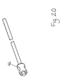
- the single carrier 92 can be replaced by a plurality of individual separate ferrules 96 (one of which is shown in Fig. 20), each of which is crimped to one of the flails 90a-90f, and which has a cross-sectional dimension larger than the cross-sectional dimension of the recess channels 72a-72f.
- Each ferrule 96 may comprise a simple hollow tube or may be split axially and thus have a C-shape in cross-section.
- a relatively uniform compressive load can be applied over the length of the ferrule 96 during the crimping process so that localized high stress on and weakening of the flail can be avoided.
- the individual ferrules 96 are placed in the recess center portion 74 with the flails extending outwardly through the aligned channels 72a-72f and 89a-89f.
- the ferrules 96 may be secured to the head by any suitable means (heat staking, adhesive, etc.), if desired.
- the ferrules prevent outward ejection of the flails 90a-90f owing to the difference in cross-sectional sizes of the ferrules and the channels 72a-72f.
- Crimping the flails to the carrier 92 or the individual ferrules 96 precludes the need to apply localized heat to the flails to secure the flails to the head 64, the carrier 92 or the ferrules 96, thereby avoiding heat induced local weakening and premature failure of the flails.
- an eject linkage 100 includes a button 102 which is accessible from a top surface 104 of the housing 22, and thus is remote from the head 64.
- First and second arms 106a, 106b slide in channels (not shown) or are otherwise guided by features in the housing 22 and include lower ends 108a, 108b which can be made to contact an upper flange surface 110 of the upper hub element 50.
- integral spring elements of the eject linkage 100 may bear against features (not shown) internal to the housing to bias the button 102 upwardly such that the lower ends 108a, 108b of the arms 106a, 106b are spaced from the upper hub element 50 when no pressure is applied to the button 102.
- an operator may press on the button 102, thereby displacing the linkage 100 downwardly to contact and then displace the upper hub element 50.
- the fan blades 60 are able to slide through the slots 62 of the lower hub element 40 to permit such movement.
- the center portion 52 of the upper hub element 50 ultimately bears against upper cam surfaces 120a-120c (Figs. 11-14) of the finger portions 80a-80c of head 64 and causes the arms 76a-76c to deflect inwardly, thereby disengaging the hooked portions 86a-86c from the outer margins 38a-88c of the apertures 82a-82c.
- the head 64 then either may be ejected by further movement of upper hub elements 50 and/or may drop downwardly under the force of gravity from the lower hub element 40 to permit access to the flail assembly 90. Once the worn flail assembly has been replaced with a new flail assembly, the head 64 can be reinstalled on the lower hub element 40 in the manner previously described.
- the head 64 and attached flail assembly 90 are replaced together as a unit.
- the head 64 and flail assembly 90 are fabricated of inexpensive materials so that cost is minimized.
- the head 64 is positively retained on the lower hub member 40, and this positive retention is enhanced during operation of the string trimmer 20 owing to an increase of the latching forces by centrifugal forces acting on the arms 76a-76c.
- the lengths of all of the flails need not be equal.
- the flails 90b, 90d and 90f may be of a first length and the remaining flails 90a, 90c and 90e may be of a second length longer than the first. It is thought that by making the flail lengths unequal, cutting efficiency can be maximized over the total life of the flails. Specifically, before wear has occurred, the majority of the cutting is accomplished at the tips of the longer flails, which are moving at a relatively high linear speed. As wear occurs, the flails shorten, thereby decreasing linear tip speed. Eventually, the longer flails wear to the length of the shorter flails, thereby presenting a greater number of flail tips for cutting, at least in part compensating for the shorter flail length and consequent lower tip speed.
- the long and short flail lengths form a pattern which is symmetric with respect to the rotational axis of the head so that an unbalanced situation is avoided.
- Figs. 17-19 illustrate an alternative embodiment of the present invention, which may utilize the head 64 and the flail assembly 90 of the previous Figs.
- a button 150 having a button recess 151 is actuable from the top surface of the housing 22 (Fig. 1) and is engageable with an eject linkage in the form of an ejection pin 152 having a spring plate 153 welded or otherwise secured thereto.
- the spring plate 153 resides within the button recess 151.
- the ejection pin 152 extends through a hollow motor shaft 154 and a hollow axle 156 of a hub member 158 into an ejector member 160.
- the hollow motor shaft 154 is rigidly fixed to the hollow axle 156 by any suitable means such that the hub member 158 rotates together with the shaft 154.
- the ejection pin 152 is spring loaded by a spring 161 disposed between the spring plate 153 and an end of the motor shaft 154 and the ejector member 160 is fixed to the end of the ejection pin 152 and is moveable therewith.
- the hub member 158 includes fan blades 162 and a lower main surface 164 from which walls 166a-166f extend defining chambers 168a-168f, respectively, similar or identical to the walls 61a-61f and chambers 63a-63f of Figs. 4 and 6.
- a central aperture 170 located between the walls 166 extends through the base surface 164 into a cavity 172 in which the ejector member 160 is disposed.
- the button 150 includes one or more integral spring elements 171 (Fig. 19) which engage structures or other features (such as grooves in ribs) in the housing 22 to bias the button 150 upwardly and thus normally space a base surface 173 of the button recess 151 from the spring plate 153 when no force is applied to the button 150.
- the head 64 is prepared for installation by placing a flail assembly 90 in the channels 72a-72f and recess chamber 74 (Fig. 12). The head 64 then is assembled onto the hub member 158 by passing the arms 76a-76c into the central aperture until the hooked portions 86a-86c engage undercut channels 174a-174c formed in a wall 176 defining the periphery of the aperture 170 (see Figs. 18a-18c). At this time, the ejector member 160 is positioned between the hub element 158 and the head 64, as seen in Fig. 19.
- the head 64 is keyed against rotation by fitting of the outer periphery of the head 64 with the outer portions of the walls 166a-166f and by seating of the hooked portions 86a-86c with the undercut channels 174a-174c (the channels 174a-174c have a limited angular extent, as seen in Figs. 18b and 18c). Ejection of the head 64 from the hub element 158 is accomplished by downwardly displacing the button 150 and the ejection pin 152 against the bias provided by the spring elements 171 and the spring 161, in turn, displacing the ejector member 160 into engagement with the finger portions 80a-80c.
- the flail assembly 90 can be configured to include arms like the arms 76 so that the assembly 90 itself may be removably retained on the hub member 40 or 158 without the need for the head 64.
- the flails 90a-90f may instead be permanently attached directly to the head 64 itself by any suitable means, such as heat staking, ultrasonic welding, adhesive, etc.
- the entine head 64 is replaced when the flails 90a-90f are worn.
- the number of individual flails used may vary, and, in fact, one or more flails may extend outwardly from opposite sides of the head 64, if desired. Regardless of the attachment of the flails, such attachment can be accomplished using highly automated, rapid operations.
- the button 102 or 150 may be located in a different position, allowing the actuating force for the release mechanism to be applied in a different direction.
- Figs. 21-23 illustrate an alternative embodiment of the present invention, in which a conventional head 200 incorporating a bump feed mechanism and used, for example, on a string trimmer powered by a motive power source (such as a gas engine or an electric motor) disposed at an upper end of the string trimmer, is retrofitted to utilize one or more disposable components (such as the head 64) according to the present invention.
- the motive power source is connected through a drive cable or other drive mechanism 202 to the head 200.
- the head 200 includes a main hub element or member 204 mounted for rotation on the drive cable 202 and from which the usual bump feed components (such as a spool, spring and a ground engaging member) have been removed.
- the head may be that found on string trimmer Model No.
- An auxiliary hub element or member 212 includes a cylindrical central boss 213 which extends through a central cylindrical bore 214 of a release mechanism in the form of an ejector element or member 215.
- the central boss 213 is slightly smaller than the bore 214 so that the ejector element can move axially relative to the auxiliary hub member 212.
- One or more leaf springs 218 are captured between the auxiliary hub member 212 and the ejector member 215 and are retained in position by any suitable means.
- a flat head screw 219 extends through a central bore 220 of the auxiliary hub member 212 (the bore 220 is centered within and extends fully through the central boss 213) and the bore 214 of the ejector member 215 and is threaded into a threaded bore 222 in the drive shaft 202.
- the screw 219 includes an enlarged head which captures the members 212, 215 on the drive shaft 202 for rotation therewith.
- first and second ears 222, 223 extend through diametrically opposite apertures 224, 226, respectively, in the main hub member 204.
- the ears 222, 223, and thus the ejector member 215, are axially movable a short distance in the apertures 224, 226. During such movement, the ejector member 215 is guided on the auxiliary hub member 212 owing to the fit of the central boss 213 in the bore 214.
- auxiliary hub member 212 and the main hub member 204 may have interengaging features to cause the two members to rotate together during operation.
- the auxiliary hub member 212 includes a lower main surface 230, identical to the lower main surface 59, from which the walls 61a-61f extend to define the recesses 63a-63f.
- the apertures 82a-82c described previously also extend through the surface 230.
- the hooked portions 86a-86c of the arms 76a-76c engage the outer margins 88a-88c of the apertures 82a-82c in the auxiliary hub member 212.
- the ears 222, 223, and thus the ejector member 215 are downwardly axially displaced against the bias provided by the leaf springs 218, a lower surface 232 of the ejector member 215 contacts the arms 76a-76c, thereby moving such arms inwardly and releasing the hooked portions 86a-86c from the outer margins 88a-88c of the apertures 82a-82c and releasing the head 64 from the auxiliary hub member 212.
- a new flail assembly 90 may then be placed in the head 64 and the head 64 may be reassembled on the auxiliary hub member 212 as described above.
- the present invention is advantageous in that the flail assembly 90 or the head 64, when worn, can be easily removed and replaced with a new one.
- This replacement procedure is simple and does not require the user to necessarily invert the string trimmer to remove the head. Instead, the user need only press the button 102 or 150, allowing the head 64 to simply fall off of the hub member.
- the disposable elements i.e., the flail assembly and the head 64
- cutting efficiency over the entire life of the flails may be improved as compared with other designs which utilize either a single flail or a plurality of flails, all of the same length.
Landscapes
- Life Sciences & Earth Sciences (AREA)
- Environmental Sciences (AREA)
- Harvester Elements (AREA)
Description
- The present invention relates generally to lawn and garden implements, and more particularly to a head for a string trimmer.
- String trimmers long have beer used to cut vegetation, particularly in areas inaccessible by a lawn mower or other cutting device. Typically, a string trimmer utilizes one or more flexible flails, such as a string fabricated of a plastic polymer, which is retained within a head assembly. In most string trimmers, the head assembly includes a spool for storing a large quantity of flail (string) therein together with a feeding mechanism for feeding the flail into a cutting path. These feeding mechanisms may be of the bump-feed type, the inertial-feed type, or a type that utilizes an actuator that is operable to feed string when a button or lever is pushed.
- Prior to the advent of feeding mechanisms, string trimmers utilized a fixed length of strang, which was replaced manually once wear had occurred beyond a certain point. Because of the need to replace the flail frequently, it initially was believed that feeding mechanisms would provide a better alternative to the user, who thereby would not be faced with the inconvenience of manually replacing the string at frequent intervals. However, the stored string tends to tangle and become fouled, and in certain circumstances can become welded to itself, thereby preventing proper operation of the feeding mechanism. In addition, reloading the spool with a supply of fresh string can be a complicated process, not easily undertaken by the typical consumer.
- Patents disclosing string trimmers that utilize one or more replaceable flails include Doolittle et al. U.S. Patent No. 4,089,114, Jacyno et al. U.S. Patent No. 4,118,865, Rouse U.S. Patent No. 4,756,146 and Tuggle U.S. Patent No. 5,303,476. The above-identified Doolittle et al. '114 patent further discloses the use of a disposable tip member, which snap-fits into a rotatable truncated cone member and a strand is secured within the disposable tip member.
- A head for a string trimmer permits easy replacement of flails and does not suffer from the disadvantages of flail feeding mechanisms.
- More particularly, in accordance with one aspect of the present invention, a head assembly for a string trimmer includes a hub member rotatable about an axis, a head and at least one flail captured between the head and the hub member. A mounting member fixes the head on the hub member and a release mechanism is provided allowing a component of force parallel to the axis to release the head from the hub member.
- In accordance with a further aspect of the present invention, a head for a string trimmer includes a main body having a base surface and at least one wall extending from the base surface and defining a recess adapted to removably receive a flail therein. A mounting arm is carried by either said base surface or the at least one wall for mounting the head on the hub member.
- In accordance with another aspect of the present invention, a head assembly for a string trimmer includes a hub member rotatable about an axis. A head is also included having a base surface, a plurality of arms extending in a certain direction away from the base surface and engageable in apertures in the hub member to releasably retain the head on the hub member and walls extending in the certain direction and defining recess channels. Flails are disposed in the recess channels and a release mechanism is actuable to exert a component of force parallel to the axis to release the head from the hub member.
- In accordance with a still further aspect of the present invention, a removable flail assembly for a string trimmer includes a carrier and a plurality of flails permanently connected to the carrier.
- In accordance with yet another aspect of the present invention, a string trimmer cutting assembly includes a hub member, a flail carrier removably retained on the hub member and a plurality of flails secured to the carrier.
- The present invention eliminates the difficulties encountered with flail feeding mechanisms and further provides a simple, yet effective, arrangement of parts that facilitates replacement of worn elements.
-
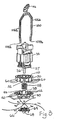
- Fig. 1 comprises a perspective view of a string trimmer incorporating the present invention;
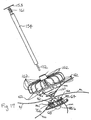
- Fig. 2 is an isometric view of a motor in conjunction with a release mechanism for releasing the head from the hub of the string trimmer;
- Fig. 3 is an exploded trimetric view of the elements of Fig. 2;
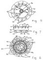
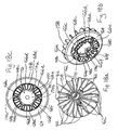
- Fig. 4 is a trimetric view taken from below the lower hub element of Fig. 3;
- Figs. 5-7 are plan, lower elevational and side elevational views, respectively, of the lower hub element of Fig. 4;
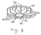
- Fig. 8 is a trimetric view, taken from below, of the upper hub element of Fig. 3;
- Figs. 9 and 10 are plan and side elevational views, respectively, of the upper hub element of Fig. 8;
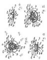
- Fig. 11 is an isometric view of the head of Fig. 3 in a first orientation;
- Fig. 12 is a plan view of the head of Fig. 11 in a second orientation which is rotated with respect to the first orientation;
- Pigs. 13 and 14 are side elevational views taken generally along the lines 13-13 and 14-14, respectively, of Fig. 12;
- Fig. 15 is an isometric view of a flail assembly for use with the head of Fig. 3;
- Fig. 16 is an enlarged trimetric view of the connection member of Fig. 15;
- Fig. 17 is a view similar to Fig. 3 illustrating an alternative embodiment of the present invention;
- Figs. 18a-18c are plan, bottom, isometric and bottom trimetric views of the hub member of Fig. 17;
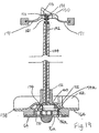
- Fig. 19 is a fragmentary sectional view of a portion of the embodiment illustrated in Fig. 17;
- Fig. 20 is an isometric view of a single ferrule and flail for use in an alternative embodiment of the present invention;
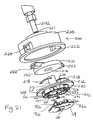
- Fig. 21 is a trimetric view of a further embodiment of the present invention;
- Fig. 22 is an exploded side elevational view of the embodiment of Fig. 21; and
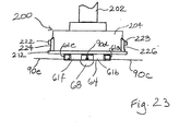
- Fig. 23 is a fragmentary side elevational view of the assembled components of Fig. 21.
-
- Referring first to Fig. 1, a string trimmer 20 includes a
motor housing 22 disposed at a first, lower end of aboom 24 and ahandle assembly 26 located at a second, upper end of theboom 24. As is conventional, ashield 28 is secured to thehousing 22 and a wire guard 30 is secured to one or both of thehousing 22 and theshield 28. The wire guard 30 prevents an operator from moving ahead assembly 32 closer than a certain distance to an object. The wire guard 30 may also be operable in a trimmer mode to serve as a guide. - Referring also to Figs. 2 and 3, a
motor 34 is disposed within thehousing 22 and is connected to electrical conductors (not shown) extending from thehandle assembly 26 through theboom 24 and into thehousing 22. The electrical conductors may be connected to a source of power to energize themotor 34, as is conventional. In a first embodiment of the present invention as illustrated in Figs. 2 and 3, a motor shaft 36 of themotor 34 is secured by any suitable means within abore 38 of a lower hub member orelement 40 so that theelement 40 is fixed to and rotates with the shaft 36 (theelement 40 is seen in greater detail in Figs. 4-7). An upper hub element 50 (shown in greater detail in Figs. 8-10) includes a centralcylindrical portion 52 having a bore 54 (Figs. 8 and 9) within which is slidingly received a centralhollow boss portion 56 of thelower hub element 40 such that theupper hub element 50 is captured between anend bell 57 of themotor 34 and thelower hub element 40. - Axial movement of the
upper hub element 50 can occur relative to thelower hub element 40, during which time theboss portion 56 slides within thebore 54. - A
spring 58 disposed between the upper andlower hub elements upper hub element 50 upwardly toward themotor 34 relative to thelower hub element 40. - The
upper hub element 50 includes a plurality offan blades 60 which provide air movement for cooling of themotor 34. Thefan blades 60 slidably engageslots 62 of thelower hub element 40 permitting axial travel ofupper hub element 50 while causing theupper hub element 50 to rotate with thelower hub element 40 and the motor shaft 36. - As seen in Figs. 4, 6 and 7, the
lower hub element 40 includes a lowermain surface 59 from whichwalls 61a-61f extend to define open chambers or recesses 63a-63f. - With reference also to Figs. 11-14, a
head 64 includes abase surface 66 which may be generally planar and a curvedlower member 68. Themember 68 is provided to space thehead 64 above the ground during operation. Thehead 64 further includes a plurality of upraised wall portions or sections 70a-70f, each of which is roughly triangular in shape and which together define a plurality ofrecess channels 72a-72f extending outwardly from arecess center portion 74. First through third mounting arms 76a-76c are carried by and extend away from thebase surface 66. If desired, each of the arms 76a-76c may instead be carried by acorresponding wall portion - When the
head 64 is mounted on thelower hub element 40, the finger portions 80a-80c extend intoapertures 82a-82c (Figs. 4-6), such thathooked portions 86a-86c (best seen in Figs. 11, 13, and 14) engage outer margins 88a-88c of theapertures 82a-82c, respectively (the outer margins 88a-88c are best seen in Figs. 5 and 6). Also, when thehead 64 is secured to thelower hub element 40, the wall portions 70a-70f fit within arecess center portion 87 of thelower hub element 40 and therecess channels 72a-72f are radially aligned with recess channels 89a-89f located betweenadjacent walls 61a-61f (see Figs. 4, 6 and 7). Therecess center portion 87 is defined by thewalls 61a-61f. - It should be noted that each of the finger portions 80a-80c may extend into any of the
apertures 82a-82c (i.e., the arms 76a-76c and theapertures 82a-82c are symmetric and hence may be aligned in any of three positions to fit thehead 64 onto thelower hub element 40.) - Fig. 15 illustrates a
flail assembly 90 which may be inserted into therecess channels 72a-72f and therecess center portion 74 prior to assembly of thehead 64 on thelower hub element 40. Theflail assembly 90 includes a plurality offlails 90a-90f which are secured to a central connection member orcarrier 92. As seen in Fig. 16, thecarrier 92 includes a plurality offlail receptacles 94a-94f in the form of ferrule members or portions which are crimped onto theflails 90a-90f, respectively, using any appropriate crimping tool. Thecarrier 92 may be fabricated of metal or any other suitable inexpensive material. If desired, thecarrier 92 may have a different shape and/or accommodate a different number of flails. - Once the
flail assembly 90 is assembled with thehead 64 and thelower hub element 40, thecarrier 92 is captured within one or both of therecess center portions recess channels 72a-72f and 89a-89f. - Rather than simply placing the
carrier 92 with attachedflails 90a-90f in therecess center portion 74, thecarrier 92 may instead be secured to thehead 64 inside theportion 74 by any suitable means, such as by heat staking, adhesive, etc. As a further alternative, thesingle carrier 92 can be replaced by a plurality of individual separate ferrules 96 (one of which is shown in Fig. 20), each of which is crimped to one of theflails 90a-90f, and which has a cross-sectional dimension larger than the cross-sectional dimension of therecess channels 72a-72f. Eachferrule 96 may comprise a simple hollow tube or may be split axially and thus have a C-shape in cross-section. In the latter case, a relatively uniform compressive load can be applied over the length of theferrule 96 during the crimping process so that localized high stress on and weakening of the flail can be avoided. Theindividual ferrules 96 are placed in therecess center portion 74 with the flails extending outwardly through the alignedchannels 72a-72f and 89a-89f. Theferrules 96 may be secured to the head by any suitable means (heat staking, adhesive, etc.), if desired. During rotation of thehead 64, the ferrules prevent outward ejection of theflails 90a-90f owing to the difference in cross-sectional sizes of the ferrules and thechannels 72a-72f. - Crimping the flails to the
carrier 92 or theindividual ferrules 96 precludes the need to apply localized heat to the flails to secure the flails to thehead 64, thecarrier 92 or theferrules 96, thereby avoiding heat induced local weakening and premature failure of the flails. - Referring again to Figs. 1, 2 and 3, an
eject linkage 100 includes abutton 102 which is accessible from atop surface 104 of thehousing 22, and thus is remote from thehead 64. First andsecond arms 106a, 106b slide in channels (not shown) or are otherwise guided by features in thehousing 22 and includelower ends 108a, 108b which can be made to contact anupper flange surface 110 of theupper hub element 50. If desired, integral spring elements of theeject linkage 100 may bear against features (not shown) internal to the housing to bias thebutton 102 upwardly such that the lower ends 108a, 108b of thearms 106a, 106b are spaced from theupper hub element 50 when no pressure is applied to thebutton 102. - When it is desired to replace a worn flail assembly, an operator may press on the
button 102, thereby displacing thelinkage 100 downwardly to contact and then displace theupper hub element 50. During such displacement, thefan blades 60 are able to slide through theslots 62 of thelower hub element 40 to permit such movement. Thecenter portion 52 of theupper hub element 50 ultimately bears againstupper cam surfaces 120a-120c (Figs. 11-14) of the finger portions 80a-80c ofhead 64 and causes the arms 76a-76c to deflect inwardly, thereby disengaging thehooked portions 86a-86c from the outer margins 38a-88c of theapertures 82a-82c. Thehead 64 then either may be ejected by further movement ofupper hub elements 50 and/or may drop downwardly under the force of gravity from thelower hub element 40 to permit access to theflail assembly 90. Once the worn flail assembly has been replaced with a new flail assembly, thehead 64 can be reinstalled on thelower hub element 40 in the manner previously described. - In those cases in which the
flail carrier 92 is secured to thehead 64, thehead 64 and attachedflail assembly 90 are replaced together as a unit. Preferably, thehead 64 andflail assembly 90 are fabricated of inexpensive materials so that cost is minimized. - Because the
hooked portions 86a-86c are biased outwardly into contact with the outer margins 88a-88c, thehead 64 is positively retained on thelower hub member 40, and this positive retention is enhanced during operation of the string trimmer 20 owing to an increase of the latching forces by centrifugal forces acting on the arms 76a-76c. - As should be evident from an inspection of Fig. 15, the lengths of all of the flails need not be equal. In fact, for example, the
flails flails - Preferably, the long and short flail lengths form a pattern which is symmetric with respect to the rotational axis of the head so that an unbalanced situation is avoided.
- Figs. 17-19 illustrate an alternative embodiment of the present invention, which may utilize the
head 64 and theflail assembly 90 of the previous Figs. In this embodiment, a button 150 having abutton recess 151 is actuable from the top surface of the housing 22 (Fig. 1) and is engageable with an eject linkage in the form of anejection pin 152 having aspring plate 153 welded or otherwise secured thereto. Thespring plate 153 resides within thebutton recess 151. Theejection pin 152 extends through ahollow motor shaft 154 and ahollow axle 156 of ahub member 158 into anejector member 160. Thehollow motor shaft 154 is rigidly fixed to thehollow axle 156 by any suitable means such that thehub member 158 rotates together with theshaft 154. Theejection pin 152 is spring loaded by aspring 161 disposed between thespring plate 153 and an end of themotor shaft 154 and theejector member 160 is fixed to the end of theejection pin 152 and is moveable therewith. As seen in Fig. 19 thehub member 158 includesfan blades 162 and a lowermain surface 164 from which walls 166a-166f extend defining chambers 168a-168f, respectively, similar or identical to thewalls 61a-61f and chambers 63a-63f of Figs. 4 and 6. Acentral aperture 170 located between the walls 166 extends through thebase surface 164 into acavity 172 in which theejector member 160 is disposed. - The button 150 includes one or more integral spring elements 171 (Fig. 19) which engage structures or other features (such as grooves in ribs) in the
housing 22 to bias the button 150 upwardly and thus normally space abase surface 173 of thebutton recess 151 from thespring plate 153 when no force is applied to the button 150. - As in the previous embodiment, the
head 64 is prepared for installation by placing aflail assembly 90 in thechannels 72a-72f and recess chamber 74 (Fig. 12). Thehead 64 then is assembled onto thehub member 158 by passing the arms 76a-76c into the central aperture until thehooked portions 86a-86c engage undercut channels 174a-174c formed in awall 176 defining the periphery of the aperture 170 (see Figs. 18a-18c). At this time, theejector member 160 is positioned between thehub element 158 and thehead 64, as seen in Fig. 19. Thehead 64 is keyed against rotation by fitting of the outer periphery of thehead 64 with the outer portions of the walls 166a-166f and by seating of thehooked portions 86a-86c with the undercut channels 174a-174c (the channels 174a-174c have a limited angular extent, as seen in Figs. 18b and 18c). Ejection of thehead 64 from thehub element 158 is accomplished by downwardly displacing the button 150 and theejection pin 152 against the bias provided by thespring elements 171 and thespring 161, in turn, displacing theejector member 160 into engagement with the finger portions 80a-80c. Continued downward displacement of theejector member 160 via the button 150 and theejection pin 152 causes the arms 76a-76c to deflect inwardly in the manner described previously, disengaging thehooked portions 86a-86c from the undercut channels 174a-174c. Thehead 64 thus is free to move away from thehub member 158, whether under the force of gravity, continued force applied by theejector member 160, or both. Thehead 64 then may be reloaded with anew flail assembly 90 and reassembled onto thehub member 158 in the manner previously described. - If desired, the
flail assembly 90 can be configured to include arms like the arms 76 so that theassembly 90 itself may be removably retained on thehub member head 64. - Also, if desired, the
flails 90a-90f may instead be permanently attached directly to thehead 64 itself by any suitable means, such as heat staking, ultrasonic welding, adhesive, etc. In this case, theentine head 64 is replaced when theflails 90a-90f are worn. The number of individual flails used may vary, and, in fact, one or more flails may extend outwardly from opposite sides of thehead 64, if desired. Regardless of the attachment of the flails, such attachment can be accomplished using highly automated, rapid operations. - In addition to the foregoing, by utilizing different ejector linkages, the
button 102 or 150 may be located in a different position, allowing the actuating force for the release mechanism to be applied in a different direction. - Figs. 21-23 illustrate an alternative embodiment of the present invention, in which a
conventional head 200 incorporating a bump feed mechanism and used, for example, on a string trimmer powered by a motive power source (such as a gas engine or an electric motor) disposed at an upper end of the string trimmer, is retrofitted to utilize one or more disposable components (such as the head 64) according to the present invention. The motive power source is connected through a drive cable orother drive mechanism 202 to thehead 200. Thehead 200 includes a main hub element ormember 204 mounted for rotation on thedrive cable 202 and from which the usual bump feed components (such as a spool, spring and a ground engaging member) have been removed. The head may be that found on string trimmer Model No. MAC2816, manufactured by McCulloch Corporation of Tucson, Arizona. An auxiliary hub element ormember 212 includes a cylindricalcentral boss 213 which extends through a centralcylindrical bore 214 of a release mechanism in the form of an ejector element ormember 215. Thecentral boss 213 is slightly smaller than thebore 214 so that the ejector element can move axially relative to theauxiliary hub member 212. One ormore leaf springs 218 are captured between theauxiliary hub member 212 and theejector member 215 and are retained in position by any suitable means. Aflat head screw 219 extends through acentral bore 220 of the auxiliary hub member 212 (thebore 220 is centered within and extends fully through the central boss 213) and thebore 214 of theejector member 215 and is threaded into a threadedbore 222 in thedrive shaft 202. Thescrew 219 includes an enlarged head which captures themembers drive shaft 202 for rotation therewith. As seen specifically in Fig. 23, first andsecond ears opposite apertures main hub member 204. Theears ejector member 215, are axially movable a short distance in theapertures ejector member 215 is guided on theauxiliary hub member 212 owing to the fit of thecentral boss 213 in thebore 214. - If desired, the
auxiliary hub member 212 and themain hub member 204 may have interengaging features to cause the two members to rotate together during operation. - The
auxiliary hub member 212 includes a lowermain surface 230, identical to the lowermain surface 59, from which thewalls 61a-61f extend to define the recesses 63a-63f. Theapertures 82a-82c described previously also extend through thesurface 230. - As in the previous embodiments, when the
head 64 is mounted on theauxiliary hub member 212, thehooked portions 86a-86c of the arms 76a-76c engage the outer margins 88a-88c of theapertures 82a-82c in theauxiliary hub member 212. When theears ejector member 215, are downwardly axially displaced against the bias provided by theleaf springs 218, alower surface 232 of theejector member 215 contacts the arms 76a-76c, thereby moving such arms inwardly and releasing thehooked portions 86a-86c from the outer margins 88a-88c of theapertures 82a-82c and releasing thehead 64 from theauxiliary hub member 212. Anew flail assembly 90 may then be placed in thehead 64 and thehead 64 may be reassembled on theauxiliary hub member 212 as described above. - The present invention is advantageous in that the
flail assembly 90 or thehead 64, when worn, can be easily removed and replaced with a new one. This replacement procedure is simple and does not require the user to necessarily invert the string trimmer to remove the head. Instead, the user need only press thebutton 102 or 150, allowing thehead 64 to simply fall off of the hub member. The disposable elements (i.e., the flail assembly and the head 64) are manufactured of inexpensive components and replacement thereof can be accomplished in a short period of time. Disadvantages associated with the use of flail feeding mechanisms are not encountered, and hence consumer satisfaction is enhanced. This is particularly important, keeping in mind that the single greatest reason for return of string trimmers to the manufacturer is tangled flails in the flail feeding mechanism. - In addition to the foregoing, cutting efficiency over the entire life of the flails may be improved as compared with other designs which utilize either a single flail or a plurality of flails, all of the same length.
- Numerous modifications to the present invention will be apparent to those skilled in the art in view of the foregoing description. Accordingly, this description is to be construed as illustrative only and is presented for the purpose of enabling those skilled in the art to make and use the invention and to teach the best mode of carrying out same. The exclusive rights of all modifications which come within the scope of the appended claims are reserved.
Claims (24)
- A head assembly for a string trimmer, comprising:a hub member (40;158;212) rotatable about an axis;a head (64); anda mounting member (76a-76c) fixing the head of the hub member; characterized in that:at least one flail (90a) is captured between the head (64) and the hub member (40;158;212),and in that a release mechanism allows a component of force parallel to the axis to release the head from the hub member.
- The head assembly of claim 1, wherein the mounting member comprises an arm (76a) carried by the head.
- The head assembly of claim 1, wherein the release mechanism comprises an ejector member (52;160;215) and an eject linkage (100;152;222).
- The head assembly of claim 3, wherein the hub member (158) is driven by a motor having a hollow motor shaft (154) and wherein the eject linkage (152) extends through the hollow motor shaft (154).
- The head assembly of claim 3, wherein the hub member (40) is driven by a motor (34) and wherein the eject linkage (100) extends around the motor (34).
- The head assembly of claim 1, wherein the release mechanism is actuable by a button (102;150) remote from the head (64).
- The head assembly of claim 6, wherein the hub member is driven by a motor (34) located in a housing (22) and wherein the button (102) is disposed on a top surface (104) of the string trimmer.
- The head assembly of claim 1, wherein a plurality of flails (90a-90f) are captured between the hub member (40;158;212) and the head (64).
- The head assembly of claim 8, wherein the plurality of flails (90a-90f) are mounted to a carrier member (92).
- The head assembly of claim 9, wherein the carrier member (92) is disposed in a recess (74) in the head (64).
- The head assembly of claim 8, wherein one (90d) of the flails has a length different than a length of another of the flails.
- The head assembly of claim 8, wherein each of a first set of flails (90a,90c,90e) has a first length and each of a second set of flails (90b,90d,90f) has a second length different than the first length.
- The head assembly of claim 1, wherein six flails (90a-90f) are captured between the head (64) and the hub member (40;158;212).
- The head assembly of claim 13, wherein each of a first set of flails has a first length and each of a second set of flails has a second length different than the first length.
- The head assembly of claim 8, wherein the plurality of flails (90a-90f) are directly and substantially permanently secured to the head (64).
- The head assembly of claim 8, wherein each flail (90a-90f) is secured to an individual ferrule (94a-94f).
- The head assembly of claim 1, wherein the mounting member comprises a plurality of arms (76a-76c) extending in a certain direction away from a base surface (66) of the head (64), the plurality of arms (76a-76c) being engageable in apertures (82a-82c) in the hub member (40), said head (64) further including walls (70a-70f) extending in the certain direction and defining recess channels (72a-72f) and wherein a plurality of flails (90a-90f) are disposed in the recess channels (72a-72f).
- The head assembly of claim 17, wherein the release mechanism includes a release actuator (102;150) remote from the head (64).
- The head assembly of claim 17, wherein the recess channels (72a-72f) extend outwardly from a recess center portion (74) and wherein the flails (90a-90f) are joined together by a carrier (92) disposed in the recess center portion (74).
- A head (64) for a string trimmer, comprising:characterized in that a mounting arm (76a) is carried by either said base surface (66) or the at least one wall (70b) for mounting the head (64) on a hub member (40).a main body having a base surface (66); andat least one wall (70b) extending from the base surface (66) and defining a recess (72b,74) adapted to removably receive a flail (76b) therein;
- The head of claim 20, including further mounting arms (76b,76c) wherein the mounting arms are spaced from one another.
- The head of claim 20, including further walls (70a,70c-70f) extending from the base surface (66) wherein the at least one wall (70b) and the further walls define a plurality of recess channels (72a-72f) extending from a recess center portion (74).
- The head of claim 22, in combination with a flail portion (90a-90f) extending through each of the recess channels (72a-72f).
- The head of claim 23, further including a carrier member (92) to which the flail portions (90a-90f) are mounted wherein the carrier member (92) is disposed in the recess center portion (74).
Applications Claiming Priority (2)
| Application Number | Priority Date | Filing Date | Title |
|---|---|---|---|
| US899471 | 1986-08-22 | ||
| US08/899,471 US5987756A (en) | 1997-07-23 | 1997-07-23 | Head and head assembly for a string trimmer |
Publications (2)
| Publication Number | Publication Date |
|---|---|
| EP0893046A1 EP0893046A1 (en) | 1999-01-27 |
| EP0893046B1 true EP0893046B1 (en) | 2003-03-19 |
Family
ID=25411047
Family Applications (1)
| Application Number | Title | Priority Date | Filing Date |
|---|---|---|---|
| EP98401867A Expired - Lifetime EP0893046B1 (en) | 1997-07-23 | 1998-07-22 | Head an head assembly for a string trimmer |
Country Status (4)
| Country | Link |
|---|---|
| US (1) | US5987756A (en) |
| EP (1) | EP0893046B1 (en) |
| CA (1) | CA2243867C (en) |
| DE (1) | DE69812240T2 (en) |
Families Citing this family (34)
| Publication number | Priority date | Publication date | Assignee | Title |
|---|---|---|---|---|
| USD446699S1 (en) | 1999-08-12 | 2001-08-21 | Black & Decker, Inc. | String trimmer |
| US7111403B2 (en) | 1999-09-21 | 2006-09-26 | Moore Mark R | Head for line trimming apparatus |
| US6401344B1 (en) | 1999-09-21 | 2002-06-11 | Mark R. Moore | Head for line trimming apparatus |
| US20020029483A1 (en) * | 2000-08-11 | 2002-03-14 | Price Joseph E. | Multipurpose rotary cutting tool having interchangeable heads |
| AU147221S (en) | 2000-11-28 | 2002-03-21 | Black & Decker Inc | A trimmer |
| AU147222S (en) | 2000-11-28 | 2002-03-21 | Black & Decker Inc | A trimmer |
| WO2003020008A1 (en) * | 2001-09-03 | 2003-03-13 | Speed France | Cutting wire for brush cutters and edge trimmers |
| FR2850239B1 (en) * | 2003-01-23 | 2005-10-21 | Speed France | CUTTING HEAD FOR BRUSHCUTTER, CUTTER OR SIMILAR |
| FR2850235B1 (en) * | 2003-01-23 | 2005-10-21 | Speed France | CUTTING HEAD FOR BRUSHCUTTER, CUTTER OR SIMILAR |
| FR2850236B1 (en) * | 2003-01-23 | 2005-10-21 | Speed France | BRUSHCUTTER, CUTTER OR SIMILAR CUTTING HEAD |
| FR2850238B1 (en) * | 2003-01-23 | 2005-10-21 | Speed France | CUTTING HEAD FOR BRUSHCUTTER, CUTTER OR SIMILAR |
| FR2850237B1 (en) * | 2003-01-23 | 2005-10-21 | Speed France | CUTTING HEAD FOR BRUSHCUTTER, CUTTER OR SIMILAR |
| FR2854764B1 (en) | 2003-05-14 | 2006-06-23 | Speed France | NEW CUTTING WIRE FOR APPARATUS SUCH AS TRIMMERS OR BRUSHCUTTERS |
| WO2005074668A1 (en) * | 2004-01-09 | 2005-08-18 | Speed France | Cutting head for bush cutter, hedge cutter or the like provided with improved means for locking a cutting wire |
| WO2005077143A1 (en) | 2004-01-19 | 2005-08-25 | Speed France | Method for the production of plant cutting filaments and plant cutting filaments |
| USD510512S1 (en) | 2004-03-24 | 2005-10-11 | Black & Decker Inc. | String trimmer |
| FR2881022B1 (en) * | 2005-01-24 | 2007-04-06 | Speed France Sa | IMPROVED COMPOSITION CUTTING FILAMENT FOR CUTTERS, BRUSHCUTTERS, ETC. |
| USD552436S1 (en) * | 2005-08-19 | 2007-10-09 | Black & Decker Inc. | String trimmer |
| USD550525S1 (en) * | 2006-06-23 | 2007-09-11 | Robert Bosch Gmbh | Grass and weed cutter |
| US7536792B2 (en) | 2007-01-03 | 2009-05-26 | Moore Mark R | Head for a rotary line trimmer apparatus |
| US8060284B2 (en) * | 2007-10-31 | 2011-11-15 | Deere & Company | Work machine with torque limiting control for an infinitely variable transmission |
| US8176639B2 (en) * | 2009-05-14 | 2012-05-15 | Doane Ian J | Filament clamp for a vegetation trimmer |
| US20110203118A1 (en) * | 2010-02-19 | 2011-08-25 | Kyodo Co., Ltd. | Brush cutter |
| US20120159790A1 (en) | 2010-12-22 | 2012-06-28 | Hoelscher Gene | Grass trimming apparatus with spinning support guide |
| US9056381B1 (en) * | 2011-07-12 | 2015-06-16 | Frank L. Airosa | Line trimmer/grinder system |
| USD714108S1 (en) * | 2013-06-20 | 2014-09-30 | Black & Decker Inc. | String trimmer |
| US9472992B2 (en) * | 2013-07-11 | 2016-10-18 | The Toro Company | Electric motor support structure and power equipment unit incorporating same |
| US10485165B2 (en) * | 2014-11-25 | 2019-11-26 | Chervon (Hk) Limited | Grass trimmer |
| AU2015101710A4 (en) | 2014-11-25 | 2015-12-24 | Nanjing Chervon Industry Co., Ltd. | Grass Trimmer |
| WO2016126547A1 (en) | 2015-02-06 | 2016-08-11 | Mtd Products Inc | Handheld lawn maintenance tool |
| US10070582B2 (en) | 2016-04-20 | 2018-09-11 | Tti (Macao Commercial Offshore) Limited | String trimmer head |
| USD830798S1 (en) * | 2016-06-03 | 2018-10-16 | Andreas Stihl Ag & Co. Kg | Battery powered trimmer |
| EP4110035B1 (en) * | 2020-02-27 | 2024-02-21 | T&I Consulting AB | Trimmer head |
| USD1075938S1 (en) * | 2023-05-11 | 2025-05-20 | Audioec Inc. | String trimmer bubble toy |
Family Cites Families (42)
| Publication number | Priority date | Publication date | Assignee | Title |
|---|---|---|---|---|
| US3895440A (en) * | 1974-10-15 | 1975-07-22 | Jr Charles B Pittinger | Disk for filament trimmer |
| US4043103A (en) * | 1976-03-15 | 1977-08-23 | Lakin George W | Lawn edger accessory |
| US4062114A (en) * | 1976-05-07 | 1977-12-13 | Woodrow Wilson Luick | Vegetation cutting apparatus |
| US4086700A (en) * | 1976-07-13 | 1978-05-02 | Elta Machine Industrial Co., Ltd. | Cutting head for a mower |
| CA1079075A (en) * | 1976-07-19 | 1980-06-10 | George C. Ballas | Rotary cutting assembly |
| US4656739A (en) * | 1976-08-10 | 1987-04-14 | Pittinger Jr Charles B | Bump-feed filament vegetation trimmer |
| US4089114A (en) * | 1976-08-31 | 1978-05-16 | Disston, Inc. | Cutting device |
| US4524515A (en) * | 1976-10-18 | 1985-06-25 | The Toro Company | Rotary cutting assembly with filament feed |
| US4118865A (en) * | 1977-01-14 | 1978-10-10 | Mcgraw-Edison Company | Assembly for removably attaching flexible cutting line element in grass trimmer |
| US4852258A (en) * | 1981-03-19 | 1989-08-01 | White Consolidated Industries, Inc. | Apparatus for cutting vegetation |
| DE2826280A1 (en) * | 1978-06-15 | 1979-12-20 | Peter Sick | Rotary brush for mechanism fruit cropping - has relatively long bristle tufts of strong smooth plastics e.g. polyethylene or PTFE |
| DE2828425A1 (en) * | 1978-06-28 | 1980-01-10 | Stihl Maschf Andreas | PLANT CUTTER |
| US4203212A (en) * | 1978-07-13 | 1980-05-20 | Proulx Raymond E | Flail feedout mechanism for a rotary mower |
| US4189833A (en) * | 1978-08-15 | 1980-02-26 | Weed Eater, Inc. | Apparatus for cutting vegetation |
| US4268964A (en) * | 1979-07-02 | 1981-05-26 | Ambac Industries, Incorporated | Apparatus for cutting, trimming and edging vegetation and the like |
| US4271595A (en) * | 1979-07-26 | 1981-06-09 | Hawaiian Motor Company | Housing and cutting line assembly for vegetation cutting apparatus |
| US4250623A (en) * | 1979-08-01 | 1981-02-17 | Pittinger Charles B | Filament vegetation trimmer |
| US4259782A (en) * | 1979-09-14 | 1981-04-07 | Proulx Raymond E | Flail feedout mechanism for a rotary mower |
| US4476623A (en) * | 1979-10-22 | 1984-10-16 | International Business Machines Corporation | Method of fabricating a bipolar dynamic memory cell |
| US4295324A (en) * | 1980-06-30 | 1981-10-20 | Corinco, Inc. | Balanced mower head for carrying a plurality of monofilament lines |
| US4412382A (en) * | 1981-05-04 | 1983-11-01 | The Toro Company | Line feed mechanism for filament cutting |
| JPS6083508A (en) * | 1983-10-15 | 1985-05-11 | タナカ工業株式会社 | Nylon cord type mower |
| US4550498A (en) * | 1984-02-17 | 1985-11-05 | Oliver Ronald A | Replacement spool for rotating line vegetation cutter |
| US4571831A (en) * | 1984-07-31 | 1986-02-25 | The Toro Company | Cutting head for filament trimmer |
| US4685279A (en) * | 1986-01-17 | 1987-08-11 | Gullett Bradley T | Weed trimmer |
| US4738085A (en) * | 1986-04-22 | 1988-04-19 | Starting Industry Company Limited | Rotary cutter for mowers |
| US4823465A (en) * | 1986-12-17 | 1989-04-25 | White Consolidated Industries, Inc. | Line feed mechanism for line trimmers |
| US4790071A (en) * | 1987-01-02 | 1988-12-13 | Trimrite, Inc. | Line trimmer with replaceable cutting blade assembly |
| US4756146A (en) * | 1987-02-18 | 1988-07-12 | Snapper Power Equipment Division Of Fuqua Industries, Inc. | String trimmer head and method |
| US4779405A (en) * | 1987-05-01 | 1988-10-25 | Piston Powered Products, Inc. | Line-feeding head for a rotary line trimmer |
| JPH0455472Y2 (en) * | 1987-10-06 | 1992-12-25 | ||
| CA1319018C (en) * | 1987-11-04 | 1993-06-15 | Maria Rosa Calcinai | Appliance for scrub clearance, grass cutting or the like, with devices for lengthening the cutting line and coupling devices |
| US4794695A (en) * | 1988-01-04 | 1989-01-03 | Hurst Hubert L | Easy loading herbage trimmer |
| US4819416A (en) * | 1988-02-17 | 1989-04-11 | The Unblade Co. | Rotary cutting member for use with lawnmowers and the like |
| US5109607A (en) * | 1990-10-12 | 1992-05-05 | Inertia Dynamics Corporation | Automatic line trimmer head |
| US5197264A (en) * | 1991-05-21 | 1993-03-30 | Paul Lacey | Universal filament trimmer cutting head |
| US5303476A (en) * | 1992-10-29 | 1994-04-19 | Wci Outdoor Products, Inc. | Line head for a rotary line trimmer |
| US5398416A (en) * | 1994-01-03 | 1995-03-21 | Mackey; Robert T. | Universal string trimmer replacement head |
| US5433006A (en) * | 1994-01-28 | 1995-07-18 | Komatsu Zenoah Company | Mowing apparatus |
| JP3167859B2 (en) * | 1994-04-07 | 2001-05-21 | タナカ工業株式会社 | Nylon cord type brush cutter |
| US5493785A (en) * | 1994-12-12 | 1996-02-27 | Lawrence; Elbert | Rotary grass cutting head |
| US5651418A (en) * | 1995-04-17 | 1997-07-29 | Jerez; Orlando | Convertible, user-supported, garden cleaning implement for cutting/macerating weeds and like |
-
1997
- 1997-07-23 US US08/899,471 patent/US5987756A/en not_active Expired - Fee Related
-
1998
- 1998-07-22 DE DE69812240T patent/DE69812240T2/en not_active Expired - Fee Related
- 1998-07-22 CA CA002243867A patent/CA2243867C/en not_active Expired - Fee Related
- 1998-07-22 EP EP98401867A patent/EP0893046B1/en not_active Expired - Lifetime
Also Published As
| Publication number | Publication date |
|---|---|
| EP0893046A1 (en) | 1999-01-27 |
| DE69812240D1 (en) | 2003-04-24 |
| CA2243867A1 (en) | 1999-01-23 |
| CA2243867C (en) | 2006-09-19 |
| US5987756A (en) | 1999-11-23 |
| DE69812240T2 (en) | 2003-12-18 |
Similar Documents
| Publication | Publication Date | Title |
|---|---|---|
| EP0893046B1 (en) | Head an head assembly for a string trimmer | |
| US6094823A (en) | Method and apparatus for anchoring flails on a string trimmer | |
| US6401344B1 (en) | Head for line trimming apparatus | |
| EP2319288B1 (en) | String head for a trimmer | |
| US4524515A (en) | Rotary cutting assembly with filament feed | |
| US4476632A (en) | Multiple flail head for a rotary mower | |
| US7111403B2 (en) | Head for line trimming apparatus | |
| US4274201A (en) | Rotary cutting assembly with filament feed | |
| US9861033B2 (en) | Universally adaptable, easy to load trimmer head with free rotating bump knob | |
| EP0943228B1 (en) | Fixed-line trimmer head | |
| US4685279A (en) | Weed trimmer | |
| US5615543A (en) | Rotary cutting head | |
| US4068376A (en) | Flexible cutting line and rotor therefor | |
| US5713191A (en) | Monofilament line based cutter assembly | |
| CN222090177U (en) | String trimmer components | |
| US6418627B1 (en) | Rotary cutter of mower | |
| US6735874B2 (en) | Cutting head for a rotary trimmer | |
| US20090100686A1 (en) | Fixed-line rotary head for string trimmer machine | |
| WO1999004611A1 (en) | Fixed line trimmer head | |
| WO2008137061A1 (en) | Top unloading fixed line trimmer head | |
| US20130152359A1 (en) | Rotary trimmer apparatus and related rotary head assembly | |
| US20070084061A1 (en) | Mechanism for attaching trimmer line strips to a head of a trimming apparatus | |
| US4290257A (en) | Rotary assembly for cutting grass and other vegetation | |
| US12342753B2 (en) | Rotator, brush cutter, and bobbin | |
| CN219893861U (en) | Mower cutting mechanism convenient to dismantle blade |
Legal Events
| Date | Code | Title | Description |
|---|---|---|---|
| PUAI | Public reference made under article 153(3) epc to a published international application that has entered the european phase |
Free format text: ORIGINAL CODE: 0009012 |
|
| AK | Designated contracting states |
Kind code of ref document: A1 Designated state(s): DE FR GB IT |
|
| AX | Request for extension of the european patent |
Free format text: AL;LT;LV;MK;RO;SI |
|
| AKX | Designation fees paid | ||
| 17P | Request for examination filed |
Effective date: 19990920 |
|
| RBV | Designated contracting states (corrected) |
Designated state(s): AT BE CH CY LI |
|
| RBV | Designated contracting states (corrected) |
Designated state(s): DE FR GB IT |
|
| REG | Reference to a national code |
Ref country code: DE Ref legal event code: 8566 |
|
| 17Q | First examination report despatched |
Effective date: 20011205 |
|
| GRAH | Despatch of communication of intention to grant a patent |
Free format text: ORIGINAL CODE: EPIDOS IGRA |
|
| GRAH | Despatch of communication of intention to grant a patent |
Free format text: ORIGINAL CODE: EPIDOS IGRA |
|
| GRAA | (expected) grant |
Free format text: ORIGINAL CODE: 0009210 |
|
| RAP1 | Party data changed (applicant data changed or rights of an application transferred) |
Owner name: AB ELECTROLUX |
|
| RIN1 | Information on inventor provided before grant (corrected) |
Inventor name: REDDING, GLENN K. Inventor name: SMITH, ROGER W. Inventor name: KRAMER, GREGORY S. Inventor name: KRULL, MICHAEL Inventor name: SEARLE, JOHN F. Inventor name: LIND, JAMES Inventor name: TREES, GREGORY A Inventor name: YATES, JAN B. |
|
| AK | Designated contracting states |
Designated state(s): DE FR GB IT |
|
| REG | Reference to a national code |
Ref country code: GB Ref legal event code: FG4D |
|
| REF | Corresponds to: |
Ref document number: 69812240 Country of ref document: DE Date of ref document: 20030424 Kind code of ref document: P |
|
| ET | Fr: translation filed | ||
| PLBE | No opposition filed within time limit |
Free format text: ORIGINAL CODE: 0009261 |
|
| STAA | Information on the status of an ep patent application or granted ep patent |
Free format text: STATUS: NO OPPOSITION FILED WITHIN TIME LIMIT |
|
| 26N | No opposition filed |
Effective date: 20031222 |
|
| PGFP | Annual fee paid to national office [announced via postgrant information from national office to epo] |
Ref country code: FR Payment date: 20040708 Year of fee payment: 7 |
|
| PGFP | Annual fee paid to national office [announced via postgrant information from national office to epo] |
Ref country code: GB Payment date: 20040721 Year of fee payment: 7 |
|
| PGFP | Annual fee paid to national office [announced via postgrant information from national office to epo] |
Ref country code: DE Payment date: 20040729 Year of fee payment: 7 |
|
| PG25 | Lapsed in a contracting state [announced via postgrant information from national office to epo] |
Ref country code: IT Free format text: LAPSE BECAUSE OF NON-PAYMENT OF DUE FEES Effective date: 20050722 Ref country code: GB Free format text: LAPSE BECAUSE OF NON-PAYMENT OF DUE FEES Effective date: 20050722 |
|
| PG25 | Lapsed in a contracting state [announced via postgrant information from national office to epo] |
Ref country code: DE Free format text: LAPSE BECAUSE OF NON-PAYMENT OF DUE FEES Effective date: 20060201 |
|
| GBPC | Gb: european patent ceased through non-payment of renewal fee |
Effective date: 20050722 |
|
| PG25 | Lapsed in a contracting state [announced via postgrant information from national office to epo] |
Ref country code: FR Free format text: LAPSE BECAUSE OF NON-PAYMENT OF DUE FEES Effective date: 20060331 |
|
| REG | Reference to a national code |
Ref country code: FR Ref legal event code: ST Effective date: 20060331 |