EP0892573A2 - Communication method and communication system - Google Patents
Communication method and communication system Download PDFInfo
- Publication number
- EP0892573A2 EP0892573A2 EP98110976A EP98110976A EP0892573A2 EP 0892573 A2 EP0892573 A2 EP 0892573A2 EP 98110976 A EP98110976 A EP 98110976A EP 98110976 A EP98110976 A EP 98110976A EP 0892573 A2 EP0892573 A2 EP 0892573A2
- Authority
- EP
- European Patent Office
- Prior art keywords
- path
- repeating
- request
- subchannels
- installations
- Prior art date
- Legal status (The legal status is an assumption and is not a legal conclusion. Google has not performed a legal analysis and makes no representation as to the accuracy of the status listed.)
- Withdrawn
Links
- 238000004891 communication Methods 0.000 title claims abstract description 253
- 238000000034 method Methods 0.000 title claims description 26
- 238000009434 installation Methods 0.000 claims abstract description 221
- 230000005540 biological transmission Effects 0.000 claims description 58
- 230000000694 effects Effects 0.000 claims description 18
- 238000010586 diagram Methods 0.000 description 12
- 230000007704 transition Effects 0.000 description 8
- 230000005236 sound signal Effects 0.000 description 3
- 101100388212 Arabidopsis thaliana DSP3 gene Proteins 0.000 description 2
- 101150052726 DSP2 gene Proteins 0.000 description 2
- 101150115013 DSP1 gene Proteins 0.000 description 1
- JEIPFZHSYJVQDO-UHFFFAOYSA-N ferric oxide Chemical compound O=[Fe]O[Fe]=O JEIPFZHSYJVQDO-UHFFFAOYSA-N 0.000 description 1
- 238000012544 monitoring process Methods 0.000 description 1
- 238000004904 shortening Methods 0.000 description 1
- 230000001360 synchronised effect Effects 0.000 description 1
Images


Classifications
-
- H—ELECTRICITY
- H04—ELECTRIC COMMUNICATION TECHNIQUE
- H04L—TRANSMISSION OF DIGITAL INFORMATION, e.g. TELEGRAPHIC COMMUNICATION
- H04L12/00—Data switching networks
- H04L12/28—Data switching networks characterised by path configuration, e.g. LAN [Local Area Networks] or WAN [Wide Area Networks]
- H04L12/42—Loop networks
- H04L12/427—Loop networks with decentralised control
- H04L12/43—Loop networks with decentralised control with synchronous transmission, e.g. time division multiplex [TDM], slotted rings
-
- H—ELECTRICITY
- H04—ELECTRIC COMMUNICATION TECHNIQUE
- H04B—TRANSMISSION
- H04B1/00—Details of transmission systems, not covered by a single one of groups H04B3/00 - H04B13/00; Details of transmission systems not characterised by the medium used for transmission
- H04B1/06—Receivers
- H04B1/16—Circuits
- H04B1/20—Circuits for coupling gramophone pick-up, recorder output, or microphone to receiver
- H04B1/205—Circuits for coupling gramophone pick-up, recorder output, or microphone to receiver with control bus for exchanging commands between units
Definitions
- the present invention relates to a communication system which is arranged by connecting plural repeating installations connected with one or more node terminals via a data transmission line and exchange data between the node terminals, between the repeating installations or between the node terminals and repeating installations, more specifically, for example, relates to a communication method and communication system which can securely transmit communication data from an originating source node terminal to a specified destination node terminal without reducing a data transmission amount per unit time.
- a communication system which is arranged such that plural repeating installations respectively connected with one or more node terminals are connected with each other via a data transmission line and exchanges data between the node terminals, between the repeating installations or between the node terminals and repeating installations, has been generally known.
- the central managing device connected with the communication system always monitors use/free state of plural data channels provided respectively to the repeating installations. At this time, for example, when a certain node terminal connected with a certain repeating installation makes a request of transmission of communication data, accordingly the repeating installation sends use request of data channels to the central managing device.
- the central managing device successively searches plural communication paths from an originating source node terminal to a destination node terminal for data channels in free state or in free-enabled state, and allocates the searched data channel to the repeating installation sending use request.
- communication paths from the originating source node terminal to the destination node terminal are secured, and communication data can be transmitted securely from the originating source node terminal to the destination node terminal along the communication paths.
- the central managing device in the case where data are exchanged between the node terminals, every time a certain node terminal connected with a certain repeating installation make a request of transmission of communication data, the repeating installation connected with this node terminal transmits use request of data channels to the central managing device. Accordingly the central managing device successively searches plural communication paths from the originating node terminal to the destination node terminal for data channels in free state or in free-enabled state, and allocates the searched data channels to the repeating installation which made use request. Since the central managing device should perform such a complicated process, time required for securing the usable communication paths becomes comparatively longer. Therefore, there arises a problem to be solved such that it is difficult to increase a data transmission amount per unit time in the communication system.
- the present invention has been achieved with such points in view. It therefore is an object of the present invention to provide a communication method and communication system which can transmit communication data from an originating source node terminal to a specified destination node terminal securely without reducing a data transmission amount per unit time even in the case where data are exchanged between node terminals belonging respectively to different repeating installations by reducing load due to path management in the respecting repeating installations and by shortening processing time required for the path management in the respective repeating installations.
- a first aspect of the invention provides a communication method which is used in a communication system arranged by connecting plural repeating installations, to which one or more node terminals are connected, via a data transmission line, when data are exchanged between the node terminals, between the repeating installations or between the node terminals and repeating installations, the communication method comprising the steps of:
- the path request repeating installation transmits a number of request subchannels which are used occupationally by the communication data to be transmitted to all multiple destination repeating installations existing in paths from the originating source to destination in multiple way, whereas the respective multiple destination repeating installations, which received the number of request subchannels from the path request repeating installation, refer to the received number of request subchannels and the path information stored in the path information storage measure so as to manage respective communication paths respectively. Therefore, load due to the path management in the respective repeating installations is reduced, and processing time required for the path management in the repeating installations is shortened.
- the communication data can be transmitted from the originating source node terminal to the specified destination node terminal securely without reducing a data transmission amount per unit time.
- a second aspect of the present invention provide a communication method according to claim 1, further comprising the steps of:
- the respective multiple destination repeating installations which received the number of request subchannels from the path request repeating installation refer to the received number of request subchannels and, the path information stored in the path information storage measure so as to judge as to whether or not a requested number of subchannels can be prepared, and return the result of the preparation YES/NO judgment to the path request repeating installation.
- a third aspect of the present invention provides a communication method according to claim 1, further comprising the steps of:
- the respective multiple destination repeating installations which received the number of request subchannels from the path request repeating installation refer to the received number of request subchannels and the path information stored in the path information storage measure so as to judge as to whether or not a requested number of subchannels can be prepared, and when the judgment is made that a requested number of subchannels cannot be prepared as the result of the preparation YES/NO judgment, return the state that subchannels cannot be prepared to the path request repeating installation. Therefore, the path request repeating installation, which received the state that subchannels cannot be prepared, can grasp all that the preparation impossible states in each multiple destination repeating installation.
- a fourth aspect of the present invention provides a communication method which is used in a communication system arranged by connecting plural repeating installations, to which one or more node terminals are connected, via a data transmission line, when data are exchanged between the node terminals, between the repeating installations or between the node terminals and repeating installations, the communication method comprising the steps of:
- the path request repeating installation transmits a number of request subchannels which are used occupationally by the communication data to be transmitted to all multiple destination repeating installations existing in paths from the originating source to destination in multiple way
- the respective multiple destination repeating installations which received the number of request subchannels from the path request repeating installation refer to the received number of request subchannels and the path information stored in the path information storage measure so as to judge as to whether or not the requested number of subchannels can be prepared, and when the judgment is made that the requested number of subchannels can be prepared as the result of the preparation YES/NO judgment, return the effect that the preparation for receiving the communication data is completed to the path request repeating installation.
- the path request repeating installation which received the effect that the preparation for receiving the communication data is completed from all the multiple destination repeating installations, transmits declaration to use a new path number obtained by performing prescribed operation on the maximum path number stored in the path information storage measure to at least all the multiple destination repeating installations in multiple way.
- paths for the communication data from the originating source to destination with use-declared new path number can be secured, and path numbers, which are eigenvalues for respective communication data whose source is the same, are given to the secured communication paths in order to be able to discriminate the communication data whose sources are different from each other. Therefore, transferring per communication path, starting-up, stopping, etc. are simplified per path number, and as a result, easiness and expandability of the path management can be improved greatly.
- a fifth aspect of the present invention provides a communication method according to claim 4, further comprising the step of:
- the respective multiple destination repeating installations which received the new path number use declaration from the path request repeating installation, rewrite and update the maximum path number stored in the path information storage measure into the received new path number.
- a sixth aspect of the present invention provides a communication system comprising plural repeating installations, to which one or more node terminals are connected, connected via a data transmission line, the communication system exchanging data between the node terminals, between the repeating installations or between the node terminals and repeating installations, the plural repeating installations comprising:
- the request subchannel number multiple transmission measure of the path request repeating installation transmits a number of request subchannels which are used occupationally by the communication data to be transmitted to all multiple destination repeating installations existing in paths from the originating source to destination in multiple way
- a path control measure which is provided respectively to the respective multiple destination repeating installations which received the number of request subchannels from the path request repeating installation, refers to the received number of request subchannels and the path information stored in the path information storage measure so as to manage respective communication paths respectively. Therefore, processing load due to the path management in the repeating installations is reduced, and processing time required for the path management in the repeating installation is shortened.
- the communication data can be transmitted from the originating source node terminal to the specified destination node terminal securely without reducing a data transmission amount per unit time.
- a seventh aspect of the present invention provides a communication system according to claim 6, wherein the path control circuit judges as to whether or not the requested number of subchannels can be prepared with referring to the received number of request subchannels and path information stored in the path information storage circuit, and returns a result of a preparation YES/NO judgment to the path request repeating installation.
- the path control measure which is provided respectively to the multiple destination repeating installations which received the number of request subchannels from the path request repeating installation, refers to the received number of request subchannels and path information stored in the path information storage measure so as to judge as to whether or not the requested number of subchannels can be prepared, and returns the result of the preparation YES/NO judgment to the path request repeating installation.
- an eighth aspect of the present invention provides a communication system according to claim 6, wherein the path control circuit judges as to whether or not the requested number of subchannels can be prepared with referring to the received number of request subchannels and path information stored in the path information storage circuit, and returns a preparation impossible condition to the path request repeating installation when a judgment is made that the requested number of subchannels cannot be prepared as a result of a preparation YES/NO judgment.
- the path control measure which is provided respectively to the multiple destination repeating installations received the number of request subchannels from the path request repeating installation, refers to the received number of request subchannels and path information stored in the path information storage measure so as to judge as to whether or not the requested number of subchannels can be prepared, and when the judgment is made that the requested number of subchannels cannot be prepared as the result of the preparation YES/NO judgment, returns the preparation impossible condition to the path request repeating installation. Therefore, the path request repeating installation received the preparation impossible condition can grasp all the preparation impossible conditions in the respective multiple destination repeating installations.
- a ninth aspect of the present invention provides a communication system comprising plural repeating installations, to which one or more node terminals are connected, connected via a data transmission line, the communication system exchanging data between the node terminals, between the repeating installations or between the node terminals and repeating installations, the plural repeating installations comprising:
- the request subchannel number multiple transmission measure of the path request repeating installation transmits a number of request subchannels which are used occupationally by the communication data to be transmitted to all multiple destination repeating installations existing in paths from the originating source to destination in multiple way
- the path control measure which is provided respectively in the respective multiple destination repeating installations, which received the number of request subchannels from the path request repeating installation, refers to the received number of request subchannels and the path information stored in the path information storage measure so as to judge as to whether or not the requested number of subchannels can be prepared and when the judgment is made that the requested number of subchannels can be prepared as the result of the preparation YES/NO judgment, returning the effect that the preparation for receiving the communication data is completed to the path request repeating installation.
- the use declaration multiple transmission measure in the path request repeating installation which received the effect that the preparation for receiving the communication data is completed from all the multiple destination repeating installations, transmits declaration to use a new path number obtained by performing prescribed operation on the maximum path number stored in the path information storage measure to at least all the multiple destination repeating installations in multiple way.
- paths for the communication data from the originating source to destination with use-declared new path number can be secured, and path numbers, which are eigenvalues for respective communication data whose source is the same, are given to the secured communication paths in order to be able to discriminate the communication data whose sources are different from each other. Therefore, transferring per communication path, starting-up, stopping, etc. are simplified per path number, and as a result, easiness and expandability of the path management can be improved greatly.
- a tenth aspect of the present invention provides a communication system according to claim 9, wherein the multiple destination repeating installations which received the new path number use declaration from the path request repeating installation, comprises a path number rewriting/updating circuit for rewriting and updating a maximum path number stored in the path information storage circuit into the received new path number.
- the path number rewriting/updating measure which is provided respectively in the multiple destination repeating installations which received the new path number use declaration from the path request repeating installation, rewrites and updates the maximum path number stored in the path information storage measure into the received new path number.
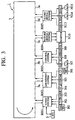
- a communication system 1 of the present invention is arranged such that plural route hubs RH1, RH2, RH3, RH4 and RH5 as repeating installations are connected via loop-formed data transmission lines 3 so that data can be exchanged therebetween.
- the route hub RH1 is connected with respective route hubs RH composing synchronous control in the whole communication system 1 and composing the communication system 1, and with a system control unit (SCU) 5 for generally managing an address setting operation, etc. of respective functional equipments N, mentioned later.
- SCU system control unit
- network topology of the communication system 1 besides the aforementioned loop form, for example, suitable forms such as bus form and star form can be adopted.
- the plural route hubs RH are connected respectively with one or more various functional equipments N1 through N15 as node terminals, and thus data can be exchanged between the route hubs RH, between the functional equipments N or between the functional equipments N and route hubs RH via the data transmission lines 3 which permits communication data to be transmitted to a direction of an arrow in FIG. 1, for example.
- Examples of the functional equipments N which can be adopted are a portable telephone, facsimile (FAX), digital TV, radio receiver, navigation unit (NV), vehicle-borne receiver (VICS) which receives vehicle information provided from a Vehicle Information and Communication System, a vehicle-borne communication device (ETC) which communicates toll information with an Electrical Toll Collection System for collecting toll of a toll road automatically, DVD (Digital Video Disc)-ROM unit, CD (Compact Disc)-ROM unit, DAT (Digital Audio Tape recorder), MD (mini Disc), audio amplifier containing a digital signal processor (DSP), CAN (Controller Area Network) interface, various sensors such as a bearing sensor and car speed sensor, monitor unit and vehicle-borne personal computer.
- the plural route hubs RH are divided per functional unit into a tuner system for inputting a radio wave from a facsimile (FAX), portable telephone, etc. and a broadcasting radio wave from a digital TV or radio receiver from the functional equipments N, an amusement system for inputting a sound signal and picture signal, information about traffic jam from the functional equipments N such as a navigation device (NV), a control system for inputting control information, etc. from the functional equipments N such as various sensors, a picture signal system for outputting a picture signal to a monitor unit, etc., and a sound signal system for outputting a sound signal to an audio amplifier, etc. containing a digital signal processor (DSP).
- DSP digital signal processor
- Inherent addresses are previously set respectively in the plural route hubs RH and functional equipments N by an address setting operation, for example, by the system control unit (SCU) 5 when the communication system 1 is turned on so that they can be discriminated from each other. These addresses are used for specifying a destination or originating source in the case where data are exchanged between the route hubs RH, between the functional equipments N or between the functional equipments N and route hubs RH via the data transmission line 3.
- SCU system control unit
- the route hub RH3 is arranged so as to include a network input interface (hereinafter, "interface” is abbreviated as "I/F") 7, a network buffer 9, a network output I/F 11, an equipment input I/F 13, a path control section 15, a path information storage section 17 and an equipment output I/F 19.
- interface hereinafter, "interface” is abbreviated as "I/F”
- network buffer 9 a network output I/F 11
- an equipment input I/F 13 an equipment input I/F 13
- path control section a path control section
- path information storage section 17 a path information storage section
- the path control section 15 is connected with the various functional equipments N7, N8 and N9 connected with the route hub RH3 via a communication line 23, and is connected with an operation control unit 21 which always monitors and inputs operation information relating to operating states of the various functional equipments N7, N8 and N9 so as to transmit the inputted operation information to the path control section 15, whereas inputs the operation information of the various functional equipments N7, N8 and N9 transmitted from the path control section 15 so as to distribute and transmit the inputted operation information to the various functional equipments N7, N8 and N9.
- the network input I/F 7 inputs various instructions and operation information of the functional equipments N, or communication data including source data, etc. or communication data transmitted from the equipment input I/F 13, mentioned later, which are transmitted from the route hub RH2 positioned on the upper stream side via a data transmission line 3b, and distributes and outputs the inputted communication data to a suitable transmission destination.
- the network buffer 9 temporarily stores the communication data inputted via the network input I/F 7.
- the network output I/F 11 transmits the communication data transmitted from the network buffer 9 or path control section 15 to the route hub RH4 positioned on the lower stream side via a data transmission line 3c.
- the equipment input I/F 13 has first through third input ports P1, P2 and P3, and it inputs the communication data transmitted from the functional equipments N8 and N9 connected with the equipment input I/F 13 via the first through third input ports P1, P2 and P3, performs suitable converting process on the inputted communication data so as to transmit the converted communication data to the network input I/F 7.
- the path information storage section 17 suitably refers to the operation information of the various functional equipments N7, N8 and N9 inputted from the operation control unit 21 and at the same time always updates path information, mentioned later, to be in the latest state so as to store the path information.
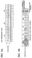
- the path information of the route hub RH3 stored in the path information storage section 17, as shown in FIGs. 6A and 6B, comprises use/free states of twenty-four subchannels S1 through S24, path numbers and maximum path number.
- the subchannels S1 through S24 are allocated every time when the communication data inputted/outputted into/from the route hub RH3 are received (Rx)/transmitted (Tx) and which are composed by dividing three channels CH1, CH2 and CH3 respectively into eight, for example.
- the maximum path number is a maximum value of the path numbers being used in the communication system 1.
- the path control section 15 comprises:
- the equipment output I/F 19 has three first through third output ports P4, P5 and P6, and it inputs the communication data transmitted from the network output I/F 11, and performs a suitable converting process on the inputted communication data so as to distribute and output the converted communication data to the functional equipment N7 via the specified fourth output port P4 in the first through third output ports P4, P5 and P6.
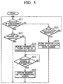
- the operation of the respective route hubs RH is described by typically exemplifying the route hub RH3 on reference to the operation flow charts shown in FIGs. 4 and 5.
- the description refers to the case where the route hub RH3 or one of the functional equipments N8 and N9 to be an originating source node terminal in the various functional equipments N7, N8 and N9 connected with the route hub RH3 requests transmission of the communication data to a prescribed destination, namely, the route hub RH3 is a path request route hub RH, and the case where the other route hubs make path request.
- route hub RH3 is described by exemplifying the case where the route hub RH3 is a path request route hub RH.
- the path control section 15 transmits a number of request subchannels which are used occupationally by a group of communication data to be transmitted to the network output I/F 11, and accordingly the network output I/F 11 transmits a number of request subchannels in multiple way to all the route hubs RH existing in paths from the originating source to destination as multiple destination (Step S1).
- the path control section 15 judges as to whether or not it received self path information including numbers of paths in use from the multiple destination route hubs RH via the network input I/F 7 (Step S3).
- the multiple destination route hubs RH which received a number of request subchannels from the path request route hub RH, as mentioned later, judges as to whether or not the route hubs RH themselves can prepare a requested number of subchannels, and as the result of the preparation YES/NO judgment, when the judgment is made that the route hubs RH themselves cannot prepare a requested number of subchannels, the self path information of the route hubs RH themselves is returned to the path request route hub RH.
- all pieces of the self path information of the route hubs RH which cannot prepare a requested number of subchannels are obtained in the route hub RH3 as the path request route hub RH so that a condition that a requested number of subchannels cannot be prepared in the route hubs RH, namely, an insufficient number of subchannels, for example, can be grasped respectively.
- the path control section 15 judges as to whether or not it received the effect that the route hub RH which originates the self path information can prepare a requested number of subchannels, namely, judges as to whether or not the preparation for receiving the communication data is completed (Step S5), and repeats the judgment at S5 until the preparation for receiving the communication data is completed in all the multiple destination route hubs RH.
- the multiple destination route hubs RH which returns the self path information to the path request route hub RH, as mentioned later, monitors as to whether or not a sufficient requested number of subchannels are free.
- the multiple destination route hubs RH When as a result of the monitoring of free channels, when a sufficient requested number of subchannels are free, the multiple destination route hubs RH returns the effect that the route hubs RH themselves can prepared a requested number of subchannels to the path request route hub RH, so according to the receiving preparation completion judgment at S5, the path request route hub RH can grasp as to whether or not the preparation for receiving the communication data in all the multiple destination route hubs RH is completed.
- the path control section 15 transmits use declaration of a new path number, which are obtained by performing a prescribed operation on the maximum path number stored in the path information storage section 17, more specifically, for example, the new path number, which is obtained by increasing the maximum path number stored in the path information storage section 17 by "1", to the network output I/F 11, and accordingly the network output I/F 11 transmits the new path number use declaration to all the route hubs RH other than the multiple destination route hub in multiple way (Step S7).
- the multiple destination route hubs RH which received the use declaration of the new path number from the path request route hub RH, as mentioned later, rewrites so as to update the maximum path number stored in the path information storage section 17 into the received new path number, and describes the new path number in a prescribed subchannel which is a free area at the time of the completion of the preparation for receiving.
- the path request route hub RH can secure new paths for the communication data from the originating source to destination.
- the route hubs RH other than the multiple destinations, which received the new path umber use declaration from the path request route hub RH rewrites so as to update the maximum path number stored in the path information storage section 17 into the received new path number.
- the following describes the operation of the route hub RH3 by exemplifying the case where the route hub RH3 receives the path request from the route hubs RH other than the route hub RH3.
- the path control section 15 judges as to whether or not it received a number of request subchannels when the route hub RH3 is multiple destinations from the path request route hub RH (Step S11).
- the path control section 15 refers to the received number of request subchannels and path state of the subchannels in the self path information stored in the path information storage section 15 so as to judge as to whether or not the route hub RH3 can prepare for a requested number of subchannels (Step S13).
- the path control section 15 transmits the self path information including the numbers of paths in use to the network output I/F 11, and accordingly the network output I/F 11 returns the self path information to the path request route hub RH (Step S15).
- the route hub RH3 can be arranged so as to return insufficient number of subchannels to the path request route hub RH, for example.
- the route hub RH3 as multiple destination can be arranged so as to return the maximum path number in the numbers of paths in use to the path request route hub RH regardless of as to whether or not a requested number of subchannels can be prepared.
- the path control section 15 monitors as to whether or not a sufficient number of subchannels are free so as to judge as to whether or not the preparation for receiving the communication data is completed (Step S17) and repeats the preparation YES/NO judgment at S17 until a sufficient number of subchannels are free.
- the path control section 15 can make the preparation YES/NO judgment at S17.
- the path control section 15 transmits the effect that the preparation for receiving the communication data is completed to the network output I/F 11, and accordingly the network output I/F 11 returns the effect that the preparation for receiving the communication data is completed to the path request route hub RH (Step S19).
- the path control section 15 makes a path declaration reception YES/NO judgment as to whether or not the path control section 15 received new path number use declaration from the path request route hub RH (Step S21), and repeats the path declaration reception YES/NO judgment at S21 until the path control section 15 receives the new path number use declaration.
- the path control section 15 rewrites so as to update the maximum path number stored in the path information storage section 17 into the received new path number, and describes the new path number in a prescribed subchannel as a free area at the time of the completion of the preparation for receiving (Step S23).
- the route hub RH3 can secure paths for communication data originated from the path request route hub RH.
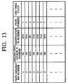
- the plural path request route hubs RH1, RH2 and RH5 shown in FIG. 13 successively request paths for communication data, and the path numbers "1", "2" and "3" are given to the respective request paths.
- the description is given as to the procedure for securing paths by exemplifying the case where the route hub RH1 requests paths for communication data from the originating source functional equipment N3 to the destination functional equipment N15.
- the route hub RH1 specifies the route hubs RH2, RH3, RH4 and RH5 as multiple destinations, and transmits "6", for example, as a number of request subchannels to the multiple destinations in multiple way.
- the route hub RH1 receives responses as to whether or not a requested number of subchannels can be prepared from all the multiple destinations, and judges as to whether or not preparation for the paths for communication data is completed in the respective multiple destinations based on the received result.
- the route hub RH1 transmits new path number use declaration, in which the new path number is an operation value "1" obtained by increasing a maximum path number initially set for "0" when the communication system 1 is powered on by a prescribed value such as "1", to the multiple destinations in multiple way.
- the path for communication data from the originating source functional equipment N3 to the destination functional equipment N15 is secured with use-declared new path number "1".
- a path for communication data in which the functional equipment N3 (radio) connected with the route hub RH1 is an originating source and the functional equipment N15 (DSP3) connected with the route hub RH5 is a destination is secured with the path number 1 ⁇ .
- a path for communication data in which the functional equipment N6 (CD/DAT/MD) connected with the route hub RH2 is an originating source and the functional equipment N14 (DSP2) connected with the route hub RH5 is a destination is secured with the path number 2 ⁇ .
- a path for communication data in which the functional equipment N13 (sensor 2) connected with the route hub RH5 is an originating source and the functional equipment N7 (DSP1) connected with the route hub RH3 is a destination is secured with the path number 3 ⁇ .
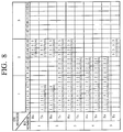
- FIG. 8 shows a list of the path state of subchannels in the respective route hubs RH corresponding to the path connected state shown in FIG. 7.
- the path number "1" is described in the subchannels S1 through S6 on the transmission side (Tx) of the route hub RH1
- the path number "1" is described in the subchannels S1 through S6 on the receiving side (Rx) and transmission side (Tx) of the route hubs RH2, RH3 and RH4
- the path number "1" is described in the subchannels S1 through S6 on the receiving side (Rx) of the route hub RH5.
- path number "2" is described in the subchannels S7 through S12 on the transmission side (Tx) of the route hub RH2
- path number "2" is described in the subchannels S7 through S12 on the receiving side (Rx) and transmission side (Tx) of the route hubs RH3 and RH4
- path number "2" is described in the subchannels S7 through S12 on the receiving side (Rx) of the route hub RH5.
- path number "3" is described in the subchannels S13 through S16 on the transmission side (Tx) of the route hub RH5
- path number "3" is described in the subchannels S13 through S16 on the receiving side (Rx) and transmission side (Rx) of the route hubs RH1 and RH2
- path number "3" is described in the subchannels S13 through S16 on the receiving side (Rx) of the route hub RH3.
- the respective route hubs RH use occupationally subchannels with the the same number respectively for the plural groups of communication data.
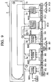
- a path for communication data with path number 4 ⁇ in which the functional equipment N9 (sensor 1) connected with the route hub RH3 is an originating source and the functional equipment N10 (monitor) connected with the route hub RH4 is a destination, is secured as a communication path for two systems newly generated.
- a path for communication data with path number 5 ⁇ in which the functional equipment N8 (CAN) connected with the route hub RH3 is an originating source and the functional equipment N10 (monitor) connected with the route hub RH4 is a destination, is secured.
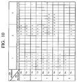
- FIG. 10 shows a list of the path state of the subchannels in the respective route hubs RH corresponding to the path connected state shown in FIG. 9.
- the communication paths corresponding to the path numbers 1 ⁇ and 3 ⁇ are held in that state, and the path state in FIG. 8 is held in the same state. Therefore, the description relating to the communication paths corresponding to the path numbers 1 ⁇ and 3 ⁇ are omitted, and the description is given as to the path state of the subchannels in the respective route hubs RH for securing the communication path for two system newly generated.
- path number "4" is described in the subchannels S13 through S16 on the transmission side (Tx) of the route hub RH3
- path number "4" is described in the subchannels S13 through S16 on the receiving side (Rx) of the route hub RH4.
- path number "4" is described in the subchannels S13 through S16 on the transmission side (Tx) of the route hub RH3
- path number "4" is described in the subchannels S13 through S16 on the receiving side (Rx) of the route hub RH4.
- FIG. 10 shows that the subchannels corresponding to path number 2 ⁇ , which become a free area after the communication is completed in the example of FIG. 7 are not used, and subchannels whose numbers are the same as the subchannels used occupationally by path number 3 ⁇ and are a free area are used.
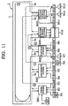
- a path for communication data of path number 6 ⁇ in which the functional equipment N3 (radio) connected with the route hub RH1 is an originating source and the functional equipment N14 (DSP2) connected with the route hub RH5 is a destination, is secured as the communication path for two systems newly originated, and a path for communication data with path number 6 ⁇ , in which the functional equipment N6 (CD/DAT/MD) connected with the route hub RH2 is an originating source and the functional equipment N15 (DSP3) connected with the route hub RH5 is a destination, is secured.
- the functional equipment N6 CD/DAT/MD
- FIG. 12 shows a list of the path state of the subchannels in the respective route hubs RH corresponding to the path connected state shown in FIG. 11.
- the communication paths corresponding path numbers 3 ⁇ , 4 ⁇ and 5 ⁇ are held intact, and the path state of FIG. 10 is kept in the same state. Therefore, the description relating to the communication paths corresponding to path numbers 3 ⁇ , 4 ⁇ and 5 ⁇ is omitted, and the description is given as to the path state of the subchannels in the respective route hubs RH for securing communication paths 6 ⁇ and 7 ⁇ for two systems newly generated.
- path number "6" is described in the subchannels S1 through S6 on the transmission side (Tx) of the route hub RH1
- path number "6” is described in the subchannels S1 through S6 on the receiving side (Rx) and transmission side (Tx) of the route hubs RH2, RH3 and RH4
- path number "6" is described in the subchannels S1 through S6 on the receiving side (Rx) of the route hub RH5.
- path number "7” is described in the subchannels S7 through S12 on the transmission side (Tx) of the route hub RH2
- path number "7” is described in the subchannels S7 through S12 on the receiving side (Rx) and transmission side (Tx) of the route hubs RH3 and RH4
- path number "7” is described in the subchannels S7 through S12 on the receiving side (Rx) of the route hub RH5.
- FIG. 12 shows that the subchannels S1 through S12, which become a free area after the communication in the example of FIG. 7 or 9 is completed, are used by the communication paths 6 ⁇ and 7 ⁇ for two systems newly originated.
- the multiple destination route hubs RH which received a number of request subchannels from the path request route hub RH and received the path number use declaration, can respectively refer to the path state of their subchannels so as to describe path numbers declared to be used in a free area of arbitrary subchannels. Namely, the multiple destination route hubs RH can make the path management therein individually and dispersively.
- path request route hub RH which makes path request, first transmits a number of request subchannels to multiple destinations which are route hubs RH existing in paths from the originating source to destination. Next, the path request route hub RH receives responses as to whether or not a requested number of subchannels can be prepared from all the multiple destinations, and judges as to whether or not the preparation for paths for communication data is completed in the respective multiple destinations based on the received results.
- the path request route hub RH transmits in multiple way new path number use declaration, in which a new path number is an operation value obtained by increasing the maximum path number stored in the path information storage section 17 by a prescribed number such as "1", to all the route hubs RH other than the multiple destinations.
- a new path number is an operation value obtained by increasing the maximum path number stored in the path information storage section 17 by a prescribed number such as "1"
- the paths for communication data from the originating source to destination with new path number can be secured.
- the path request route hub which makes path request, transmits a number of request subchannels to multiple destinations which are route hubs RH existing from the originating source to destination in multiple way, whereas the route hubs RH as the multiple destinations makes communication path management individually and dispersively so as to obtain a requested number of subchannels. Therefore, processing load due to the path management in the respective route hubs RH is reduced, and processing time required for the path management in the route hubs RH is shortened. As a result, even in the case where data are exchanged between the functional equipments belonging respectively to different route hubs RH, for example, communication data can be transmitted securely from the originating source to destination without lowering a data transmission amount per unit time.
- the path request route hub RH which makes path request, secures communication paths from originating source to destination, and path numbers, which are eigenvalues for individual communication data originated from the same source are given, are given to the obtained communication paths in order to discriminate the communication data originated from different sources from each other. Therefore, transferring, starting-up, stopping, etc. per communication path are simplified, and as a result, easiness and expandability of the path management can be improved greatly.
- the path request route hub RH which makes path request, transmits in multiple way a number of request channels to multiple destinations which are route hubs RH existing from originating source to destination, whereas the respective multiple destination route hubs RH makes the communication path management individually and dispersively in order to obtain a requested number of subchannels, but in the case where a requested number of subchannels cannot be prepared, an insufficient number of channels and or self path information is returns to the path request route hub RH. Therefore, the path request route hub RH can grasp the state that a requested number of subchannels cannot be prepared in each multiple destination route hub RH.
- the plural route hubs RH can respectively perform the dispersed path management, and when transmitting the effect that plural sets of communication paths are switched simultaneously to multiple destinations, the plural sets of communication paths can be switched simultaneously.
- the central path management can be made simply similarly to the dispersive path management.
- the respective route hubs RH occupies subchannels with the same numbers corresponding to the respective groups of communication data.
- the present invention is not limited to this embodiment, so in order to plural groups of communication data from the originating source to destination, the present invention can be also applied to embodiment such that the respective route hubs RH successively occupy subchannels with different numbers for respective groups of communication data in such a manner that the subchannels are occupied starting from a left part of free area.
Landscapes
- Engineering & Computer Science (AREA)
- Computer Networks & Wireless Communication (AREA)
- Signal Processing (AREA)
- Data Exchanges In Wide-Area Networks (AREA)
- Small-Scale Networks (AREA)
Abstract
Description
Claims (10)
- A communication method which is used in a communication system arranged by connecting plural repeating installations, to which one or more node terminals are connected, via a data transmission line, when data are exchanged between the node terminals, between the repeating installations or between the node terminals and repeating installations, said communication method comprising the steps of:providing the plural repeating installations with plural subchannels which become paths for communication data received/transmitted from/to the respective repeating installations and path information storage circuit for storing path information relating to paths from an originating source to destination per subchannel;transmitting, from a repeating installation in the plural repeating installations, which becomes a path request repeating installation when request of transmission of communication data is made to a prescribed destination in one of the repeating installation itself or a node terminal connected with the repeating installation itself, a number of request subchannels which are used occupationally by the communication data to be transmitted to all multiple destination repeating installations existing in paths from the originating source to destination in multiple way; andreferring, in the respective multiple destination repeating installations which received the number of request subchannels from the path request repeating installation, to the received number of request subchannels and the path information stored in the path information storage circuit to manage respective communication paths respectively.
- A communication method according to claim 1, further comprising the steps of:judging, in the respective multiple destination repeating installations which received the number of request subchannels from the path request repeating installation, as to whether or not a requested number of subchannels can be prepared with referring to the received number of request subchannels and the path information stored in the path information storage circuit; andreturning a result of a preparation YES/NO judgment from the respective multiple destination repeating installations to the path request repeating installation.
- A communication method according to claim 1, further comprising the steps of:judging, in the respective multiple destination repeating installations which received the number of request subchannels from the path request repeating installation, as to whether or not a requested number of subchannels can be prepared with referring to the received number of request subchannels and the path information stored in the path information storage circuit; andreturning a state that subchannels cannot be prepared to the path request repeating installation when a judgment is made that a requested number of subchannels cannot be prepared as a result of the preparation YES/NO judgment.
- A communication method which is used in a communication system arranged by connecting plural repeating installations, to which one or more node terminals are connected, via a data transmission line, when data are exchanged between the node terminals, between the repeating installations or between the node terminals and repeating installations, the communication method comprising the steps of:providing the plural repeating installations with plural subchannels which become paths for communication data received/transmitted from/to the respective repeating installations, and path information storage circuit for storing path information which comprises use/free state of the subchannels, path numbers to which eigenvalues are given for communication data whose sources are the same in order to be able to discriminate communication data whose sources are different from each other and maximum path number which is one of the path numbers in use in the communication system obtains a maximum value;transmitting, from a repeating installation in the plural repeating installations, which becomes a path request repeating installation when request of transmission of communication data is made to a prescribed destination in one of the repeating installation itself or a node terminal connected with the repeating installation itself, a number of request subchannels which are used occupationally by the communication data to be transmitted to all multiple destination repeating installations existing in paths from an originating source to destination in multiple way;judging, in the respective multiple destination repeating installations which received the number of request subchannels from the path request repeating installation, as to whether or not the requested number of subchannels can be prepared with referring to the received number of request subchannels and the path information stored in the path information storage circuit;returning an effect that the preparation for receiving the communication data is completed to the path request repeating installation when a judgment is made that the requested number of subchannels can be prepared as a result of a preparation YES/NO judgment; andtransmitting, from the path request repeating installation which received an effect that a preparation for receiving the communication data is completed from all the multiple destination repeating installations, declaration to use a new path number obtained by performing prescribed operation on a maximum path number stored in the path information storage circuit to at least all the multiple destination repeating installations in multiple way.
- A communication method according to claim 4, further comprising the step of:rewriting and updating, in the respective multiple destination repeating installations which received a new path number use declaration from the path request repeating installation, a maximum path number stored in the path information storage circuit into the received new path number.
- A communication system comprising plural repeating installations, to which one or more node terminals are connected, connected via a data transmission line, said communication system exchanging data between the node terminals, between the repeating installations or between the node terminals and repeating installations, said plural repeating installations comprising:plural subchannels which become paths for communication data received/transmitted from/to the respective repeating installations; anda path information storage circuit for storing path information relating to paths from an originating source to destination per subchannel;a repeating installation in said plural repeating installations, which becomes a path request repeating installation when request of transmission of communication data is made to a prescribed destination in one of the repeating installation itself or a node terminal connected with the repeating installation itself: comprisinga request subchannel number multiple transmission circuit for transmitting a number of request subchannels which are used occupationally by the communication data to be transmitted to all multiple destination repeating installations existing in paths from an originating source to destination in multiple way;said respective multiple destination repeating installations which received the number of request subchannels from the path request repeating installation: comprisinga path control circuit for referring to the received number of request subchannels and the path information stored in the path information storage circuit so as to manage respective communication paths respectively.
- A communication system according to claim 6, wherein said path control circuit judges as to whether or not the requested number of subchannels can be prepared with referring to the received number of request subchannels and path information stored in the path information storage circuit, and returns a result of a preparation YES/NO judgment to the path request repeating installation.
- A communication system according to claim 6, wherein the path control circuit Judges as to whether or not the requested number of subchannels can be prepared with referring to the received number of request subchannels and path information stored in the path information storage circuit, and returns a preparation impossible condition to the path request repeating installation when a judgment is made that the requested number of subchannels cannot be prepared as a result of a preparation YES/NO judgment.
- A communication system comprising plural repeating installations, to which one or more node terminals are connected, connected via a data transmission line, said communication system exchanging data between the node terminals, between the repeating installations or between the node terminals and repeating installations, said plural repeating installations comprising:plural subchannels which become paths for communication data received/transmitted from/to the respective repeating installations; anda path information storage circuit for storing path information which comprises use/free state of the subchannels, path numbers to which eigenvalues are given for communication data whose sources are the same in order to be able to discriminate communication data whose sources are different from each other and maximum path number which is one of the path numbers in use in the communication system obtains a maximum value;a repeating installation in said plural repeating installations, which becomes a path request repeating installation when request of transmission of communication data is made to a prescribed destination in one of the repeating installation itself or a node terminal connected with the repeating installation itself: comprisinga request subchannel number multiple transmission circuit for transmitting a number of request subchannels which are used occupationally by the communication data to be transmitted to all multiple destination repeating installations existing in paths from an originating source to destination in multiple way;said respective multiple destination repeating installations which received the number of request subchannels from the path request repeating installation, comprising:a path control circuit for referring to the received number of request subchannels and the path information stored in the path information storage circuit so as to judge as to whether or not the requested number of subchannels can be prepared and when the judgment is made that the requested number of subchannels can be prepared as a result of a preparation YES/NO judgment, returning the effect that the preparation for receiving the communication data is completed to the path request repeating installation;said path request repeating installation which received an effect that a preparation for receiving the communication data is completed from all the multiple destination repeating installations, comprising:a use declaration multiple transmission circuit for transmitting declaration to use a new path number obtained by performing prescribed operation on a maximum path number stored in the path information storage circuit to at least all the multiple destination repeating installations in multiple way.
- The communication system according to claim 9, wherein the multiple destination repeating installations which received the new path number use declaration from the path request repeating installation, comprises a path number rewriting/updating circuit for rewriting and updating a maximum path number stored in the path information storage circuit into the received new path number.
Applications Claiming Priority (6)
| Application Number | Priority Date | Filing Date | Title |
|---|---|---|---|
| JP15890797 | 1997-06-16 | ||
| JP15890797 | 1997-06-16 | ||
| JP158907/97 | 1997-06-16 | ||
| JP208134/97 | 1997-08-01 | ||
| JP20813497 | 1997-08-01 | ||
| JP20813497A JP3251533B2 (en) | 1997-06-16 | 1997-08-01 | Communication method and communication system |
Publications (2)
| Publication Number | Publication Date |
|---|---|
| EP0892573A2 true EP0892573A2 (en) | 1999-01-20 |
| EP0892573A3 EP0892573A3 (en) | 2005-07-27 |
Family
ID=26485882
Family Applications (1)
| Application Number | Title | Priority Date | Filing Date |
|---|---|---|---|
| EP98110976A Withdrawn EP0892573A3 (en) | 1997-06-16 | 1998-06-16 | Communication method and communication system |
Country Status (3)
| Country | Link |
|---|---|
| US (1) | US6240104B1 (en) |
| EP (1) | EP0892573A3 (en) |
| JP (1) | JP3251533B2 (en) |
Cited By (1)
| Publication number | Priority date | Publication date | Assignee | Title |
|---|---|---|---|---|
| WO2004057804A1 (en) * | 2002-12-19 | 2004-07-08 | Matsushita Electric Industrial Co., Ltd. | Data transmission system, data transmission method, and data transmission apparatus |
Families Citing this family (2)
| Publication number | Priority date | Publication date | Assignee | Title |
|---|---|---|---|---|
| CN102960526B (en) * | 2012-12-03 | 2014-10-01 | 广州朗圣药业有限公司 | Guarana chewing gum for refreshing |
| US20170208609A1 (en) * | 2016-01-20 | 2017-07-20 | Microchip Technology Incorporated | Time Triggered Communication Channel In A Synchronous Network |
Citations (2)
| Publication number | Priority date | Publication date | Assignee | Title |
|---|---|---|---|---|
| EP0573739A2 (en) * | 1992-06-11 | 1993-12-15 | Roke Manor Research Limited | Improvements to data transmission systems |
| EP0609654A2 (en) * | 1993-01-06 | 1994-08-10 | Nec Corporation | Burst band-width reservation method in an asynchronous transfer mode (ATM) network |
Family Cites Families (16)
| Publication number | Priority date | Publication date | Assignee | Title |
|---|---|---|---|---|
| CH527547A (en) * | 1971-08-13 | 1972-08-31 | Ibm | Method for information transmission with a priority scheme in a time division multiplex message transmission system with a ring line |
| JPS612448A (en) | 1984-06-14 | 1986-01-08 | Hitachi Cable Ltd | Circuit interchange type loop network transmission system |
| JPS61123338A (en) | 1984-11-20 | 1986-06-11 | Nec Corp | Channel assignment system in loop network |
| JPS62235842A (en) | 1986-04-04 | 1987-10-16 | Nec Corp | In-node channel control system in loop network |
| JP2563820B2 (en) * | 1988-03-04 | 1996-12-18 | 日本電信電話株式会社 | Information transfer device |
| JPH0230218A (en) | 1988-07-20 | 1990-01-31 | Nec Corp | Phase sychronizing circuit |
| JP3161717B2 (en) * | 1990-06-18 | 2001-04-25 | 株式会社日立製作所 | Communication system, communication device, and control method therefor |
| JP3278865B2 (en) * | 1991-06-28 | 2002-04-30 | 日本電気株式会社 | Traffic control method |
| US5253344A (en) * | 1991-09-05 | 1993-10-12 | International Business Machines Corp. | Method and apparatus for dynamically changing the configuration of a logically partitioned data processing system |
| DE4329048A1 (en) * | 1993-08-28 | 1995-03-02 | Philips Patentverwaltung | Local network operating according to the asynchronous transfer mode (ATM) |
| US5694581A (en) * | 1993-09-07 | 1997-12-02 | Industrial Technology Research Institute | Concurrent disk array management system implemented with CPU executable extension |
| JPH07131487A (en) | 1993-10-29 | 1995-05-19 | Kawasaki Steel Corp | Network connecting device |
| US6125398A (en) * | 1993-11-24 | 2000-09-26 | Intel Corporation | Communications subsystem for computer-based conferencing system using both ISDN B channels for transmission |
| DE19503210C1 (en) | 1995-02-02 | 1996-09-12 | Becker Gmbh | Process for the transmission of digital data |
| DE19503212C1 (en) | 1995-02-02 | 1996-10-02 | Becker Gmbh | Process for the transmission of digital data |
| US5586121A (en) * | 1995-04-21 | 1996-12-17 | Hybrid Networks, Inc. | Asymmetric hybrid access system and method |
-
1997
- 1997-08-01 JP JP20813497A patent/JP3251533B2/en not_active Expired - Fee Related
-
1998
- 1998-06-16 US US09/099,065 patent/US6240104B1/en not_active Expired - Fee Related
- 1998-06-16 EP EP98110976A patent/EP0892573A3/en not_active Withdrawn
Patent Citations (2)
| Publication number | Priority date | Publication date | Assignee | Title |
|---|---|---|---|---|
| EP0573739A2 (en) * | 1992-06-11 | 1993-12-15 | Roke Manor Research Limited | Improvements to data transmission systems |
| EP0609654A2 (en) * | 1993-01-06 | 1994-08-10 | Nec Corporation | Burst band-width reservation method in an asynchronous transfer mode (ATM) network |
Cited By (1)
| Publication number | Priority date | Publication date | Assignee | Title |
|---|---|---|---|---|
| WO2004057804A1 (en) * | 2002-12-19 | 2004-07-08 | Matsushita Electric Industrial Co., Ltd. | Data transmission system, data transmission method, and data transmission apparatus |
Also Published As
| Publication number | Publication date |
|---|---|
| US6240104B1 (en) | 2001-05-29 |
| JPH1174916A (en) | 1999-03-16 |
| JP3251533B2 (en) | 2002-01-28 |
| EP0892573A3 (en) | 2005-07-27 |
Similar Documents
| Publication | Publication Date | Title |
|---|---|---|
| US4920529A (en) | Network control method and apparatus therefor | |
| US7085875B1 (en) | Modular switch with dynamic bus | |
| US6891806B2 (en) | Network management method, apparatus of same and network systems | |
| EP0186320B1 (en) | Local area communication network | |
| US6044076A (en) | Network system for transmitting a plurality of channels, and node device, packet transmission method, terminal equipment connection table generation method, and connection information registration method used in the system | |
| EP0653863B1 (en) | Arbitration apparatus and method for controlling the access to a network | |
| EP0903893B1 (en) | Address setting method and communication system employing the address setting method | |
| EP0892573A2 (en) | Communication method and communication system | |
| US6112230A (en) | Communication system for information exchange between master and slave stations using frames having organization, request and communication channels | |
| US6512777B1 (en) | Communication method and system involving distributed management of channel allocation | |
| JP3253565B2 (en) | Communication system and communication method | |
| EP0884685A2 (en) | Transmission right managing method and communication system | |
| JPH0918516A (en) | Node device number counting method and terminal connection table preparing method of network system | |
| JPS6142982B2 (en) | ||
| CA2011962C (en) | Connection establishing method in broadcasting packet communication and packet communication system having function of automatically shunting a broadcasting packet | |
| JP2853651B2 (en) | 1: N two-way communication device with ring configuration | |
| JP2001036527A (en) | Network charging data management system and its management method | |
| KR20000075309A (en) | Monitor Apparatus and method for a traffic of Packet router | |
| JPH0635871A (en) | Multiprocessor system | |
| JPS622746B2 (en) | ||
| JP3063650B2 (en) | Common channel signaling method and routing method thereof | |
| JP3116217B2 (en) | Network system | |
| JPS63136750A (en) | Communication system | |
| JP2762471B2 (en) | Route selection method | |
| JPH10145322A (en) | Time division multiplexer |
Legal Events
| Date | Code | Title | Description |
|---|---|---|---|
| PUAI | Public reference made under article 153(3) epc to a published international application that has entered the european phase |
Free format text: ORIGINAL CODE: 0009012 |
|
| 17P | Request for examination filed |
Effective date: 19980616 |
|
| AK | Designated contracting states |
Kind code of ref document: A2 Designated state(s): AT BE CH CY DE DK ES FI FR GB GR IE IT LI LU MC NL PT SE |
|
| AX | Request for extension of the european patent |
Free format text: AL;LT;LV;MK;RO;SI |
|
| PUAL | Search report despatched |
Free format text: ORIGINAL CODE: 0009013 |
|
| AK | Designated contracting states |
Kind code of ref document: A3 Designated state(s): AT BE CH CY DE DK ES FI FR GB GR IE IT LI LU MC NL PT SE |
|
| AX | Request for extension of the european patent |
Extension state: AL LT LV MK RO SI |
|
| RIC1 | Information provided on ipc code assigned before grant |
Ipc: 7H 04L 12/43 B Ipc: 7H 04L 12/427 B Ipc: 7H 04Q 11/00 A |
|
| AKX | Designation fees paid |
Designated state(s): DE FR GB |
|
| 17Q | First examination report despatched |
Effective date: 20060307 |
|
| RAP1 | Party data changed (applicant data changed or rights of an application transferred) |
Owner name: YAZAKI CORPORATION |
|
| STAA | Information on the status of an ep patent application or granted ep patent |
Free format text: STATUS: THE APPLICATION IS DEEMED TO BE WITHDRAWN |
|
| 18D | Application deemed to be withdrawn |
Effective date: 20080103 |