EP0892273A1 - Versorgungsschaltung für einen Elektizitätszähler - Google Patents
Versorgungsschaltung für einen Elektizitätszähler Download PDFInfo
- Publication number
- EP0892273A1 EP0892273A1 EP98202030A EP98202030A EP0892273A1 EP 0892273 A1 EP0892273 A1 EP 0892273A1 EP 98202030 A EP98202030 A EP 98202030A EP 98202030 A EP98202030 A EP 98202030A EP 0892273 A1 EP0892273 A1 EP 0892273A1
- Authority
- EP
- European Patent Office
- Prior art keywords
- circuit
- winding
- voltage
- primary
- transformer
- Prior art date
- Legal status (The legal status is an assumption and is not a legal conclusion. Google has not performed a legal analysis and makes no representation as to the accuracy of the status listed.)
- Granted
Links
Images
Classifications
-
- H—ELECTRICITY
- H02—GENERATION; CONVERSION OR DISTRIBUTION OF ELECTRIC POWER
- H02M—APPARATUS FOR CONVERSION BETWEEN AC AND AC, BETWEEN AC AND DC, OR BETWEEN DC AND DC, AND FOR USE WITH MAINS OR SIMILAR POWER SUPPLY SYSTEMS; CONVERSION OF DC OR AC INPUT POWER INTO SURGE OUTPUT POWER; CONTROL OR REGULATION THEREOF
- H02M3/00—Conversion of DC power input into DC power output
- H02M3/22—Conversion of DC power input into DC power output with intermediate conversion into AC
- H02M3/24—Conversion of DC power input into DC power output with intermediate conversion into AC by static converters
- H02M3/28—Conversion of DC power input into DC power output with intermediate conversion into AC by static converters using discharge tubes with control electrode or semiconductor devices with control electrode to produce the intermediate AC
- H02M3/325—Conversion of DC power input into DC power output with intermediate conversion into AC by static converters using discharge tubes with control electrode or semiconductor devices with control electrode to produce the intermediate AC using devices of a triode or a transistor type requiring continuous application of a control signal
- H02M3/335—Conversion of DC power input into DC power output with intermediate conversion into AC by static converters using discharge tubes with control electrode or semiconductor devices with control electrode to produce the intermediate AC using devices of a triode or a transistor type requiring continuous application of a control signal using semiconductor devices only
- H02M3/33507—Conversion of DC power input into DC power output with intermediate conversion into AC by static converters using discharge tubes with control electrode or semiconductor devices with control electrode to produce the intermediate AC using devices of a triode or a transistor type requiring continuous application of a control signal using semiconductor devices only with automatic control of the output voltage or current, e.g. flyback converters
-
- G—PHYSICS
- G01—MEASURING; TESTING
- G01R—MEASURING ELECTRIC VARIABLES; MEASURING MAGNETIC VARIABLES
- G01R22/00—Arrangements for measuring time integral of electric power or current, e.g. electricity meters
-
- G—PHYSICS
- G01—MEASURING; TESTING
- G01R—MEASURING ELECTRIC VARIABLES; MEASURING MAGNETIC VARIABLES
- G01R31/00—Arrangements for testing electric properties; Arrangements for locating electric faults; Arrangements for electrical testing characterised by what is being tested not provided for elsewhere
- G01R31/40—Testing power supplies
Definitions
- the present invention relates to an electronic electricity meter including a metrological circuit to measure consumption of electricity and a supply circuit comprising a capacitor main powered by an electrical network and a transformer cutting having at least one primary wound around the torus of the transformer and at least one secondary wrapped around the primary, the primary being connected to the main capacitor goes a circuit of switching and the secondary being connected to the metrological circuit.
- switching transformer a transformer regulated by a cutting circuit
- a supply circuit such as "DC / DC” converter
- the main capacitor is connected and disconnected by alternation at the transformer primary by the switching circuit to generate a transformer secondary voltage. Voltage thus obtained is filtered and supplied to the metrological circuit.
- the switching transformer is controlled to supply voltage relatively constant to the metrological circuit.
- This tension adjustment is typically carried out by means of a winding. back which monitors the secondary voltage and sends a signal switching circuit control to control connection time from the main capacitor to the transformer.
- the return winding is typically wrapped around the torus between primary and secondary. The return winding has a strong coupling with the secondary for precisely monitor the variation in voltage at the outputs of secondary in order to generate the control signal sent to the switching.
- the mass of the metrological circuit is often different that of the supply circuit.
- the main capacitor will be supplied by a current resulting from the rectification of all phases and of the neutral carried out relating to a ground which is common to the rectifier and the supply circuit and which is different from neutral.
- the mass of the metrological circuit is simply constituted by the neutral.
- the circuit supply metrological In the event of a power failure, the circuit supply metrological will be ensured for a period of time by the charge stored in the capacitor. To identify a power failure and determine the amount of charge that remains, the metrological circuit must monitor the evolution of the voltage across the main capacitor. Now, given the difference between the mass of the supply circuit and that of the metrological circuit, it is not possible for the circuit metrology to directly measure the voltage.
- a voltage measurement is made via an insulating interface between the two circuits, for example, using a optocoupler or a differential amplifier able to measure the difference potential between the terminals of the capacitor.
- One of the objects of the present invention is to overcome the problems associated with systems known to allow monitoring of the supply circuit capacitor voltage with the minimum of additional components.
- An electricity meter according to the present invention is characterized by a monitoring circuit including an additional wound winding around the transformer core between the core and at least part of the primary, as well as an integration circuit connected in parallel with the additional winding and dimensioned to provide tension substantially proportional to the voltage of the main capacitor.
- the additional winding positioned between the transformer core and the primary, has a very strong coupling with the primary. However, it is shielded by the primary from the effects of the circulating currents in the secondary windings and in the return winding.
- the effect of coupling between the additional winding and the primary is to allow the additional winding to closely monitor changes in voltage on the main capacitor and thus provide an indication of a cut of current and a measure of the charge that remains in the capacitor.
- the additional winding can be wrapped directly around the toroid between the torus and the primary.
- the primary is divided into two parts, the additional winding being wound between the two parts from primary.
- the additional winding will be shielded by the primary against the effects of circulating currents in secondary and / or circulating windings in a return winding.
- the solution of the present invention is little expensive and can be implemented with a small number of components.
- the main capacitor voltage is applied for a variable time period. This period of time is determined by the control signal received, for example, from the return winding.
- the purpose of this control system is to provide relatively constant voltage to secondary school leaving.
- the return winding has a strong coupling with the secondary and generates a control signal that responds quickly to secondary voltage changes. It is thus impossible to determine the value of the main capacitor voltage using the value of the voltage at the secondary output.
- the strong coupling between the additional winding and the primary, as well as the weak coupling between the return winding and the additional winding and the sizing of the integration circuit allow the circuit to monitoring to provide a true picture of the capacitor voltage, despite the voltage cutting performed by the switching circuit.
- the integration circuit is sized to have a relatively small time constant.
- the resistance value is normally relatively high and the value of the capacitor is normally relatively low.
- the filter circuit positioned between a winding secondary and the metrological circuit is normally defined by a relatively large time constant and has a large capacitor.
- the number of turns of the additional winding is relatively small compared to the number of turns of the primary winding.
- the ratio between the number of turns of the additional winding and the number of turns of the primary winding can have a value of 1:33.
- the exact value of the ratio depends on the sizing of the circuit, of the coupling between the primary and the toroid, of the coupling between the toroid and the additional winding, etc.
- the integration circuit is also provided with a diode for rectify the current at the output of the additional winding.
- the present invention applies in particular to a supply circuit for an electricity meter with a switching transformer provided a return winding which monitors the secondary voltage to provide a control signal to the switching circuit.
- a switching transformer uses a sensor to directly measure the secondary voltage to generate the control signal applied to the cutting circuit.
- a return winding represents the solution optimal given the need to isolate primary from secondary transformer.
- the switching transformer has two secondary with mass common and wrapped around the transformer in opposite directions one of the other to respectively supply a positive voltage and a voltage negative.
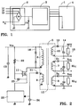
- Figure 1 shows the internal organization of an example of a three-phase meter that can withstand a loss of neutral.
- This counter referenced by 1 is formed by a supply circuit comprising a rectifier part 2 and a DC / DC converter part 3 as well as a metrological circuit 4.
- the first part, the rectifier circuit 2 allows the connection of the counter 1 at the three phases L 1 , L 2 , L 3 and at neutral N of the three-phase network and supplies a direct voltage output to a main capacitor C o .
- the object of the invention is to obtain an image of this DC voltage across the terminals of C o which is found at the input of the DC / DC converter circuit 3 in order to detect any current drops in the network.
- the rectifier circuit 2 and the converter circuit 3 supply the metrological circuit 4.
- the DC / DC converter circuit used consists of a switching circuit with a PWM regulator 20 and a transformer 5.
- PWM regulator 20 we also recognize as input the main capacitor C o which we want to get the image of the voltage.
- the supply circuits and the metrological circuit do not have the same potential reference.
- the capacitor C o , the PWM regulator 20 and the primary circuit 6 of the transformer 5 are referenced with respect to the mass of the circuit while the whole of the secondary circuit composed of elements 7, 8, 10, which supplies the metrological circuit, as well as the metrological circuit itself is referenced with respect to the neutral.
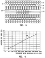
- the transformer 5 used, presented in FIG. 3, is initially formed from four different successive windings: a primary winding 6 which is wound around the toroid 12, a return winding 9 around the primary winding 6, a first secondary winding 7 around the return winding 9 and finally a second secondary winding 8 around the first secondary winding 7.
- a primary winding 6 which is wound around the toroid 12
- a return winding 9 around the primary winding 6
- a first secondary winding 7 around the return winding 9
- a second secondary winding 8 around the first secondary winding 7.
- each secondary circuit includes a diode, a capacitor and a resistance placed in parallel with the winding.
- winding direction of the windings indicated on the diagrams conventionally by the point located next to each winding, and the orientation of the diodes are reversed between the 2 circuits to obtain respectively a positive voltage at the output of the first circuit secondary and a negative voltage at the output of the second circuit secondary.
- the return winding 9 connected to a diode 21 and to a capacitor 24 monitors the voltage across the secondary circuits and has the role of modifying the primary voltage to obtain the DC voltages at the output of the secondary circuits. There is a strong coupling between the return winding and the secondary.
- This return circuit under the influence of the secondary circuits, controls the PWM regulator 20 and a transistor 11. The latter two form a switching circuit which controls the connection time of the main capacitor C to the primary winding 6.
- a circuit 16, composed of a Zener diode and a conventional diode, is moreover introduced in parallel to the primary winding to limit the overvoltage due to the electromotive force induced in the inductor of the primary during the opening of the switching circuit.
- Zener diode is placed in parallel with the transistor 11 to protect it from too high a voltage applied to its terminals.
- a resistor 22 allows the polarization of the Zener diode 23 in order to control the transistor and protect its input from overvoltages.
- a primary winding 6 of 132 turns Take for example a primary winding 6 of 132 turns, a first secondary winding 7 of 23 turns, a second secondary winding 8 of 17 turns, a return winding 9 of 34 turns and a winding additional 10 of 4 rounds.
- the 132 turns of the primary winding are sufficient to create a shield around the additional winding for that this one does not undergo the influence of the return winding and the number of turns of the additional winding is small compared to that of the primary and inexpensive.
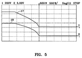
- FIG. 5 provides the indications of the values of the voltages at the terminals of the capacitor and output. For a voltage of 200 V at the input of the circuit DC / DC converter there is a voltage of 5 V at the output. he there is a 40: 1 ratio between the two voltages. The ratio between the number additional windings and the number of windings primary is preferably 1:33.
- the additional winding has a very strong coupling with the primary only. Thanks to a diode 13 connected to the additional winding and to a very low time constant integration circuit, the voltage obtained at the output is a faithful image of the voltage at the primary and therefore of that across the capacitor C o .
- the integration circuit defined by the capacitor 14, the resistor 15, and the diode 13, is dimensioned to allow filtering of the voltage and not to take into account the cutting of the voltage of the primary winding generated by the switching circuit. .
- Figure 4 shows the linearity relationship obtained between the output voltage and that across the capacitor C .
- Figure 5 shows the display of a connected oscilloscope to compare the time evolution of the voltage across the capacitor C , curve 17, and that of the output voltage, curve 18.
- the output voltage reproduces the voltage across the terminals of capacitor C, except for a shift .
- a change in the voltage across the capacitor immediately causes a change in the output voltage.
- a voltage drop in the network supply will therefore be instantly reproduced and identified at the output.
Landscapes
- Engineering & Computer Science (AREA)
- Power Engineering (AREA)
- Physics & Mathematics (AREA)
- General Physics & Mathematics (AREA)
- Dc-Dc Converters (AREA)
- Measurement Of Current Or Voltage (AREA)
Applications Claiming Priority (4)
| Application Number | Priority Date | Filing Date | Title |
|---|---|---|---|
| FR9709201A FR2766304B1 (fr) | 1997-07-17 | 1997-07-17 | Circuit d'alimentation pour un compteur d'electricite |
| FR9709201 | 1997-07-17 | ||
| US09/103,783 US5973941A (en) | 1997-07-17 | 1998-06-24 | Electricity meter with a switching mode transformer power supply circuit |
| CN98116035A CN1131434C (zh) | 1997-07-17 | 1998-07-15 | 用于电表的电源电路 |
Publications (2)
| Publication Number | Publication Date |
|---|---|
| EP0892273A1 true EP0892273A1 (de) | 1999-01-20 |
| EP0892273B1 EP0892273B1 (de) | 2004-04-07 |
Family
ID=27179203
Family Applications (1)
| Application Number | Title | Priority Date | Filing Date |
|---|---|---|---|
| EP98202030A Expired - Lifetime EP0892273B1 (de) | 1997-07-17 | 1998-06-17 | Versorgungsschaltung für einen Elektizitätszähler |
Country Status (11)
| Country | Link |
|---|---|
| US (1) | US5973941A (de) |
| EP (1) | EP0892273B1 (de) |
| CN (1) | CN1131434C (de) |
| BR (1) | BR9802411B1 (de) |
| CA (1) | CA2242799A1 (de) |
| DE (1) | DE69822930T2 (de) |
| ES (1) | ES2221973T3 (de) |
| FR (1) | FR2766304B1 (de) |
| HU (1) | HU223914B1 (de) |
| PT (1) | PT892273E (de) |
| ZA (1) | ZA985816B (de) |
Cited By (1)
| Publication number | Priority date | Publication date | Assignee | Title |
|---|---|---|---|---|
| WO2014049279A1 (fr) * | 2012-09-28 | 2014-04-03 | Valeo Systemes De Controle Moteur | Procédé et dispositif de mesure d'une tension isolée |
Families Citing this family (21)
| Publication number | Priority date | Publication date | Assignee | Title |
|---|---|---|---|---|
| CN2397497Y (zh) * | 1999-11-23 | 2000-09-20 | 北京科博智能仪表有限责任公司 | 具有新型电源模块的电度表 |
| EP1416575A1 (de) * | 2002-10-30 | 2004-05-06 | STMicroelectronics S.A. | Symmetrierübertrager |
| GB0402319D0 (en) * | 2004-02-03 | 2004-03-10 | M & Fc Holdings Llc | Wide range power supply for polyphase electricity meter |
| JP4671019B2 (ja) * | 2005-01-14 | 2011-04-13 | サンケン電気株式会社 | 多出力型dc−dcコンバータ |
| DE102005015942A1 (de) * | 2005-04-07 | 2006-10-12 | Abb Patent Gmbh | Einrichtung zur Energieversorgung von Messsensoren und Übertragung eins synchronen Taktsignals an diese |
| US7755915B2 (en) * | 2006-12-01 | 2010-07-13 | Innocom Technology (Shenzhen) Co., Ltd. | Power supply circuit with at least one feedback circuit feeding operating state of transformer back to pulse width modulation circuit thereof |
| TW200950299A (en) * | 2008-05-30 | 2009-12-01 | Gio Optoelectronics Corp | Single-stage AC to DC conversion device |
| US7772812B2 (en) * | 2008-07-17 | 2010-08-10 | Elster Electricity, Llc | System and method for providing a DC voltage source within a power meter |
| EP2154539B1 (de) | 2008-08-14 | 2011-04-13 | Kamstrup A/S | Verbrauchsmesser mit Magnetdetektor |
| EP2209013B1 (de) * | 2009-01-17 | 2016-11-09 | EMH metering GmbH & Co. KG | Elektronischer Mehrphasenzähler |
| US20130151319A1 (en) * | 2011-12-07 | 2013-06-13 | Yang Pan | Predictable Method for Reducing Power Consumption during Peak Demand |
| CN102830368A (zh) * | 2012-07-04 | 2012-12-19 | 尚艳燕 | 一种用于检测pc电源的电子负载机 |
| CN103219889B (zh) * | 2013-03-22 | 2018-04-06 | 华立科技股份有限公司 | 电力采集设备用的多路输出式隔离电源,分立元件式隔离型电源电路以及电力采集设备 |
| US10277136B2 (en) * | 2016-12-01 | 2019-04-30 | Power Integrations, Inc. | Controller for multi-output single magnetic component converter with independent regulation of constant current and constant voltage outputs |
| RU180905U1 (ru) * | 2017-12-08 | 2018-06-29 | Акционерное общество "Радио и Микроэлектроника" | Токовая цепь счетчика электрической энергии |
| CN107947606A (zh) * | 2017-12-25 | 2018-04-20 | 福建顺昌虹润精密仪器有限公司 | 一种仪表电源 |
| US10218282B1 (en) * | 2018-05-31 | 2019-02-26 | Power Integrations, Inc. | Method and apparatus for sequencing outputs in a multi-output power converter system |
| JP2020018037A (ja) | 2018-07-23 | 2020-01-30 | 株式会社デンソー | パワー素子駆動装置 |
| CN110932559A (zh) * | 2019-12-03 | 2020-03-27 | 成都长城开发科技有限公司 | 电表的电源模块 |
| CN115642026A (zh) * | 2022-10-18 | 2023-01-24 | 成都长城开发科技股份有限公司 | 一种用于电能计量的变压器骨架、层叠设计和反激电源 |
| WO2026009361A1 (ja) * | 2024-07-04 | 2026-01-08 | 株式会社オートネットワーク技術研究所 | 信号伝送装置 |
Citations (3)
| Publication number | Priority date | Publication date | Assignee | Title |
|---|---|---|---|---|
| EP0129454A1 (de) * | 1983-06-17 | 1984-12-27 | Telemecanique | Messverfahren um die Verfügbarkeit einer getakteten elektrischen Stromversorgung festzustellen und Vorrichtung zu seiner Durchführung |
| WO1992005614A1 (en) * | 1990-09-26 | 1992-04-02 | Allied-Signal Inc. | Uninterruptible power supply |
| GB2286250A (en) * | 1991-09-19 | 1995-08-09 | Ampy Automation Digilog | Power meter |
Family Cites Families (3)
| Publication number | Priority date | Publication date | Assignee | Title |
|---|---|---|---|---|
| GB9116616D0 (en) * | 1991-08-01 | 1991-09-18 | Thomson Consumer Electronics | Switched mode power supply with startup precharge |
| US5414610A (en) * | 1993-06-21 | 1995-05-09 | Ast Research, Inc. | Universal power converter with single, shared power transformation circuit |
| US5841641A (en) * | 1996-05-01 | 1998-11-24 | Compaq Computer Corporation | Protected zero-crossing detection using switching transistor's on-resistance |
-
1997
- 1997-07-17 FR FR9709201A patent/FR2766304B1/fr not_active Expired - Fee Related
-
1998
- 1998-06-17 DE DE69822930T patent/DE69822930T2/de not_active Expired - Lifetime
- 1998-06-17 ES ES98202030T patent/ES2221973T3/es not_active Expired - Lifetime
- 1998-06-17 PT PT98202030T patent/PT892273E/pt unknown
- 1998-06-17 EP EP98202030A patent/EP0892273B1/de not_active Expired - Lifetime
- 1998-06-24 US US09/103,783 patent/US5973941A/en not_active Expired - Lifetime
- 1998-07-02 ZA ZA985816A patent/ZA985816B/xx unknown
- 1998-07-02 CA CA002242799A patent/CA2242799A1/fr not_active Abandoned
- 1998-07-09 BR BRPI9802411-6A patent/BR9802411B1/pt not_active IP Right Cessation
- 1998-07-15 CN CN98116035A patent/CN1131434C/zh not_active Expired - Fee Related
- 1998-07-16 HU HU9801611A patent/HU223914B1/hu not_active IP Right Cessation
Patent Citations (3)
| Publication number | Priority date | Publication date | Assignee | Title |
|---|---|---|---|---|
| EP0129454A1 (de) * | 1983-06-17 | 1984-12-27 | Telemecanique | Messverfahren um die Verfügbarkeit einer getakteten elektrischen Stromversorgung festzustellen und Vorrichtung zu seiner Durchführung |
| WO1992005614A1 (en) * | 1990-09-26 | 1992-04-02 | Allied-Signal Inc. | Uninterruptible power supply |
| GB2286250A (en) * | 1991-09-19 | 1995-08-09 | Ampy Automation Digilog | Power meter |
Cited By (2)
| Publication number | Priority date | Publication date | Assignee | Title |
|---|---|---|---|---|
| WO2014049279A1 (fr) * | 2012-09-28 | 2014-04-03 | Valeo Systemes De Controle Moteur | Procédé et dispositif de mesure d'une tension isolée |
| FR2996309A1 (fr) * | 2012-09-28 | 2014-04-04 | Valeo Sys Controle Moteur Sas | Procede et dispositif de mesure d'une tension isolee |
Also Published As
| Publication number | Publication date |
|---|---|
| US5973941A (en) | 1999-10-26 |
| FR2766304A1 (fr) | 1999-01-22 |
| BR9802411B1 (pt) | 2010-10-05 |
| HUP9801611A2 (hu) | 1999-04-28 |
| CN1206111A (zh) | 1999-01-27 |
| HU9801611D0 (en) | 1998-09-28 |
| FR2766304B1 (fr) | 1999-10-01 |
| ZA985816B (en) | 1999-01-26 |
| ES2221973T3 (es) | 2005-01-16 |
| HUP9801611A3 (en) | 2000-06-28 |
| EP0892273B1 (de) | 2004-04-07 |
| CN1131434C (zh) | 2003-12-17 |
| PT892273E (pt) | 2004-08-31 |
| HU223914B1 (hu) | 2005-03-29 |
| BR9802411A (pt) | 1999-06-29 |
| DE69822930D1 (de) | 2004-05-13 |
| CA2242799A1 (fr) | 1999-01-17 |
| DE69822930T2 (de) | 2005-04-28 |
Similar Documents
| Publication | Publication Date | Title |
|---|---|---|
| EP0892273B1 (de) | Versorgungsschaltung für einen Elektizitätszähler | |
| EP0116509B1 (de) | Wechselstrom-Messwertgeber | |
| EP0493272A1 (de) | Schutzschalter mit einer Schnittstellenkarte für einen Auslöser | |
| EP0612982B2 (de) | Messschaltung für Widerstandssensor, insbesondere Krafstoffmesser | |
| FR2476837A1 (fr) | Dispositif pour alimenter en tension des installations destinees a detecter des fluctuations de pression dans la chambre de combustion d'un moteur a combustion interne | |
| FR2471708A1 (fr) | Circuit d'alimentation en courant comportant une fonction de detection de court-circuit a la terre pour systeme de telecommunication | |
| FR2649797A1 (fr) | Circuit de detection du signal phase alternateur polyphase de controle d'un regulateur de charge de batterie de vehicule automobile et son utilisation | |
| EP0592337B2 (de) | Elektronischer Auslöser mit Erdschutz | |
| EP0787994B1 (de) | Stromzähler | |
| FR2749083A1 (fr) | Agencement pour le controle de la charge d'un ensemble modulaire de cellules electrochimiques raccordees en serie et module correspondant de mesure pour cellule | |
| EP0490711B1 (de) | Elektrische Messanordnung mit zwei Schaltungskonfigurationen | |
| FR2684188A1 (fr) | Dispositif de mesure du taux de charge reel d'un generateur electrique. | |
| EP0628828B1 (de) | Mess- und Zählvorrichtung für elektrische Energie | |
| FR2700076A1 (fr) | Déclencheur électronique comportant un dispositif de test. | |
| FR2967260A1 (fr) | Mesure de courant pour radiateur electrique | |
| EP0112200B1 (de) | Mit einem Vielfachmessgerät verbindbares Zusatzgerät zum Messen von Erdungswiderständen | |
| FR2572860A1 (fr) | Regulateur electronique d'alternateur destine a la charge d'une batterie, notamment pour vehicule automobile | |
| EP3451181B1 (de) | Schutzschaltkreis gegen hohe spannungen für einen usb-empfänger vom typ c | |
| EP0030497B1 (de) | Schaltung zur Bestimmung des durch einen elektrischen Asynchronmotor gelieferten Kräftepaars | |
| EP0038240A1 (de) | Gleichstromversorgung und ihre Verwendung zum Speisen einer kathodischen Röhre | |
| FR2536223A1 (fr) | Dispositif pour alimenter en forte tension continue un appareil electrique consommateur | |
| EP0457649A1 (de) | Momentan-Leistungsmesschaltung | |
| FR2691597A1 (fr) | Récepteur de données numériques émises sous forme de signaux différentiels et ses utilisations. | |
| EP0609113B1 (de) | Vorrichtung zur Messung einer elektrischen Gleichstromgrösse, beispielsweise einer Spannung | |
| FR2697091A1 (fr) | Dispositif de mesure de courant par shunt. |
Legal Events
| Date | Code | Title | Description |
|---|---|---|---|
| PUAI | Public reference made under article 153(3) epc to a published international application that has entered the european phase |
Free format text: ORIGINAL CODE: 0009012 |
|
| AK | Designated contracting states |
Kind code of ref document: A1 Designated state(s): BE CH DE ES FR GR IT LI NL PT SE |
|
| AX | Request for extension of the european patent |
Free format text: AL;LT;LV;MK;RO;SI |
|
| 17P | Request for examination filed |
Effective date: 19990330 |
|
| AKX | Designation fees paid |
Free format text: BE CH DE ES FR GR IT LI NL PT SE |
|
| GRAP | Despatch of communication of intention to grant a patent |
Free format text: ORIGINAL CODE: EPIDOSNIGR1 |
|
| GRAS | Grant fee paid |
Free format text: ORIGINAL CODE: EPIDOSNIGR3 |
|
| GRAA | (expected) grant |
Free format text: ORIGINAL CODE: 0009210 |
|
| AK | Designated contracting states |
Kind code of ref document: B1 Designated state(s): BE CH DE ES FR GR IT LI NL PT SE |
|
| REG | Reference to a national code |
Ref country code: CH Ref legal event code: EP |
|
| REF | Corresponds to: |
Ref document number: 69822930 Country of ref document: DE Date of ref document: 20040513 Kind code of ref document: P |
|
| REG | Reference to a national code |
Ref country code: SE Ref legal event code: TRGR |
|
| REG | Reference to a national code |
Ref country code: GR Ref legal event code: EP Ref document number: 20040402237 Country of ref document: GR |
|
| REG | Reference to a national code |
Ref country code: PT Ref legal event code: SC4A Free format text: AVAILABILITY OF NATIONAL TRANSLATION Effective date: 20040706 |
|
| REG | Reference to a national code |
Ref country code: ES Ref legal event code: FG2A Ref document number: 2221973 Country of ref document: ES Kind code of ref document: T3 |
|
| PLBE | No opposition filed within time limit |
Free format text: ORIGINAL CODE: 0009261 |
|
| STAA | Information on the status of an ep patent application or granted ep patent |
Free format text: STATUS: NO OPPOSITION FILED WITHIN TIME LIMIT |
|
| 26N | No opposition filed |
Effective date: 20050110 |
|
| REG | Reference to a national code |
Ref country code: FR Ref legal event code: GC |
|
| REG | Reference to a national code |
Ref country code: CH Ref legal event code: PUE Owner name: ACTARIS SAS Free format text: SCHLUMBERGER INDUSTRIES S.A.#50, AVENUE JEAN-JAURES, BP. 620-05#92542 MONTROUGE CEDEX (FR) -TRANSFER TO- ACTARIS SAS#62 BIS AVENUE ANDRE MORIZET#92100 BOULOGNE-BILLANCOURT (FR) Ref country code: CH Ref legal event code: NV Representative=s name: CRONIN INTELLECTUAL PROPERTY |
|
| NLS | Nl: assignments of ep-patents |
Owner name: ACTARIS SAS Effective date: 20051212 |
|
| NLT1 | Nl: modifications of names registered in virtue of documents presented to the patent office pursuant to art. 16 a, paragraph 1 |
Owner name: SCHLUMBERGER S.A. |
|
| REG | Reference to a national code |
Ref country code: PT Ref legal event code: PD4A Owner name: SCHLUMBERGER S.A., FR Effective date: 20060315 Ref country code: PT Ref legal event code: PC4A Owner name: ACTARIS S.A.S., FR Effective date: 20060315 |
|
| REG | Reference to a national code |
Ref country code: FR Ref legal event code: TP Ref country code: CH Ref legal event code: PCAR Free format text: CRONIN INTELLECTUAL PROPERTY;CHEMIN DE PRECOSSY 31;1260 NYON (CH) Ref country code: FR Ref legal event code: CD |
|
| BECH | Be: change of holder |
Owner name: *ACTARIS S.A.S. Effective date: 20051221 |
|
| PGFP | Annual fee paid to national office [announced via postgrant information from national office to epo] |
Ref country code: ES Payment date: 20120627 Year of fee payment: 15 |
|
| PGFP | Annual fee paid to national office [announced via postgrant information from national office to epo] |
Ref country code: DE Payment date: 20130627 Year of fee payment: 16 Ref country code: CH Payment date: 20130627 Year of fee payment: 16 Ref country code: SE Payment date: 20130627 Year of fee payment: 16 |
|
| PGFP | Annual fee paid to national office [announced via postgrant information from national office to epo] |
Ref country code: IT Payment date: 20130625 Year of fee payment: 16 Ref country code: FR Payment date: 20130702 Year of fee payment: 16 Ref country code: PT Payment date: 20130607 Year of fee payment: 16 Ref country code: GR Payment date: 20130627 Year of fee payment: 16 |
|
| PGFP | Annual fee paid to national office [announced via postgrant information from national office to epo] |
Ref country code: BE Payment date: 20130627 Year of fee payment: 16 |
|
| PGFP | Annual fee paid to national office [announced via postgrant information from national office to epo] |
Ref country code: NL Payment date: 20130626 Year of fee payment: 16 |
|
| REG | Reference to a national code |
Ref country code: FR Ref legal event code: CD Owner name: ITRON FRANCE, FR Effective date: 20140423 Ref country code: FR Ref legal event code: CA Effective date: 20140423 |
|
| REG | Reference to a national code |
Ref country code: NL Ref legal event code: TD Effective date: 20140520 |
|
| REG | Reference to a national code |
Ref country code: DE Ref legal event code: R082 Ref document number: 69822930 Country of ref document: DE Representative=s name: KOENIG SZYNKA TILMANN VON RENESSE PATENTANWAEL, DE Effective date: 20140515 Ref country code: DE Ref legal event code: R081 Ref document number: 69822930 Country of ref document: DE Owner name: ITRON FRANCE, FR Free format text: FORMER OWNER: ACTARIS S.A.S., BOULOGNE, FR Effective date: 20140515 |
|
| REG | Reference to a national code |
Ref country code: CH Ref legal event code: PFA Owner name: ITRON FRANCE, FR Free format text: FORMER OWNER: ACTARIS SAS, FR |
|
| REG | Reference to a national code |
Ref country code: ES Ref legal event code: PC2A Owner name: ITRON FRANCE Effective date: 20140626 |
|
| REG | Reference to a national code |
Ref country code: PT Ref legal event code: MM4A Free format text: LAPSE DUE TO NON-PAYMENT OF FEES Effective date: 20141217 |
|
| REG | Reference to a national code |
Ref country code: DE Ref legal event code: R119 Ref document number: 69822930 Country of ref document: DE |
|
| REG | Reference to a national code |
Ref country code: NL Ref legal event code: V1 Effective date: 20150101 |
|
| PG25 | Lapsed in a contracting state [announced via postgrant information from national office to epo] |
Ref country code: PT Free format text: LAPSE BECAUSE OF NON-PAYMENT OF DUE FEES Effective date: 20141217 Ref country code: SE Free format text: LAPSE BECAUSE OF NON-PAYMENT OF DUE FEES Effective date: 20140618 |
|
| REG | Reference to a national code |
Ref country code: CH Ref legal event code: PL |
|
| REG | Reference to a national code |
Ref country code: SE Ref legal event code: EUG |
|
| REG | Reference to a national code |
Ref country code: GR Ref legal event code: ML Ref document number: 20040402237 Country of ref document: GR Effective date: 20150105 |
|
| REG | Reference to a national code |
Ref country code: DE Ref legal event code: R119 Ref document number: 69822930 Country of ref document: DE Effective date: 20150101 |
|
| REG | Reference to a national code |
Ref country code: FR Ref legal event code: ST Effective date: 20150227 |
|
| PG25 | Lapsed in a contracting state [announced via postgrant information from national office to epo] |
Ref country code: NL Free format text: LAPSE BECAUSE OF NON-PAYMENT OF DUE FEES Effective date: 20150101 |
|
| PG25 | Lapsed in a contracting state [announced via postgrant information from national office to epo] |
Ref country code: IT Free format text: LAPSE BECAUSE OF NON-PAYMENT OF DUE FEES Effective date: 20140617 Ref country code: LI Free format text: LAPSE BECAUSE OF NON-PAYMENT OF DUE FEES Effective date: 20140630 Ref country code: CH Free format text: LAPSE BECAUSE OF NON-PAYMENT OF DUE FEES Effective date: 20140630 Ref country code: DE Free format text: LAPSE BECAUSE OF NON-PAYMENT OF DUE FEES Effective date: 20150101 |
|
| PG25 | Lapsed in a contracting state [announced via postgrant information from national office to epo] |
Ref country code: GR Free format text: LAPSE BECAUSE OF NON-PAYMENT OF DUE FEES Effective date: 20150105 Ref country code: FR Free format text: LAPSE BECAUSE OF NON-PAYMENT OF DUE FEES Effective date: 20140630 |
|
| REG | Reference to a national code |
Ref country code: ES Ref legal event code: FD2A Effective date: 20150727 |
|
| PG25 | Lapsed in a contracting state [announced via postgrant information from national office to epo] |
Ref country code: ES Free format text: LAPSE BECAUSE OF NON-PAYMENT OF DUE FEES Effective date: 20140618 |
|
| PG25 | Lapsed in a contracting state [announced via postgrant information from national office to epo] |
Ref country code: BE Free format text: LAPSE BECAUSE OF NON-PAYMENT OF DUE FEES Effective date: 20140630 |