EP0892225A2 - Air conditioning apparatus and its components - Google Patents
Air conditioning apparatus and its components Download PDFInfo
- Publication number
- EP0892225A2 EP0892225A2 EP98112577A EP98112577A EP0892225A2 EP 0892225 A2 EP0892225 A2 EP 0892225A2 EP 98112577 A EP98112577 A EP 98112577A EP 98112577 A EP98112577 A EP 98112577A EP 0892225 A2 EP0892225 A2 EP 0892225A2
- Authority
- EP
- European Patent Office
- Prior art keywords
- condenser
- unit according
- sorption
- sorption unit
- evaporator
- Prior art date
- Legal status (The legal status is an assumption and is not a legal conclusion. Google has not performed a legal analysis and makes no representation as to the accuracy of the status listed.)
- Granted
Links
Images


Classifications
-
- F—MECHANICAL ENGINEERING; LIGHTING; HEATING; WEAPONS; BLASTING
- F25—REFRIGERATION OR COOLING; COMBINED HEATING AND REFRIGERATION SYSTEMS; HEAT PUMP SYSTEMS; MANUFACTURE OR STORAGE OF ICE; LIQUEFACTION SOLIDIFICATION OF GASES
- F25B—REFRIGERATION MACHINES, PLANTS OR SYSTEMS; COMBINED HEATING AND REFRIGERATION SYSTEMS; HEAT PUMP SYSTEMS
- F25B39/00—Evaporators; Condensers
-
- F—MECHANICAL ENGINEERING; LIGHTING; HEATING; WEAPONS; BLASTING
- F24—HEATING; RANGES; VENTILATING
- F24F—AIR-CONDITIONING; AIR-HUMIDIFICATION; VENTILATION; USE OF AIR CURRENTS FOR SCREENING
- F24F5/00—Air-conditioning systems or apparatus not covered by F24F1/00 or F24F3/00, e.g. using solar heat or combined with household units such as an oven or water heater
- F24F5/0007—Air-conditioning systems or apparatus not covered by F24F1/00 or F24F3/00, e.g. using solar heat or combined with household units such as an oven or water heater cooling apparatus specially adapted for use in air-conditioning
- F24F5/0014—Air-conditioning systems or apparatus not covered by F24F1/00 or F24F3/00, e.g. using solar heat or combined with household units such as an oven or water heater cooling apparatus specially adapted for use in air-conditioning using absorption or desorption
-
- F—MECHANICAL ENGINEERING; LIGHTING; HEATING; WEAPONS; BLASTING
- F25—REFRIGERATION OR COOLING; COMBINED HEATING AND REFRIGERATION SYSTEMS; HEAT PUMP SYSTEMS; MANUFACTURE OR STORAGE OF ICE; LIQUEFACTION SOLIDIFICATION OF GASES
- F25B—REFRIGERATION MACHINES, PLANTS OR SYSTEMS; COMBINED HEATING AND REFRIGERATION SYSTEMS; HEAT PUMP SYSTEMS
- F25B17/00—Sorption machines, plants or systems, operating intermittently, e.g. absorption or adsorption type
- F25B17/08—Sorption machines, plants or systems, operating intermittently, e.g. absorption or adsorption type the absorbent or adsorbent being a solid, e.g. salt
- F25B17/086—Sorption machines, plants or systems, operating intermittently, e.g. absorption or adsorption type the absorbent or adsorbent being a solid, e.g. salt with two or more boiler-sorber/evaporator units
-
- F—MECHANICAL ENGINEERING; LIGHTING; HEATING; WEAPONS; BLASTING
- F25—REFRIGERATION OR COOLING; COMBINED HEATING AND REFRIGERATION SYSTEMS; HEAT PUMP SYSTEMS; MANUFACTURE OR STORAGE OF ICE; LIQUEFACTION SOLIDIFICATION OF GASES
- F25B—REFRIGERATION MACHINES, PLANTS OR SYSTEMS; COMBINED HEATING AND REFRIGERATION SYSTEMS; HEAT PUMP SYSTEMS
- F25B35/00—Boiler-absorbers, i.e. boilers usable for absorption or adsorption
- F25B35/04—Boiler-absorbers, i.e. boilers usable for absorption or adsorption using a solid as sorbent
-
- Y—GENERAL TAGGING OF NEW TECHNOLOGICAL DEVELOPMENTS; GENERAL TAGGING OF CROSS-SECTIONAL TECHNOLOGIES SPANNING OVER SEVERAL SECTIONS OF THE IPC; TECHNICAL SUBJECTS COVERED BY FORMER USPC CROSS-REFERENCE ART COLLECTIONS [XRACs] AND DIGESTS
- Y02—TECHNOLOGIES OR APPLICATIONS FOR MITIGATION OR ADAPTATION AGAINST CLIMATE CHANGE
- Y02A—TECHNOLOGIES FOR ADAPTATION TO CLIMATE CHANGE
- Y02A30/00—Adapting or protecting infrastructure or their operation
- Y02A30/27—Relating to heating, ventilation or air conditioning [HVAC] technologies
-
- Y—GENERAL TAGGING OF NEW TECHNOLOGICAL DEVELOPMENTS; GENERAL TAGGING OF CROSS-SECTIONAL TECHNOLOGIES SPANNING OVER SEVERAL SECTIONS OF THE IPC; TECHNICAL SUBJECTS COVERED BY FORMER USPC CROSS-REFERENCE ART COLLECTIONS [XRACs] AND DIGESTS
- Y02—TECHNOLOGIES OR APPLICATIONS FOR MITIGATION OR ADAPTATION AGAINST CLIMATE CHANGE
- Y02B—CLIMATE CHANGE MITIGATION TECHNOLOGIES RELATED TO BUILDINGS, e.g. HOUSING, HOUSE APPLIANCES OR RELATED END-USER APPLICATIONS
- Y02B30/00—Energy efficient heating, ventilation or air conditioning [HVAC]
- Y02B30/62—Absorption based systems
Definitions
- the invention relates to a sorption unit according to the preamble of the claim 1, a buffer device according to the preamble of claim 19, a Condenser / evaporator unit according to the preamble of claim 15 or 27 and an air conditioning device which is formed from these elements, according to the preamble of claim 37.
- air conditioning rooms are, on the one hand, to constantly renew the air and on the other hand the creation of a defined temperature and climate condition, i.e. regulation of air temperature, air humidity and / or Filtering.
- air conditioning in the sense of the present invention is it primarily a temperature change, be it by a "Air conditioning" for cooling, a heat pump system or another application.
- processes are currently used for temperature air conditioning for use in which the sorption process takes place by cooling a sorption part is initiated and a working fluid evaporates in an evaporator becomes.
- the working fluid is sorbed exothermic in a sorbent and in a subsequent endothermic reaction (regeneration phase) again sorbed.
- the device used to carry out this method is in DE 42 33 062 described and consists essentially of several elongated Sorption containers (Kocheradsorberteil) that over part of their length with Zeolite serving as sorbent are filled and in this part an adsorber form.
- the other part of the length forms a condenser evaporator zone (Evaporator).
- the sorption containers rotate in two coaxial housings a circular path and are located with the Kocheradsorberteil in one Housing and with the evaporator part in the other housing.
- the Kocheradsorbermaschinesing housing has an inlet and an outlet for a gaseous heat transfer medium so that the heat transfer medium on its flow path through the housing both the Kocheradsorbermaschine Extracts heat as well as supplying heat.
- the Kocheradsorberteil has curved, elongated, flat in cross section Hollow body made of an approximately 0.1 mm thick stainless steel sheet are, the top of these sheets is smooth.
- the undersides are wavy curved sheets arranged.
- the sheets are on the apex lines of the Waves by roll welds or by laser treatment with each other connected.
- the approx. 600 mm long and approx. 80 mm wide sheets are made of zeolite coated, the zeolite layer being produced in a multi-layer application process is applied.
- the arches touch the smooth stainless steel sheet and thereby support it. This shape creates channels through which water vapor is passed.
- the problems further worsen the air conditioner in the evaporator area.
- the generic evaporator - as well as the temperature insulating Area between evaporator and sorption zone (buffer device called) - have the problem that not enough prevented is that even larger water droplets during the adsorption of water in the zeolite are entrained by the evaporator into the sorption unit, so that then Water droplets could enter the zeolite fraction directly. This worsens the efficiency of the air conditioner because the water droplets do not heat from the room surrounding the evaporator.
- the invention is therefore aimed at the generic air conditioner and its Develop components in such a way that it is simple and inexpensive Manufacturing results, the function of the device and its components should be guaranteed even after prolonged operation.
- the invention achieves this goal with regard to the components sorption unit, Buffer device and condenser / evaporator unit through the objects of claims 1, 19, 23, and 27 and with regard to the device the subject matter of claim 37.
- the invention creates a sorption unit for air conditioning and heating technology devices with sheets for heat emission, on which a working medium is directed, wherein the sheets are in contact with a sorbent which forms strand-like profile body, which are designed such that they have a flat Have contact with the sheets and that by means of the strand-like profile body Channels for the passage of the working medium are formed.
- a sorbent can e.g. Zeolite and water are used as the working medium which evaporates in an evaporator and is adsorbed in the zeolite.
- water / zeolite combination are other known combinations usable, e.g. Ammonia / carbon, water / salt.
- the channels for passage are formed of the working medium between adjacent profile bodies.
- the profile bodies preferably have at least largely the shape of a Double-T or an X with the top and bottom closed to one to form the largest possible contact area. These bodies then become used to fill the space between double sheets.
- the profile pieces can also preferably be arranged parallel to one another and can have a different length.
- the double T or X pieces are also designed so that a large area Contact area to the sheets results, which makes a good at these points Heat transfer takes place. Because zeolite has a relatively poor thermal conductivity, if the inside area is heated less, this effect is however insignificant due to the constriction.
- the channels are for the passage of the working medium formed in the profile bodies and run in the longitudinal direction the profile body.
- the profile body are also designed so that a there is a large contact area with the sheets.
- the profile body preferably a square cross-sectional shape, with the channels in the bodies preferred are arranged axially symmetrical with respect to the longitudinal direction of the profile body and a circular or square cross section or a square Have a cross-section with rounded corners.
- a profile body can also have two, three or several adjacent sections with a square cross-sectional shape have, with in each of these sections a channel along the Longitudinal axis of the body, preferably in the center of the cross section of the section, located.
- the profile bodies are preferably arranged parallel to one another and a different one Have length.
- the embodiment just described has the advantage that when inserting the profile body between the sheets of Sorption unit was not considered due to the symmetry of the profile body which sides of the body touch the sheets. This will make the Installation of the profile body made easier.
- the end faces of the profile pieces according to a further variant of the invention are not even (e.g. broken), they do not lie next to each other to form a seal, so that openings or connections are formed between the channels, which ensure problem-free pressure equalization between the channels.
- a plurality of double sheet metal elements to form a superimposed and / or side by side Sorber / condenser evaporator package which is the simplest Way through appropriate geometry and combination of device components can be adapted to various purposes.
- the Capacitor performance through appropriate additional elements or additional double sheet layers easy to raise.
- the units are built up in layers, so that for example up to 100 "climate elements", each with its own sorption and Cover the condenser / evaporator section to form the complete air conditioner.
- it is preferably between the part of the sorption unit in which the zeolite chains are arranged and the condenser / evaporator part according to the invention a buffer zone or a buffer device which prevents that heat given off in the zeolite part reaches the evaporator (if the evaporator serves to generate cold).
- this buffer zone is equipped with a water separation device provided, preferably a structure of a plurality of parallel to each other arranged sheets, each with embossments on both sides are that as a spacer to the adjacent sheet and / or as Collect recesses for liquid droplets.
- a water separation device provided, preferably a structure of a plurality of parallel to each other arranged sheets, each with embossments on both sides are that as a spacer to the adjacent sheet and / or as Collect recesses for liquid droplets.
- the water separation effect is measured in this way (by appropriate interpretation of the impressions) that the performance of the device is not is further reduced because the flow of water vapor to the sorption unit should not in itself be negatively influenced. Only interception Larger drops of water are desirable.
- the impressions are in this area of the buffer zone are also curved upwards, or point at the lateral edge areas down so that the swirling water droplets are intercepted and be led back down into the evaporator.
- the Regeneration phase of the sorption unit expelled water vapor to the Condensate the impressions and down into the condenser / evaporator unit can drain off.
- the invention achieves it Target by the subject matter of claim 23 or 27. It becomes a condenser / evaporator unit created for air conditioning and heating technology devices also characterized by a liquid separator, one A plurality of sheets arranged parallel to each other is provided, each Both sides are provided with embossments that act as spacers for each adjacent sheet and / or as catch recesses for liquid droplets to serve. These impressions hinder the flow through in a simple manner of water droplets through the condenser / evaporator unit below and stabilize the position of the sheets to each other.
- the impressions run curved downward so that they form collecting trays, and the distance between the impressions can be variable.
- the impressions can also be bent further closer to the sorption unit, so that they can hold more water than the lower spacers. This is i.a. therefore advantageous because in this way the most even possible distribution over the entire condenser / evaporator unit (to the sorption unit flowing water quantities increase towards the sorption unit).
- the steam flows through it on its way to the sorption unit kind of "labyrinth", in which when flowing around a corner or an arch water droplets are thrown off in the steam by centrifugal forces and on the water separator of the buffer section or on the spacer bars the condenser / evaporator unit get stuck, so that if possible Water is retained in the condenser / evaporator unit until it is complete evaporated.
- the impressions favor the condensation process and ensure an even distribution of water in the condenser / evaporator unit.
- the condenser / evaporator unit can also advantageously be a hollow body be formed in which an insert made of highly hygroscopic material, such as B. a felt or a glass fiber material, with areal extent can be inserted.
- B. highly hygroscopic material
- These support structures can e.g. B. from Screen plates are formed, which have embossments to increase stability can. However, it is advantageous if these embossments of the fiber material are facing away so that they do not lead to a compression of the material.
- the spacers can be formed by the support structure itself, wherein it is advantageous that this support structure is meandering, zigzag or is wavy.
- To stabilize the spacers can be in the sheet metal walls are provided with rib-shaped indentations or stampings, which arranged alternately and at a distance from each other on the spacers are.
- all sheet metal parts can improve the hygroscopic Properties be surface treated, this being mechanical and / or chemical nature can happen.
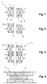
- Fig. 1 shows a section 1 of a sorption unit 2 of a device for air conditioning and Heat technology according to Fig. 9, with sheets for heat emission, on which water vapor is passed by.
- the sheets are double sheets with sheet metal walls 3 and 3 ', which are connected to one another at their ends (e.g. welded) are.
- strand-like zeolite profile body 4 arranged in the hollow chambers formed by the sheets 3 and 3 ' strand-like zeolite profile body 4 arranged. These have a double T shape on, with the top and bottom sides of the double-T in surface contact with the Sheets 3 and 3 'stand.
- the upper sides or Bottom sides of the X-body are designed to be as large as possible To form contact surface.
- the adjacent X-bodies or double T-bodies form in the area their constrictions 5 each from channels 6 through which the steam flow can.
- the adjacent X-bodies or double T-bodies form in the area their constrictions 5 each from channels 6 through which the steam flow can.
- A is preferably used in the sorption unit or in the entire air conditioning unit Maintain pressure below atmospheric pressure. With that presses the external pressure of the relatively thin sheets 3 and 3 'against each other, and the zeolite bodies are pressed against the sheets 3 and 3 'and in their position held.
- the device components sorption unit 2, buffer device 8 and condenser / evaporator unit 7 are designed as a laminated core, with each Sheets 9a, 9b, 9c, etc. are parallel to each other, which are stamped on both sides 10 and impressions 11, 14 are provided.
- These versions 10 and Imprints 11, 14 are arranged such that they have a combined effect as a "flow labyrinth", as a "water collecting basin” and as a mechanical "spacer” of the sheets 9a, 9b, etc. unfold.
- the impressions serve as collecting trays of condensing water vapor in the regeneration phase of the sorption device.
- impressions 11 are therefore also down in the buffer zone 8 curved to stop the water droplets and drain them down, while curved upward in the condenser / evaporator unit 7, to serve as drip trays so that the condensed water is even is distributed in the condenser / evaporator unit and not only in the accumulates lower area.
- the forms 10 can each over half of the sorption unit 2 or the condenser / evaporator unit 7 are preferably mutually arranged and complement each other Characteristics 10 of a second sorption unit or condenser / evaporator unit, on the first sorption unit or condenser / evaporator unit is hung up to form a package.
- These characteristics 10 serve in their mutual addition as a continuous spacer across the entire Width of the units and thus form an additional part of an air conditioner Flow channels for the passage of a room air flow, which in the Area of the evaporator 7 heat is withdrawn, or in the area of the sorption unit 2 for absorbing heat from the exothermic process.
- On the other hand serves the air flow in the regeneration phase of the air conditioner in the area the sorption unit 2 for delivering heat to the zeolite and for cooling in the condensation of the water in the condenser / evaporator unit 7.
- the impressions 11 touch extend into the evaporator 7 from both sides and serve on this way as a support of the two sheets against each other.
- impressions 11 are straight in the lower area and in the area of their edges curved in an arc, and their distance from the sorption unit increases 2 towards the water separation effect due to the increasing To increase steam flow to the sorption unit 2.
- the impressions 11 serving as spacers can be in the upper region of the evaporator 7 have a somewhat greater curvature, so that the collected Amount of water there is greater than in the lower region of the evaporator 7, where the water condensate normally collects. That way advantageously achieved that the most uniform possible distribution during the cooking process of the evaporating water over the entire evaporator cross section of the Condenser / evaporator unit 7 takes place.
- On their underside they can be fin-like Have guide fins that ensure that the water even at a Inclination of the air conditioner (if it is located in a caravan, for example, on the driving on a downhill road or decelerating or accelerating exposed) is derived downwards.
- the top of the sheets can be mechanically and / or chemically roughened.
- FIG. 9 illustrates how, from a sorption unit 2 according to the invention, one inventive condenser / evaporator unit 7 and an inventive Buffer section 8 a "layered" and compact, made up of individual Storage elements existing air conditioner can be formed.
- the individual storage elements are placed one on top of the other, with the surfaces held at a distance by the spacers 10 serving as characteristics become.
- the transverse channels formed by the spacers are used for the passage of air (see arrow 13 in Fig. 9).
- the channels have an i.w. constant Cross-section so that a uniform air flow is generated and the air in the evaporator area can be cooled evenly.
- the condenser area of the sorption unit 2 heat generated by the air flow well dissipated.
- the condenser / evaporator unit 7 and sorption unit 2 can, as in the 9, can be directly connected by the buffer section 8. It is but also conceivable that the condenser / evaporator unit 7 and sorption unit 2 are connected via a longer pipeline, this pipeline itself can be designed as a capacitor by on its outside Appropriate cooling fins are arranged so that in the expulsion phase, in which the water contained in the zeolite is expelled by the application of heat and the sorption unit 2 is regenerated, generated water vapor in the area the pipeline is condensed and as water in the evaporator 7 got back.
- a valve could also be arranged in this pipeline, with which the connection between the evaporator 7 and the sorption unit 2 is temporarily closed and only opened when cooling capacity is requested.
- FIGS. 10 to 14 Alternative embodiments for the condenser / evaporator unit according to the invention result from FIGS. 10 to 14.
- the hollow body of the condenser / evaporator unit consists of two z. B. by roll welding interconnected sheet metal half-shells 15, 16, between which an insert 17 is taken from a highly hygroscopic material. Because this deposit is made Glass fiber or felt material is used to avoid dissolving the Provided a support structure 18 due to mechanical stress, which is formed by a screen plate.
- the sheet metal shell has on the top 15 rib-like forms 19, which serve as spacers for another Condenser / evaporator unit serve.
- the condenser / evaporator unit shown in FIG. 11 is similar to the previous embodiment, but are on both sides of the Insert 17 sieve plates 18 are provided, the sieve plates each only over extend the undulating area of the respective sheet metal half-shell, since the opposite side of the insert covered by the sheet metal half shell itself becomes.
- the spacers 19 are shortened in their longitudinal extent, however alternately on the surface of the respective sheet metal half shell 15 ' or 16 'arranged. Form the undulating areas of the sheet metal half-shells longitudinally extending channels through which the water vapor flows.
- two inserts 17 are provided, which are kept at a distance by means of a spacer 20.
- the spacer 20 can also consist of a screen plate, which essentially is bent in a meandering shape.
- the sheet can also be bent in a zigzag shape 13, as shown in the embodiment of FIG. 13, wherein In the web area and in the respective contact surfaces, indentations or stampings 21, 22 are provided. These impressions or features serve to stabilize the relatively thin-walled sheet. It is advantageous if the values are not in the Area of the contact surfaces of the inserts are arranged, as can be avoided should be that the deposits on these steep. Rather extend the expressions then fit into the space between the deposits or - in the contact area to the direction facing away from the insert.
Landscapes
- Engineering & Computer Science (AREA)
- Mechanical Engineering (AREA)
- General Engineering & Computer Science (AREA)
- Physics & Mathematics (AREA)
- Thermal Sciences (AREA)
- Life Sciences & Earth Sciences (AREA)
- Sustainable Development (AREA)
- Chemical & Material Sciences (AREA)
- Combustion & Propulsion (AREA)
- Sorption Type Refrigeration Machines (AREA)
- Drying Of Gases (AREA)
Abstract
Description
Die Erfindung betrifft eine Sorptionseinheit nach dem Oberbegriff des Anspruches
1, eine Puffervorrichtung nach dem Oberbegriff des Anspruches 19, eine
Kondensator-/Verdampfereinheit nach dem Oberbegriff des Anspruches 15 bzw.
27 und ein Gerät der Klimatechnik, welches aus diesen Elementen gebildet wird,
nach dem Oberbegriff des Anspruchs 37.The invention relates to a sorption unit according to the preamble of the
Aufgabe der Klimatisierung von Räumen ist einerseits die ständige Lufterneuerung und andererseits die Schaffung eines definierten Temperatur- und Klimazustandes, d.h. eine Regulierung der Lufttemperatur, der Luftfeuchtigkeit und/oder Filterung. Bei einer Klimatisierung im Sinne der vorliegenden Erfindung handelt es sich in erster Linie um eine Temperaturveränderung, sei es durch eine "Klimaanlage" zur Kühlung, eine Wärmepumpenanlage oder eine andere Anwendung.The task of air conditioning rooms is, on the one hand, to constantly renew the air and on the other hand the creation of a defined temperature and climate condition, i.e. regulation of air temperature, air humidity and / or Filtering. With air conditioning in the sense of the present invention is it primarily a temperature change, be it by a "Air conditioning" for cooling, a heat pump system or another application.
Bei der Temperatur-Klimatisierung kommen derzeit beispielsweise Verfahren zum Einsatz, bei welchen durch Abkühlen eines Sorptionsteiles der Sorptionsvorgang eingeleitet wird und in einem Verdampfer ein Arbeitsmittel verdampft wird. Das Arbeitsmittel wird exotherm in einem Sorptionsmittel sorbiert und in einer anschließenden endothermen Reaktion (Regenerationsphase) wieder sorbiert.For example, processes are currently used for temperature air conditioning for use in which the sorption process takes place by cooling a sorption part is initiated and a working fluid evaporates in an evaporator becomes. The working fluid is sorbed exothermic in a sorbent and in a subsequent endothermic reaction (regeneration phase) again sorbed.
Die zur Durchführung dieses Verfahrens verwendete Vorrichtung ist in der DE 42 33 062 beschrieben und besteht im wesentlichen aus mehreren langgestreckten Sorptionsbehältern (Kocheradsorberteil), die über einen Teil ihrer Länge mit als Sorptionsstoff dienendem Zeolith gefüllt sind und in diesem Teil einen Adsorber bilden. Der andere Teil der Länge bildet eine Kondensatorverdampferzone (Verdampfer). Die Sorptionsbehälter rotieren in zwei koaxialen Gehäusen auf einer Kreisbahn und befinden sich dabei mit dem Kocheradsorberteil in dem einen Gehäuse und mit dem Verdampferteil in dem anderen Gehäuse. Das die Kocheradsorberteile umschließende Gehäuse besitzt einen Zutritt und einen Auslaß für ein gasförmiges Wärmeträgermedium, so daß das Wärmeträgermedium auf seinem Strömungsweg durch das Gehäuse den Kocheradsorberteilen sowohl Wärme entzieht als auch Wärme zuführt.The device used to carry out this method is in DE 42 33 062 described and consists essentially of several elongated Sorption containers (Kocheradsorberteil) that over part of their length with Zeolite serving as sorbent are filled and in this part an adsorber form. The other part of the length forms a condenser evaporator zone (Evaporator). The sorption containers rotate in two coaxial housings a circular path and are located with the Kocheradsorberteil in one Housing and with the evaporator part in the other housing. The Kocheradsorberteile enclosing housing has an inlet and an outlet for a gaseous heat transfer medium so that the heat transfer medium on its flow path through the housing both the Kocheradsorberteile Extracts heat as well as supplying heat.
Der Kocheradsorberteil weist im Querschnitt gekrümmte, langgestreckte, flache Hohlkörper auf, die aus einem ca. 0,1 mm starken Edelstahlblech hergestellt sind, wobei die Oberseite dieser Bleche glatt ist. An den Unterseiten sind wellenförmig gebogene Bleche angeordnet. Die Bleche sind an den Scheitellinien der Wellen durch Rollschweißnähte oder durch eine Laserbehandlung miteinander verbunden. Die ca. 600 mm langen und ca. 80 mm breiten Bleche sind mit Zeolith beschichtet, wobei die Zeolithschicht bei der Herstellung in einem Mehrschicht-Auftragungsverfahren aufgebracht wird. Die Bogen berühren das glatte Edelstahlblech und stützen es dadurch ab. Durch diese Form werden Kanäle gebildet, durch welche Wasserdampf geleitet wird.The Kocheradsorberteil has curved, elongated, flat in cross section Hollow body made of an approximately 0.1 mm thick stainless steel sheet are, the top of these sheets is smooth. The undersides are wavy curved sheets arranged. The sheets are on the apex lines of the Waves by roll welds or by laser treatment with each other connected. The approx. 600 mm long and approx. 80 mm wide sheets are made of zeolite coated, the zeolite layer being produced in a multi-layer application process is applied. The arches touch the smooth stainless steel sheet and thereby support it. This shape creates channels through which water vapor is passed.
Problematisch ist insbesondere die aufwendige Herstellung, welche sich daraus ergibt, daß zunächst das Blech entsprechend ausgeformt und mit Zeolith beschichtet werden muß, wobei dies in einer oder in mehreren Schichten erfolgen kann. Ein weiterer Nachteil ist darin zu sehen, daß die Zeolithschicht dünn aufgetragen werden muß, weil Zeolith kein guter Wärmeleiter ist und die Gaspermeabilität von Zeolith nicht sehr gut ist.The complex production, which results from this, is particularly problematic shows that the sheet is first shaped accordingly and coated with zeolite must be done, this being done in one or more layers can. Another disadvantage is that the zeolite layer is applied thinly must be because zeolite is not a good heat conductor and the gas permeability of zeolite is not very good.
Das größte Problem ergibt sich allerdings daraus, daß die Verbindung zwischen dem Blech und dem Zeolith oftmals nicht beständig ist, weil das Stahlblech während der Rotation heiße und kalte Temperaturzonen durchläuft und infolgedessen ständig wechselnde Wärmedehnungen erfährt (beispielsweise in dem Fall, in dem die Bleche die Flügel eines Rotors bilden). Aus diesem Grund kann es vorkommen, daß sich im Betrieb Zeolithschichten lösen - entweder bereichsweise oder völlig - so daß die Beschichtung zerstört wird, sich die Kanäle zusetzen oder der Wärmeübergang ungleichmäßig erfolgt. An den Stellen, an denen die Zeolithschicht zerstört ist, wird auch die Funktion der Bleche bzw. des die Bleche aufweisenden Rotors verschlechtert.The biggest problem arises from the fact that the connection between the sheet and the zeolite is often not stable because the steel sheet during the rotation goes through hot and cold temperature zones and as a result undergoes constantly changing thermal expansions (for example in the case in which the sheets form the wings of a rotor). Because of this, it can happen that zeolite layers come loose during operation - either in certain areas or completely - so that the coating is destroyed, the channels clog or the heat transfer takes place unevenly. Where the zeolite layer is destroyed, the function of the sheets or the sheets exhibiting rotor deteriorated.
Eine weitere Verschlechterung des Klimagerätes ergibt sich durch die Probleme im Verdampferbereich. Die gattungsgemäßen Verdampfer - sowie auch der temperaturisolierende Bereich zwischen Verdampfer und Sorptionszone (Puffervorrichtung genannt) - weisen das Problem auf, daß nicht genügend verhindert wird, daß auch größere Wassertröpfchen bei der Adsorption des Wassers im Zeolith vom Verdampfer in die Sorptionseinheit mitgerissen werden, so daß dann Wassertröpfchen direkt in den Zeolithanteil eintreten könnten. Dies verschlechtert den Wirkungsgrad der Klimaanlage, da die Wassertröpfchen keine Wärme aus dem den Verdampfer umgebenden Raum aufgenommen haben.The problems further worsen the air conditioner in the evaporator area. The generic evaporator - as well as the temperature insulating Area between evaporator and sorption zone (buffer device called) - have the problem that not enough prevented is that even larger water droplets during the adsorption of water in the zeolite are entrained by the evaporator into the sorption unit, so that then Water droplets could enter the zeolite fraction directly. This worsens the efficiency of the air conditioner because the water droplets do not heat from the room surrounding the evaporator.
Die Erfindung zielt daher darauf ab, das gattungsgemäße Klimagerät sowie dessen Komponenten derart weiterzuentwickeln, daß sich eine einfache und kostengünstige Herstellung ergibt, wobei die Funktion des Gerätes und seiner Komponenten auch nach längerem Betrieb noch gewährleistet sein soll.The invention is therefore aimed at the generic air conditioner and its Develop components in such a way that it is simple and inexpensive Manufacturing results, the function of the device and its components should be guaranteed even after prolonged operation.
Die Erfindung erreicht dieses Ziel im Hinblick auf die Komponenten Sorptionseinheit,
Puffervorrichtung und Kondensator/Verdampfereinheit durch die Gegen-ständes
der Ansprüche 1, 19, 23, und 27 und im Hinblick auf das Gerät durch
den Gegenständ des Anspruches 37.The invention achieves this goal with regard to the components sorption unit,
Buffer device and condenser / evaporator unit through the objects
of
Vorteilhafte Ausgestaltungen der Erfindung sind den Unteransprüchen zu entnehmen.Advantageous embodiments of the invention can be found in the subclaims.
Die Erfindung schafft eine Sorptionseinheit für Klima- und Wärmetechnikgeräte mit Blechen zur Wärmeabgabe, an denen ein Arbeitsmedium vorbeigeleitet wird, wobei die Bleche mit einem Sorptionsmittel in Kontakt stehen, welches strangartige Profilkörper bildet, die derart ausgestaltet sind, daß sie einen flächigen Kontakt zu den Blechen aufweisen und daß mittels der strangartigen Profilkörper Kanäle zur Durchleitung des Arbeitsmediums gebildet werden. Als Sorptionsmittel kann z.B. Zeolith und als Arbeitsmedium Wasser verwendet werden, welches in einem Verdampfer verdampft und in dem Zeolith adsorbiert wird. Anstelle der Stoffpaarung Wasser/Zeolith sind auch andere an sich bekannte Paarungen verwendbar, wie z.B. Ammoniak/Kohlenstoff, Wasser/Salz.The invention creates a sorption unit for air conditioning and heating technology devices with sheets for heat emission, on which a working medium is directed, wherein the sheets are in contact with a sorbent which forms strand-like profile body, which are designed such that they have a flat Have contact with the sheets and that by means of the strand-like profile body Channels for the passage of the working medium are formed. As a sorbent can e.g. Zeolite and water are used as the working medium which evaporates in an evaporator and is adsorbed in the zeolite. Instead of the water / zeolite combination are other known combinations usable, e.g. Ammonia / carbon, water / salt.
In einer Ausführungsform der Erfindung bilden sich die Kanäle zur Durchleitung des Arbeitsmediums zwischen nebeneinander angeordneten Profilkörpern. Bevorzugt weisen dabei die Profilkörper zumindest weitgehend die Form eines Doppel-T oder eines X mit geschlossener Ober- und Unterseite auf, um eine möglichst große Berührungfläche zu bilden. Diese Körper werden dann dazu verwendet, den Zwischenraum zwischen Doppelblechen auszufüllen. Die Profilstücke können ferner bevorzugt parallel zueinander angeordnet werden und können eine unterschiedliche Länge aufweisen.In one embodiment of the invention, the channels for passage are formed of the working medium between adjacent profile bodies. The profile bodies preferably have at least largely the shape of a Double-T or an X with the top and bottom closed to one to form the largest possible contact area. These bodies then become used to fill the space between double sheets. The profile pieces can also preferably be arranged parallel to one another and can have a different length.
Mit dieser Ausführungsform der Erfindung bilden sich zwischen den Doppelblechen Bereiche neben- und hintereinanderliegender Profilstücke (z.B. Zeolith), wobei sich im Einschnürungsbereich aneinanderliegender Doppel-T-Stücke oder der X-Stücke jeweils ohne weiteres Kanäle für das durchströmende Arbeitsmedium (Wasser-) Dampf ausbilden. With this embodiment of the invention, form between the double sheets Areas of adjacent and successive profile pieces (e.g. zeolite), where in the constriction of adjacent double T-pieces or of the X-pieces each without further channels for the flowing medium Form (water) steam.
Die Doppel-T oder X-Stücke sind ferner so ausgelegt, daß sich ein großflächiger Kontaktbereich zu den Blechen ergibt, wodurch an diesen Stellen ein guter Wärmeübergang erfolgt. Da Zeolith eine relativ schlechte Wärmeleitfähigkeit besitzt, wird der innen liegende Bereich zwar weniger erwärmt, dieser Effekt ist jedoch aufgrund der Einschnürung unbedeutend.The double T or X pieces are also designed so that a large area Contact area to the sheets results, which makes a good at these points Heat transfer takes place. Because zeolite has a relatively poor thermal conductivity, if the inside area is heated less, this effect is however insignificant due to the constriction.
In einer weiteren Ausführungsform sind die Kanäle zur Durchleitung des Arbeitsmediums in den Profilkörpern ausgebildet und verlaufen in Längsrichtung der Profilkörper. Dabei sind die Profilkörper ebenfalls so ausgelegt, daß sich ein großer Kontaktbereich zu den Blechen ergibt. Bevorzugt haben die Profilkörper eine quadratische Querschnittsform, wobei die Kanäle in den Körpern bevorzugt achssymmetrisch bezüglich der Längsrichtung der Profilkörper angeordnet sind und einen kreisförmigen oder quadratischen Querschnitt oder einen quadratischen Querschnitt mit abgerundeten Ecken aufweisen. Vorzugsweise befindet sich in jedem Profilkörper jeweils ein Kanal entlang der Längsachse im Zentrum des Querschnitts des Körpers. Jedoch kann ein Profilkörper auch zwei, drei oder mehrere nebeneinander liegende Abschnitte mit quadratischer Querschnittsform aufweisen, wobei sich in jedem dieser Abschnitte jeweils ein Kanal entlang der Längsachse des Körpers, vorzugsweise im Zentrum des Querschnitts des Abschnitts, befindet. Wie bei der vorher beschriebenen Ausführungsform können die Profilkörper bevorzugt parallel zueinander angeordnet werden und eine unterschiedliche Länge aufweisen. Die gerade beschriebene Ausführungsform hat dabei den Vorteil, daß beim Einsetzen der Profilkörper zwischen die Bleche der Sorptionseinheit aufgrund der Symmetrie der Profilkörper nicht darauf geachtet weden muß, welche Seiten des Körpers die Bleche berühren. Dadurch wird der Einbau der Profilkörper erleichtert.In a further embodiment, the channels are for the passage of the working medium formed in the profile bodies and run in the longitudinal direction the profile body. The profile body are also designed so that a there is a large contact area with the sheets. The profile body preferably a square cross-sectional shape, with the channels in the bodies preferred are arranged axially symmetrical with respect to the longitudinal direction of the profile body and a circular or square cross section or a square Have a cross-section with rounded corners. Preferably located there is a channel in each profile body along the longitudinal axis in the center of the cross section of the body. However, a profile body can also have two, three or several adjacent sections with a square cross-sectional shape have, with in each of these sections a channel along the Longitudinal axis of the body, preferably in the center of the cross section of the section, located. As with the previously described embodiment the profile bodies are preferably arranged parallel to one another and a different one Have length. The embodiment just described has the advantage that when inserting the profile body between the sheets of Sorption unit was not considered due to the symmetry of the profile body which sides of the body touch the sheets. This will make the Installation of the profile body made easier.
Da die Stirnseiten der Profilstücke nach einer weiteren Variante der Erfindung nicht eben (beispielsweise gebrochen) sind, liegen sie nicht dichtend nebeneinander, so daß Öffnungen bzw. Verbindungen zwischen den Kanälen gebildet werden, die für einen problemlosen Druckausgleich zwischen den Kanälen sorgen.Since the end faces of the profile pieces according to a further variant of the invention are not even (e.g. broken), they do not lie next to each other to form a seal, so that openings or connections are formed between the channels, which ensure problem-free pressure equalization between the channels.
Nach einer weiteren besonders bevorzugten Variante der Erfindung ergänzen sich eine Mehrzahl an Doppelblechelementen zu einem über- und/oder nebeneinanderliegenden Sorber-/Kondensator- Verdampferpaket, welches auf einfachste Weise durch entsprechende Geometriegebung und Kombination von Gerätekomponenten an verschiedenste Einsatzzwecke anpassen läßt. Beispielsweise ist die Kondensatorleistung durch entsprechende Zusatzelemente bzw. Zusatzdoppelblechschichten unkompliziert erhöhbar.Supplement according to another particularly preferred variant of the invention a plurality of double sheet metal elements to form a superimposed and / or side by side Sorber / condenser evaporator package, which is the simplest Way through appropriate geometry and combination of device components can be adapted to various purposes. For example, the Capacitor performance through appropriate additional elements or additional double sheet layers easy to raise.
Bei einem besonders bevorzugten Klimagerät werden die Kondensator/Verdampfereinheit und die Sorptionseinheit quasi übereinander in einer Art Kompaktgerät angeordnet. Die Einheiten sind dabei schichtartig aufgebaut, so daß beispielsweise bis zu 100 "Klimaelemente", die jeweils einen eigenen Sorptions- und Kondensator-/Verdampfer-abschnitt umfassen, das komplette Klimagerät bilden. In diesem Fall liegt bevorzugt zwischen dem Teil der Sorptionseinheit, in welchem die Zeolithketten angeordnet sind und dem Kondensator-/Verdampferteil erfindungsgemäß eine Pufferzone bzw. eine Puffervorrichtung, die verhindert, daß im Zeolithteil abgegebene Wärme zum Verdampfer gelangt (sofern der Verdampfer der Kälteerzeugung dient).In a particularly preferred air conditioning unit, the condenser / evaporator unit and the sorption unit one above the other in a kind of compact device arranged. The units are built up in layers, so that for example up to 100 "climate elements", each with its own sorption and Cover the condenser / evaporator section to form the complete air conditioner. In this case, it is preferably between the part of the sorption unit in which the zeolite chains are arranged and the condenser / evaporator part according to the invention a buffer zone or a buffer device which prevents that heat given off in the zeolite part reaches the evaporator (if the evaporator serves to generate cold).
Erfindungsgemäß wird diese Pufferzone mit einer Wasserabscheidevorrichtung versehen, die vorzugsweise einen Aufbau aus einer Mehrzahl an parallel zueinander angeordneten Blechen hat, die jeweils beidseitig mit Einprägungen versehen sind, die als Abstandshalter zum jeweils benachbarten Blech und/oder als Auffangausnehmungen für Flüssigkeitströpfchen dienen. Diese Wasserabscheidevorrichtung ist insbesondere deshalb vorteilhaft, weil infolge des sehr starken Kochvorganges in der Verdampfungsphase aufgrund der Vakuumwirkung des Verdampfers zu große Flüssigkeitströpfchen mit dem in die Sorptionseinheit einströmenden Dampf mitgerissen werden können, welche in den Zeolithabschnitt der Sorptionseinheit eintreten und damit die Leistung des Klimagerätes herabsetzen. Dies verhindert der Wasserabscheider auf einfache Weise dadurch, daß der Wasserabscheider die Wassertröpfchen quasi "abfangt" und in den Verdampfer zurückleitet. Dabei wird die Wasserabscheidewirkung derart bemessen (durch entsprechende Auslegung der Einprägungen), daß die Leistung des Gerätes nicht weiter herabgesetzt wird, denn das Durchströmen des Wasserdampfes zur Sorptionseinheit soll an sich nicht negativ beeinflußt werden. Lediglich das Abfangen größerer Wassertropfen ist erwünscht. Die Einprägungen sind in diesem Bereich der Pufferzone auch nach oben gekrümmt, bzw. weisen an den seitlichen Randbereichen nach unten, damit die aufwirbelnden Wassertröpfchen abgefangen und nach unten in den Verdampfer zurückgeleitet werden. Andererseits soll in der Regenerationsphase der Sorptionseinheit ausgetriebener Wasserdampf an den Einprägungen auskondensieren und nach unten in die Kondensator/Verdampfereinheit abfließen können.According to the invention, this buffer zone is equipped with a water separation device provided, preferably a structure of a plurality of parallel to each other arranged sheets, each with embossments on both sides are that as a spacer to the adjacent sheet and / or as Collect recesses for liquid droplets. This water separator is particularly advantageous because of the very strong Cooking process in the evaporation phase due to the vacuum effect of the Evaporator liquid droplets too large with the flowing into the sorption unit Steam can be carried away, which in the zeolite section enter the sorption unit and thus reduce the performance of the air conditioner. This prevents the water separator in a simple manner that the water separator practically "catches" the water droplets and into the evaporator returns. The water separation effect is measured in this way (by appropriate interpretation of the impressions) that the performance of the device is not is further reduced because the flow of water vapor to the sorption unit should not in itself be negatively influenced. Only interception Larger drops of water are desirable. The impressions are in this area of the buffer zone are also curved upwards, or point at the lateral edge areas down so that the swirling water droplets are intercepted and be led back down into the evaporator. On the other hand, in the Regeneration phase of the sorption unit expelled water vapor to the Condensate the impressions and down into the condenser / evaporator unit can drain off.
Im Hinblick auf die Kondensator/Verdampfereinheit erreicht die Erfindung ihr Ziel durch den Gegenstand des Anspruches 23 bzw. 27. Es wird eine Kondensator/Verdampfereinheit für Klima- und Wärmetechnikgeräte geschaffen, die sich ebenfalls durch eine Flüssigkeits-Abscheidevorrichtung auszeichnet, wobei eine Mehrzahl an parallel zueinander angeordneten Blechen vorgesehen ist, die jeweils beidseitig mit Einprägungen versehen sind, die als Abstandshalter zum jeweils benachbarten Blech und/oder als Auffangausnehmungen für Flüssigkeitströpfchen dienen. Diese Einprägungen behindern auf einfache Weise das Durchströmen von Wassertröpfchen durch die Kondensator/Verdampfereinheit nach unten und stabilisieren die Lage der Bleche zueinander.With regard to the condenser / evaporator unit, the invention achieves it Target by the subject matter of claim 23 or 27. It becomes a condenser / evaporator unit created for air conditioning and heating technology devices also characterized by a liquid separator, one A plurality of sheets arranged parallel to each other is provided, each Both sides are provided with embossments that act as spacers for each adjacent sheet and / or as catch recesses for liquid droplets to serve. These impressions hinder the flow through in a simple manner of water droplets through the condenser / evaporator unit below and stabilize the position of the sheets to each other.
Nach besonders bevorzugten Varianten der Erfindung verlaufen die Einprägungen bogenförmig nach unten gekrümmt, so daß sie Auffangschalen bilden, und der Abstand der Einprägungen zueinander kann veränderlich sein. Die Einprägungen können ferner näher zur Sorptionseinheit weiter durchgebogen sein, so daß sie mehr Wasser aufnehmen können als die unteren Abstandshalter. Dies ist u.a. deshalb vorteilhaft, da auf diese Weise eine möglichst gleichmäßige Verteilung über die gesamte Kondensator/Verdampfereinheit erfolgt (die zur Sorptionseinheit strömenden Wassermengen vergrößern sich zur Sorptionseinheit hin). Der Dampf durchströmt auf seinem Weg zur Sorptionseinheit damit quasi eine Art "Labyrinth", in welchem beim Umströmen einer Ecke oder eines Bogens durch Zentrifugalkräfte Wassertröpfchen im Wasserdampf abgeschleudert werden und am Wasserabscheider des Pufferabschnittes oder an den Abstandsbaltern der Kondensator/Verdampfereinheit hängenbleiben, so daß möglichst das Wasser in der Kondensator/Verdampfereinheit zurückgehalten wird, bis es vollständig verdampft ist. In der Regenerationsphase, in welcher das Wasser aus dem Zeolith ausgetrieben wird, begünstigen die Einprägungen den Kondensationsvorgang und gewährleisten eine gleichmäßige Verteilung des Wassers in der Kondensator/Verdampfereinheit.According to particularly preferred variants of the invention, the impressions run curved downward so that they form collecting trays, and the distance between the impressions can be variable. The impressions can also be bent further closer to the sorption unit, so that they can hold more water than the lower spacers. This is i.a. therefore advantageous because in this way the most even possible distribution over the entire condenser / evaporator unit (to the sorption unit flowing water quantities increase towards the sorption unit). The steam flows through it on its way to the sorption unit Kind of "labyrinth", in which when flowing around a corner or an arch water droplets are thrown off in the steam by centrifugal forces and on the water separator of the buffer section or on the spacer bars the condenser / evaporator unit get stuck, so that if possible Water is retained in the condenser / evaporator unit until it is complete evaporated. In the regeneration phase, in which the water from the Zeolite is expelled, the impressions favor the condensation process and ensure an even distribution of water in the condenser / evaporator unit.
In vorteilhafter Weise kann die Kondensator/Verdampfereinheit auch als Hohlkörper ausgebildet sein, in welchem eine Einlage aus stark hygroskopischem Material, wie z. B. ein Filz- oder ein Glasfasermaterial, mit flächenmäßiger Erstrekkung eingelegt sein kann. Damit verhindert wird, daß sich die Fasern der Einlage bei mechanischer Beanspruchung aussondern und in den Strömungsquerschnitten ablagern, ist in vorteilhafter Weise vorgesehen, daß das Material durch Stützstrukturen beidseitig abgestützt ist. Diese Stützstrukturen können z. B. von Siebblechen gebildet sein, welche zur Erhöhung der Stabilität Prägungen aufweisen können. Es ist jedoch vorteilhaft, wenn diese Prägungen von dem Fasermaterial abgewandt sind, so daß sie nicht zu einer Verdichtung des Materials führen. Sind mehrere Einlagen schichtförmig übereinander vorgesehen, ist es vorteilhaft, wenn diese durch Abstandshalter auf Abstand zueinander gehalten werden. Die Abstandshalter können von der Stützstruktur selbst gebildet sein, wobei es vorteilhaft ist, daß diese Stützstruktur meanderförmig, zickzackförmig oder wellenförmig ausgeformt ist. Zur Stabilisierung der Abstandshalter können in den Blechwänden rippenförmige Ein- oder Ausprägungen vorgesehen sein, welche wechselseitig und im Abstand zueinander an den Abstandshaltern angeordnet sind. Darüber hinaus können alle Blechteile zur Verbesserung der hygroskopischen Eigenschaften oberflächenbehandelt sein, wobei dies auf mechanische und/oder chemische Art geschehen kann.The condenser / evaporator unit can also advantageously be a hollow body be formed in which an insert made of highly hygroscopic material, such as B. a felt or a glass fiber material, with areal extent can be inserted. This prevents the fibers of the insert in the event of mechanical stress, sort out and in the flow cross-sections deposit, it is advantageously provided that the material through Support structures are supported on both sides. These support structures can e.g. B. from Screen plates are formed, which have embossments to increase stability can. However, it is advantageous if these embossments of the fiber material are facing away so that they do not lead to a compression of the material. If several inserts are provided in layers one above the other, it is advantageous if these are kept apart by spacers. The spacers can be formed by the support structure itself, wherein it is advantageous that this support structure is meandering, zigzag or is wavy. To stabilize the spacers can be in the sheet metal walls are provided with rib-shaped indentations or stampings, which arranged alternately and at a distance from each other on the spacers are. In addition, all sheet metal parts can improve the hygroscopic Properties be surface treated, this being mechanical and / or chemical nature can happen.
Aus den Komponenten Sorptionseinheit, Pufferzone und Kondensator/Verdampfereinheit läßt sich dann auf einfache Weise ein kompaktes, gut funktionierendes Gerät der Klimatechnik, insbesondere ein Kühlgerät oder eine Wärmepumpe, zusammenstellen.From the components sorption unit, buffer zone and condenser / evaporator unit you can then easily create a compact, well-functioning one Air conditioning technology device, in particular a cooling device or a heat pump, put together.
Nachfolgend wird die Erfindung unter Bezug auf die Zeichnung anhand von Ausführungsbeispielen näher beschrieben. Es zeigen:
- Fig. 1
- einen Abschnitt einer erfindungsgemäßen Sorptionseinheit;
- Fig. 2
- einen Abschnitt eines weiteren Ausführungsbeispiels einer erfindungsgemäßen Sorptionseinheit;
- Fig. 3
- einen weiteren Abschnitt des Ausführungsbeispiels aus Fig. 1;
- Fig. 4
- einen Schnitt X-X' aus Fig. 3;
- Fig. 5
- ein Ausführungsbeispiel eines Abschnittes einer erfindungsgemäßen Kondensator/Verdampfereinheit und einer Puffervorrichtung in einer Draufsicht;
- Fig. 6
- eine räumliche Ansicht des Abschnittes der Fig. 5;
- Fig. 7
- einen Schnitt A-A' aus Fig. 5;
- Fig. 8
- eine Ansicht einer "Schicht" eines erfindungsgemäßen Klimagerätes;
- Fig. 9
- eine Seitenansicht des Ausführungsbeispieles nach Fig. 8;
- Fig. 10 bis 13
- schematische Querschnittsdarstellungen von weiteren Ausführungsbeispielen der erfindungsgemäßen Kondensator/Ver-dampfereinheit, und
- Fig. 14
- eine Detailansicht der Schnittansicht gemäß Fig. 13 in perspektivischer und vergrößerter Darstellung.
- Fig. 1
- a section of a sorption unit according to the invention;
- Fig. 2
- a section of a further embodiment of a sorption unit according to the invention;
- Fig. 3
- a further section of the embodiment of Fig. 1;
- Fig. 4
- a section XX 'of Fig. 3;
- Fig. 5
- an embodiment of a portion of a condenser / evaporator unit according to the invention and a buffer device in a plan view;
- Fig. 6
- a spatial view of the portion of Fig. 5;
- Fig. 7
- a section AA 'of Fig. 5;
- Fig. 8
- a view of a "layer" of an air conditioner according to the invention;
- Fig. 9
- a side view of the embodiment of FIG. 8;
- 10 to 13
- schematic cross-sectional representations of further embodiments of the condenser / evaporator unit according to the invention, and
- Fig. 14
- a detailed view of the sectional view of FIG. 13 in a perspective and enlarged view.
Fig. 1 zeigt einen Abschnitt 1 einer Sorptionseinheit 2 eines Gerätes für Klima-und
Wärmetechnik gemäß Fig.9, mit Blechen zur Wärmeabgabe, an denen Wasserdampf
vorbeigeleitet wird. Die Bleche sind als Doppelbleche mit Blechwänden
3 und 3' ausgebildet, welche an ihren Enden miteinander verbunden (z.B. verschweißt)
sind. In den von den Blechen 3 und 3' gebildeten Hohlkammern sind
strangartige Zeolith-Profilkörper 4 angeordnet. Diese weisen eine Doppel-T-Form
auf, wobei die Ober- und Unterseiten des Doppel-T im flächigen Kontakt mit den
Blechen 3 und 3' stehen. Bei der Ausführungsform der Fig. 2 gilt entsprechendes
für eine "X-förmige" Ausbildung der Zeolithkörper 4, wobei die Oberseiten bzw.
Unterseiten der X-Körper geschlossen ausgebildet sind, um eine möglichst große
Berührungsfläche zu bilden.Fig. 1 shows a
Die nebeneinanderliegenden X-Körper oder Doppel-T-Körper bilden im Bereich
ihrer Einschnürungen 5 jeweils Kanäle 6 aus, durch welche der Dampf strömen
kann. Bei der Herstellung der Elemente 1 (welche natürlich nicht nur drei oder
vier, sondern eine Vielzahl an Zeolithreihen aufweisen sollten), wird lediglich
dafür gesorgt, daß "Bruchstücke" parallel zueinander liegen.The adjacent X-bodies or double T-bodies form in the area
their
Wie in Fig. 3 zu erkennen ist, lassen sich auf einfache Weise mehrere Doppelblechelemente zu einem Paket von über- und/oder nebeneinanderliegenden Sorptionseinheiten zusammenstellen. As can be seen in Fig. 3, several double sheet metal elements can be easily to a package of sorption units lying one above the other and / or next to each other put together.
Ein wesentlicher Vorteil dieses schichtartig aufgebauten Paketes aus Sorptionseinheiten
ist darin zu sehen, daß eine aufwendige Zeolithbeschichtung der Bleche
3 und 3' nicht erforderlich ist. Die Zeolithstücke werden einfach in den jeweiligen
Blechhohlraum eingelegt und aneinandergeschoben.A major advantage of this layered package of sorption units
can be seen in the fact that a complex zeolite coating of the
In der Sorptionseinheit bzw. im gesamten Klimagerät wird vorzugsweise ein
Druck aufrecht erhalten, der unter dem Atmosphärendruck liegt. Damit drückt
der Außendruck die verhältnismäßig dünnen Bleche 3 und 3' gegeneinander, und
die Zeolithkörper werden an die Bleche 3 und 3' gepreßt und in ihrer Position
gehalten.A is preferably used in the sorption unit or in the entire air conditioning unit
Maintain pressure below atmospheric pressure. With that presses
the external pressure of the relatively
Fig. 5, 6 und 7 zeigen eine Kondensator/Verdampfereinheit 7 und einen Pufferabschnitt
oder Puffervorrichtung 8. Oberhalb der Puffervorrichtung 8 ist der
Durchgang zur sich nach oben anschließenden Sorptionseinheit durch Blecheinprägungen
15 etwas eingeschnürt. Dadurch wird verhindert, daß die Profilkörper
bei senkrechter Ausrichtung der Sorptionseinheit 2 in die Puffervorrichtung 8
nach unten fallen können.5, 6 and 7 show a condenser /
Die Gerätekomponenten Sorptionseinheit 2, Puffervorrichtung 8 und Kondensator/Verdampfereinheit
7 (s. Fig 9) sind als Blechpaket ausgebildet, wobei jeweils
Bleche 9a, 9b, 9c usw. parallel zueinander liegen, welche beidseitig mit Ausprägungen
10 und Einprägungen 11, 14 versehen sind. Diese Ausprägungen 10 und
Einprägungen 11, 14 sind derart angeordnet, daß sie eine kombinierte Wirkung
als "Durchströmlabyrinth", als "Wassersammelbecken" und als mechanische "Abstandshalter"
der Bleche 9a, 9b usw. entfalten. Damit werden eine Kondensator/Verdampfereinheit
7 und ein Pufferabschnitt 8 geschaffen, welche auf überraschend
einfache Weise aufgebaut und dennoch höchst wirkungsvoll sind. Bei
praktischen Ausführungen liegen beispielsweise zwischen fünfzig und hundert
Bleche 9 nebeneinander, je nachdem, welche Kühlleistung gewünscht ist. The device
Damit bildet sich im Bereich der Puffervorrichtung - Klimatrenner - zwischen
der Sorptionseinheit 2 und der Kondensator/Verdampfereinheit 7 jeweils eine
Wasserabscheidungsvorrichtung 12 für Wassertropfen des zur Sorptionseinheit
strömenden Wasserdampfes, welche mit dem Wasserdampf mitgerissen werden
oder bei dem Kochprozeß nach oben fliegen, so daß sie nicht in die Sorptionseinheit
2 gelangen, was sonst zu einer Verringerung des Wirkungsgrades des Klimagerätes
führen würde. Bzw. dienen die Einprägungen als Auffangschalen von
kondensierendem Wasserdampf in der Regenerationsphase der Sorptionsvorrichtung.
Die Einprägungen 11 sind deshalb auch in der Pufferzone 8 nach unten
gekrümmt, um die Wassertröpfchen aufzuhalten und nach unten abzuleiten,
während sie in der Kondensator/Verdampfereinheit 7 nach oben gekrümmt sind,
um als Auffangschalen zu dienen, so daß das auskondensierte Wasser gleichmäßig
in der Kondensator/Verdampfereinheit verteilt wird und sich nicht nur im
unteren Bereich ansammelt.This creates in the area of the buffer device - air conditioner - between
the
Wie aus den Fig. 5, 6 und 9 zu entnehmen ist, können die Ausprägungen 10 jeweils
über die Hälfte der Sorptionseinheit 2 bzw. der Kondensator/Verdampfereinheit
7 vorzugsweise wechselseitig angeordnet sein und ergänzen sich mit den
Ausprägungen 10 einer zweiten Sorptionseinheit bzw. Kondensator/Verdampfereinheit,
die auf die erste Sorptionseinheit bzw. Kondensator/Verdampfereinheit
aufgelegt ist, um ein Paket zu bilden. Diese Ausprägungen 10 dienen dabei in
ihrer gegenseitigen Ergänzung als durchgehende Abstandshalter über die gesamte
Breite der Einheiten und bilden auf diese Weise bei einem Klimagerät zusätzlich
Strömungskanäle zur Durchleitung einer Raumluftströmung, welcher im
Bereich des Verdampfers 7 Wärme entzogen wird, bzw im Bereich der Sorptionseinheit
2 zur Aufnahme von Wärme aus dem exothermen Prozeß. Dagegen
dient die Luftströmung in der Regenerationsphase des Klimagerätes im Bereich
der Sorptionseinheit 2 zur Abgabe von Wärme an das Zeolith und zum Kühlen
bei der Kondensation des Wassers in der Kondensator/Verdampfereinheit 7. As can be seen from FIGS. 5, 6 and 9, the
Wie ferner aus Fig. 7 zu entnehmen ist, berühren sich die Einprägungen 11, die
sich von beiden Seiten in den Verdampfer 7 hinein erstrecken, und dienen auf
diese Weise als Abstützung der beiden Bleche gegeneinander.As can also be seen from FIG. 7, the
Die Einprägungen 11 sind im unteren Bereich gerade und im Bereich ihrer Ränder
bogenförmig gekrümmt, und ihr Abstand vergrößert sich zur Sorptionseinheit
2 hin, um die Wasserabscheidewirkung infolge des größer werdenden
Dampfstromes zur Sorptionseinheit 2 hin zu erhöhen.The
Die als Abstandshalter dienenden Einprägungen 11 können im oberen Bereich
des Verdampfers 7 eine etwas stärkere Krümmung aufweisen, so daß die aufgefangene
Wassermenge dort größer ist als im unteren Bereich des Verdampfers 7,
wo sich das Wasserkondensat normalerweise ansammelt. Auf diese Weise wird
vorteilhaft erreicht, daß beim Kochvorgang eine möglichst gleichmäßige Verteilung
des verdampfenden Wassers über den gesamten Verdampferquerschnitt der
Kondensator/Verdampfereinheit 7 erfolgt. An ihrer Unterseite können sie finnenartige
Leitflossen aufweisen, die dafür sorgen, daß das Wasser selbst bei einer
Neigung des Klimagerätes (falls es z.B. in einem Caravan angeordnet ist, der auf
einer abschüssigen Straße fährt oder der Verzögerungs bzw. Beschleunigungsvorgängen
ausgesetzt ist) nach unten abgeleitet wird.The
Zur Verbesserung der Wasserverteilung in der Kondensator/Verdampfereinheit kann die Oberseite der Bleche mechanisch und/oder chemisch aufgerauht sein.To improve the water distribution in the condenser / evaporator unit the top of the sheets can be mechanically and / or chemically roughened.
Fig. 9 veranschaulicht, wie aus einer erfindungsgemäßen Sorptionseinheit 2, einer
erfindungsgemäßen Kondensator/Verdampfereinheit 7 und einem erfindungsgemäßen
Pufferabschnitt 8 ein "schichtartiges" und kompaktes, aus einzelnen
Speicherelementen bestehendes Klimagerät gebildet werden kann. Dabei
werden die einzelnen Speicherelemente aufeinandergelegt, wobei die Oberflächen
durch die als Ausprägungen dienenden Abstandshalter 10 auf Abstand gehalten
werden. Die durch die Abstandshalter gebildeten Querkanäle dienen zur Durchleitung
von Luft (siehe Pfeil 13 in Fig. 9). Die Kanäle besitzen einen i.w. konstanten
Querschnitt, so daß eine gleichmäßige Luftströmung erzeugt wird und
die Luft im Verdampferbereich gleichmäßig abgekühlt werden kann. Andererseits
wird die bei der exothermen Reaktion im Kondensatorbereich der Sorptionseinheit
2 entstehende Wärme durch den Luftstrom gut abgeführt.9 illustrates how, from a
Die Kondensator/Verdampfereinheit 7 und Sorptionseinheit 2 können, wie in der
Fig. 9 gezeigt, durch den Pufferabschnitt 8 unmittelbar verbunden sein. Es ist
aber auch denkbar, daß die Kondensator/Verdampfereinheit 7 und Sorptionseinheit
2 über eine längere Rohrleitung in Verbindung stehen, wobei diese Rohrleitung
selbst als Kondensator ausgebildet sein kann, indem auf ihrer Außenseite
entsprechende Kühlrippen angeordnet sind, so daß der in der Austreibungsphase,
bei welcher das im Zeolith enthaltene Wasser durch Wärmezufuhr ausgetrieben
und die Sorptionseinheit 2 regeneriert wird, erzeugte Wasserdampf im Bereich
der Rohrleitung auskondensiert wird und als Wasser in den Verdampfer 7
zurückgelangt. In dieser Rohrleitung könnte auch ein Ventil angeordnet sein,
mit welchem die Verbindung zwischen dem Verdampfer 7 und der Sorptionseinheit
2 vorübergehend verschlossen wird und erst dann geöffnet wird, wenn Kälteleistung
angefordert wird.The condenser /
Alternative Ausführungsbeispiele für die erfindungsgemäße Kondensator/Verdampfereinheit
ergeben sich aus den Fig. 10 bis 14. Der Hohlkörper der Kondensator/Verdampfereinheit
besteht aus zwei randseitig z. B. durch Rollschweißen
miteinander verbundenen Blechhalbschalen 15, 16, zwischen denen eine Einlage
17 aus stark hygroskopischem Material aufgenommen ist. Da diese Einlage aus
Glasfasermaterial oder Filzmaterial ist, wird zur Vermeidung des Auflösens der
Faserstruktur infolge mechanischer Beanspruchung eine Stützstruktur 18 vorgesehen,
die von einem Siebblech gebildet ist. An der Oberseite besitzt die Blechschale
15 rippenartige Ausprägungen 19, welche als Abstandshalter für eine weitere
Kondensator/Verdampfereinheit dienen. Alternative embodiments for the condenser / evaporator unit according to the invention
result from FIGS. 10 to 14. The hollow body of the condenser / evaporator unit
consists of two z. B. by roll welding
interconnected sheet metal half-
Die in der Fig. 11 dargestellte Kondensator/Verdampfereinheit ist ähnlich wie
das vorige Ausführungsbeispiel ausgebildet, jedoch sind an beiden Seiten der
Einlage 17 Siebbleche 18 vorgesehen, wobei sich die Siebbleche jeweils nur über
den wellenförmigen Bereich der jeweiligen Blechhalbschale erstrecken, da die
gegenüberliegende Seite der Einlage von der Blechhalbschale selbst abgedeckt
wird. Darüber hinaus sind die Abstandshalter 19 in ihrer Längserstreckung verkürzt,
jedoch wechselseitig auf der Oberfläche der jeweiligen Blechhalbschale 15'
bzw. 16' angeordnet. Die wellenförmigen Bereiche der Blechhalbschalen bilden
sich in Längsrichtung erstreckende Kanäle, durch welche der Wasserdampf hindurchströmt.The condenser / evaporator unit shown in FIG. 11 is similar to
the previous embodiment, but are on both sides of the
Bei dem Ausführungsbeispiel gemäß Fig. 12 sind zwei Einlagen 17 vorgesehen,
die mittels eines Abstandshalters 20 auf Abstand gehalten werden. Der Abstandshalter
20 kann ebenfalls aus einem Siebblech bestehen, welches im wesentlichen
meanderförmig gebogen ist. Das Blech kann auch zickzackförmig gebogen
sein, wie dies in dem Ausführungsbeispiel gemäß Fig. 13 gezeigt ist, wobei
im Stegbereich und in den jeweiligen Auflageflächen Ein- bzw. Ausprägungen 21,
22 vorgesehen sind. Diese Ein- bzw. Ausprägungen dienen zur Stabilisierung des
relativ dünnwandigen Blechs. Vorteilhaft ist es, wenn die Ausprägungen nicht im
Bereich der Auflageflächen der Einlagen angeordnet sind, da vermieden werden
soll, daß die Einlagen an diesen Steilen verdichtet werden. Vielmehr erstrecken
sich die Ausprägungen dann in den Zwischenraum zwischen den Einlagen oder -
im Auflagebereich zu der von der Einlage abgewandten Richtung.In the exemplary embodiment according to FIG. 12, two
Natürlich können zur Verbesserung der Wasseraufnahmefähigkeit sämtliche Bleche und Stützstrukturen oberflächenbehandelt sein, wobei dies mechanisch und/oder chemisch im Sinne einer Aufrauhung erfolgen kann. Werden die Siebbleche ferner z. B. aus Kupfer hergestellt, so wird die Wärmeleitfähigkeit wesentlich verbessert, so daß die in der Längsrichtung verlaufenden Rillen auch als Wärmeträger funktionieren.Of course, everyone can improve water absorption Sheets and support structures must be surface treated, this being mechanical and / or can be chemically roughened. Become the screen plates further z. B. made of copper, the thermal conductivity becomes essential improved so that the grooves running in the longitudinal direction also as Heat carriers work.
Claims (44)
dadurch gekennzeichnet, daß
das Sorptionsmittel strangartige Profilkörper (4) bildet, welche derart ausgestaltet sind, daß mit ihnen ein flächiger Kontakt zu den Blechen (3, 3') herstellbar ist und daß mittels der strangartigen Profilkörper (4) Kanäle (6) zur Durchleitung des Arbeitsmediums gebildet werden.Sorption unit for air conditioning and heating technology devices with sheets for heat conduction, past which a working medium is passed, the sheets being in contact with a sorbent,
characterized in that
the sorbent forms strand-like profile bodies (4), which are designed in such a way that a flat contact with the sheets (3, 3 ') can be produced and that channels (6) are formed by means of the strand-like profile bodies (4) for the passage of the working medium .
Applications Claiming Priority (2)
| Application Number | Priority Date | Filing Date | Title |
|---|---|---|---|
| DE19730136 | 1997-07-14 | ||
| DE19730136A DE19730136A1 (en) | 1997-07-14 | 1997-07-14 | Air conditioning device and its components |
Publications (3)
| Publication Number | Publication Date |
|---|---|
| EP0892225A2 true EP0892225A2 (en) | 1999-01-20 |
| EP0892225A3 EP0892225A3 (en) | 2001-04-18 |
| EP0892225B1 EP0892225B1 (en) | 2004-12-15 |
Family
ID=7835666
Family Applications (1)
| Application Number | Title | Priority Date | Filing Date |
|---|---|---|---|
| EP98112577A Expired - Lifetime EP0892225B1 (en) | 1997-07-14 | 1998-07-07 | Air conditioning apparatus and its components |
Country Status (5)
| Country | Link |
|---|---|
| US (1) | US6213197B1 (en) |
| EP (1) | EP0892225B1 (en) |
| JP (1) | JPH11108500A (en) |
| AU (1) | AU741612B2 (en) |
| DE (2) | DE19730136A1 (en) |
Cited By (22)
| Publication number | Priority date | Publication date | Assignee | Title |
|---|---|---|---|---|
| EP1150077A1 (en) | 2000-04-27 | 2001-10-31 | ZEO-TECH Zeo-Tech GmbH | Sorption container with flexible casing |
| WO2003087682A1 (en) * | 2002-04-18 | 2003-10-23 | Sortech Ag | Solid substance sorption heat pump |
| US11571945B2 (en) | 2018-12-21 | 2023-02-07 | Dometic Sweden Ab | Roof top air conditioner unit, methods for producing, assembling and installing the roof top air conditioner unit and vehicle with the roof top air conditioner unit |
| US11752827B2 (en) | 2019-08-28 | 2023-09-12 | Dometic Sweden Ab | Air conditioner |
| USD1010080S1 (en) | 2020-05-15 | 2024-01-02 | Dometic Sweden Ab | Housing for air conditioning apparatus |
| US11933285B2 (en) | 2018-04-23 | 2024-03-19 | Dometic Sweden Ab | Damped mobile compressor |
| US11951798B2 (en) | 2019-03-18 | 2024-04-09 | Dometic Sweden Ab | Mobile air conditioner |
| USD1027143S1 (en) | 2021-07-12 | 2024-05-14 | Dometic Sweden Ab | Housing shroud for an air conditioner |
| US11987093B2 (en) | 2019-03-18 | 2024-05-21 | Dometic Sweden Ab | Mobile air conditioner |
| USD1057118S1 (en) | 2021-08-16 | 2025-01-07 | Dometic Sweden Ab | Housing for a heat exchanger |
| US12233682B2 (en) | 2018-06-18 | 2025-02-25 | Dometic Sweden Ab | Heating, ventilation and air conditioning system with illumination |
| US12264874B2 (en) | 2018-06-18 | 2025-04-01 | Dometic Sweden Ab | Heating, ventilation and air conditioning system with illumination |
| US12263717B2 (en) | 2020-07-09 | 2025-04-01 | Dometic Sweden Ab | Air outlet, heater or air conditioning unit with such an air outlet, recreational vehicle with an air outlet, heater and/or air conditioning unit and methods for attaching, operating and converting an air outlet |
| US12291078B2 (en) | 2020-05-15 | 2025-05-06 | Dometic Sweden Ab | Air conditioning unit |
| USD1073892S1 (en) | 2021-01-26 | 2025-05-06 | Dometic Sweden Ab | Air conditioning housing |
| US12358343B2 (en) | 2019-08-28 | 2025-07-15 | Dometic Sweden Ab | Climatization and window system for mobile homes |
| US12377704B2 (en) | 2019-08-28 | 2025-08-05 | Dometic Sweden Ab | Component of climatization system or window system |
| US12377705B2 (en) | 2020-05-15 | 2025-08-05 | Dometic Sweden Ab | Air conditioning unit |
| US12539734B2 (en) | 2019-01-23 | 2026-02-03 | Dometic Sweden Ab | Combination of roof top air conditioning unit base pan and air inlet duct |
| US12545076B2 (en) | 2022-01-20 | 2026-02-10 | Dometic Sweden Ab | Roof-mounted unit for air conditioner of vehicle, and air conditioner comprising same |
| US12558936B2 (en) | 2021-01-20 | 2026-02-24 | Dometic Sweden Ab | Heating arrangement and heat distribution unit for such a heating arrangement |
| US12565081B2 (en) | 2021-01-26 | 2026-03-03 | Dometic Sweden Ab | Air conditioning system for a vehicle |
Families Citing this family (11)
| Publication number | Priority date | Publication date | Assignee | Title |
|---|---|---|---|---|
| GB0217332D0 (en) * | 2002-07-25 | 2002-09-04 | Univ Warwick | Thermal compressive device |
| JP4752618B2 (en) * | 2006-05-30 | 2011-08-17 | パナソニック株式会社 | Heat storage system |
| GB0617721D0 (en) * | 2006-09-08 | 2006-10-18 | Univ Warwick | Heat exchanger |
| DE102007056473A1 (en) * | 2007-11-22 | 2009-05-28 | Behr Gmbh & Co. Kg | Air conditioning device for passenger compartment of motor vehicle, has evaporator, where evaporation and condensation of medium take place in evaporator in integrated manner and air flows around evaporator for air conditioning vehicle |
| DE102010004344A1 (en) | 2010-01-11 | 2011-07-14 | Viessmann Werke GmbH & Co KG, 35108 | Coating process and adsorber element |
| JP2012211713A (en) * | 2011-03-30 | 2012-11-01 | Toyota Central R&D Labs Inc | Chemical heat storage reactor, and chemical heat storage system |
| JP6221784B2 (en) * | 2014-01-30 | 2017-11-01 | 株式会社デンソー | Chemical heat storage system |
| DK178553B1 (en) | 2014-04-25 | 2016-06-13 | Teknologisk Inst | Temperature fluctuation and temperature gradient resistant coating composition having also corrosion inhibiting properties, method for making the coating and use thereof |
| USD917036S1 (en) | 2018-02-20 | 2021-04-20 | Dometic Sweden Ab | Air distribution box |
| CN110385958B (en) | 2018-04-16 | 2024-06-18 | 多美达瑞典有限公司 | Air distribution device |
| CN113771782B (en) * | 2021-10-15 | 2024-02-06 | 武汉萨普科技股份有限公司 | A kind of RV control system |
Citations (1)
| Publication number | Priority date | Publication date | Assignee | Title |
|---|---|---|---|---|
| DE4233062A1 (en) | 1992-10-01 | 1994-04-07 | Electrolux Leisure Appliances | Sorption apparatus for use in a cooling system |
Family Cites Families (22)
| Publication number | Priority date | Publication date | Assignee | Title |
|---|---|---|---|---|
| GB286269A (en) * | 1927-03-02 | 1928-12-20 | Metallurg De Hoboken Soc Gen | Improvements in and relating to filling bodies for reaction towers |
| BE758315A (en) * | 1969-11-04 | 1971-04-30 | Thermo Bauelement A G | HEAT ACCUMULATOR FOR EQUIPMENT SUPPLIED AT NIGHT CURRENT |
| US4637218A (en) * | 1974-11-04 | 1987-01-20 | Tchernev Dimiter I | Heat pump energized by low-grade heat source |
| JPS5596892A (en) * | 1979-01-18 | 1980-07-23 | Hisaka Works Ltd | Heat transfer plate for plate type evaporator |
| DE3016290A1 (en) * | 1979-04-30 | 1980-11-20 | Hans Ivar Wallsten | STABLE SHAPED MOLDINGS AND PROCESS FOR THEIR PRODUCTION |
| US4477396A (en) * | 1980-08-13 | 1984-10-16 | Battelle Development Corp. | Countercurrent flow absorber and desorber |
| US4461733A (en) * | 1983-03-28 | 1984-07-24 | Arvin Industries, Inc. | Capillary fin media |
| US4544513A (en) * | 1983-04-15 | 1985-10-01 | Arvin Industries, Inc. | Combination direct and indirect evaporative media |
| JPS60103297A (en) * | 1983-11-09 | 1985-06-07 | Hitachi Zosen Corp | Shell and tube type heat accumulation tank heat exchanger |
| DE3342985A1 (en) * | 1983-11-28 | 1985-06-13 | Fritz Dipl.-Ing. Kaubek | CONTINUOUSLY SORPTION APPARATUS AND METHOD FOR THEIR OPERATION |
| DE3883161T2 (en) * | 1987-11-17 | 1994-04-07 | Shinwa Sangyo Kk | Heat exchanger for a cooling tower. |
| DE3901558A1 (en) * | 1989-01-20 | 1990-07-26 | Zeolith Tech | SORPTION CONTAINER FOR SOLID SORPTION AGENTS |
| JPH0391660A (en) * | 1989-09-04 | 1991-04-17 | Nishiyodo Kuuchiyouki Kk | Adsorption type heat storage device and adsorption type heat storage system with the same device |
| EP0518833B1 (en) * | 1991-06-13 | 1998-05-13 | Enea Ente Per Le Nuove Tecnologie, L'energia E L'ambiente | Heat pump for heating or refrigerating buildings and delivering in combination hot water for sanitary fixtures |
| FR2698098B1 (en) * | 1992-11-13 | 1994-12-16 | Ceca Sa | Adsorbent blocks for chemical heat pumps and their production process. |
| MX9701840A (en) * | 1994-09-12 | 1997-06-28 | Electrolux Leisure Appliances | Sorption cooling unit. |
| DE19507769A1 (en) * | 1994-09-12 | 1996-03-14 | Electrolux Leisure Appliances | Sorption cooler for coolbox |
| DE4438084A1 (en) * | 1994-10-25 | 1996-05-02 | Franz Hegele | Adsorption appts. for use in heat pumps and air conditioning |
| AUPN123495A0 (en) * | 1995-02-20 | 1995-03-16 | F F Seeley Nominees Pty Ltd | Contra flow heat exchanger |
| US5558748A (en) * | 1995-05-12 | 1996-09-24 | Basf Corporation | Plate-type distillation/condensation apparatus and method of use |
| DE19539102A1 (en) * | 1995-10-20 | 1997-04-24 | Webasto Thermosysteme Gmbh | Sorption module for refrigerator |
| US5944094A (en) * | 1996-08-30 | 1999-08-31 | The Marley Cooling Tower Company | Dry-air-surface heat exchanger |
-
1997
- 1997-07-14 DE DE19730136A patent/DE19730136A1/en not_active Withdrawn
-
1998
- 1998-07-07 DE DE59812376T patent/DE59812376D1/en not_active Expired - Fee Related
- 1998-07-07 EP EP98112577A patent/EP0892225B1/en not_active Expired - Lifetime
- 1998-07-10 US US09/113,416 patent/US6213197B1/en not_active Expired - Fee Related
- 1998-07-13 JP JP10197631A patent/JPH11108500A/en active Pending
- 1998-07-14 AU AU76158/98A patent/AU741612B2/en not_active Ceased
Patent Citations (1)
| Publication number | Priority date | Publication date | Assignee | Title |
|---|---|---|---|---|
| DE4233062A1 (en) | 1992-10-01 | 1994-04-07 | Electrolux Leisure Appliances | Sorption apparatus for use in a cooling system |
Cited By (32)
| Publication number | Priority date | Publication date | Assignee | Title |
|---|---|---|---|---|
| EP1150077A1 (en) | 2000-04-27 | 2001-10-31 | ZEO-TECH Zeo-Tech GmbH | Sorption container with flexible casing |
| WO2003087682A1 (en) * | 2002-04-18 | 2003-10-23 | Sortech Ag | Solid substance sorption heat pump |
| CN1304800C (en) * | 2002-04-18 | 2007-03-14 | 索尔泰克股份公司 | Solid substance sorption heat pump |
| US7251955B2 (en) | 2002-04-18 | 2007-08-07 | Sortech, Ag | Solid sorption heat pump |
| US11933285B2 (en) | 2018-04-23 | 2024-03-19 | Dometic Sweden Ab | Damped mobile compressor |
| US12497958B2 (en) | 2018-04-23 | 2025-12-16 | Dometic Sweden Ab | Damped mobile compressor |
| US12233682B2 (en) | 2018-06-18 | 2025-02-25 | Dometic Sweden Ab | Heating, ventilation and air conditioning system with illumination |
| US12264874B2 (en) | 2018-06-18 | 2025-04-01 | Dometic Sweden Ab | Heating, ventilation and air conditioning system with illumination |
| US12090811B2 (en) | 2018-12-21 | 2024-09-17 | Domestic Sweden Ab | Roof top air conditioner unit, methods for producing, assembling and installing the roof top air conditioner unit and vehicle with the roof top air conditioner unit |
| US11571945B2 (en) | 2018-12-21 | 2023-02-07 | Dometic Sweden Ab | Roof top air conditioner unit, methods for producing, assembling and installing the roof top air conditioner unit and vehicle with the roof top air conditioner unit |
| US12539734B2 (en) | 2019-01-23 | 2026-02-03 | Dometic Sweden Ab | Combination of roof top air conditioning unit base pan and air inlet duct |
| US11951798B2 (en) | 2019-03-18 | 2024-04-09 | Dometic Sweden Ab | Mobile air conditioner |
| US12427828B2 (en) | 2019-03-18 | 2025-09-30 | Dometic Sweden Ab | Mobile air conditioner |
| US11987093B2 (en) | 2019-03-18 | 2024-05-21 | Dometic Sweden Ab | Mobile air conditioner |
| US12377704B2 (en) | 2019-08-28 | 2025-08-05 | Dometic Sweden Ab | Component of climatization system or window system |
| US11752827B2 (en) | 2019-08-28 | 2023-09-12 | Dometic Sweden Ab | Air conditioner |
| US12358343B2 (en) | 2019-08-28 | 2025-07-15 | Dometic Sweden Ab | Climatization and window system for mobile homes |
| US12377705B2 (en) | 2020-05-15 | 2025-08-05 | Dometic Sweden Ab | Air conditioning unit |
| USD1010080S1 (en) | 2020-05-15 | 2024-01-02 | Dometic Sweden Ab | Housing for air conditioning apparatus |
| USD1114953S1 (en) | 2020-05-15 | 2026-02-24 | Dometic Sweden Ab | Housing for air conditioning apparatus |
| US12291078B2 (en) | 2020-05-15 | 2025-05-06 | Dometic Sweden Ab | Air conditioning unit |
| USD1053327S1 (en) | 2020-05-15 | 2024-12-03 | Dometic Sweden Ab | Housing portion for air conditioning apparatus |
| USD1053326S1 (en) | 2020-05-15 | 2024-12-03 | Dometic Sweden Ab | Air conditioning housing |
| US12263717B2 (en) | 2020-07-09 | 2025-04-01 | Dometic Sweden Ab | Air outlet, heater or air conditioning unit with such an air outlet, recreational vehicle with an air outlet, heater and/or air conditioning unit and methods for attaching, operating and converting an air outlet |
| US12558936B2 (en) | 2021-01-20 | 2026-02-24 | Dometic Sweden Ab | Heating arrangement and heat distribution unit for such a heating arrangement |
| USD1073892S1 (en) | 2021-01-26 | 2025-05-06 | Dometic Sweden Ab | Air conditioning housing |
| US12565081B2 (en) | 2021-01-26 | 2026-03-03 | Dometic Sweden Ab | Air conditioning system for a vehicle |
| USD1066626S1 (en) | 2021-07-12 | 2025-03-11 | Dometic Sweden Ab | Housing shroud for an air conditioner |
| USD1027143S1 (en) | 2021-07-12 | 2024-05-14 | Dometic Sweden Ab | Housing shroud for an air conditioner |
| USD1067400S1 (en) | 2021-07-12 | 2025-03-18 | Dometic Sweden Ab | Housing for an air conditioner |
| USD1057118S1 (en) | 2021-08-16 | 2025-01-07 | Dometic Sweden Ab | Housing for a heat exchanger |
| US12545076B2 (en) | 2022-01-20 | 2026-02-10 | Dometic Sweden Ab | Roof-mounted unit for air conditioner of vehicle, and air conditioner comprising same |
Also Published As
| Publication number | Publication date |
|---|---|
| EP0892225B1 (en) | 2004-12-15 |
| EP0892225A3 (en) | 2001-04-18 |
| AU7615898A (en) | 1999-01-21 |
| DE59812376D1 (en) | 2005-01-20 |
| DE19730136A1 (en) | 1999-01-21 |
| AU741612B2 (en) | 2001-12-06 |
| JPH11108500A (en) | 1999-04-23 |
| US6213197B1 (en) | 2001-04-10 |
Similar Documents
| Publication | Publication Date | Title |
|---|---|---|
| EP0892225B1 (en) | Air conditioning apparatus and its components | |
| EP0131270B1 (en) | Absorber using a solid for an absorption cycle | |
| DE3122197C2 (en) | capacitor | |
| DE69102755T2 (en) | PLATE EVAPORATOR. | |
| DE2801076C3 (en) | Heat exchanger consisting of layers of walls that are assigned to one another in pairs | |
| EP0706633B1 (en) | Plate heat exchanger with refrigerating distributing device | |
| EP1992898B1 (en) | Heat exchanger for gaseous media | |
| EP1918668A1 (en) | Device for absorbing a fluid via capillary forces and method for manufacturing the device | |
| DE3507981A1 (en) | HEAT EXCHANGER WITH ISOLATED EVAPORATION AND CONDENSATION ZONES | |
| DE10220532A1 (en) | Heat-exchange radiator has protruberances on sheets from hollow plate plane facing inwards | |
| DE102020007211A1 (en) | Adsorption refrigeration device and method for generating adsorption refrigeration from heat | |
| EP0901601B1 (en) | Heat exchanger | |
| DE19654261A1 (en) | Cooling unit | |
| DE9319430U1 (en) | Heat exchanger block | |
| EP3027981B1 (en) | Adsorption module | |
| DE4009997A1 (en) | EVAPORATOR | |
| EP2310756B1 (en) | Insert element for inserting in a device for moistening, cleaning and/or cooling a fluid, in particular a gas, such as, for example, air, and a method for producing an insert body with such a insert element | |
| DE69605347T2 (en) | Heat exchangers with soldered plates | |
| EP3433544B1 (en) | Insert element for inserting into a device for humidifying, cleaning and/or cooling a fluid, in particular a gas, such as, for example, air | |
| DE10141525A1 (en) | Material and heat exchange surface has coating layer of small solid state particles | |
| EP2015006A2 (en) | Heat pump | |
| DE69210039T2 (en) | COMBUSTION DEVICE | |
| DE102019134587B4 (en) | Heat exchanger and adsorption machine | |
| EP2853852B1 (en) | Installation element for a device for treating a usage fluid by means of a working fluid | |
| DE102007044976A1 (en) | Device for receiving a fluid using capillary forces used in a heat tube or a cooling device for cooling an electronic component comprises an element with a capillary structure and having a sheet metal or metal foil molded part with folds |
Legal Events
| Date | Code | Title | Description |
|---|---|---|---|
| PUAI | Public reference made under article 153(3) epc to a published international application that has entered the european phase |
Free format text: ORIGINAL CODE: 0009012 |
|
| AK | Designated contracting states |
Kind code of ref document: A2 Designated state(s): DE FR GB IT NL |
|
| AX | Request for extension of the european patent |
Free format text: AL;LT;LV;MK;RO;SI |
|
| PUAL | Search report despatched |
Free format text: ORIGINAL CODE: 0009013 |
|
| AK | Designated contracting states |
Kind code of ref document: A3 Designated state(s): AT BE CH CY DE DK ES FI FR GB GR IE IT LI LU MC NL PT SE |
|
| AX | Request for extension of the european patent |
Free format text: AL;LT;LV;MK;RO;SI |
|
| 17P | Request for examination filed |
Effective date: 20010911 |
|
| AKX | Designation fees paid |
Free format text: DE FR GB IT NL |
|
| RAP1 | Party data changed (applicant data changed or rights of an application transferred) |
Owner name: DOMETIC AG |
|
| 17Q | First examination report despatched |
Effective date: 20031107 |
|
| GRAP | Despatch of communication of intention to grant a patent |
Free format text: ORIGINAL CODE: EPIDOSNIGR1 |
|
| GRAS | Grant fee paid |
Free format text: ORIGINAL CODE: EPIDOSNIGR3 |
|
| GRAA | (expected) grant |
Free format text: ORIGINAL CODE: 0009210 |
|
| AK | Designated contracting states |
Kind code of ref document: B1 Designated state(s): DE FR GB IT NL |
|
| REG | Reference to a national code |
Ref country code: GB Ref legal event code: FG4D Free format text: NOT ENGLISH |
|
| REF | Corresponds to: |
Ref document number: 59812376 Country of ref document: DE Date of ref document: 20050120 Kind code of ref document: P Owner name: BELOIT IRON WORKS |
|
| GBT | Gb: translation of ep patent filed (gb section 77(6)(a)/1977) |
Effective date: 20050321 |
|
| PLBE | No opposition filed within time limit |
Free format text: ORIGINAL CODE: 0009261 |
|
| STAA | Information on the status of an ep patent application or granted ep patent |
Free format text: STATUS: NO OPPOSITION FILED WITHIN TIME LIMIT |
|
| ET | Fr: translation filed | ||
| 26N | No opposition filed |
Effective date: 20050916 |
|
| PGFP | Annual fee paid to national office [announced via postgrant information from national office to epo] |
Ref country code: NL Payment date: 20060718 Year of fee payment: 9 |
|
| PGFP | Annual fee paid to national office [announced via postgrant information from national office to epo] |
Ref country code: FR Payment date: 20060719 Year of fee payment: 9 |
|
| PGFP | Annual fee paid to national office [announced via postgrant information from national office to epo] |
Ref country code: GB Payment date: 20060721 Year of fee payment: 9 |
|
| PGFP | Annual fee paid to national office [announced via postgrant information from national office to epo] |
Ref country code: IT Payment date: 20060731 Year of fee payment: 9 |
|
| PGFP | Annual fee paid to national office [announced via postgrant information from national office to epo] |
Ref country code: DE Payment date: 20060928 Year of fee payment: 9 |
|
| GBPC | Gb: european patent ceased through non-payment of renewal fee |
Effective date: 20070707 |
|
| NLV4 | Nl: lapsed or anulled due to non-payment of the annual fee |
Effective date: 20080201 |
|
| PG25 | Lapsed in a contracting state [announced via postgrant information from national office to epo] |
Ref country code: NL Free format text: LAPSE BECAUSE OF NON-PAYMENT OF DUE FEES Effective date: 20080201 Ref country code: DE Free format text: LAPSE BECAUSE OF NON-PAYMENT OF DUE FEES Effective date: 20080201 |
|
| PG25 | Lapsed in a contracting state [announced via postgrant information from national office to epo] |
Ref country code: GB Free format text: LAPSE BECAUSE OF NON-PAYMENT OF DUE FEES Effective date: 20070707 |
|
| REG | Reference to a national code |
Ref country code: FR Ref legal event code: ST Effective date: 20080331 |
|
| PG25 | Lapsed in a contracting state [announced via postgrant information from national office to epo] |
Ref country code: FR Free format text: LAPSE BECAUSE OF NON-PAYMENT OF DUE FEES Effective date: 20070731 |
|
| PG25 | Lapsed in a contracting state [announced via postgrant information from national office to epo] |
Ref country code: IT Free format text: LAPSE BECAUSE OF NON-PAYMENT OF DUE FEES Effective date: 20070707 |