EP0891044B1 - Method for controlling an optoelectronic sensor - Google Patents
Method for controlling an optoelectronic sensor Download PDFInfo
- Publication number
- EP0891044B1 EP0891044B1 EP98112187A EP98112187A EP0891044B1 EP 0891044 B1 EP0891044 B1 EP 0891044B1 EP 98112187 A EP98112187 A EP 98112187A EP 98112187 A EP98112187 A EP 98112187A EP 0891044 B1 EP0891044 B1 EP 0891044B1
- Authority
- EP
- European Patent Office
- Prior art keywords
- switching threshold
- threshold values
- threshold value
- switching
- accordance
- Prior art date
- Legal status (The legal status is an assumption and is not a legal conclusion. Google has not performed a legal analysis and makes no representation as to the accuracy of the status listed.)
- Expired - Lifetime
Links
Images
Classifications
-
- G—PHYSICS
- G01—MEASURING; TESTING
- G01V—GEOPHYSICS; GRAVITATIONAL MEASUREMENTS; DETECTING MASSES OR OBJECTS; TAGS
- G01V8/00—Prospecting or detecting by optical means
- G01V8/10—Detecting, e.g. by using light barriers
- G01V8/12—Detecting, e.g. by using light barriers using one transmitter and one receiver
-
- G—PHYSICS
- G01—MEASURING; TESTING
- G01S—RADIO DIRECTION-FINDING; RADIO NAVIGATION; DETERMINING DISTANCE OR VELOCITY BY USE OF RADIO WAVES; LOCATING OR PRESENCE-DETECTING BY USE OF THE REFLECTION OR RERADIATION OF RADIO WAVES; ANALOGOUS ARRANGEMENTS USING OTHER WAVES
- G01S17/00—Systems using the reflection or reradiation of electromagnetic waves other than radio waves, e.g. lidar systems
- G01S17/02—Systems using the reflection of electromagnetic waves other than radio waves
- G01S17/04—Systems determining the presence of a target
-
- G—PHYSICS
- G01—MEASURING; TESTING
- G01S—RADIO DIRECTION-FINDING; RADIO NAVIGATION; DETERMINING DISTANCE OR VELOCITY BY USE OF RADIO WAVES; LOCATING OR PRESENCE-DETECTING BY USE OF THE REFLECTION OR RERADIATION OF RADIO WAVES; ANALOGOUS ARRANGEMENTS USING OTHER WAVES
- G01S7/00—Details of systems according to groups G01S13/00, G01S15/00, G01S17/00
- G01S7/48—Details of systems according to groups G01S13/00, G01S15/00, G01S17/00 of systems according to group G01S17/00
- G01S7/483—Details of pulse systems
- G01S7/486—Receivers
- G01S7/487—Extracting wanted echo signals, e.g. pulse detection
- G01S7/4873—Extracting wanted echo signals, e.g. pulse detection by deriving and controlling a threshold value
-
- H—ELECTRICITY
- H03—ELECTRONIC CIRCUITRY
- H03K—PULSE TECHNIQUE
- H03K17/00—Electronic switching or gating, i.e. not by contact-making and –breaking
- H03K17/94—Electronic switching or gating, i.e. not by contact-making and –breaking characterised by the way in which the control signals are generated
- H03K17/941—Electronic switching or gating, i.e. not by contact-making and –breaking characterised by the way in which the control signals are generated using an optical detector
-
- G—PHYSICS
- G01—MEASURING; TESTING
- G01S—RADIO DIRECTION-FINDING; RADIO NAVIGATION; DETERMINING DISTANCE OR VELOCITY BY USE OF RADIO WAVES; LOCATING OR PRESENCE-DETECTING BY USE OF THE REFLECTION OR RERADIATION OF RADIO WAVES; ANALOGOUS ARRANGEMENTS USING OTHER WAVES
- G01S7/00—Details of systems according to groups G01S13/00, G01S15/00, G01S17/00
- G01S7/48—Details of systems according to groups G01S13/00, G01S15/00, G01S17/00 of systems according to group G01S17/00
- G01S7/483—Details of pulse systems
- G01S7/486—Receivers
- G01S7/487—Extracting wanted echo signals, e.g. pulse detection
Definitions
- the invention relates to a method for operating an opto-electronic Sensor, in particular a light barrier, in which by means of a light transmitter a light signal is sent to a monitoring area and one for receiving emitted and reflected light signals designed light receiver delivers a received signal, the amplitude checked for the presence of an object in the surveillance area is, when a detection threshold is exceeded or undershot an object detection signal is given.
- a light transmitter by means of a light transmitter a light signal is sent to a monitoring area and one for receiving emitted and reflected light signals designed light receiver delivers a received signal, the amplitude checked for the presence of an object in the surveillance area is, when a detection threshold is exceeded or undershot an object detection signal is given.
- the latter method has the disadvantage that the effort involved in introducing it of the object in the surveillance area must and due to different properties of the objects brought in, especially due to different reflectivities, different Distances to the sensor and various geometric shapes of the objects it cannot be guaranteed that one will be in the framework of the teach-in procedure always the one for setting the detection threshold relevant case.
- a detection threshold value that has been defined once remains constant during the operating time of the sensor and thus operational light output fluctuations, for example are not caused by dirt or aging of the light transmitter Can take into account, so that there is error detection of objects in the Surveillance area is coming.
- An object of the invention is a method of the aforementioned Art to improve in such a way that the most accurate and the actual taking into account the given operating conditions of the detection threshold at the start of operation is possible and / or that light output occurring even during the operation of the sensor or system sensitivity fluctuations are suitably compensated for can be.
- the The received signal exceeds or falls below these switching threshold values triggers a switching signal that the number of related each switching threshold occurring switching signals is determined, and that the detection threshold and the switching thresholds are dependent can be adjusted or adjusted from the determined numbers.
- the invention makes use of the knowledge that the amplitude of the reception signal both in the presence of objects in the surveillance area as well as with an object-free surveillance area within certain areas moved.
- This check is carried out according to the invention, in which is counted how often each of the defined switching threshold values from Received signal is exceeded or fallen below.
- Switching thresholds can be defined when a proper Functioning of the sensor according to the invention never or fall below. It is also possible to set two switching threshold values to be defined in such a way that when it is properly The sensor according to the invention always only works are exceeded or fallen below together. If so, for example when operating the sensor according to the invention, the first-mentioned switching threshold is exceeded or undershot or by the latter two Switching threshold values are only exceeded or undershot, can be concluded that the switching threshold values are adjusted Need to become.
- the detection threshold value which is for the delivery of an object detection signal is responsible to redefine, this down depending on the newly set switching threshold values he follows.
- the detection threshold can, for example be defined such that it is always the same as a given one Factor multiplied switching threshold is. It is also possible to define one of the switching threshold values directly as a detection threshold value.
- a switching threshold value of the amplitude of the received signal with object-free surveillance area it is preferred if a switching threshold value of the amplitude of the received signal with object-free surveillance area. If that The inventive method used in a reflex light barrier this switching threshold value can be the highest amplitude of all provided Have switching thresholds. This switching threshold can thereby also a little above the amplitude of the received signal object-free surveillance area.
- the amplitude of which Received signal corresponds to an object-free monitoring area where the other switching threshold values depending on the above Switching threshold are calculated, which eliminates all switching thresholds to the operating conditions given during the initialization process be adjusted. Because the detection threshold - as already explained - depending on the switching threshold values, can be ensured in the manner mentioned that the detection threshold immediately after the initialization process is adapted to the given operating conditions, which increases the risk for Error detection is significantly reduced. It is also according to the invention possible to perform the initialization process without an object in to bring in the surveillance area.
- the switching threshold values are preferred in the context of an adjustment process set so that the ratios of the switching thresholds to each other always remain constant. This means that through an adjustment process for example using a control algorithm a new value for the highest switching threshold is calculated, whereupon all others Switching threshold values as well as the detection threshold value to new values can be set, each a fixed percentage of the correspond to the newly adjusted switching threshold.
- the numbers relating to the switching threshold values can each be for the duration of a predetermined operating period are determined, at the If necessary, an adjustment is made at the end. The adjustment can repeated during the sensor operation in a constant time pattern become.
- switching threshold values it is preferred if a total of 3 or 4 different switching threshold values are specified, for example one of these switching threshold values is defined as the detection threshold.
- the invention can be used with a reflex light barrier of the emitted light signals with an object-free monitoring area from an end of the monitoring area opposite the sensor arranged reflector to be reflected to the light receiver.
- a reflex light barrier of the emitted light signals with an object-free monitoring area from an end of the monitoring area opposite the sensor arranged reflector to be reflected to the light receiver.
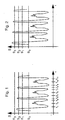
- FIGS. 1 - 4 show received signal profiles of a device operated according to the invention Sensor, which emits pulsed light in the direction of a reflector and receives the reflected pulse light with a photodiode and its Digitized amplitude. The time course of this digitized Amplitudes are shown in Figs. 1-4.
- the sensor for detecting glass bottles used, which transported through the monitoring area of the sensor become.
- Characteristic of translucent glass bottles, in particular Clear glass bottles is that in the area of the bottle edges light passing through the bottle is weakened more than that through the area between the edges because the Attenuation of light in the area of the bottle edges by absorption, Reflection and / or refraction is greater than that between the bottle edges lying area. So when such a glass bottle is on moved past an optical sensor designed as a reflection light barrier is determined by the first in the monitoring area moved bottle edge a relatively strong weakening of the sensor emitted light signal, whereupon less attenuation occurs when the area between the bottle edges in the Monitoring area is moved.
- the first bottle edge of the first bottle leads to a drop in the received signal shown in FIG. 1 at time t 1 , whereupon the area lying between the bottle edges leads to an increase in the received signal at time t 2 .
- the second bottle edge of the first bottle trailing in the conveying direction then again leads to a drop in the received signal at time t 3 .
- a total of four different switching threshold values S 0 , S 1 , S 2 and S 3 are shown in FIG. 1, just like in FIGS. 2-4.
- the highest switching threshold value corresponds to an amplitude which is slightly above the amplitude which the received signal has at times t 4 and t 8 if there is no attenuation of the light sent into the monitoring area.
- the amplitude of the switching threshold S 2 is 92.5% of the amplitude of the switching threshold S 3 .
- the amplitude of the switching threshold value S 1 is 85%, that of the switching threshold value S 0 is 50% of the amplitude of the switching threshold value S 3 .
- a counter n 0 , n 1 , n 2 and n 3 is provided for each switching threshold value S 0 , S 1 , S 2 and S 3 , which counter is incremented by 1 when the received signal corresponds to the corresponding one Threshold exceeded.
- the switching threshold values S 0 , S 1 and S 2 are each exceeded four times, while the switching threshold value S 3 is never exceeded.
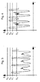
- the signal curve according to FIG. 2 differs from the signal curve according to FIG. 1 in that the switching threshold value S 3 is also exceeded when the spaces are recognized.
- the other switching threshold values or the detection threshold value can then be set according to the percentages already mentioned above, the newly set switching threshold value S 3 (new) being used as the reference variable.
- the switching threshold values or the detection threshold value must be lowered.
- the sensitivity of the for raising and lowering the switching threshold values and the detection threshold of the relevant control loop versus interference can be reduced by using a small gain factor K is set by filtering the control deviation e or by using an I controller.
- the switching threshold value S 0 is 50% of the switching threshold value S 3 .
- the method according to the invention is not only for clear glass detection applicable, but can always be used, for example come when objects are to be recognized which the emitted Only weaken the light and receive light from the sensor not prevent completely.
- objects can also be recognized be the reflector of a reflex light barrier only partially cover.
Description
Die Erfindung betrifft ein Verfahren zum Betrieb eines opto-elektronischen Sensors, insbesondere einer Lichtschranke, bei dem mittels eines Lichtsenders ein Lichtsignal in einen Überwachungsbereich ausgesandt wird und ein zum Empfang von ausgesandten und reflektierten Lichtsignalen ausgelegter Lichtempfänger ein Empfangssignal liefert, dessen Amplitude auf Vorhandensein eines Objekts im Überwachungsbereich untersucht wird, wobei bei Über- oder Unterschreitung eines Erkennungs-Schwellwerts ein Gegenstands-Feststellungssignal abgegeben wird. Ein derartiges Verfahren ist aus EP-A-0 485 857 bekannt.The invention relates to a method for operating an opto-electronic Sensor, in particular a light barrier, in which by means of a light transmitter a light signal is sent to a monitoring area and one for receiving emitted and reflected light signals designed light receiver delivers a received signal, the amplitude checked for the presence of an object in the surveillance area is, when a detection threshold is exceeded or undershot an object detection signal is given. Such a method is known from EP-A-0 485 857.
Für das zufriedenstellende Funktionieren derartiger Verfahren ist es wesentlich, daß der genannte Erkennungs-Schwellwert korrekt eingestellt ist, da bei einer unzureichenden Einstellung des Erkennungs-Schwellwerts nicht ausgeschlossen werden kann, daß ein Gegenstands-feststellungssignal abgegeben wird, obwohl kein Objekt im Überwachungsbereich vorhanden ist oder daß kein Gegenstandsfeststellungssignal abgegeben wird, obwohl ein Objekt im Überwachungsbereich vorhanden ist.It is essential for the satisfactory functioning of such processes that that the detection threshold mentioned is set correctly is because the detection threshold setting is inadequate it cannot be excluded that an object detection signal is delivered, although no object in the surveillance area is present or that there is no object detection signal is delivered even though an object exists in the monitoring area is.
Zur Einstellung des Erkennungs-Schwellwerts ist es bekannt, diesen beispielsweise mittels eines Potentiometers manuell vom Benutzer auf einen geeigneten Wert einstellen zu lassen, wobei ein derartiges manuelles Verfahren naturgemäß mit Ungenauigkeiten behaftet ist. It is known to set the detection threshold value, for example manually by a user using a potentiometer to have a suitable value set, such a manual method is inherently inaccurate.
Weiterhin ist es zumindest gemäß internem Stand der Technik der Anmelderin bekannt, Teach-In-Verfahren einzusetzen, bei denen in den Überwachungsbereich des opto-elektronischen Sensors ein Objekt eingebracht, die dabei empfangene Signalamplitude mit einem Faktor bewertet und gespeichert und dieser gespeicherte Wert als künftiger Erkennungs-Schwellwert verwendet wird.Furthermore, it is at least according to the applicant's internal state of the art known to use teach-in procedures in which in the monitoring area an object is inserted into the optoelectronic sensor, the signal amplitude received is evaluated with a factor and stored and this stored value as the future detection threshold is used.
Letztgenanntes Verfahren besitzt den Nachteil, daß der Aufwand des Einbringens des Objektes in den Überwachungsbereich betrieben werden muß und aufgrund verschiedener Eigenschaften der eingebrachten Objekte, insbesondere aufgrund verschiedener Reflektivitäten, verschiedener Abstände zum Sensor sowie verschiedener geometrischer Formen der Objekte nicht sichergestellt werden kann, daß man im Rahmen des Teach-In-Verfahrens immer den für die Einstellung des Erkennungs-Schwellwerts maßgeblichen Fall erfaßt.The latter method has the disadvantage that the effort involved in introducing it of the object in the surveillance area must and due to different properties of the objects brought in, especially due to different reflectivities, different Distances to the sensor and various geometric shapes of the objects it cannot be guaranteed that one will be in the framework of the teach-in procedure always the one for setting the detection threshold relevant case.
Weiterhin ist es von Nachteil, daß ein einmal festgelegter Erkennungs-Schwellwert während der Betriebszeit des Sensors konstant bleibt und somit betriebsbedingten Lichtleistungsschwankungen, die beispielsweise durch Verschmutzung oder Alterung der Lichtsender bedingt sind, nicht Rechnung tragen kann, so daß es zu Fehlerkennungen von Objekten im Überwachungsbereich kommt.Furthermore, it is disadvantageous that a detection threshold value that has been defined once remains constant during the operating time of the sensor and thus operational light output fluctuations, for example are not caused by dirt or aging of the light transmitter Can take into account, so that there is error detection of objects in the Surveillance area is coming.
Eine Aufgabe der Erfindung besteht darin, ein Verfahren der eingangs genannten Art derart zu verbessern, daß eine möglichst exakte und den tatsächlich gegebenen Betriebsbedingungen Rechnung tragende Festlegung des Erkennungs-Schwellwerts zum Betriebsbeginn möglich wird und/oder daß auch während des Betriebs des Sensors auftretende Lichtleistungs- oder Systemempfindlichkeitsschwankungen auf geeignete Weise kompensiert werden können.An object of the invention is a method of the aforementioned Art to improve in such a way that the most accurate and the actual taking into account the given operating conditions of the detection threshold at the start of operation is possible and / or that light output occurring even during the operation of the sensor or system sensitivity fluctuations are suitably compensated for can be.
Zur Lösung der genannten Aufgaben wird erfindungsgemäß vorgeschlagen, daß mehrere Schalt-Schwellwerte vorgegeben werden, wobei das Über- bzw. Unterschreiten dieser Schalt-Schwellwerte durch das Empfangssignal jeweils ein Schaltsignal auslöst, daß die Anzahl der bezüglich jedes Schalt-Schwellwerts auftretenden Schaltsignale ermittelt wird, und daß der Erkennungs-Schwellwert und die Schalt-Schwellwerte in Abhängigkeit von den ermittelten Anzahlen ein- oder nachgestellt werden.According to the invention, to solve the above-mentioned problems, that several switching threshold values are specified, the The received signal exceeds or falls below these switching threshold values triggers a switching signal that the number of related each switching threshold occurring switching signals is determined, and that the detection threshold and the switching thresholds are dependent can be adjusted or adjusted from the determined numbers.
Die Erfindung macht sich die Erkenntnis zunutze, daß sich die Amplitude des Empfangssignals sowohl beim Vorhandensein von Objekten im Überwachungsbereich als auch bei objektfreiem Überwachungsbereich innerhalb bestimmter Bereiche bewegt. Dadurch, daß die erfindungsgemäß vorgesehenen Schalt-Schwellwerte in diese Bereiche und/oder etwas ober- oder unterhalb dieser Bereiche gelegt werden, kann überprüft werden, ob sich das Empfangssignal in den jeweiligen Betriebssituationen in den erwarteten Bereichen bewegt. Diese Überprüfung erfolgt erfindungsgemäß, in dem gezählt wird, wie oft jeder der definierten Schalt-Schwellwerte vom Empfangssignal über- bzw. unterschritten wird. Es können hierbei beispielsweise Schalt-Schwellwerte definiert werden, die bei einem ordnungsgemäßen Funktionieren des erfindungsgemäßen Sensors niemals über- bzw. unterschritten werden. Weiterhin ist es möglich, zwei Schalt-Schwellwerte so zu definieren, daß sie bei einem ordnungsgemäßen Funktionieren des erfindungsgemäßen Sensors grundsätzlich immer nur gemeinsam über- bzw. unterschritten werden. Wenn dann beispielsweise beim Betrieb des erfindungsgemäßen Sensors der erstgenannte Schalt-Schwellwert über- bzw. unterschritten wird oder von den beiden letztgenannten Schalt-Schwellwerten nur einer über- bzw. unterschritten wird, kann darauf geschlossen werden, daß die Schalt-Schwellwerte nachgestellt werden müssen.The invention makes use of the knowledge that the amplitude of the reception signal both in the presence of objects in the surveillance area as well as with an object-free surveillance area within certain areas moved. The fact that the invention provided switching threshold values in these areas and / or somewhat above or placed below these areas, it can be checked whether the received signal in the respective operating situations in the expected Areas moved. This check is carried out according to the invention, in which is counted how often each of the defined switching threshold values from Received signal is exceeded or fallen below. Here, for example Switching thresholds can be defined when a proper Functioning of the sensor according to the invention never or fall below. It is also possible to set two switching threshold values to be defined in such a way that when it is properly The sensor according to the invention always only works are exceeded or fallen below together. If so, for example when operating the sensor according to the invention, the first-mentioned switching threshold is exceeded or undershot or by the latter two Switching threshold values are only exceeded or undershot, can be concluded that the switching threshold values are adjusted Need to become.
Gemeinsam mit den Schalt-Schwellwerten ist dann auch der Erkennungs-Schwellwert, welcher für die Abgabe eines Gegenstands-Feststellungssignals verantwortlich ist, neu festzulegen, wobei diese Festlegung in Abhängigkeit von den neu eingestellten Schalt-Schwellwerten erfolgt. Zu diesem Zweck kann der Erkennungs-Schwellwert beispielsweise derart definiert sein, daß er immer gleich einem mit einem vorgegebenen Faktor multiplizierten Schalt-Schwellwert ist. Ebenso ist es möglich, einen der Schalt-Schwellwerte direkt als Erkennungs-Schwellwert zu definieren.Together with the switching threshold values, there is also the detection threshold value, which is for the delivery of an object detection signal is responsible to redefine, this down depending on the newly set switching threshold values he follows. For this purpose, the detection threshold can, for example be defined such that it is always the same as a given one Factor multiplied switching threshold is. It is also possible to define one of the switching threshold values directly as a detection threshold value.
Bevorzugt ist es, wenn ein Schalt-Schwellwert der Amplitude des Empfangssignals bei objektfreiem Überwachungsbereich entspricht. Falls das erfindungsgemäße Verfahren bei einer Reflex-Lichtschranke eingesetzt wird, kann dieser Schalt-Schwellwert die höchste Amplitude aller vorgesehenen Schalt-Schwellwerte aufweisen. Dieser Schalt-Schwellwert kann dabei auch einem etwas oberhalb der Amplitude des Empfangssignals bei objektfreiem Überwachungsbereich angesiedelten Wert entsprechen.It is preferred if a switching threshold value of the amplitude of the received signal with object-free surveillance area. If that The inventive method used in a reflex light barrier this switching threshold value can be the highest amplitude of all provided Have switching thresholds. This switching threshold can thereby also a little above the amplitude of the received signal object-free surveillance area.
Von Vorteil ist es, wenn all diejenigen Schalt-Schwellwerte, welche nicht der Amplitude des Empfangssignals bei objektfreiem Überwachungsbereich entsprechen, jeweils einem vorgegebenen Prozentsatz des genannten Schalt-Schwellwerts entsprechen. Diese Prozentsätze liegen bei einer Reflex-Lichtschranke unter 100 %. Somit stehen alle Schalt-Schwellwerte unabhängig von der momentanen konkreten Einstellung in einem konstanten Verhältnis zueinander.It is advantageous if all those switching threshold values that are not the amplitude of the received signal with an object-free monitoring area correspond to a predetermined percentage of the above Switching threshold correspond. These percentages are for a reflex light barrier below 100%. All switching threshold values are thus set regardless of the current concrete setting in a constant Relationship to each other.
Besonders vorteilhaft ist es, wenn vor Inbetriebnahme des Sensors im Rahmen eines Initialisierungsprozesses bei objektfreiem Überwachungsbereich derjenige Schalt-Schwellwert ermittelt wird, dessen Amplitude dem Empfangssignal bei objektfreiem Überwachungsbereich entspricht, wobei die anderen Schalt-Schwellwerte in Abhängigkeit von dem genannten Schalt-Schwellwert berechnet werden, wodurch alle Schalt-Schwellwerte an die während des Initialisierungsprozesses gegebenen Betriebsbedingungen angepaßt werden. Da der Erkennungs-Schwellwert - wie bereits erläutert - in Abhängigkeit von den Schalt-Schwellwerten festgelegt wird, kann auf die genannte Weise sichergestellt werden, daß der Erkennungs-Schwellwert unmittelbar nach dem Initialisierungsprozeß optimal an die gegebenen Betriebsbedingungen angepaßt ist, wodurch das Risiko für Fehlerkennungen deutlich reduziert wird. Zudem ist es erfindungsgemäß möglich, den Initialisierungsprozeß durchzuführen, ohne ein Objekt in den Überwachungsbereich einbringen zu müssen.It is particularly advantageous if, before the sensor is put into operation As part of an initialization process with an object-free surveillance area that switching threshold value is determined, the amplitude of which Received signal corresponds to an object-free monitoring area, where the other switching threshold values depending on the above Switching threshold are calculated, which eliminates all switching thresholds to the operating conditions given during the initialization process be adjusted. Because the detection threshold - as already explained - depending on the switching threshold values, can be ensured in the manner mentioned that the detection threshold immediately after the initialization process is adapted to the given operating conditions, which increases the risk for Error detection is significantly reduced. It is also according to the invention possible to perform the initialization process without an object in to bring in the surveillance area.
Während des Betriebs eines Sensors ist es gemäß der Erfindung vorteilhaft, wenn die ermittelten und jeweils auf die Schalt-Schwellwerte bezogenen Anzahlen der Schaltsignale in Beziehung zueinander oder zu einem vorgegebenen Wert gesetzt und die jeweils gültigen Ist-Beziehungen mit vorgegebenen Soll-Beziehungen verglichen werden, wobei ein Nachstellen der Schalt-Schwellwerte und des Erkennungs-Schwellwertes nur bei einer Abweichung der Ist-Beziehungen von den Soll-Beziehungen erfolgt. In diesem Fall paßt sich der erfindungsgemäß betriebene Sensor während seines Betriebs automatisch an veränderte Betriebsbedingungen an, die beispielsweise durch Temperatur- oder Verschmutzungseffekte hervorgerufen werden.During the operation of a sensor, it is advantageous according to the invention if the determined and in each case related to the switching threshold values Number of switching signals in relation to each other or to one specified value and the respectively valid actual relationships with predefined target relationships are compared, an adjustment the switching threshold values and the detection threshold value only for one The actual relationships deviate from the target relationships. In this Fall adapts the sensor operated according to the invention during its Operating automatically to changed operating conditions, for example caused by temperature or pollution effects become.
Die Schalt-Schwellwerte werden im Rahmen eines Nachstell-Vorgangs bevorzugt so eingestellt, daß die Verhältnisse der Schalt-Schwellwerte zueinander immer konstant bleiben. Dies bedeutet, daß durch einen Nachstell-vorgang beispielsweise mittels eines Regelalgorithmus ein neuer Wert für den höchsten Schalt-Schwellwert berechnet wird, woraufhin alle anderen Schalt-Schwellwerte sowie der Erkennungs-Schwellwert auf neue Werte eingestellt werden, die jeweils einem fest vorgegebenen Prozentsatz des genannten neu justierten Schalt-Schwellwerts entsprechen.The switching threshold values are preferred in the context of an adjustment process set so that the ratios of the switching thresholds to each other always remain constant. This means that through an adjustment process for example using a control algorithm a new value for the highest switching threshold is calculated, whereupon all others Switching threshold values as well as the detection threshold value to new values can be set, each a fixed percentage of the correspond to the newly adjusted switching threshold.
Die auf die Schalt-Schwellwerte bezogenen Anzahlen können jeweils für die Dauer einer vorgegebenen Betriebszeitspanne ermittelt werden, an deren Ende gegebenenfalls ein Nachstellen erfolgt. Das Nachstellen kann während des Sensorbetriebs in einem konstanten Zeitraster wiederholt werden.The numbers relating to the switching threshold values can each be for the duration of a predetermined operating period are determined, at the If necessary, an adjustment is made at the end. The adjustment can repeated during the sensor operation in a constant time pattern become.
Bevorzugt ist es, wenn insgesamt 3 oder 4 unterschiedliche Schalt-Schwellwerte vorgegeben werden, wobei beispielsweise einer dieser Schalt-Schwellwerte als Erkennungs-Schwellwert definiert wird.It is preferred if a total of 3 or 4 different switching threshold values are specified, for example one of these switching threshold values is defined as the detection threshold.
Vorteilhaft ist es, wenn der Lichtsender eines erfindungsgemäß arbeitenden Sensors mit Pulslicht betrieben wird.It is advantageous if the light transmitter works according to the invention Sensor is operated with pulsed light.
Die Erfindung kann bei einer Reflex-Lichtschranke eingesetzt werden, bei der die ausgesandten Lichtsignale bei objektfreiem Überwachungsbereich von einem am dem Sensor gegenüberliegenden Ende des Überwachungsbereichs angeordneten Reflektor zum Lichtempfänger reflektiert werden. Ebenso ist es jedoch auch möglich, die Erfindung beim Betrieb einer Einweg-Lichtschranke einzusetzen.The invention can be used with a reflex light barrier of the emitted light signals with an object-free monitoring area from an end of the monitoring area opposite the sensor arranged reflector to be reflected to the light receiver. However, it is also possible to use the invention when operating a one-way light barrier to use.
Das erfindungsgemäße Verfahren ist bevorzugt zur Klarglaserkennung einsetzbar, was im Rahmen der nachfolgenden Figurenbeschreibung noch näher erläutert wird.The method according to the invention is preferred for clear glass detection can be used, which is still within the scope of the following description of the figures is explained in more detail.
Weitere bevorzugte Ausführungsformen der Erfindung sind in den Unteransprüchen angegeben.Further preferred embodiments of the invention are in the subclaims specified.
Die Erfindung wird nachfolgend anhand eines Ausführungsbeispiels unter Bezugnahme auf die Zeichnungen beschrieben; in diesen zeigen:
- Fig. 1
- den Verlauf eines Empfangssignals mit korrekt eingestellten Schalt-Schwellwerten und korrekt eingestelltem Erkennungs-Schwellwert,
- Fig. 2
- den Verlauf eines Empfangssignals mit zu niedrig eingestellten Schalt-Schwellwerten und zu niedrig eingestelltem Erkennungs-Schwellwert,
- Fig. 3
- den Verlauf eines Empfangssignals mit zu hoch eingestellten Schalt-Schwellwerten und zu hoch eingestelltem Erkennungs-Schwellwert,
- Fig. 4
- den Verlauf eines Empfangssignals in einem Betriebsfall, in dem ein Gegenstandsfeststellungssignal nicht zuverlässig erzeugt werden kann.
- Fig. 1
- the course of a received signal with correctly set switching threshold values and correctly set detection threshold value,
- Fig. 2
- the course of a received signal with switching threshold values set too low and detection threshold value set too low,
- Fig. 3
- the course of a received signal with switching thresholds set too high and detection threshold set too high,
- Fig. 4
- the course of a received signal in an operating case in which an object detection signal cannot be generated reliably.
Die Fig. 1 - 4 zeigen Empfangssignalverläufe eines erfindungsgemäß betriebenen Sensors, welcher Pulslicht in Richtung eines Reflektors aussendet und das reflektierte Pulslicht mit einer Photodiode empfängt und dessen Amplitude digitalisiert. Der zeitliche Verlauf dieser digitalisierten Amplituden ist in den Fig. 1 - 4 dargestellt.1 - 4 show received signal profiles of a device operated according to the invention Sensor, which emits pulsed light in the direction of a reflector and receives the reflected pulse light with a photodiode and its Digitized amplitude. The time course of this digitized Amplitudes are shown in Figs. 1-4.
Gemäß den Fig. 1 - 4 wird der Sensor zur Erkennung von Glasflaschen eingesetzt, welche durch den Überwachungsbereich des Sensors transportiert werden. Charakteristisch für durchscheinende Glasflaschen, insbesondere Klarglasflaschen ist, daß das im Bereich der Flaschenränder durch die Flasche tretende Licht stärker abgeschwächt wird als das durch den zwischen den Rändern liegenden Bereich tretende Licht, da die Dämpfung des Lichtes im Bereich der Flaschenränder durch Absorption, Reflexion und/oder Brechung größer ist als in dem zwischen den Flaschenrändern liegenden Bereich. Wenn also eine solche Glasflasche an einem als Reflektions-Lichtschranke ausgebildeten optischen Sensor vorbeibewegt wird, ergibt sich durch den zuerst in den Überwachungsbereich bewegten Flaschenrand eine relativ starke Abschwächung des vom Sensor ausgesandten Lichtsignals, woraufhin dann eine geringere Abschwächung auftritt, wenn der zwischen den Flaschenrändern liegende Bereich in den Überwachungsbereich bewegt wird. Wenn schließlich nachfolgend der zweite, in Förderrichtung hinten liegende Flaschenrand in den Überwachungsbereich bewegt wird, ergibt sich wiederum eine starke Abschwächung des vom Sensor ausgesandten Lichtsignals. Für jede durch den Überwachungsbereich bewegte Flasche wird somit ein im wesentlichen W-förmiger Empfangssignalverlauf erhalten, wie dieser beispielsweise in Fig. 1 für drei aufeinanderfolgende Flaschen dargestellt ist.1-4, the sensor for detecting glass bottles used, which transported through the monitoring area of the sensor become. Characteristic of translucent glass bottles, in particular Clear glass bottles is that in the area of the bottle edges light passing through the bottle is weakened more than that through the area between the edges because the Attenuation of light in the area of the bottle edges by absorption, Reflection and / or refraction is greater than that between the bottle edges lying area. So when such a glass bottle is on moved past an optical sensor designed as a reflection light barrier is determined by the first in the monitoring area moved bottle edge a relatively strong weakening of the sensor emitted light signal, whereupon less attenuation occurs when the area between the bottle edges in the Monitoring area is moved. When finally the second bottle edge in the direction of conveyance at the back into the monitoring area is moved, there is again a strong weakening of the light signal emitted by the sensor. For everyone through the Monitoring area moving bottle thus becomes essentially one Receive W-shaped received signal waveform, such as this one in Fig. 1 is shown for three successive bottles.
Der erste Flaschenrand der ersten Flasche führt zum Zeitpunkt t1 zu einem Abfall des in Fig. 1 dargestellten Empfangssignals, woraufhin der zwischen den Flaschenrändern liegende Bereich zum Zeitpunkt t2 zu einem Ansteigen des Empfangssignals führt. Der in Förderrichtung nachlaufende zweite Flaschenrand der ersten Flasche führt dann zum Zeitpunkt t3 wiederum zu einem Abfall des Empfangssignals.The first bottle edge of the first bottle leads to a drop in the received signal shown in FIG. 1 at time t 1 , whereupon the area lying between the bottle edges leads to an increase in the received signal at time t 2 . The second bottle edge of the first bottle trailing in the conveying direction then again leads to a drop in the received signal at time t 3 .
Entsprechendes gilt für die Zeitpunkte t5, t6 und t7 bzw. t9, t10 und t11 für die zweite bzw. dritte Flasche, die nach der ersten Flasche in den Überwachungsbereich des Sensors bewegt werden.The same applies to the times t 5 , t 6 and t 7 or t 9 , t 10 and t 11 for the second or third bottle, which are moved into the monitoring area of the sensor after the first bottle.
Zu den Zeitpunkten t4 und t8 erfolgt ein starker Anstieg des Empfangssignals, da der Sensor zu diesem Zeitpunkt den zwischen der ersten und der zweiten bzw. der zweiten und der dritten Flasche bestehenden Zwischenraum "sieht". Wenn sich diese Zwischenräume im Überwachungsbereich befinden, kann der vom Sensor ausgesandte Lichtstrahl direkt zum Reflektor und von diesem zurück zum Sensor gelangen, ohne daß eine Abschwächung durch eine im Überwachungsbereich vorhandene Flasche erfolgt.At times t 4 and t 8 there is a sharp rise in the received signal, since at this time the sensor "sees" the space between the first and the second or the second and the third bottle. If these gaps are in the monitoring area, the light beam emitted by the sensor can go directly to the reflector and from there back to the sensor without being weakened by a bottle present in the monitoring area.
In Fig. 1 sind ebenso wie in den Fig. 2 - 4 insgesamt vier unterschiedliche Schalt-Schwellwerte S0, S1, S2 und S3 eingezeichnet. Der höchste Schalt-Schwellwert entspricht einer Amplitude, die geringfügig über derjenigen Amplitude liegt, die das Empfangssignal zu den Zeitpunkten t4 und t8 aufweist, wenn keine Abschwächung des in den Überwachungsbereich gesandten Lichts erfolgt. Die Amplitude des Schalt-Schwellwerts S2 beträgt 92,5 % der Amplitude des Schalt-Schwellwerts S3. Die Amplitude des Schalt-Schwellwertes S1 beträgt 85 %, diejenige des Schalt-Schwellwertes S0 50 % der Amplitude des Schalt-Schwellwertes S3. Diese prozentualen Verhältnisse gelten sowohl vor als auch nach einem erfindungsgemäßen Nachstellvorgang der Schalt-Schwellwerte, so daß es beispielsweise möglich ist, mittels eines Regelalgorithmus lediglich einen nachgestellten Schalt-Schwellwert S3 zu berechnen und die Schalt-Schwellwerte S0, S1 und S2 entsprechend den genannten Prozentsätzen zu berechnen.A total of four different switching threshold values S 0 , S 1 , S 2 and S 3 are shown in FIG. 1, just like in FIGS. 2-4. The highest switching threshold value corresponds to an amplitude which is slightly above the amplitude which the received signal has at times t 4 and t 8 if there is no attenuation of the light sent into the monitoring area. The amplitude of the switching threshold S 2 is 92.5% of the amplitude of the switching threshold S 3 . The amplitude of the switching threshold value S 1 is 85%, that of the switching threshold value S 0 is 50% of the amplitude of the switching threshold value S 3 . These percentages apply both before and after an adjustment process of the switching threshold values according to the invention, so that it is possible, for example, to calculate only an adjusted switching threshold value S 3 and the switching threshold values S 0 , S 1 and S 2 using a control algorithm to be calculated according to the percentages mentioned.
In einem erfindungsgemäß arbeitenden Sensor wird für jeden Schalt-Schwellwert S0, S1, S2 und S3 jeweils ein Zähler n0, n1, n2 und n3 vorgesehen, welcher jeweils um 1 hochgezählt wird, wenn das Empfangssignal den entsprechenden Schwellwert überschreitet.In a sensor according to the invention, a counter n 0 , n 1 , n 2 and n 3 is provided for each switching threshold value S 0 , S 1 , S 2 and S 3 , which counter is incremented by 1 when the received signal corresponds to the corresponding one Threshold exceeded.
In dem in Fig. 1 gezeigten Beispiel werden die Schalt-Schwellwerte S0, S1
und S2 jeweils viermal überschritten, während der Schalt-Schwellwert S3
keinmal überschritten wird. Nach Empfang des Signals gemäß Fig. 1 würden
also folgenden Zählerstände gelten:
n0 = 4; n1 = 4; n2 = 4; n3 = 0In the example shown in FIG. 1, the switching threshold values S 0 , S 1 and S 2 are each exceeded four times, while the switching threshold value S 3 is never exceeded. After receiving the signal according to FIG. 1, the following counter readings would apply:
n 0 = 4; n 1 = 4; n 2 = 4; n 3 = 0
Beim dargestellten Ausführungsbeispiel kann davon ausgegangen werden,
daß die Schalt-Schwellwerte sowie der Erkennungs-Schwellwert, welcher
gleich S1 ist, korrekt eingestellt sind, wenn gilt:
n3 = 0 und n1 = n2 In the exemplary embodiment shown, it can be assumed that the switching threshold values and the detection threshold value, which is equal to S 1 , are set correctly if:
n 3 = 0 and n 1 = n 2
Vorstehende Bedingung ist gemäß Fig. 1, wenn der zwischen den Zeitpunkten t1 und t11 verstrichene Zeitraum überwacht wird, erfüllt, so daß bei einem Empfangssignalverlauf gemäß Fig. 1 kein Nachstellen der Schalt-Schwellwerte bzw. des Erkennungs-Schwellwerts nötig ist. Gemäß Fig. 1 kann demzufolge immer dann, wenn der Erkennungs-Schwellwert S1 vom Empfangssignal überschritten wird, davon ausgegangen werden, daß sich keine Flasche im Überwachungsbereich des Sensors befindet bzw. daß der Sensor gerade einen zwischen zwei aufeinanderfolgenden Flaschen bestehenden Zwischenraum "sieht".1, if the period elapsed between the times t 1 and t 11 is monitored, the above condition is fulfilled, so that no adjustment of the switching threshold values or the detection threshold value is necessary in the case of a received signal curve according to FIG. 1. According to FIG. 1, therefore, whenever the detection threshold value S 1 is exceeded by the received signal, it can be assumed that there is no bottle in the sensor's monitoring area or that the sensor is "seeing" an intermediate space between two successive bottles. .
Der Signalverlauf gemäß Fig. 2 unterscheidet sich vom Signalverlauf gemäß
Fig. 1 dadurch, daß bei Erkennung der Zwischenräume auch der
Schalt-Schwellwert S3 überschritten wird. Die Zählerstände des Signals
gemäß Fig. 2 sind daher wie folgt:
n0 = 4; n1 = 4; n2 = 4; n3 = 4The signal curve according to FIG. 2 differs from the signal curve according to FIG. 1 in that the switching threshold value S 3 is also exceeded when the spaces are recognized. The counter values of the signal according to FIG. 2 are therefore as follows:
n 0 = 4; n 1 = 4; n 2 = 4; n 3 = 4
Die in Verbindung mit Fig. 1 bereits genannte Soll-Beziehung n3 = 0 ist
somit gemäß Fig. 2 nicht erfüllt, was bedeutet, daß die Schalt-Schwellwerte
angehoben werden müssen. Die für die Anhebung der
Schalt-Schwellwerte maßgebliche Regelabweichung e kann beispielsweise
wie folgt berechnet werden:
Eine neue Schaltschwelle des S3 (neu) kann dann folgendermaßen berechnet
werden:
S3 (neu) = S3 (alt) e K, wobei K einen konstanten Verstärkungsfaktor darstellt.A new switching threshold of the S 3 (new) can then be calculated as follows:
S 3 (new) = S 3 (old) e K, where K represents a constant gain factor.
Die anderen Schalt-Schwellwerte bzw. der Erkennungs-Schwellwert können dann entsprechend den vorstehend bereits genannten Prozentsätzen eingestellt werden, wobei als Bezugsgröße der neu eingestellte Schalt-Schwellwert S3 (neu) herangezogen wird.The other switching threshold values or the detection threshold value can then be set according to the percentages already mentioned above, the newly set switching threshold value S 3 (new) being used as the reference variable.
Das beschriebene Anheben der Schalt-Schwellwerte in einer Betriebssituation gem. Fig. 2 erfolgt immer dann, wenn festgestellt wird, daß in einem vorgegebenen Betriebszeitraum ein Zählerstand n3 > 0 auftritt.The described raising of the switching threshold values in an operating situation according to 2 always occurs when it is determined that a counter reading n 3 > 0 occurs in a given operating period.
Bei einem Empfangs signal verlauf gemäß Fig. 3 ergibt sich folgender Zählerstand:
n0 = 4; n1 = 4; n2 = 0; n3 = 03, the following counter reading is obtained:
n 0 = 4; n 1 = 4; n 2 = 0; n 3 = 0
In diesem Fall ist also die Bedingung n1 = n2 nicht mehr erfüllt, da gilt n2 < n1. In diesem Fall müssen die Schalt-Schwellwerte bzw. der Erkennungs-Schwellwert abgesenkt werden.In this case, the condition n 1 = n 2 is no longer fulfilled, since n 2 <n 1 . In this case, the switching threshold values or the detection threshold value must be lowered.
Die Regelabweichung e für das Absenken kann sich in diesem Fall beispielsweise
wie folgt berechnen:
Die Berechnung des neuen Schalt-Schwellwerts S3 (neu) sowie der anderen neuen Schalt-Schwellwerte und des Erkennungs-Schwellwerts erfolgt analog zu dem Betriebsfall gemäß Fig. 2.The calculation of the new switching threshold value S 3 (new) as well as the other new switching threshold values and the detection threshold value is carried out analogously to the operating case according to FIG. 2.
Die Empfindlichkeit des für das Anheben und Absenken der Schalt-Schwellwerte und des Erkennungs-Schwellwerts maßgeblichen Regelkreises gegenüber Störungen kann reduziert werden, indem ein kleiner Verstärkungsfaktor K eingestellt wird, indem die Regelabweichung e gefiltert wird oder indem ein I-Regler zum Einsatz kommt.The sensitivity of the for raising and lowering the switching threshold values and the detection threshold of the relevant control loop versus interference can be reduced by using a small gain factor K is set by filtering the control deviation e or by using an I controller.
Im Zusammenhang mit Fig. 4 wird nachfolgend die Bedeutung des Schalt-Schwellwerts S0 erläutert, welcher für das Anheben bzw. Absenken der Schalt-Schwellwerte gemäß der Fig. 2 und 3 nicht maßgeblich ist.The meaning of the switching threshold value S 0 is explained below in connection with FIG. 4, which is not decisive for the raising or lowering of the switching threshold values according to FIGS. 2 and 3.
In dem in Fig. 4 dargestellten Ausführungsbeispiel beträgt der Schalt-Schwellwert
S0 50 % des Schalt-Schwellwerts S3. Der Schalt-Schwellwert
S0 wird für die Erzeugung einer Qualitätsaussage bezüglich des von einem
erfindungsgemäß arbeitenden Sensors gelieferten Gegenstandsfeststellungssignsals
herangezogen. Bei dem in Fig. 4 gezeigten Betriebsfall werden
folgende Zählerstände erhalten:
n0 = 12; n1 = 4; n2 = 4; n3 = 0In the embodiment shown in FIG. 4, the switching threshold value S 0 is 50% of the switching threshold value S 3 . The switching threshold value S 0 is used to generate a quality statement regarding the object detection signal supplied by a sensor operating according to the invention. The following counter readings are obtained in the operating case shown in FIG. 4:
n 0 = 12; n 1 = 4; n 2 = 4; n 3 = 0
Immer wenn in einem vorgegebenen Betriebszeitraum der Zählerstand n0 vom Zählerstand n1 abweicht, was gemäß Fig. 4 der Fall ist, kann davon ausgegangen werden, daß die am Sensor vorbeilaufenden Flaschen das ausgesandte Licht nicht hinreichend gut abschwächen, so daß kein zuverlässiges Gegenstands-Feststellungssignal erzeugt werden kann. In dem Whenever the counter reading n 0 deviates from the counter reading n 1 in a given operating period, which is the case according to FIG. 4, it can be assumed that the bottles passing the sensor do not weaken the emitted light sufficiently well, so that no reliable object Detection signal can be generated. By doing
Fig. 4 gezeigten Betriebsfall schwächt der zwischen den Flaschenrändern liegende Bereich das ausgesandte Licht nicht hinreichend ab. In diesem Fall kann bei Nichterfüllung der Bedingung n0 = n1 ein Warnsignal abgegeben werden.4, the area lying between the bottle edges does not sufficiently attenuate the emitted light. In this case, a warning signal can be issued if the condition n 0 = n 1 is not met.
Falls beim erfindungsgemäßen Betrieb eines Sensors aufgrund besonderer Umstände ein automatisches Nachstellen nicht erfolgen kann, beispielsweise im Falle einer sprunghaften, verschmutzungsbedingten Signalreduzierung, kann manuell ein Initialisierungsprozeß ausgelöst werden, auf dessen Basis der weitere einwandfreie Betrieb des Sensors erfolgen kann.If due to special operation of a sensor according to the invention Circumstances an automatic readjustment cannot take place, for example in the event of a sudden, pollution-related signal reduction, an initialization process can be triggered manually the basis of which the further correct operation of the sensor can take place.
Das erfindungsgemäße Verfahren ist nicht nur zur Klarglaserkennung einsetzbar, sondern kann beispielsweise immer dann zur Anwendung kommen, wenn Objekte erkannt werden sollen, welche das ausgesandte Licht lediglich abschwächen und einen Lichtempfang seitens des Sensors nicht vollständig verhindern. So können beispielsweise auch Objekte erkannt werden, die den Reflektor einer Reflex-Lichtschranke nur teilweise abdecken.The method according to the invention is not only for clear glass detection applicable, but can always be used, for example come when objects are to be recognized which the emitted Only weaken the light and receive light from the sensor not prevent completely. For example, objects can also be recognized be the reflector of a reflex light barrier only partially cover.
Claims (11)
- A method of operating an optoelectronic sensor, in particular a light barrier, in which a light signal is sent by means of a light transmitter into a monitored region and a light receiver designed to receive transmitted and reflected light signals, delivers a reception signal, the amplitude of which is investigated for the presence of an object in the monitored region, with an article detection signal being transmitted if a recognition threshold is exceeded or fallen short of,wherein a plurality of switching threshold values are preset, with a switching signal being triggered when the received signal exceeds or falls short of these switching threshold values;wherein the number of the switching signals which arise with respect to each switching threshold is found; andwherein the recognition threshold value and the switching threshold values are set or adjusted in dependence on the numbers found.
- A method in accordance with claim 1 characterized in that a first switching threshold value corresponds to the amplitude of the received signal when the monitored region is free of an object, with in particular all other switching threshold values corresponding to a preset percentage of the first switching threshold value, and/or in that prior to taking the sensor into operation in the context of an initialization process when the monitored region is free of an object, the first switching threshold value is found and the other switching threshold values are calculated in dependence on this switching threshold value, whereby all switching threshold values are matched to the operating conditions given during the initialization process.
- A method in accordance with one of the preceding claims characterized in that the numbers found which respectively relate to the switching threshold values are set into relationship to one another and the respectively valid actual relationships are compared with predetermined desired relationships, with a readjustment only taking place when the actual relationships deviate from the desired relationships, with in particular the ratios of the switching threshold values relative to one another being constant, i.e. not being changed by a readjustment process; and/or in that the numbers related to the switching threshold values are respectively found for the duration of a predetermined operating time interval, at the end of which a readjustment takes place if required and is in particular repeated during the sensor operation in a constant time pattern.
- A method in accordance with one of the preceding claims characterized in that a total of three or four different switching threshold values are preset and, in particular with the provision of three switching threshold values (S1, S2, S3), the relationship S3>S2>S1 applies, with n3, n2 and n1 characterizing the numbers of the switching signals which respectively arise with respect to each switching threshold value within an operating time interval.
- A method in accordance with claim 4 characterized in that the predetermined desired relationships are: n3 = 0 and n1 = n2; and/or in that the switching threshold values and the recognition threshold value are increased when n3 > 0 applies; and/or in that the switching threshold values and the recognition threshold value are lowered when n2 < n1 applies.
- A method in accordance with claim 4 or claim 5 characterized in that a fourth switching threshold value S0 is preset for which S1 > S0 applies, with in particular a warning signal being produced when n0 deviates from n1.
- A method in accordance with one of the preceding claims characterized in that one of the switching threshold values is defined as a recognition threshold value.
- A method in accordance with one of the claims 4, 5 or 6 characterized in that the switching threshold value S1, is defined as a recognition threshold value.
- A method in accordance with one of the preceding claims characterized in that the light transmitter is operated with pulsed light.
- A method in accordance with one of the preceding claims characterized in that in the operation of a reflex light barrier, the transmitted light signals are reflected to the light receiver with an object-free monitored region from a reflector arranged at the end of the monitored region opposite to the sensor.
- Use of a method in accordance with one of the preceding claims for the recognition of clear glass.
Applications Claiming Priority (2)
| Application Number | Priority Date | Filing Date | Title |
|---|---|---|---|
| DE19729638 | 1997-07-10 | ||
| DE19729638A DE19729638A1 (en) | 1997-07-10 | 1997-07-10 | Method for operating an opto-electronic sensor |
Publications (2)
| Publication Number | Publication Date |
|---|---|
| EP0891044A1 EP0891044A1 (en) | 1999-01-13 |
| EP0891044B1 true EP0891044B1 (en) | 2001-03-28 |
Family
ID=7835329
Family Applications (1)
| Application Number | Title | Priority Date | Filing Date |
|---|---|---|---|
| EP98112187A Expired - Lifetime EP0891044B1 (en) | 1997-07-10 | 1998-07-01 | Method for controlling an optoelectronic sensor |
Country Status (4)
| Country | Link |
|---|---|
| US (1) | US6121605A (en) |
| EP (1) | EP0891044B1 (en) |
| JP (1) | JPH11118944A (en) |
| DE (2) | DE19729638A1 (en) |
Cited By (2)
| Publication number | Priority date | Publication date | Assignee | Title |
|---|---|---|---|---|
| EP2226655A1 (en) * | 2009-03-02 | 2010-09-08 | Sick Ag | Optoelectronic sensor |
| EP2520952A2 (en) | 2011-05-05 | 2012-11-07 | Sick AG | Opto-electronic sensor and object detection method |
Families Citing this family (12)
| Publication number | Priority date | Publication date | Assignee | Title |
|---|---|---|---|---|
| DE19954156A1 (en) * | 1999-11-10 | 2001-05-17 | Idm Gmbh Infrarot Sensoren | Photoelectric barrier |
| DE10159932B4 (en) * | 2001-12-06 | 2017-01-26 | Conti Temic Microelectronic Gmbh | Method for correction of stray light in an optical sensor arrangement |
| DE102005019909A1 (en) * | 2005-04-29 | 2006-11-02 | Leuze Electronic Gmbh & Co Kg | Method for operating an optical sensor |
| JP2007139495A (en) * | 2005-11-16 | 2007-06-07 | Keyence Corp | Photoelectric sensor |
| DE102008026603B4 (en) | 2008-05-16 | 2011-06-01 | Leuze Electronic Gmbh & Co Kg | Sensor for detecting objects in a detection area |
| DE102010036883A1 (en) | 2010-08-06 | 2012-02-09 | Sick Ag | Optoelectronic sensor |
| DE102011000931A1 (en) * | 2011-02-25 | 2012-08-30 | Sick Ag | Method for operating a safety light grid and safety light grid |
| ITSA20130008A1 (en) * | 2013-07-10 | 2015-01-11 | Gaetano Giordano | "LIGHT LEVEL SENSOR, WITH NO MODULATED LIGHT, WITH REFERENCE THRESHOLDS WITH DYNAMIC SELF-CALIBRATION AND PROGRAMMABLE HYSTERESIS VALUES" |
| EP3062130B1 (en) | 2015-02-26 | 2022-03-30 | Wincor Nixdorf International GmbH | Method for controlling at least one light barrier, control circuit, and self-service terminal with same |
| DE102017121891A1 (en) * | 2017-09-21 | 2019-03-21 | Sick Ag | Optoelectronic sensor and method for detecting transparent objects |
| EP3499267B1 (en) | 2017-12-13 | 2020-02-19 | Sick Ag | Triangulation light sensor |
| DE202021105507U1 (en) | 2021-10-12 | 2023-01-18 | Leuze Electronic Gmbh + Co. Kg | Photoelectric sensor |
Family Cites Families (11)
| Publication number | Priority date | Publication date | Assignee | Title |
|---|---|---|---|---|
| DE3028942A1 (en) * | 1980-07-30 | 1982-02-18 | Krones Ag Hermann Kronseder Maschinenfabrik, 8402 Neutraubling | METHOD AND INSPECTION DEVICE FOR INSPECTING AN OBJECT, IN PARTICULAR A BOTTLE |
| US4672837A (en) * | 1986-08-01 | 1987-06-16 | Cottrell Jr Walker C | Test system for walk-through metal detector |
| DE3934933A1 (en) * | 1989-10-20 | 1991-04-25 | Pfaff Ag G M | ARRANGEMENT AND METHOD FOR DETECTING A WORKPIECE EDGE |
| DE9010998U1 (en) * | 1990-03-01 | 1990-10-25 | Sartorius Ag, 3400 Goettingen, De | |
| DE4036407C2 (en) * | 1990-11-15 | 1994-06-01 | Telefunken Microelectron | Sensor system |
| DE4125288C2 (en) * | 1991-07-31 | 1995-08-24 | Hansa Metallwerke Ag | Circuit arrangement for the contactless control of a sanitary fitting and method for operating such |
| DE4207772C3 (en) * | 1992-03-11 | 1999-01-21 | Cherry Mikroschalter Gmbh | Sensor switch with size detection |
| DE4228112C1 (en) * | 1992-08-25 | 1993-07-01 | Leuze Electronic Gmbh + Co, 7311 Owen, De | Object detection arrangement - contains light source and receiver, comparator with comparison voltages controlled by micro-controller |
| US5496996A (en) * | 1995-01-24 | 1996-03-05 | Honeywell Inc. | Photoelectric device with capability to change threshold levels in response to changing light intensities |
| DE19525057C1 (en) * | 1995-07-10 | 1997-02-13 | Futronic Gmbh | Light barrier device and method for processing a light sensor output signal |
| DE19530601A1 (en) * | 1995-08-21 | 1997-02-27 | Nsm Ag | Device for checking the function of light barriers |
-
1997
- 1997-07-10 DE DE19729638A patent/DE19729638A1/en not_active Withdrawn
-
1998
- 1998-07-01 DE DE59800572T patent/DE59800572D1/en not_active Expired - Lifetime
- 1998-07-01 EP EP98112187A patent/EP0891044B1/en not_active Expired - Lifetime
- 1998-07-08 US US09/111,176 patent/US6121605A/en not_active Expired - Fee Related
- 1998-07-10 JP JP19519098A patent/JPH11118944A/en active Pending
Cited By (4)
| Publication number | Priority date | Publication date | Assignee | Title |
|---|---|---|---|---|
| EP2226655A1 (en) * | 2009-03-02 | 2010-09-08 | Sick Ag | Optoelectronic sensor |
| US8324557B2 (en) | 2009-03-02 | 2012-12-04 | Sick Ag | Optoelectronic sensor for the detection of pallets |
| EP2520952A2 (en) | 2011-05-05 | 2012-11-07 | Sick AG | Opto-electronic sensor and object detection method |
| DE102011050119A1 (en) | 2011-05-05 | 2012-11-08 | Sick Ag | Optoelectronic sensor and method for object detection |
Also Published As
| Publication number | Publication date |
|---|---|
| EP0891044A1 (en) | 1999-01-13 |
| US6121605A (en) | 2000-09-19 |
| JPH11118944A (en) | 1999-04-30 |
| DE19729638A1 (en) | 1999-01-14 |
| DE59800572D1 (en) | 2001-05-03 |
Similar Documents
| Publication | Publication Date | Title |
|---|---|---|
| EP0891044B1 (en) | Method for controlling an optoelectronic sensor | |
| EP0503040B1 (en) | Optical sensor device and process for operating the same | |
| EP1544643B1 (en) | Method and device for the surveillance of an area with several light emitters arranged side by side | |
| EP0269902B1 (en) | Process and device for measuring the distance between two objects, in particular between vehicles | |
| EP2492714B1 (en) | Method for operating a safety light grid and safety light grid | |
| DE4312186C2 (en) | Methods and devices for determining objects present in a surveillance area and / or for determining their position | |
| DE3603568C2 (en) | ||
| CH681756A5 (en) | ||
| DE19828000C2 (en) | Method for optoelectronic monitoring of a protected area | |
| EP0080073A2 (en) | Method and apparatus for controlling the degree of filling of cigarette ends | |
| DE19951557B4 (en) | Optoelectronic device | |
| WO1993010469A1 (en) | Ultrasonic distance-measuring equipment | |
| EP1853942B1 (en) | Method for operating an optoelectronic sensor | |
| DE19537615B4 (en) | Method for operating an optical light scanner | |
| EP0875775A2 (en) | Method of operating an opto-electronic sensor | |
| DE2529589C2 (en) | Electronic security system with a signal detector circuit | |
| EP2693231A1 (en) | Method and device for evaluating a received change signal | |
| DE19852173C2 (en) | light sensor | |
| DE19745493A1 (en) | Proximity sensor and person recognition method | |
| DE4228112C1 (en) | Object detection arrangement - contains light source and receiver, comparator with comparison voltages controlled by micro-controller | |
| EP0857982B1 (en) | Method and device for distance determination between vehicle and obstacle | |
| DE19747248A1 (en) | Light barrier to detect and identify objects | |
| DE19715146B4 (en) | Procedure for the automatic setting of a switching threshold for a switching sensor | |
| DE2532223A1 (en) | DISCRIMINATOR CIRCUIT | |
| DE3027283C2 (en) |
Legal Events
| Date | Code | Title | Description |
|---|---|---|---|
| PUAI | Public reference made under article 153(3) epc to a published international application that has entered the european phase |
Free format text: ORIGINAL CODE: 0009012 |
|
| AK | Designated contracting states |
Kind code of ref document: A1 Designated state(s): CH DE FR IT LI |
|
| AX | Request for extension of the european patent |
Free format text: AL;LT;LV;MK;RO;SI |
|
| 17P | Request for examination filed |
Effective date: 19990305 |
|
| AKX | Designation fees paid |
Free format text: CH DE FR IT LI |
|
| GRAG | Despatch of communication of intention to grant |
Free format text: ORIGINAL CODE: EPIDOS AGRA |
|
| GRAG | Despatch of communication of intention to grant |
Free format text: ORIGINAL CODE: EPIDOS AGRA |
|
| 17Q | First examination report despatched |
Effective date: 20000621 |
|
| GRAG | Despatch of communication of intention to grant |
Free format text: ORIGINAL CODE: EPIDOS AGRA |
|
| GRAH | Despatch of communication of intention to grant a patent |
Free format text: ORIGINAL CODE: EPIDOS IGRA |
|
| GRAH | Despatch of communication of intention to grant a patent |
Free format text: ORIGINAL CODE: EPIDOS IGRA |
|
| GRAA | (expected) grant |
Free format text: ORIGINAL CODE: 0009210 |
|
| AK | Designated contracting states |
Kind code of ref document: B1 Designated state(s): CH DE FR IT LI |
|
| REG | Reference to a national code |
Ref country code: CH Ref legal event code: EP |
|
| REF | Corresponds to: |
Ref document number: 59800572 Country of ref document: DE Date of ref document: 20010503 |
|
| ET | Fr: translation filed | ||
| ITF | It: translation for a ep patent filed |
Owner name: MARCHI & PARTNERS S.R.L. |
|
| PLBE | No opposition filed within time limit |
Free format text: ORIGINAL CODE: 0009261 |
|
| STAA | Information on the status of an ep patent application or granted ep patent |
Free format text: STATUS: NO OPPOSITION FILED WITHIN TIME LIMIT |
|
| 26N | No opposition filed | ||
| PGFP | Annual fee paid to national office [announced via postgrant information from national office to epo] |
Ref country code: IT Payment date: 20070726 Year of fee payment: 10 |
|
| PGFP | Annual fee paid to national office [announced via postgrant information from national office to epo] |
Ref country code: FR Payment date: 20070718 Year of fee payment: 10 |
|
| REG | Reference to a national code |
Ref country code: FR Ref legal event code: ST Effective date: 20090331 |
|
| PG25 | Lapsed in a contracting state [announced via postgrant information from national office to epo] |
Ref country code: IT Free format text: LAPSE BECAUSE OF NON-PAYMENT OF DUE FEES Effective date: 20080701 Ref country code: FR Free format text: LAPSE BECAUSE OF NON-PAYMENT OF DUE FEES Effective date: 20080731 |
|
| PGFP | Annual fee paid to national office [announced via postgrant information from national office to epo] |
Ref country code: CH Payment date: 20160726 Year of fee payment: 19 |
|
| PGFP | Annual fee paid to national office [announced via postgrant information from national office to epo] |
Ref country code: DE Payment date: 20170724 Year of fee payment: 20 |
|
| REG | Reference to a national code |
Ref country code: CH Ref legal event code: PL |
|
| PG25 | Lapsed in a contracting state [announced via postgrant information from national office to epo] |
Ref country code: CH Free format text: LAPSE BECAUSE OF NON-PAYMENT OF DUE FEES Effective date: 20170731 Ref country code: LI Free format text: LAPSE BECAUSE OF NON-PAYMENT OF DUE FEES Effective date: 20170731 |
|
| REG | Reference to a national code |
Ref country code: DE Ref legal event code: R071 Ref document number: 59800572 Country of ref document: DE |