EP0891025A2 - In einem Flugzeug eingebauter chemischer Hochenergie Laser auf Jod- und Sauerstoff-Basis (COIL) - Google Patents
In einem Flugzeug eingebauter chemischer Hochenergie Laser auf Jod- und Sauerstoff-Basis (COIL) Download PDFInfo
- Publication number
- EP0891025A2 EP0891025A2 EP98111900A EP98111900A EP0891025A2 EP 0891025 A2 EP0891025 A2 EP 0891025A2 EP 98111900 A EP98111900 A EP 98111900A EP 98111900 A EP98111900 A EP 98111900A EP 0891025 A2 EP0891025 A2 EP 0891025A2
- Authority
- EP
- European Patent Office
- Prior art keywords
- photon
- singlet
- delta oxygen
- photon generating
- chemical laser
- Prior art date
- Legal status (The legal status is an assumption and is not a legal conclusion. Google has not performed a legal analysis and makes no representation as to the accuracy of the status listed.)
- Withdrawn
Links
- 239000000126 substance Substances 0.000 title claims abstract description 62
- PRXLCSIMRQFQMX-UHFFFAOYSA-N [O].[I] Chemical compound [O].[I] PRXLCSIMRQFQMX-UHFFFAOYSA-N 0.000 title description 11
- QVGXLLKOCUKJST-UHFFFAOYSA-N atomic oxygen Chemical compound [O] QVGXLLKOCUKJST-UHFFFAOYSA-N 0.000 claims description 78
- MHAJPDPJQMAIIY-UHFFFAOYSA-N Hydrogen peroxide Chemical compound OO MHAJPDPJQMAIIY-UHFFFAOYSA-N 0.000 claims description 72
- 239000001301 oxygen Substances 0.000 claims description 63
- 229910052760 oxygen Inorganic materials 0.000 claims description 63
- ZAMOUSCENKQFHK-UHFFFAOYSA-N Chlorine atom Chemical compound [Cl] ZAMOUSCENKQFHK-UHFFFAOYSA-N 0.000 claims description 32
- 239000000460 chlorine Substances 0.000 claims description 32
- 229910052801 chlorine Inorganic materials 0.000 claims description 32
- 239000000376 reactant Substances 0.000 claims description 22
- 239000007788 liquid Substances 0.000 claims description 18
- XLYOFNOQVPJJNP-UHFFFAOYSA-N water Substances O XLYOFNOQVPJJNP-UHFFFAOYSA-N 0.000 claims description 16
- 238000002156 mixing Methods 0.000 claims description 15
- 239000007789 gas Substances 0.000 claims description 14
- 238000011084 recovery Methods 0.000 claims description 12
- QGZKDVFQNNGYKY-UHFFFAOYSA-N Ammonia Chemical compound N QGZKDVFQNNGYKY-UHFFFAOYSA-N 0.000 claims description 10
- 239000000446 fuel Substances 0.000 claims description 8
- 239000000243 solution Substances 0.000 claims description 8
- 239000007795 chemical reaction product Substances 0.000 claims description 7
- WMFOQBRAJBCJND-UHFFFAOYSA-M Lithium hydroxide Chemical compound [Li+].[OH-] WMFOQBRAJBCJND-UHFFFAOYSA-M 0.000 claims description 6
- KWYUFKZDYYNOTN-UHFFFAOYSA-M Potassium hydroxide Chemical compound [OH-].[K+] KWYUFKZDYYNOTN-UHFFFAOYSA-M 0.000 claims description 6
- HEMHJVSKTPXQMS-UHFFFAOYSA-M Sodium hydroxide Chemical compound [OH-].[Na+] HEMHJVSKTPXQMS-UHFFFAOYSA-M 0.000 claims description 6
- 239000004033 plastic Substances 0.000 claims description 6
- 229920003023 plastic Polymers 0.000 claims description 6
- 238000006243 chemical reaction Methods 0.000 claims description 5
- 229920000049 Carbon (fiber) Polymers 0.000 claims description 4
- 239000004697 Polyetherimide Substances 0.000 claims description 4
- CREMABGTGYGIQB-UHFFFAOYSA-N carbon carbon Chemical compound C.C CREMABGTGYGIQB-UHFFFAOYSA-N 0.000 claims description 4
- 239000011203 carbon fibre reinforced carbon Substances 0.000 claims description 4
- 229920001601 polyetherimide Polymers 0.000 claims description 4
- 230000003628 erosive effect Effects 0.000 claims description 2
- 238000002347 injection Methods 0.000 claims description 2
- 239000007924 injection Substances 0.000 claims description 2
- 239000002131 composite material Substances 0.000 claims 1
- 239000012530 fluid Substances 0.000 claims 1
- 238000009826 distribution Methods 0.000 description 25
- ZCYVEMRRCGMTRW-UHFFFAOYSA-N 7553-56-2 Chemical compound [I] ZCYVEMRRCGMTRW-UHFFFAOYSA-N 0.000 description 16
- KZBUYRJDOAKODT-UHFFFAOYSA-N Chlorine Chemical compound ClCl KZBUYRJDOAKODT-UHFFFAOYSA-N 0.000 description 16
- 230000003287 optical effect Effects 0.000 description 12
- 229910052740 iodine Inorganic materials 0.000 description 11
- 239000011630 iodine Substances 0.000 description 11
- 229910021529 ammonia Inorganic materials 0.000 description 4
- 239000001307 helium Substances 0.000 description 4
- 229910052734 helium Inorganic materials 0.000 description 4
- SWQJXJOGLNCZEY-UHFFFAOYSA-N helium atom Chemical compound [He] SWQJXJOGLNCZEY-UHFFFAOYSA-N 0.000 description 4
- 239000004215 Carbon black (E152) Substances 0.000 description 3
- 239000002826 coolant Substances 0.000 description 3
- 230000007123 defense Effects 0.000 description 3
- 239000002657 fibrous material Substances 0.000 description 3
- 229930195733 hydrocarbon Natural products 0.000 description 3
- 150000002430 hydrocarbons Chemical class 0.000 description 3
- 239000000463 material Substances 0.000 description 3
- 238000000034 method Methods 0.000 description 3
- 230000036961 partial effect Effects 0.000 description 3
- 230000008901 benefit Effects 0.000 description 2
- 230000015556 catabolic process Effects 0.000 description 2
- 238000001816 cooling Methods 0.000 description 2
- 238000006731 degradation reaction Methods 0.000 description 2
- 238000010438 heat treatment Methods 0.000 description 2
- 238000002955 isolation Methods 0.000 description 2
- 238000004064 recycling Methods 0.000 description 2
- 230000002829 reductive effect Effects 0.000 description 2
- 238000003860 storage Methods 0.000 description 2
- 238000009827 uniform distribution Methods 0.000 description 2
- 238000011144 upstream manufacturing Methods 0.000 description 2
- QGZKDVFQNNGYKY-UHFFFAOYSA-O Ammonium Chemical compound [NH4+] QGZKDVFQNNGYKY-UHFFFAOYSA-O 0.000 description 1
- MYMOFIZGZYHOMD-UHFFFAOYSA-N Dioxygen Chemical compound O=O MYMOFIZGZYHOMD-UHFFFAOYSA-N 0.000 description 1
- UFHFLCQGNIYNRP-UHFFFAOYSA-N Hydrogen Chemical compound [H][H] UFHFLCQGNIYNRP-UHFFFAOYSA-N 0.000 description 1
- BQCADISMDOOEFD-UHFFFAOYSA-N Silver Chemical compound [Ag] BQCADISMDOOEFD-UHFFFAOYSA-N 0.000 description 1
- 230000006978 adaptation Effects 0.000 description 1
- 239000003963 antioxidant agent Substances 0.000 description 1
- 230000003078 antioxidant effect Effects 0.000 description 1
- 239000003054 catalyst Substances 0.000 description 1
- 239000011248 coating agent Substances 0.000 description 1
- 238000000576 coating method Methods 0.000 description 1
- 230000001427 coherent effect Effects 0.000 description 1
- 238000002485 combustion reaction Methods 0.000 description 1
- 238000009833 condensation Methods 0.000 description 1
- 230000005494 condensation Effects 0.000 description 1
- 230000009849 deactivation Effects 0.000 description 1
- 230000003247 decreasing effect Effects 0.000 description 1
- 238000011161 development Methods 0.000 description 1
- 238000010586 diagram Methods 0.000 description 1
- 238000009792 diffusion process Methods 0.000 description 1
- 238000010494 dissociation reaction Methods 0.000 description 1
- 230000005593 dissociations Effects 0.000 description 1
- 239000011152 fibreglass Substances 0.000 description 1
- 230000004907 flux Effects 0.000 description 1
- 239000001257 hydrogen Substances 0.000 description 1
- 229910052739 hydrogen Inorganic materials 0.000 description 1
- 239000011261 inert gas Substances 0.000 description 1
- 230000004941 influx Effects 0.000 description 1
- 238000009413 insulation Methods 0.000 description 1
- 230000000670 limiting effect Effects 0.000 description 1
- 238000012423 maintenance Methods 0.000 description 1
- 238000004519 manufacturing process Methods 0.000 description 1
- 239000007769 metal material Substances 0.000 description 1
- 238000012986 modification Methods 0.000 description 1
- 230000004048 modification Effects 0.000 description 1
- 238000010525 oxidative degradation reaction Methods 0.000 description 1
- 238000001556 precipitation Methods 0.000 description 1
- 230000008569 process Effects 0.000 description 1
- 239000000047 product Substances 0.000 description 1
- 239000003507 refrigerant Substances 0.000 description 1
- 238000011160 research Methods 0.000 description 1
- 239000011347 resin Substances 0.000 description 1
- 229920005989 resin Polymers 0.000 description 1
- 150000003839 salts Chemical class 0.000 description 1
- 238000010008 shearing Methods 0.000 description 1
- 239000004332 silver Substances 0.000 description 1
- 229910052709 silver Inorganic materials 0.000 description 1
- 238000007711 solidification Methods 0.000 description 1
- 230000008023 solidification Effects 0.000 description 1
- 230000006641 stabilisation Effects 0.000 description 1
- 238000011105 stabilization Methods 0.000 description 1
- 229920001169 thermoplastic Polymers 0.000 description 1
- 239000004416 thermosoftening plastic Substances 0.000 description 1
- 239000006200 vaporizer Substances 0.000 description 1
Images


Classifications
-
- F—MECHANICAL ENGINEERING; LIGHTING; HEATING; WEAPONS; BLASTING
- F41—WEAPONS
- F41H—ARMOUR; ARMOURED TURRETS; ARMOURED OR ARMED VEHICLES; MEANS OF ATTACK OR DEFENCE, e.g. CAMOUFLAGE, IN GENERAL
- F41H13/00—Means of attack or defence not otherwise provided for
- F41H13/0043—Directed energy weapons, i.e. devices that direct a beam of high energy content toward a target for incapacitating or destroying the target
- F41H13/005—Directed energy weapons, i.e. devices that direct a beam of high energy content toward a target for incapacitating or destroying the target the high-energy beam being a laser beam
- F41H13/0062—Directed energy weapons, i.e. devices that direct a beam of high energy content toward a target for incapacitating or destroying the target the high-energy beam being a laser beam causing structural damage to the target
-
- F—MECHANICAL ENGINEERING; LIGHTING; HEATING; WEAPONS; BLASTING
- F41—WEAPONS
- F41H—ARMOUR; ARMOURED TURRETS; ARMOURED OR ARMED VEHICLES; MEANS OF ATTACK OR DEFENCE, e.g. CAMOUFLAGE, IN GENERAL
- F41H11/00—Defence installations; Defence devices
- F41H11/02—Anti-aircraft or anti-guided missile or anti-torpedo defence installations or systems
-
- H—ELECTRICITY
- H01—ELECTRIC ELEMENTS
- H01S—DEVICES USING THE PROCESS OF LIGHT AMPLIFICATION BY STIMULATED EMISSION OF RADIATION [LASER] TO AMPLIFY OR GENERATE LIGHT; DEVICES USING STIMULATED EMISSION OF ELECTROMAGNETIC RADIATION IN WAVE RANGES OTHER THAN OPTICAL
- H01S3/00—Lasers, i.e. devices using stimulated emission of electromagnetic radiation in the infrared, visible or ultraviolet wave range
- H01S3/005—Optical devices external to the laser cavity, specially adapted for lasers, e.g. for homogenisation of the beam or for manipulating laser pulses, e.g. pulse shaping
- H01S3/0071—Beam steering, e.g. whereby a mirror outside the cavity is present to change the beam direction
-
- H—ELECTRICITY
- H01—ELECTRIC ELEMENTS
- H01S—DEVICES USING THE PROCESS OF LIGHT AMPLIFICATION BY STIMULATED EMISSION OF RADIATION [LASER] TO AMPLIFY OR GENERATE LIGHT; DEVICES USING STIMULATED EMISSION OF ELECTROMAGNETIC RADIATION IN WAVE RANGES OTHER THAN OPTICAL
- H01S3/00—Lasers, i.e. devices using stimulated emission of electromagnetic radiation in the infrared, visible or ultraviolet wave range
- H01S3/05—Construction or shape of optical resonators; Accommodation of active medium therein; Shape of active medium
- H01S3/08—Construction or shape of optical resonators or components thereof
- H01S3/081—Construction or shape of optical resonators or components thereof comprising three or more reflectors
- H01S3/0818—Unstable resonators
-
- H—ELECTRICITY
- H01—ELECTRIC ELEMENTS
- H01S—DEVICES USING THE PROCESS OF LIGHT AMPLIFICATION BY STIMULATED EMISSION OF RADIATION [LASER] TO AMPLIFY OR GENERATE LIGHT; DEVICES USING STIMULATED EMISSION OF ELECTROMAGNETIC RADIATION IN WAVE RANGES OTHER THAN OPTICAL
- H01S3/00—Lasers, i.e. devices using stimulated emission of electromagnetic radiation in the infrared, visible or ultraviolet wave range
- H01S3/09—Processes or apparatus for excitation, e.g. pumping
- H01S3/095—Processes or apparatus for excitation, e.g. pumping using chemical or thermal pumping
-
- H—ELECTRICITY
- H01—ELECTRIC ELEMENTS
- H01S—DEVICES USING THE PROCESS OF LIGHT AMPLIFICATION BY STIMULATED EMISSION OF RADIATION [LASER] TO AMPLIFY OR GENERATE LIGHT; DEVICES USING STIMULATED EMISSION OF ELECTROMAGNETIC RADIATION IN WAVE RANGES OTHER THAN OPTICAL
- H01S3/00—Lasers, i.e. devices using stimulated emission of electromagnetic radiation in the infrared, visible or ultraviolet wave range
- H01S3/23—Arrangements of two or more lasers not provided for in groups H01S3/02 - H01S3/22, e.g. tandem arrangements of separate active media
- H01S3/2383—Parallel arrangements
Definitions
- This invention relates generally to chemical lasers and, specifically, to high energy chemical oxygen iodine lasers.
- Prior art anti-theater ballistic missile weapons lack the capability to interdict theater ballistic missiles before booster rocket burn-out, and have therefore proven to be largely ineffective in destroying even the current generation of theater ballistic missiles.
- an anti-theater ballistic missile system capable of interdicting theater ballistic missiles during the short period of time between missile launch and booster rocket burn-out.
- the invention satisfies this need.
- the invention is a high energy chemical laser installable in an airborne anti-theater ballistic missile system.
- the chemical laser comprises a bank of two or more individual photon generating modules, each module having a distinct photon generating chamber.
- Each of the photon generating chambers are optically inter-connected by a common optical cavity so that total photon output of the chemical laser is the sum of the photon outputs from each of the photon generating modules.
- the chemical laser is a chemical oxygen iodine laser ("COIL").
- COIL chemical oxygen iodine laser
- the COIL has a singlet-delta oxygen generating section, photon generating chamber and pressure recovery section, all specially designed to maximize efficiency and minimize size and weight.
- the invention has been found to provide an effective anti-theater ballistic missile system capable of interdicting and destroying theater ballistic missiles within the short period of time between missile take-off and booster rocket burn-out.
- the invention is a high power chemical laser suitable for use in an airborne anti-theater ballistic missile system.
- a fundamental characteristic of the chemical laser of the invention is that it is comprised of a bank of two or more individual photon generating modules, each module having a distinct photon generating chamber. All of the photon generating chambers from all of the photon generating modules are optically connected by a common optical cavity so that the total photon output of the chemical laser is the sum of the photon outputs from each of the photon generating modules. Use of a common optical cavity also assures coherent optical output.
- the chemical laser is a chemical oxygen iodine laser, also known as a "COIL".
- COIL chemical oxygen iodine laser
- the basic operation of a COIL is generally known in the art and is specifically described in co-pending U.S. Patent Application Serial Nos. 08/762,180 and (entitled “Water Vapor Trap and Liquid Separator for Singlet-Delta Oxygen Generator,” filed concurrently herewith) both of which are incorporated herein by this reference.
- singlet-delta oxygen 12 is produced in a singlet-delta oxygen generator 14 by a reaction of chlorine gas 16 with basic hydrogen peroxide 18 .
- the singlet-delta oxygen 12 is reacted with iodine 20 in a photon generating chamber 22 to produce electronically excited iodine.
- iodine 20 in a photon generating chamber 22 to produce electronically excited iodine.
- high energy photons are released.
- These photons are captured, focused, and then directed via a common optical cavity 24 along a laser beam path 26 to be joined by the photon beams generated by other photon generating modules 8 .
- the photon generating chamber 22 is operated at reduced pressure. Accordingly, the effluent 27 from the photon generating chamber 22 must be drawn from the photon generating chamber 22 by a pressure recovery system 28 .
- the pressure recovery system 28 comprises a diffusion chamber 29 and a plurality of single stage ejectors 30 .
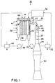
- a preferred singlet-delta oxygen generator 14 useable in the invention is shown generally in Figure 2.
- Chlorine gas 16 typically diluted with helium or other inert gas, is flowed from a chlorine distribution chamber 38 and contacted with basic hydrogen peroxide 18 under conditions well-known in the art to produce singlet-delta oxygen molecules 12 .
- a preferred singlet-delta oxygen generator 14 useable in the invention is described in U.S. Patent No. 5,392,988, the entirety of which is incorporated herein by this reference.
- the basic hydrogen peroxide 18 is introduced into the generator 14 as highly uniform droplets 34 having a nominal diameter between about 300 and 400 microns. These droplets 34 form a falling droplet zone 36 within the generator 14 .
- Chlorine gas 32 is introduced from a chlorine distribution chamber 38 into the falling droplet zone 36 .
- the chlorine gas 16 is directed horizontally, transverse to the downwardly falling droplets 34 .
- a resulting stream containing singlet-delta oxygen 12 is extracted from a singlet-delta oxygen outlet nozzle 40 disposed opposite to the chlorine distribution chamber 38 .
- the basic hydrogen peroxide 18 is removed via a basic hydrogen peroxide catch basin 42 at the bottom of the singlet-delta oxygen generator 14 and is pumped by a basic hydrogen peroxide pump 32 back to a droplet generator 44 at the top of the singlet-delta oxygen generator 14 .
- the recycled basic hydrogen peroxide 18 is cooled in a basic hydrogen peroxide heat exchanger 46 .
- the particular make-up of the basic hydrogen peroxide solution 18 is chosen so as to allow the repeated recycling of the solution 18 with only gradual decrease in singlet-delta oxygen production.
- One preferred basic hydrogen peroxide solution 18 is described in U.S. Patent Application Serial No. 08/762,180, the entirety of which is incorporated herein by this reference.
- U.S. Patent Application Serial No. 08/762,180 there is described a basic hydrogen peroxide solution 18 comprising at least two different bases in molar ratios to one another of between about 3:1 and about 1:1.
- the solution 18 comprises sodium hydroxide, potassium hydroxide and lithium hydroxide.
- Such preferred basic hydrogen peroxide solutions 18 have been found to have significant increased efficiency over prior art basic hydrogen solutions because of their decreased propensity for forming insoluble salts, thereby allowing the continued utilization of a very high percentage of the hydrogen peroxide 18 in the generation of singlet-delta oxygen.
- the use of such a preferred basic hydrogen peroxide solution 18 significantly lengthens the ability of an airborne anti-theater ballistic missile system to remain on station.
- Such preferred basic hydrogen peroxide solutions 18 also have been found to exhibit consistently low viscosity characteristics.
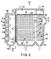
- novel chlorine distribution equipment described in co-pending U.S. Patent Application Serial No. (entitled “Improved Singlet-Delta Oxygen Generator,” filed concurrently herewith and incorporated herein in its entirety by this reference) is used to provide a singlet-delta oxygen generator 14 of higher efficiency than prior art singlet-delta oxygen generators.
- novel chlorine distribution equipment liquid carry-over from the chlorine distribution chamber 38 is minimized and more uniform chlorine distribution into the falling droplet zone 36 is provided.
- Such novel chlorine distribution equipment is shown in Figures 2-5.
- Chlorine 16 is delivered into the chlorine distribution chamber 38 by chlorine inlet conduits 48 which direct the incoming flow of chlorine 16 to impinge against a sidewall 50 of the chlorine distribution chamber 38 disposed opposite a chlorine distribution plate 52 .
- the chlorine distribution plate 52 is a plate sufficiently thin to prevent the puddling of liquid within a plurality of holes 54 within the distribution plate 52 .
- impingement plates 56 are disposed in front of each hole 54 within the chlorine distribution plate 52 to further minimize the back flow of liquid from the falling droplet zone 36 into the chlorine distribution chamber 38 and to cause the lateral flow of chlorine 16 into the falling droplet zone 3 6 to spread through the falling droplet zone 36 in a highly uniform manner.
- the generator 14 further comprises a water vapor trap 60 which removes water vapor from the flow of singlet-delta oxygen 12.
- a preferred embodiment of such a water trap 60 comprises the contacting of the flow stream containing the singlet-delta oxygen molecules 12 with droplets of liquid hydrogen peroxide 62 which has been chilled to temperatures below about -20°C, preferably below about -30°F or lower.
- Such a water trap 60 is described in detail in co-pending U.S. Patent Application Serial No. (entitled “Water Vapor Trap and Liquid Separator for Singlet Oxygen Generator,” filed concurrently herewith and incorporated herein in its entirety by this reference).
- the singlet-delta oxygen generator 14 comprises a series of vertical flow baffles 64 disposed within the path of the stream of singlet-delta oxygen molecules 12 downstream of the water trap 60 .
- flow baffles 64 By the use of such flow baffles 64 , entrained liquid droplets 66 within the stream of singlet-delta oxygen 12 are removed to the bottom of the singlet-delta oxygen generator 14 .
- a chilled hydrogen peroxide retaining sump 68 is disposed to catch chilled hydrogen peroxide from the water trap 60 . From the hydrogen peroxide retaining sump 68 , the hydrogen peroxide is recycled via a water trap recycle pump 70 , chilled in a water trap heat exchanger 72 and delivered anew to a droplet generator 74 disposed at the top of the singlet-delta oxygen generator 14 .
- all pumps in the COIL are gas turbine pumps (“turbo pump”), driven by jet fuel combustion products.
- turbo pump gas turbine pumps
- the use of such turbo pumps in the invention further minimizes the weight requirement of the invention.
- care must be taken to minimize the generation of hydrogen peroxide bubbles within the recycled hydrogen peroxide stream.
- Use of pump impellers designed to provide minimum shearing of the pump liquid is therefore preferred.
- the basic hydrogen peroxide recycle heat exchanger 46 and the water trap heat exchanger 72 use flashing ammonium as the cooling agent.
- flashing ammonia provides a high degree of cooling with minimum weight requirements. Liquid ammonia is stored within the aircraft, is flashed to provide cooling with the heat exchangers and is then expelled to the atmosphere. No cumbersome refrigerant recycle equipment is necessary.
- singlet-delta oxygen 12 generated in a singlet-delta oxygen generator 14 is delivered to the photon generating chamber 22 where it is contacted with gaseous iodine 20 to produce electronically excited iodine.
- the mixing of the singlet-delta oxygen 12 and the gaseous iodine 20 is carried out in chemical reactant mixing nozzles 78 disposed at the inlet to the photon generating chamber 22 .
- chemical reactant mixing nozzles 78 are made from a plastic material, such as a thermoplastic or high-temperature fiberglass resin, which is substantially resistant to chemical and erosive attack at reactant mixing conditions.
- the plastic is polyetherimide.
- Such preferred chemical reactant mixing nozzles are described in detail in co-pending U.S. Patent Application Serial No. (entitled “Gain Generator for High-Energy Chemical Laser,” filed concurrently herewith and incorporated herein in its entirety by this reference).
- An additional advantage of using plastic mixing nozzles 78 is that expensive and weighty heating equipment is not required to prevent solidification of incoming reactant iodine gas_.
- Plastic mixing nozzles have been found to have sufficient thermal insulation capability to prevent the precipitation of iodine gas at the mixing nozzles 78 .
- a shallow skin layer of blades 82 made from polyetherimide reaches a sufficiently high temperature to prevent iodine condensation without additional heating.
- polyetherimide does not catalyze the deactivation of singlet-delta oxygen 12 , as do mixing nozzles 78 made from certain metallic materials.
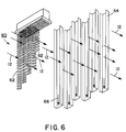
- FIG. 7 illustrates a photon generating chamber 22 used in the invention.
- the photon generating chamber 22 comprises chemical mixing nozzle 78 disposed in a cavity 80 within the photon generating chamber 22 and a chemical reactant supply manifold 81 .
- the nozzle 78 comprises a plurality of blades 82 arranged in a uniformly spaced, parallel relationship and flow shrouds 84 surrounding the blades to confine the flow gas. Adjacent pairs of the blades 82 define nozzle passages 88 extending through the nozzle 78 .
- the nozzle passages 88 include an inlet end 90 , an outlet end 92 and an intermediate throat portion 94 .
- the nozzle 78 includes at least 75 blades 84 .
- a plurality of holes 96 are formed through the blade wall 98 at opposed sides of the blade 82 .
- at least several hundred total holes 96 are formed in each blade 82 .
- the photon generating chamber 22 further includes opposed end walls 100 and opposed open ends 102 .
- the photon generating chamber 22 is approximately trapezoidal in shape, having a narrower width at the outlet end of the nozzle passages 88 than at the opening end 102 through which reaction products 27 exit into the pressure recovery system 28 .
- the end walls 100 define opposed aligned openings 106 .
- An optical axis OA extends through the opening ends 102 approximately perpendicular to the direction of flow R of the chemical reactant flow stream.
- the injection of reactant iodine 20 into the photon generating chamber 22 is preferably accomplished at supersonic velocities to expand the distance downstream of the nozzles 78 over which iodine 20 dissociation occurs. This extends the optical mode and reduces the flux level on optical components.
- the uniform flow of singlet-delta oxygen 12 to the chemical reactant mixing nozzles 78 is critical.
- such uniform distribution of the singlet-delta oxygen 12 was not a significant problem because the singlet-delta oxygen discharge port 40 on the singlet-delta oxygen generator 14 could be aligned in perfect linear fashion with the flow of reactants through the photon generating chamber 22 .
- such linear alignment between the singlet-delta oxygen outlet port 40 and the flow of reactants through the photon generating chamber 22 has been found to be impractical for space and length limitations.
- an angle of between about 60 and about 120° between the flow of singlet-delta oxygen 12 produced in the singlet-delta oxygen generator 14 and the flow of reactants through the photon generating chamber 22 is required.
- the angle is about 90°.
- the angle of about 90° should be in a downward direction, so that flow through the photon generating chamber 22 is generally vertically in a downward direction.
- a hollow connector 110 is required which maintains the laminar nature of the singlet-delta oxygen flow from the singlet-delta oxygen generator 14 .
- a cylindrical isolation valve 112 directs the flow of singlet-delta oxygen 12 around a 90° bend.
- the valve 112 is installed in a hollow connector 114 which further comprises a plurality of curved internal flow baffles 116 .
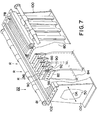
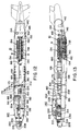
- the COIL process useable in the chemical laser of the invention operates at substantially reduced pressures. Accordingly, reaction products 27 from the photon generating chamber 22 must be drawn out of the chamber 22 and exhausted to the exterior of the airborne platform at ambient pressures. Under typical operating conditions, the pressure differential between the photon generating chamber 22 and ambient pressure can be greater than 0.2 atmospheres, and often greater than 0.3 atmospheres.
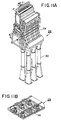
- a pressure recovery system 28 is employed, such as shown in Figures 9-11B and described in greater detail in U.S. Patent Application Serial No. (entitled “High Performance Ejector and Pressure Recovery Method,” filed concurrently herewith and incorporated herein in its entirety by this reference).
- the pressure recovery system 28 comprises a plurality of single-stage ejectors 30 .
- each photon generating module 22 comprises six single stage ejectors 30 operating in parallel.
- a preferred ejector 30 is composed substantially of a carbon-carbon fiber material to minimize weight requirements.
- an antioxidant coating can be used.
- the primary gas 120 useable in each ejector 30 is a supersonic flow generated from the reaction of decomposed hydrogen peroxide and a hydrocarbon fuel, such as an aircraft or a jet fuel, such as JP-8.
- the decomposed hydrogen peroxide is hydrogen peroxide generally of 70%-95% purity (by weight), which is catalytically decomposed to water and oxygen at elevated temperatures and pressures.
- a silver-based screen mesh catalyst can be used for this purpose.
- the decomposed hydrogen peroxide begins with a hydrogen peroxide of about 85% purity (by weight) or greater, its reaction with an aircraft or jet fuel, such as JP-8, is auto-igniting, thereby eliminating the necessity of ignition equipment.
- the supersonic flow of the primary gas 120 is generated in a primary gas generator 116 disposed within the plenum 29 .
- the primary gas 120 is then directed towards the throat section 128 of each ejector 30 .
- the primary gas generators 116 can be cooled by a coolant flowing through an external jacket (not shown).
- the preferred coolant is the hydrocarbon fuel.
- reaction products 27 from the photon generating chamber 22 are mixed with the primary gas 120 .
- the combined flow of gases 126 is then transmitted supersonically into the throat 128 of the ejector 30 .
- flow within the ejector 30 gradually becomes subsonic. Such subsonic flow is then expelled from the airborne platform via exhaust fairings 133 disposed at the bottom of the airborne platform.
- each of the photon generating modules produces a high-energy photon beam 26 is well-known in chemical lasers, such photon beam is focused transverse to the flow of chemical reactants within the photon generating chamber 22 in the invention, each of the photon beams 26 from each of the photon generating chambers 22 (from each of the photon generating modules 8 ) is optically connected laterally to form a single ultrahigh energy laser beam 26 .
- Suitable optical equipment generally known in the art is used for this purpose.
- the laser beam is constructed from multiple banks 134 of individual photon generating modules 8
- the laser beam 26 from the upstream bank 134 is inverted prior to its being combined with the laser beam produced in the downstream bank 134 .
- the photon energy produced in each photon generating module 8 tends to be of higher intensity near the top of the chamber 22 than at the lower portion of the chamber 22 .
- the reaction rate between the photon generating reactants within the photon generating chamber 22 is greater at the inlet to the chamber 22 than at the outlet.
- the photon beam 26 exiting each such photon generating module 8 is higher in intensity at its upper portion than at its lower portion.
- the laser beam 26 produced in the upstream bank 134 be inverted (so that its high energy component is at the lower portion of the beam) prior to its combination with the laser beam 26 from the downstream bank 134 .
- Inversion of the laser beam 26 is carried out by standard optical techniques known in the art.
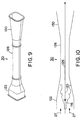
- Figures 12 and 13 show a typical combination of the chemical laser 10 of the invention mounted in an airplane 140 .
- the invention shown in Figures 12 and 13 comprises two banks 134 of photon generating modules 8 , each bank 134 containing seven modules 8.
- a main deck entry door 142 At the rearmost portion of the airplane 140 is shown a main deck entry door 142 and internal tanks for hydrogen peroxide 144 and for JP-8 146 , respectively.
- An aft optical bench 148 is shown immediately to the rear of the photon generating modules 8 .
- a catwalk 150 is disposed between the two banks 134 , with a stairway 152 granting access to the catwalk 150 .
- an access hatch 154 for access to the lower portion of the plane 140 , an aft compartment door 156 and a side cargo door 158 .
- the exhaust fairing 133 is also shown immediately below the photon generating modules 8 .
- a chlorine vaporizer 160 Below the two banks of photon generating modules 8 is shown a chlorine vaporizer 160 , an inlet scoop 162 and a chlorine tank 164 .
- a mid-optical bench 166 Immediately forward of the photon generating modules 8 is shown a mid-optical bench 166 , helium tanks 168 , hydrogen peroxide tanks 169 and ammonia tanks 170 .
- Forward of the helium and ammonia tanks 168 and 170 is a main deck entry door 172 , personnel storage lockers 174 , galley 175 , equipment storage locker 176 , bunks 178 and interlock 180 .
- baffle management E/E racks 182 and laser device E/E racks 184 are also shown forward of the helium and ammonia tanks 168 and 170 .
- a safe 186 Also shown is a safe 186 , battle management crew stations 188 , baffle management system equipment racks 190 , seats 192 , seat tracks 194 , and isolation curtain 196 , lavatory 197 , forward stairs 198 , crew entry door 200 and a main deck entry door 202 .
- a laser beam tube 204 runs from the mid-optical bench 166 through the forward end of the plane 140 to the nose of the plane 206 .
- a beam director turret assembly 208 In the nose of the plane 206 is a beam director turret assembly 208 .
- a material window 210 is located between the laser beam 204 and the beam director turret assembly 208 .
- a forward optical bench 212 Between the laser beam 204 and the beam director turret assembly 208 is a forward optical bench 212 .
- a target ranger/typer 228 Disposed at the forward end of the aircraft 140 and on the top of the aircraft 140 is a target ranger/typer 228 . Immediately behind the beam director turret assembly 208 is a forward material window 230 .
- the chemical laser 10 of the invention can also be installed in a land-based transportation device 232 , such as a truck, trailer, railroad car or similar device.
- a land-based transportation device 232 such as a truck, trailer, railroad car or similar device.
Landscapes
- Physics & Mathematics (AREA)
- Engineering & Computer Science (AREA)
- Electromagnetism (AREA)
- Optics & Photonics (AREA)
- Plasma & Fusion (AREA)
- Radar, Positioning & Navigation (AREA)
- Remote Sensing (AREA)
- General Engineering & Computer Science (AREA)
- Aviation & Aerospace Engineering (AREA)
- Lasers (AREA)
Applications Claiming Priority (2)
| Application Number | Priority Date | Filing Date | Title |
|---|---|---|---|
| US89071497A | 1997-07-09 | 1997-07-09 | |
| US890714 | 1997-07-09 |
Publications (2)
| Publication Number | Publication Date |
|---|---|
| EP0891025A2 true EP0891025A2 (de) | 1999-01-13 |
| EP0891025A3 EP0891025A3 (de) | 2000-02-23 |
Family
ID=25397044
Family Applications (1)
| Application Number | Title | Priority Date | Filing Date |
|---|---|---|---|
| EP98111900A Withdrawn EP0891025A3 (de) | 1997-07-09 | 1998-06-26 | In einem Flugzeug eingebauter chemischer Hochenergie Laser auf Jod- und Sauerstoff-Basis (COIL) |
Country Status (4)
| Country | Link |
|---|---|
| US (1) | US5974072A (de) |
| EP (1) | EP0891025A3 (de) |
| KR (1) | KR19990013596A (de) |
| CA (1) | CA2241393A1 (de) |
Cited By (5)
| Publication number | Priority date | Publication date | Assignee | Title |
|---|---|---|---|---|
| US7391936B2 (en) | 2005-01-21 | 2008-06-24 | Lucent Technologies, Inc. | Microfluidic sensors and methods for making the same |
| US7435391B2 (en) | 2003-05-23 | 2008-10-14 | Lucent Technologies Inc. | Light-mediated micro-chemical reactors |
| RU2384473C2 (ru) * | 2008-05-04 | 2010-03-20 | Николай Борисович Болотин | Гиперзвуковой самолет с боевым лазером авиационного базирования |
| RU2384474C2 (ru) * | 2008-05-06 | 2010-03-20 | Николай Борисович Болотин | Боевой самолет |
| US7780813B2 (en) | 2005-06-09 | 2010-08-24 | Alcatel-Lucent Usa Inc. | Electric field mediated chemical reactors |
Families Citing this family (26)
| Publication number | Priority date | Publication date | Assignee | Title |
|---|---|---|---|---|
| US6072820A (en) * | 1998-04-16 | 2000-06-06 | The Boeing Company | Chemical oxygen iodine laser gain generator system |
| US6154478A (en) * | 1998-06-30 | 2000-11-28 | The Boeing Company | Chemical oxygen-iodine laser (coil)/cryosorption vacuum pump system |
| US6534705B2 (en) | 2000-10-23 | 2003-03-18 | Power Beaming Corporation | Methods and apparatus for beaming power |
| US6687279B2 (en) * | 2000-12-06 | 2004-02-03 | The Boeing Company | Integrated dual source recycling system for chemical oxygen-iodine laser weapon systems |
| US6714579B2 (en) * | 2000-12-06 | 2004-03-30 | The Boeing Company | Basic hydrogen peroxide recycling system for chemical oxygen-iodine lasers |
| US7116696B2 (en) * | 2002-06-10 | 2006-10-03 | Ksy Corporation | Efficient method and apparatus for generating singlet delta oxygen at an elevated pressure |
| US7397836B2 (en) * | 2002-06-10 | 2008-07-08 | Ksy Corporation | Efficient method and apparatus for generating singlet delta oxygen at an elevated pressure |
| US7039088B2 (en) * | 2002-07-10 | 2006-05-02 | Applied Research Associates | Enhancement of chemical lasers via control of the ambient radiation environment |
| US7093541B2 (en) * | 2002-07-10 | 2006-08-22 | Applied Research Associates, Inc. | Enhancement of solid explosive munitions using reflective casings |
| US7088759B2 (en) | 2003-03-24 | 2006-08-08 | The Boeing Company | Resonator box to laser cavity interface for chemical laser |
| KR100499638B1 (ko) * | 2003-04-17 | 2005-07-05 | 주식회사 하이닉스반도체 | 칼럼 리페어 회로 |
| US7943914B2 (en) * | 2003-05-30 | 2011-05-17 | Bae Systems Information And Electronic Systems Integration, Inc. | Back illumination method for counter measuring IR guided missiles |
| US7406829B2 (en) * | 2004-06-18 | 2008-08-05 | General Electric Company | Cryogenic liquid oxidizer cooled high energy system |
| US7154931B2 (en) * | 2004-06-22 | 2006-12-26 | Ksy Corporation | Laser with Brayton cycle outlet pump |
| US7242706B2 (en) * | 2004-10-20 | 2007-07-10 | The Boeing Company | Membrane singlet delta oxygen generator and process |
| US7866638B2 (en) | 2005-02-14 | 2011-01-11 | Neumann Systems Group, Inc. | Gas liquid contactor and effluent cleaning system and method |
| US7379487B2 (en) | 2005-02-14 | 2008-05-27 | Neumann Information Systems, Inc. | Two phase reactor |
| US8864876B2 (en) * | 2005-02-14 | 2014-10-21 | Neumann Systems Group, Inc. | Indirect and direct method of sequestering contaminates |
| US8398059B2 (en) * | 2005-02-14 | 2013-03-19 | Neumann Systems Group, Inc. | Gas liquid contactor and method thereof |
| US8113491B2 (en) | 2005-02-14 | 2012-02-14 | Neumann Systems Group, Inc. | Gas-liquid contactor apparatus and nozzle plate |
| EP2167988A4 (de) * | 2007-06-14 | 2012-01-25 | Raytheon Co | Verfahren und vorrichtung zum abfangen eines projektils |
| US7815150B2 (en) * | 2007-08-20 | 2010-10-19 | The Boeing Company | Beam director flow control |
| US9863725B1 (en) | 2012-02-29 | 2018-01-09 | The United States Of America As Represented By The Secretary Of The Air Force | Systems and methods for thermal management through use of ammonium carbamate |
| WO2016118244A1 (en) * | 2015-01-21 | 2016-07-28 | Sikorsky Aircraft Corporation | Cooling system for rotorcraft laser system |
| RU2609186C2 (ru) * | 2015-03-23 | 2017-01-30 | Общество с ограниченной ответственностью "Научно-производственное предприятие"АДВЕНТ" | Газодинамический тракт сверхзвукового химического лазера с активным диффузором |
| CN111504129B (zh) * | 2020-04-10 | 2022-10-21 | 中国航天空气动力技术研究院 | 一种机载激光器气动引射结构及方法 |
Family Cites Families (13)
| Publication number | Priority date | Publication date | Assignee | Title |
|---|---|---|---|---|
| US3863176A (en) * | 1973-08-13 | 1975-01-28 | Trw Inc | Portable chemical laser |
| US4466100A (en) * | 1982-05-26 | 1984-08-14 | The United States Of America As Represented By The Secretary Of The Air Force | Delta wing nozzle assembly for chemical lasers |
| US4558451A (en) * | 1982-07-19 | 1985-12-10 | The United States Of America As Represented By The Secretary Of The Air Force | Tubular singlet delta oxygen generator |
| US4653062A (en) * | 1985-06-18 | 1987-03-24 | The United States Of America As Represented By The Secretary Of The Air Force | Chemical oxygen-iodine laser |
| US4668498A (en) * | 1985-09-27 | 1987-05-26 | Davis James A | Supersonic singlet delta oxygen aerosol generator |
| US4643889A (en) * | 1986-03-31 | 1987-02-17 | Mitsui Grinding Wheel Co., Ltd. | System for generation of singlet-delta oxygen |
| US4780880A (en) * | 1987-05-14 | 1988-10-25 | Rockwell International Corporation | Chemical oxygen iodine laser |
| CS276690B6 (en) * | 1990-08-13 | 1992-07-15 | Fyzikalni Ustav Csav | Process and apparatus for modulating the excitation of a continuous, particularly oxygen-iodine laser |
| US5198607A (en) * | 1992-02-18 | 1993-03-30 | Trw Inc. | Laser anti-missle defense system |
| US5516502A (en) * | 1992-12-10 | 1996-05-14 | Rockwell International Corporation | Singlet delta oxygen generator |
| US5417928A (en) * | 1994-02-25 | 1995-05-23 | Rockwell International Corporation | Singlet delta oxygen generator and process |
| US5883916A (en) * | 1997-07-09 | 1999-03-16 | Trw Inc. | Integrated valve and flow control apparatus and method for chemical laser system |
| US5870422A (en) * | 1997-07-09 | 1999-02-09 | Trw Inc. | Gain generator for high-energy chemical lasers |
-
1998
- 1998-01-20 US US09/009,617 patent/US5974072A/en not_active Expired - Fee Related
- 1998-06-23 CA CA002241393A patent/CA2241393A1/en not_active Abandoned
- 1998-06-26 EP EP98111900A patent/EP0891025A3/de not_active Withdrawn
- 1998-07-03 KR KR1019980026824A patent/KR19990013596A/ko not_active Ceased
Non-Patent Citations (4)
| Title |
|---|
| FUJII H ET AL: "Development of chemical oxygen-iodine laser for industrial application" SPIE VOL. 1397 - PROCEEDINGS OF 8TH INTERNATIONAL SYMPOSIUM ON GAS FLOW AND CHEMICAL LASERS, vol. 1397, 1990, pages 213-220, XP000603584 * |
| LAMBERSON S: "The airborne laser" SPIE VOL. 2702 - GAS AND CHEMICAL LASERS, SAN JOSE, CA, USA, 31 JAN.-1 FEB. 1996, vol. 2702, pages 208-213, XP000862874 ISSN: 0277-786X * |
| TEAM ABL: "TRW Approved to Begin Manufacturing First Laser Hardware" TEAM ABL NEWS RELEASE, [Online] 10 March 1997 (1997-03-10), XP002124459 Retrieved from the Internet: <URL:http://www.boeing.com/special/abl/new s/1997/031097.html> [retrieved on 1999-11-30] * |
| YELDEN E F ET AL: "Phase locking in a multichannel radial array CO/sub 2/ laser" APPLIED PHYSICS LETTERS, 22 MARCH 1993, USA, vol. 62, no. 12, pages 1311-1313, XP000354529 ISSN: 0003-6951 * |
Cited By (5)
| Publication number | Priority date | Publication date | Assignee | Title |
|---|---|---|---|---|
| US7435391B2 (en) | 2003-05-23 | 2008-10-14 | Lucent Technologies Inc. | Light-mediated micro-chemical reactors |
| US7391936B2 (en) | 2005-01-21 | 2008-06-24 | Lucent Technologies, Inc. | Microfluidic sensors and methods for making the same |
| US7780813B2 (en) | 2005-06-09 | 2010-08-24 | Alcatel-Lucent Usa Inc. | Electric field mediated chemical reactors |
| RU2384473C2 (ru) * | 2008-05-04 | 2010-03-20 | Николай Борисович Болотин | Гиперзвуковой самолет с боевым лазером авиационного базирования |
| RU2384474C2 (ru) * | 2008-05-06 | 2010-03-20 | Николай Борисович Болотин | Боевой самолет |
Also Published As
| Publication number | Publication date |
|---|---|
| KR19990013596A (ko) | 1999-02-25 |
| CA2241393A1 (en) | 1999-01-09 |
| EP0891025A3 (de) | 2000-02-23 |
| US5974072A (en) | 1999-10-26 |
Similar Documents
| Publication | Publication Date | Title |
|---|---|---|
| US5974072A (en) | High energy airborne coil laser | |
| AU2021258096B2 (en) | Directed energy deposition to facilitate high speed applications | |
| US4653062A (en) | Chemical oxygen-iodine laser | |
| US3847298A (en) | Fuel tank inerting system | |
| Perram et al. | High-energy laser weapons: technology overview | |
| US6072820A (en) | Chemical oxygen iodine laser gain generator system | |
| US7926276B1 (en) | Closed cycle Brayton propulsion system with direct heat transfer | |
| US3899749A (en) | Gas dynamic lasers | |
| US6785315B1 (en) | Mobile tactical high energy laser weapon system and method for generating a high energy laser beam | |
| US20090185592A1 (en) | Laser diode system with reduced coolant consumption | |
| US6650681B1 (en) | Sealed exhaust chemical oxygen-iodine laser system | |
| JPH11118396A (ja) | 高エネルギーの機載型化学的酸素沃素レーザ | |
| Blayvas et al. | Power optimization of small-scale chemical oxygen-iodine laser with jet-type singlet oxygen generator | |
| Wilson | Deuterium fluoride CW chemical lasers | |
| US9862498B2 (en) | Laser-charged high-speed propulsion system and method for production of high-powered laser | |
| Boreysho | High-power mobile chemical lasers | |
| EP0891023B1 (de) | Hochleistungsejektor und Verfahren zur Wiederherstellung des Drucks | |
| Zagidullin et al. | Sub-and supersonic COILs driven by a jet-type singlet oxygen generator | |
| US20180106219A1 (en) | Propulsion system | |
| Wilson | Deuterium fluoride CW chemical lasers | |
| JP2021115535A (ja) | 分解処理装置及びこれに用いられる冷却装置 | |
| US20020002821A1 (en) | Photonic engine | |
| Wilson et al. | Deuterium fluoride laser technology and demonstrators | |
| CN114348218A (zh) | 自隐气泡帷幕防护系统和潜航器 | |
| Avdeev et al. | Supersonic Gas and Chemical Lasers: Technology Development |
Legal Events
| Date | Code | Title | Description |
|---|---|---|---|
| PUAI | Public reference made under article 153(3) epc to a published international application that has entered the european phase |
Free format text: ORIGINAL CODE: 0009012 |
|
| AK | Designated contracting states |
Kind code of ref document: A2 Designated state(s): DE FR GB |
|
| AX | Request for extension of the european patent |
Free format text: AL;LT;LV;MK;RO;SI |
|
| PUAL | Search report despatched |
Free format text: ORIGINAL CODE: 0009013 |
|
| AK | Designated contracting states |
Kind code of ref document: A3 Designated state(s): AT BE CH CY DE DK ES FI FR GB GR IE IT LI LU MC NL PT SE |
|
| AX | Request for extension of the european patent |
Free format text: AL;LT;LV;MK;RO;SI |
|
| 17P | Request for examination filed |
Effective date: 20000331 |
|
| AKX | Designation fees paid |
Free format text: DE FR GB |
|
| 17Q | First examination report despatched |
Effective date: 20030331 |
|
| RAP1 | Party data changed (applicant data changed or rights of an application transferred) |
Owner name: NORTHROP GRUMMAN CORPORATION |
|
| RAP1 | Party data changed (applicant data changed or rights of an application transferred) |
Owner name: NORTHROP GRUMMAN CORPORATION |
|
| GRAP | Despatch of communication of intention to grant a patent |
Free format text: ORIGINAL CODE: EPIDOSNIGR1 |
|
| STAA | Information on the status of an ep patent application or granted ep patent |
Free format text: STATUS: THE APPLICATION HAS BEEN WITHDRAWN |
|
| 18W | Application withdrawn |
Effective date: 20040326 |