EP0891023A2 - Ejecteur à haute performance et methode de retablissement de la pression - Google Patents
Ejecteur à haute performance et methode de retablissement de la pression Download PDFInfo
- Publication number
- EP0891023A2 EP0891023A2 EP98112744A EP98112744A EP0891023A2 EP 0891023 A2 EP0891023 A2 EP 0891023A2 EP 98112744 A EP98112744 A EP 98112744A EP 98112744 A EP98112744 A EP 98112744A EP 0891023 A2 EP0891023 A2 EP 0891023A2
- Authority
- EP
- European Patent Office
- Prior art keywords
- ejector
- section
- hydrogen peroxide
- carbon
- decomposed
- Prior art date
- Legal status (The legal status is an assumption and is not a legal conclusion. Google has not performed a legal analysis and makes no representation as to the accuracy of the status listed.)
- Granted
Links
- 238000000034 method Methods 0.000 title claims description 7
- 238000011084 recovery Methods 0.000 title description 6
- MHAJPDPJQMAIIY-UHFFFAOYSA-N Hydrogen peroxide Chemical compound OO MHAJPDPJQMAIIY-UHFFFAOYSA-N 0.000 claims abstract description 54
- 239000007789 gas Substances 0.000 claims abstract description 40
- 239000000446 fuel Substances 0.000 claims abstract description 16
- 229920000049 Carbon (fiber) Polymers 0.000 claims abstract description 13
- 239000004215 Carbon black (E152) Substances 0.000 claims abstract description 13
- CREMABGTGYGIQB-UHFFFAOYSA-N carbon carbon Chemical compound C.C CREMABGTGYGIQB-UHFFFAOYSA-N 0.000 claims abstract description 13
- 239000011203 carbon fibre reinforced carbon Substances 0.000 claims abstract description 13
- 229930195733 hydrocarbon Natural products 0.000 claims abstract description 13
- 150000002430 hydrocarbons Chemical class 0.000 claims abstract description 13
- 239000007795 chemical reaction product Substances 0.000 claims abstract description 12
- 239000002131 composite material Substances 0.000 claims abstract description 11
- 239000000126 substance Substances 0.000 claims description 20
- 239000000463 material Substances 0.000 claims description 6
- 239000000203 mixture Substances 0.000 claims description 6
- 239000002826 coolant Substances 0.000 claims description 5
- 239000003963 antioxidant agent Substances 0.000 claims description 4
- 230000003078 antioxidant effect Effects 0.000 claims description 4
- 235000006708 antioxidants Nutrition 0.000 claims description 4
- BQCADISMDOOEFD-UHFFFAOYSA-N Silver Chemical compound [Ag] BQCADISMDOOEFD-UHFFFAOYSA-N 0.000 claims description 2
- 239000003054 catalyst Substances 0.000 claims description 2
- 239000004332 silver Substances 0.000 claims description 2
- 229910052709 silver Inorganic materials 0.000 claims description 2
- 239000002210 silicon-based material Substances 0.000 claims 1
- 238000006243 chemical reaction Methods 0.000 description 8
- QVGXLLKOCUKJST-UHFFFAOYSA-N atomic oxygen Chemical compound [O] QVGXLLKOCUKJST-UHFFFAOYSA-N 0.000 description 5
- 239000001301 oxygen Substances 0.000 description 4
- 229910052760 oxygen Inorganic materials 0.000 description 4
- CURLTUGMZLYLDI-UHFFFAOYSA-N Carbon dioxide Chemical compound O=C=O CURLTUGMZLYLDI-UHFFFAOYSA-N 0.000 description 2
- XLYOFNOQVPJJNP-UHFFFAOYSA-N water Substances O XLYOFNOQVPJJNP-UHFFFAOYSA-N 0.000 description 2
- ZCYVEMRRCGMTRW-UHFFFAOYSA-N 7553-56-2 Chemical compound [I] ZCYVEMRRCGMTRW-UHFFFAOYSA-N 0.000 description 1
- MYMOFIZGZYHOMD-UHFFFAOYSA-N Dioxygen Chemical compound O=O MYMOFIZGZYHOMD-UHFFFAOYSA-N 0.000 description 1
- XUIMIQQOPSSXEZ-UHFFFAOYSA-N Silicon Chemical compound [Si] XUIMIQQOPSSXEZ-UHFFFAOYSA-N 0.000 description 1
- RTAQQCXQSZGOHL-UHFFFAOYSA-N Titanium Chemical compound [Ti] RTAQQCXQSZGOHL-UHFFFAOYSA-N 0.000 description 1
- PRXLCSIMRQFQMX-UHFFFAOYSA-N [O].[I] Chemical compound [O].[I] PRXLCSIMRQFQMX-UHFFFAOYSA-N 0.000 description 1
- 230000006978 adaptation Effects 0.000 description 1
- XAGFODPZIPBFFR-UHFFFAOYSA-N aluminium Chemical compound [Al] XAGFODPZIPBFFR-UHFFFAOYSA-N 0.000 description 1
- 229910052782 aluminium Inorganic materials 0.000 description 1
- 229910002092 carbon dioxide Inorganic materials 0.000 description 1
- 239000001569 carbon dioxide Substances 0.000 description 1
- 230000015556 catabolic process Effects 0.000 description 1
- 238000006731 degradation reaction Methods 0.000 description 1
- 238000010586 diagram Methods 0.000 description 1
- 229910001882 dioxygen Inorganic materials 0.000 description 1
- 239000008246 gaseous mixture Substances 0.000 description 1
- 229910052740 iodine Inorganic materials 0.000 description 1
- 239000011630 iodine Substances 0.000 description 1
- VUZPPFZMUPKLLV-UHFFFAOYSA-N methane;hydrate Chemical compound C.O VUZPPFZMUPKLLV-UHFFFAOYSA-N 0.000 description 1
- 238000012986 modification Methods 0.000 description 1
- 230000004048 modification Effects 0.000 description 1
- 238000010525 oxidative degradation reaction Methods 0.000 description 1
- 239000000047 product Substances 0.000 description 1
- 239000011541 reaction mixture Substances 0.000 description 1
- 229910052710 silicon Inorganic materials 0.000 description 1
- 239000010703 silicon Substances 0.000 description 1
- 229910052719 titanium Inorganic materials 0.000 description 1
- 239000010936 titanium Substances 0.000 description 1
Images

Classifications
-
- H—ELECTRICITY
- H01—ELECTRIC ELEMENTS
- H01S—DEVICES USING THE PROCESS OF LIGHT AMPLIFICATION BY STIMULATED EMISSION OF RADIATION [LASER] TO AMPLIFY OR GENERATE LIGHT; DEVICES USING STIMULATED EMISSION OF ELECTROMAGNETIC RADIATION IN WAVE RANGES OTHER THAN OPTICAL
- H01S3/00—Lasers, i.e. devices using stimulated emission of electromagnetic radiation in the infrared, visible or ultraviolet wave range
- H01S3/09—Processes or apparatus for excitation, e.g. pumping
- H01S3/095—Processes or apparatus for excitation, e.g. pumping using chemical or thermal pumping
- H01S3/0951—Processes or apparatus for excitation, e.g. pumping using chemical or thermal pumping by increasing the pressure in the laser gas medium
- H01S3/0953—Gas dynamic lasers, i.e. with expansion of the laser gas medium to supersonic flow speeds
Definitions
- This invention relates generally to ejector systems and, in particular, to high performance pressure recovery systems capable of use with a high energy chemical laser.
- Ejectors and ejector systems are commonly used for moving a gas from an area of low pressure to an area of high pressure, such as to an area at ambient pressure.
- Ejectors and ejector systems are commonly used in certain chemical lasers which operate under vacuum conditions. Such ejector systems draw reaction products from the chemical laser reaction chamber so as to reduce the pressure within the reaction chamber to below ambient. By use of the ejector system, reaction gases are drawn from the reaction chamber and exhausted to a suitable exhaust site, such as to the atmosphere.
- the laser is only effective if it is mounted in an airplane flying high above a theater ballistic missile launch site. This is because the effectiveness of chemical lasers as anti-theater ballistic missile weapons is largely limited to the ability of the chemical laser to intercept the theater ballistic missile with its high energy laser beam during the first few seconds after launch. After that, the effectiveness of the chemical laser to destroy theater ballistic missiles is greatly reduced.
- the invention satisfies this need.
- the invention is a method for moving a secondary gas from a low pressure zone to a high pressure zone comprising the step of educting the secondary gas to the high pressure zone with an ejector which uses as a primary gas the reactive products of a hydrocarbon fuel and decomposed hydrogen peroxide.
- an ejector which uses as a primary gas the reactive products of a hydrocarbon fuel and decomposed hydrogen peroxide.
- Such ejectors have been found to be adaptable to very highly efficient, one-stage non-metallic ejectors having sufficiently reduced weight and length to be useable in a high energy airborne chemical laser system.
- the invention is also an ejector manufactured substantially from a carbon-carbon fiber composite. It has been found that such ejectors can be effectively used in high efficiency, one-stage ejector systems having very low weight and, therefore, being suitable for use in airborne chemical laser weapons systems.
- the invention is a method of moving a secondary gas from a low pressure zone to a high pressure zone comprising the step of educting the secondary gas to the high pressure zone with an ejector which uses as a primary gas the reaction products of a hydrocarbon fuel and decomposed hydrogen peroxide.
- the high pressure zone is substantially at ambient pressure.
- the decomposed hydrogen peroxide is mostly molecular oxygen and water.
- the decomposing of hydrogen peroxide can be accomplished by contacting the hydrogen peroxide at elevated temperatures (e.g., about 100°- 200°F) and elevated pressures (e.g., about 100-600 psig) with a silver-containing catalyst.
- elevated temperatures e.g., about 100°- 200°F
- elevated pressures e.g., about 100-600 psig
- the purity of the hydrogen peroxide is preferably higher than about 70% (by weight), for example, 70% - 90% or, more preferably, 80%-90%.
- the hydrocarbon fuel is typically an aviation or jet fuel, such as the hydrocarbon fuel known in the industry as JP-8.
- the reaction of the decomposed hydrogen peroxide with, for example, JP-8 is auto-igniting (without the assistance of a spark plug) at practical conditions of temperature and pressure. Use of such a reaction mixture, therefore, eliminates the need for separate ignition equipment.
- the reaction of JP-8 and decomposed 85% hydrogen peroxide is typically carried out at oxygen/fuel ratios of about 30.5 and produces reaction products having a temperature of about 2400°F.
- the reaction of the hydrocarbon fuel and the decomposed hydrogen peroxide produces a high energy stream of reaction products composed largely of carbon dioxide and water.
- the high pressure reaction product stream is passed through a set of multiple nozzles (e.g., 7 nozzles) and is thereby made supersonic before introduction into the inlet end of the ejector.
- the method has been found effective to move the secondary gas from a low pressure zone to a high pressure zone when the pressure differential between those zones is greater than about 0.2 atmospheres, even greater than about 0.3 atmospheres with only a single stage ejector.
- the ejector can be made from any suitable material having a sufficiently high strength to weight ratio. In some applications, titanium, anconal or aluminum can be used. Preferably, the ejector is made substantially from a carbon-carbon fiber composite. To minimize weight, the ejector can be greater than about 50% by weight carbon-carbon fiber composite material, preferably greater than about 80% by weight.
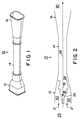
- the ejector 10 has an inlet section 12 , a throat section 14 and an outlet section 16 .
- the inlet section 12 and the outlet section 16 are both rectangular in cross-section to maximize operating pressure margins.
- the throat section 14 is generally circular or oval in cross-section.
- the inlet section 12 of the ejector 10 comprises an inlet zone 18 for the primary gas 19 and an inlet zone 20 for the secondary gas 21 .
- the inlet zone 18 for the primary gas 19 accepts high velocity primary gas 19 produced in the primary gas generator 24 and directs the primary gas 19 towards the throat section 14 .
- the primary gas 19 and the secondary gas 21 are mixed in a convergent duct or constant pressure mixing zone 26 and flow as a combined gas mixture 28 at supersonic velocities through the throat section 14 of the ejector 10 .
- the flow of gases 28 is reduced to subsonic velocity and the gases 28 are discharged via the outlet section 16 to the high pressure zone 30 .
- any carbon-carbon fiber composite materials used on the interior walls of the ejector 10 be coated with a suitable anti-oxidant material, such as a silicon-based anti-oxidant material, so as to minimize oxidative degradation of the carbon-carbon fiber composite material.
- the invention has been found to provide an extremely useful high efficiency (high pressure ratio) eduction system having a fraction of the weight commonly inherent in prior art systems. Because of the high efficiency (high pressure ratio) of the ejector system, the system can frequently use single-stage ejectors, rather than multi-stage ejectors. This is extremely important when the ejectors are used on an airborne platform, where restrictions as to length (as well as weight) are a common problem.
- Figures 3 and 4 illustrate the use of the invention in a chemical oxygen iodine laser (“COIL").
- Figure 3 illustrates a typical COIL 40 in which singlet-delta oxygen 42 is produced in a singlet-delta oxygen generator 44 and is then reacted with iodine 46 in a photon generator 48 to produce a high energy laser beam 50 .
- the photon generator 48 in a COIL 40 typically operates under reduced pressure conditions.
- Reaction products 52 produced in the photon generator 48 are exhausted to the atmosphere 54 using a pressure recovery system 56 comprising a diffuser 58 , a plenum 60 and one or more ejectors 10 .
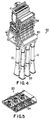
- FIGs 4 and 5 illustrate a pressure recovery system 56 using the invention in an airborne COIL 40 .
- Reaction products 52 from the photon generator 48 are drawn through the diffuser 58 by a plurality of (e. g., six) single-stage ejectors 10 of the invention disposed in parallel.
- a supersonic stream of primary gas 22 is generated in the primary gas generator 24 disposed within a plenum 60 by the reaction of a hydrocarbon fuel and decomposed hydrogen peroxide.
- the primary gas 22 is injected into the inlet section 12 of the ejectors 10 where it is mixed with the reaction products 52 from the photon generator 48 , and the combined gaseous mixture 28 is flowed through the throat section 14 .
- As the mixture 28 passes through the throat section 14 and into the outlet section 16 its velocity is slowed to subsonic, and the mixture 28 is exhausted to the atmosphere 54 through suitable exhaust fairings in the airborne platform (not shown).
- the primary gas generator 24 shown in Figure 5 is jacketed with a jacket (not shown) so as to allow the primary gas generator 24 to be cooled by a coolant flowing through the jacket.
- a coolant flowing through the jacket.
- the coolant is the hydrocarbon fuel to minimize the weight associated with the use of a separate coolant material and to allow the heat removed from the primary gas generator 24 to be efficiently used to pre-heat the hydrocarbon fuel prior to its being contacted with the decomposed hydrogen peroxide.
Landscapes
- Physics & Mathematics (AREA)
- Electromagnetism (AREA)
- Fluid Mechanics (AREA)
- Engineering & Computer Science (AREA)
- Plasma & Fusion (AREA)
- Optics & Photonics (AREA)
- Jet Pumps And Other Pumps (AREA)
- Fuel Cell (AREA)
- Separation, Recovery Or Treatment Of Waste Materials Containing Plastics (AREA)
- Lasers (AREA)
Applications Claiming Priority (2)
| Application Number | Priority Date | Filing Date | Title |
|---|---|---|---|
| US89022497A | 1997-07-09 | 1997-07-09 | |
| US890224 | 1997-07-09 |
Publications (3)
| Publication Number | Publication Date |
|---|---|
| EP0891023A2 true EP0891023A2 (fr) | 1999-01-13 |
| EP0891023A3 EP0891023A3 (fr) | 1999-01-20 |
| EP0891023B1 EP0891023B1 (fr) | 2001-01-17 |
Family
ID=25396419
Family Applications (1)
| Application Number | Title | Priority Date | Filing Date |
|---|---|---|---|
| EP19980112744 Expired - Lifetime EP0891023B1 (fr) | 1997-07-09 | 1998-07-09 | Ejecteur à haute performance et méthode de rétablissement de la pression |
Country Status (5)
| Country | Link |
|---|---|
| EP (1) | EP0891023B1 (fr) |
| JP (1) | JPH1174590A (fr) |
| KR (1) | KR19990013551A (fr) |
| CA (1) | CA2240610A1 (fr) |
| DE (1) | DE69800490T2 (fr) |
Cited By (2)
| Publication number | Priority date | Publication date | Assignee | Title |
|---|---|---|---|---|
| RU2408960C1 (ru) * | 2009-06-29 | 2011-01-10 | Общество с ограниченной ответственностью "Научно-производственное предприятие "Лазерные системы" | Газодинамический тракт непрерывного химического лазера с активным диффузором в системе восстановления давления |
| CN111211467A (zh) * | 2018-11-22 | 2020-05-29 | 中国科学院大连化学物理研究所 | 一种用于氧碘化学激光器的高效扩压装置 |
Families Citing this family (2)
| Publication number | Priority date | Publication date | Assignee | Title |
|---|---|---|---|---|
| AU2008359682B2 (en) | 2008-07-25 | 2013-08-01 | Hatch Ltd. | Apparatus for stabilization and deceleration of supersonic flow incorporating a diverging nozzle and perforated plate |
| CN103887692B (zh) * | 2012-12-21 | 2017-02-08 | 中国科学院大连化学物理研究所 | 一种平行流超音速氧碘混合喷管 |
Family Cites Families (5)
| Publication number | Priority date | Publication date | Assignee | Title |
|---|---|---|---|---|
| US3863176A (en) * | 1973-08-13 | 1975-01-28 | Trw Inc | Portable chemical laser |
| US4247833A (en) * | 1979-03-12 | 1981-01-27 | The United States Of America As Represented By The Secretary Of The Army | Minimum length diffuser for chemical lasers |
| US4235372A (en) * | 1979-07-25 | 1980-11-25 | Textron Inc. | Diffuser |
| US4487366A (en) * | 1981-03-12 | 1984-12-11 | Rockwell International Corporation | Porous-wall compact laser diffuser |
| US5735469A (en) * | 1996-05-28 | 1998-04-07 | Boeing North American, Inc. | Compact diffuser |
-
1998
- 1998-06-12 CA CA 2240610 patent/CA2240610A1/fr not_active Abandoned
- 1998-07-01 JP JP18611198A patent/JPH1174590A/ja active Pending
- 1998-07-02 KR KR1019980026679A patent/KR19990013551A/ko not_active Ceased
- 1998-07-09 DE DE1998600490 patent/DE69800490T2/de not_active Expired - Fee Related
- 1998-07-09 EP EP19980112744 patent/EP0891023B1/fr not_active Expired - Lifetime
Cited By (3)
| Publication number | Priority date | Publication date | Assignee | Title |
|---|---|---|---|---|
| RU2408960C1 (ru) * | 2009-06-29 | 2011-01-10 | Общество с ограниченной ответственностью "Научно-производственное предприятие "Лазерные системы" | Газодинамический тракт непрерывного химического лазера с активным диффузором в системе восстановления давления |
| CN111211467A (zh) * | 2018-11-22 | 2020-05-29 | 中国科学院大连化学物理研究所 | 一种用于氧碘化学激光器的高效扩压装置 |
| CN111211467B (zh) * | 2018-11-22 | 2021-07-27 | 中国科学院大连化学物理研究所 | 一种用于氧碘化学激光器的高效扩压装置 |
Also Published As
| Publication number | Publication date |
|---|---|
| DE69800490D1 (de) | 2001-02-22 |
| EP0891023B1 (fr) | 2001-01-17 |
| JPH1174590A (ja) | 1999-03-16 |
| DE69800490T2 (de) | 2001-06-07 |
| KR19990013551A (ko) | 1999-02-25 |
| CA2240610A1 (fr) | 1999-01-09 |
| EP0891023A3 (fr) | 1999-01-20 |
Similar Documents
| Publication | Publication Date | Title |
|---|---|---|
| US5974072A (en) | High energy airborne coil laser | |
| US5414992A (en) | Aircraft cooling method | |
| US4312480A (en) | Radiation shielding and gas diffusion apparatus | |
| US4644746A (en) | Gas compressor for jet engine | |
| EP0247388B1 (fr) | Système de propulsion par fusée avec possibilité d'utilisation d'air atmosphérique | |
| RU2674832C2 (ru) | Двигатель | |
| US3747339A (en) | Reaction propulsion engine and method of operation | |
| US9283530B2 (en) | Portable gas generating device | |
| EP0891023B1 (fr) | Ejecteur à haute performance et méthode de rétablissement de la pression | |
| US4133173A (en) | Ducted rockets | |
| RU2563641C2 (ru) | Гибридный ракетно-прямоточный воздушно-реактивный аэрокосмический двигатель | |
| US3899749A (en) | Gas dynamic lasers | |
| JPH06241119A (ja) | 冷却又は液化されタービンで圧縮された空気を使用するエジェクタモードと、ラムジェットモードと、超ラムジェットモードとを統合しているマルチモードエンジン | |
| US7793506B2 (en) | Emission controlled engine exhaust static test stand | |
| US5775096A (en) | Process for operating a reaction-type missile propulsion system and missile propulsion system | |
| US5836543A (en) | Discus-shaped aerodyne vehicle for extremely high velocities | |
| WO2001007773A1 (fr) | Systeme de propulsion a base de peroxyde d'hydrogene | |
| US6644016B2 (en) | Process and device for collecting air, and engine associated therewith | |
| US4013976A (en) | Gas dynamic lasers | |
| US4452039A (en) | Expendable infrared source and method therefor | |
| US3486338A (en) | Air breathing missile | |
| RU2013614C1 (ru) | Способ преобразования тепловой энергии в механическую в газотурбинном двигателе и газотурбинный двигатель для его осуществления | |
| US3886478A (en) | Multi-component flow injector pump for a flowing gas laser with low output pressure | |
| RU2176120C1 (ru) | Газодинамический лазер | |
| GB2100798A (en) | Radiation shielding and gas diffusion apparatus |
Legal Events
| Date | Code | Title | Description |
|---|---|---|---|
| PUAI | Public reference made under article 153(3) epc to a published international application that has entered the european phase |
Free format text: ORIGINAL CODE: 0009012 |
|
| PUAL | Search report despatched |
Free format text: ORIGINAL CODE: 0009013 |
|
| AK | Designated contracting states |
Kind code of ref document: A2 Designated state(s): DE FR GB |
|
| AX | Request for extension of the european patent |
Free format text: AL;LT;LV;MK;RO;SI |
|
| AK | Designated contracting states |
Kind code of ref document: A3 Designated state(s): AT BE CH CY DE DK ES FI FR GB GR IE IT LI LU MC NL PT SE |
|
| AX | Request for extension of the european patent |
Free format text: AL;LT;LV;MK;RO;SI |
|
| 17P | Request for examination filed |
Effective date: 19990209 |
|
| AKX | Designation fees paid |
Free format text: DE FR GB |
|
| GRAG | Despatch of communication of intention to grant |
Free format text: ORIGINAL CODE: EPIDOS AGRA |
|
| 17Q | First examination report despatched |
Effective date: 20000412 |
|
| GRAG | Despatch of communication of intention to grant |
Free format text: ORIGINAL CODE: EPIDOS AGRA |
|
| GRAH | Despatch of communication of intention to grant a patent |
Free format text: ORIGINAL CODE: EPIDOS IGRA |
|
| GRAH | Despatch of communication of intention to grant a patent |
Free format text: ORIGINAL CODE: EPIDOS IGRA |
|
| GRAA | (expected) grant |
Free format text: ORIGINAL CODE: 0009210 |
|
| AK | Designated contracting states |
Kind code of ref document: B1 Designated state(s): DE FR GB |
|
| REF | Corresponds to: |
Ref document number: 69800490 Country of ref document: DE Date of ref document: 20010222 |
|
| ET | Fr: translation filed | ||
| PLBE | No opposition filed within time limit |
Free format text: ORIGINAL CODE: 0009261 |
|
| STAA | Information on the status of an ep patent application or granted ep patent |
Free format text: STATUS: NO OPPOSITION FILED WITHIN TIME LIMIT |
|
| REG | Reference to a national code |
Ref country code: GB Ref legal event code: IF02 |
|
| 26N | No opposition filed | ||
| PGFP | Annual fee paid to national office [announced via postgrant information from national office to epo] |
Ref country code: FR Payment date: 20020702 Year of fee payment: 5 |
|
| PGFP | Annual fee paid to national office [announced via postgrant information from national office to epo] |
Ref country code: DE Payment date: 20020731 Year of fee payment: 5 |
|
| PGFP | Annual fee paid to national office [announced via postgrant information from national office to epo] |
Ref country code: GB Payment date: 20030702 Year of fee payment: 6 |
|
| REG | Reference to a national code |
Ref country code: GB Ref legal event code: 732E |
|
| PG25 | Lapsed in a contracting state [announced via postgrant information from national office to epo] |
Ref country code: DE Free format text: LAPSE BECAUSE OF NON-PAYMENT OF DUE FEES Effective date: 20040203 |
|
| PG25 | Lapsed in a contracting state [announced via postgrant information from national office to epo] |
Ref country code: FR Free format text: LAPSE BECAUSE OF NON-PAYMENT OF DUE FEES Effective date: 20040331 |
|
| REG | Reference to a national code |
Ref country code: FR Ref legal event code: ST |
|
| PG25 | Lapsed in a contracting state [announced via postgrant information from national office to epo] |
Ref country code: GB Free format text: LAPSE BECAUSE OF NON-PAYMENT OF DUE FEES Effective date: 20040709 |
|
| REG | Reference to a national code |
Ref country code: FR Ref legal event code: TP Ref country code: FR Ref legal event code: CD |
|
| GBPC | Gb: european patent ceased through non-payment of renewal fee |
Effective date: 20040709 |