EP0890866A2 - Display device and electronic watch - Google Patents
Display device and electronic watch Download PDFInfo
- Publication number
- EP0890866A2 EP0890866A2 EP98304542A EP98304542A EP0890866A2 EP 0890866 A2 EP0890866 A2 EP 0890866A2 EP 98304542 A EP98304542 A EP 98304542A EP 98304542 A EP98304542 A EP 98304542A EP 0890866 A2 EP0890866 A2 EP 0890866A2
- Authority
- EP
- European Patent Office
- Prior art keywords
- light
- polarisation
- linearly polarised
- separation means
- polarised light
- Prior art date
- Legal status (The legal status is an assumption and is not a legal conclusion. Google has not performed a legal analysis and makes no representation as to the accuracy of the status listed.)
- Granted
Links
Images


Classifications
-
- G—PHYSICS
- G02—OPTICS
- G02F—OPTICAL DEVICES OR ARRANGEMENTS FOR THE CONTROL OF LIGHT BY MODIFICATION OF THE OPTICAL PROPERTIES OF THE MEDIA OF THE ELEMENTS INVOLVED THEREIN; NON-LINEAR OPTICS; FREQUENCY-CHANGING OF LIGHT; OPTICAL LOGIC ELEMENTS; OPTICAL ANALOGUE/DIGITAL CONVERTERS
- G02F1/00—Devices or arrangements for the control of the intensity, colour, phase, polarisation or direction of light arriving from an independent light source, e.g. switching, gating or modulating; Non-linear optics
- G02F1/01—Devices or arrangements for the control of the intensity, colour, phase, polarisation or direction of light arriving from an independent light source, e.g. switching, gating or modulating; Non-linear optics for the control of the intensity, phase, polarisation or colour
- G02F1/13—Devices or arrangements for the control of the intensity, colour, phase, polarisation or direction of light arriving from an independent light source, e.g. switching, gating or modulating; Non-linear optics for the control of the intensity, phase, polarisation or colour based on liquid crystals, e.g. single liquid crystal display cells
- G02F1/133—Constructional arrangements; Operation of liquid crystal cells; Circuit arrangements
- G02F1/1333—Constructional arrangements; Manufacturing methods
- G02F1/1335—Structural association of cells with optical devices, e.g. polarisers or reflectors
- G02F1/133528—Polarisers
- G02F1/133536—Reflective polarizers
-
- G—PHYSICS
- G02—OPTICS
- G02B—OPTICAL ELEMENTS, SYSTEMS OR APPARATUS
- G02B5/00—Optical elements other than lenses
- G02B5/30—Polarising elements
- G02B5/3025—Polarisers, i.e. arrangements capable of producing a definite output polarisation state from an unpolarised input state
- G02B5/3033—Polarisers, i.e. arrangements capable of producing a definite output polarisation state from an unpolarised input state in the form of a thin sheet or foil, e.g. Polaroid
-
- G—PHYSICS
- G02—OPTICS
- G02F—OPTICAL DEVICES OR ARRANGEMENTS FOR THE CONTROL OF LIGHT BY MODIFICATION OF THE OPTICAL PROPERTIES OF THE MEDIA OF THE ELEMENTS INVOLVED THEREIN; NON-LINEAR OPTICS; FREQUENCY-CHANGING OF LIGHT; OPTICAL LOGIC ELEMENTS; OPTICAL ANALOGUE/DIGITAL CONVERTERS
- G02F1/00—Devices or arrangements for the control of the intensity, colour, phase, polarisation or direction of light arriving from an independent light source, e.g. switching, gating or modulating; Non-linear optics
- G02F1/01—Devices or arrangements for the control of the intensity, colour, phase, polarisation or direction of light arriving from an independent light source, e.g. switching, gating or modulating; Non-linear optics for the control of the intensity, phase, polarisation or colour
- G02F1/13—Devices or arrangements for the control of the intensity, colour, phase, polarisation or direction of light arriving from an independent light source, e.g. switching, gating or modulating; Non-linear optics for the control of the intensity, phase, polarisation or colour based on liquid crystals, e.g. single liquid crystal display cells
- G02F1/133—Constructional arrangements; Operation of liquid crystal cells; Circuit arrangements
- G02F1/1333—Constructional arrangements; Manufacturing methods
- G02F1/1335—Structural association of cells with optical devices, e.g. polarisers or reflectors
- G02F1/133528—Polarisers
- G02F1/133545—Dielectric stack polarisers
-
- G—PHYSICS
- G02—OPTICS
- G02F—OPTICAL DEVICES OR ARRANGEMENTS FOR THE CONTROL OF LIGHT BY MODIFICATION OF THE OPTICAL PROPERTIES OF THE MEDIA OF THE ELEMENTS INVOLVED THEREIN; NON-LINEAR OPTICS; FREQUENCY-CHANGING OF LIGHT; OPTICAL LOGIC ELEMENTS; OPTICAL ANALOGUE/DIGITAL CONVERTERS
- G02F1/00—Devices or arrangements for the control of the intensity, colour, phase, polarisation or direction of light arriving from an independent light source, e.g. switching, gating or modulating; Non-linear optics
- G02F1/01—Devices or arrangements for the control of the intensity, colour, phase, polarisation or direction of light arriving from an independent light source, e.g. switching, gating or modulating; Non-linear optics for the control of the intensity, phase, polarisation or colour
- G02F1/13—Devices or arrangements for the control of the intensity, colour, phase, polarisation or direction of light arriving from an independent light source, e.g. switching, gating or modulating; Non-linear optics for the control of the intensity, phase, polarisation or colour based on liquid crystals, e.g. single liquid crystal display cells
- G02F1/133—Constructional arrangements; Operation of liquid crystal cells; Circuit arrangements
- G02F1/1333—Constructional arrangements; Manufacturing methods
- G02F1/1335—Structural association of cells with optical devices, e.g. polarisers or reflectors
- G02F1/133553—Reflecting elements
-
- G—PHYSICS
- G02—OPTICS
- G02F—OPTICAL DEVICES OR ARRANGEMENTS FOR THE CONTROL OF LIGHT BY MODIFICATION OF THE OPTICAL PROPERTIES OF THE MEDIA OF THE ELEMENTS INVOLVED THEREIN; NON-LINEAR OPTICS; FREQUENCY-CHANGING OF LIGHT; OPTICAL LOGIC ELEMENTS; OPTICAL ANALOGUE/DIGITAL CONVERTERS
- G02F1/00—Devices or arrangements for the control of the intensity, colour, phase, polarisation or direction of light arriving from an independent light source, e.g. switching, gating or modulating; Non-linear optics
- G02F1/01—Devices or arrangements for the control of the intensity, colour, phase, polarisation or direction of light arriving from an independent light source, e.g. switching, gating or modulating; Non-linear optics for the control of the intensity, phase, polarisation or colour
- G02F1/13—Devices or arrangements for the control of the intensity, colour, phase, polarisation or direction of light arriving from an independent light source, e.g. switching, gating or modulating; Non-linear optics for the control of the intensity, phase, polarisation or colour based on liquid crystals, e.g. single liquid crystal display cells
- G02F1/133—Constructional arrangements; Operation of liquid crystal cells; Circuit arrangements
- G02F1/1333—Constructional arrangements; Manufacturing methods
- G02F1/1335—Structural association of cells with optical devices, e.g. polarisers or reflectors
- G02F1/13356—Structural association of cells with optical devices, e.g. polarisers or reflectors characterised by the placement of the optical elements
- G02F1/133567—Structural association of cells with optical devices, e.g. polarisers or reflectors characterised by the placement of the optical elements on the back side
Definitions
- the present invention relates to a display device for displaying characters, numeric characters, patterns and so forth.
- the present invention relates to an electronic watch such as a wristwatch, a stopwatch and so forth for counting and displaying time.
- a display device for displaying numeric characters, characters and other information using a flat display device such as a liquid crystal display device
- a display device as shown in Fig. 29 for example, one has been conventionally known in which a pair of polarisers 102 and 103 are placed on respective sides of a liquid crystal panel 101 and, further, a reflecting plate 104 is provided on the back of one polariser 103.
- the pair of polarisers 102 and 103 are placed so that, for example, transmitted polarisation axes thereof form a right angle.
- display of information such as numeric characters or the like is effected by applying a predetermined voltage between electrodes of the liquid crystal panel 101, and a region to which the voltage is not applied is a background of white or the like.
- the region to which the voltage is applied for displaying information is represented as "ON”
- the background region to which the voltage is not applied is represented as "OFF”.
- This linearly polarised light is irregularly reflected from the surface of the reflecting plate 104 after being transmitted by the polariser 103 and then, a part of the irregular reflected light is displayed to the outside after being sequentially transmitted by the polariser 103, the liquid crystal panel 101 and the polariser 102, whereby that portion is recognised as a reflection image of the reflecting plate 104, normally, as a uniform white background.
- this conventional display device information such as numeric characters is displayed in a dark colour such as black on the reflection image, which is a normally uniform white background, from the reflecting plate 104.
- the present invention is made in consideration of the above problems in the conventional display device, and its first object is to enable both information such as numeric characters or the like and a background to be displayed in a remarkably bright and easy-to-see state, and to facilitate attracting a viewer's interest by varying the background to provide a variety of information to the viewer.
- a device having a structure such that a backlight is provided in place of a light-reflecting plate.
- one of two forms can be selected to effect display: a form for effecting display using the surface of the backlight as a light-reflecting layer, and a form for effecting display using emitted light from the backlight.
- a reflection-type display form is selected during bright daytime, while a display form using the backlight is selected during dark night-time.
- the backlight is large in shape and a power source is required, so that there is a problem in that the electronic watch becomes large in shape causing inconvenience in handling and an increase in cost.
- the present invention is made in consideration of the above problems in the conventional electronic watch, and its second object is, in addition to achievement of the first object, that is, in addition to achievement of the object to display both information such as numeric characters and the background in a remarkably bright and easy-to-see state and to enable the background to be varied, to provide an electronic watch which enables the contents of the clock display surface to be viewed even under a dark environment of night-time, which can reduce the shape and moreover, which is low in cost.
- the first object is to display both information such as numeric characters and a background in a remarkably bright and easy-to-see state, and to vary the background.
- the present inventors have made an intensive effort to achieve a similar object by contriving the number of polarisation separation means and way of arrangement thereof, and consequently, they have considered another embodiment of the present invention.
- a third object of the present invention is to display both information such as numeric characters and a background in a remarkably bright and easy-to-see state and to vary the background by increasing the number of polarisation separation means which are placed on either side of the transmitted polarisation means.
- Fig. 1 is a view showing schematically an embodiment of a display device according to the present invention.
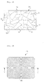
- Fig. 2 is a perspective view showing schematically an internal structure of a polarisation separation film which is used as a main part of the structure shown in Fig. 1.
- Fig. 3 is a view showing schematically the operation of the polarisation separation film shown in Fig. 2.
- Fig. 4 is a cross-sectional view showing the cross-sectional configuration of an embodiment of an electronic wristwatch which is an embodiment of an electronic watch according to the present invention.
- Fig. 5 is a plan view showing a movement used in the electronic wristwatch of Fig. 4.
- Fig. 6 is a cross-sectional view showing the cross-sectional configuration of the movement of Fig. 5.
- Fig. 7 is a plan view showing an example of display form of the electronic wristwatch of Fig. 4.
- Fig. 8 is a plan view showing an example of a light-reflecting layer.
- Fig. 9 is a cross-sectional view showing the cross-sectional configuration of another embodiment of the display device and the electronic watch according to the present invention.
- Fig. 10 is a view showing schematically an example of various display forms effected by using the electronic wristwatch of Fig. 9.
- Fig. 11 is a view showing schematically a further embodiment of the display device according to the present invention.
- Fig. 12 is a view showing schematically a still further embodiment of the display device according to the present invention.
- Fig. 13 is a perspective view showing an embodiment of a light-reflecting layer and viewing angle properties thereof.
- Fig. 14 is a perspective view showing schematically the viewing angle properties as viewed from another direction of the light-reflecting layer shown in Fig. 13.
- Fig. 15 is a plan view showing another embodiment of the light-reflecting layer.
- Fig. 16 is a plan view showing a further embodiment of the light-reflecting layer.
- Fig. 17 is a cross-sectional view showing the cross-sectional configuration taken along the line V-V of Fig. 16.
- Fig. 18 is a cross-sectional view showing a still further embodiment of the light-reflecting layer.
- Fig. 19 is a plan view showing an example of a movement used in the electronic watch according to the present invention.
- Fig. 20 is a view showing schematically a further embodiment of the display device used in the electronic watch according to the present invention.
- Fig. 21 is a view for explaining a principle of an example of a liquid crystal display device, which is a major component used in the electronic watch according to the present invention.
- Fig. 22 is a view for explaining a principle of another example of the liquid crystal display device, which is a major component used in the electronic watch according to the present invention.
- Fig. 23 is a front view showing an embodiment of the electronic watch according to the present invention.
- Fig. 24 is a cross-sectional view showing a major part of an internal structure of the electronic watch of Fig. 23.
- Fig. 25 is a perspective view showing schematically an example of a polarisation separator, which is a major component used in the electronic watch according to the present invention.
- Fig. 26 is a view showing schematically the cross-sectional configuration of an embodiment of a liquid crystal display device, which is a major component used in the electronic watch according to the present invention.
- Fig. 27 is a view showing schematically the cross-sectional configuration of another embodiment of the liquid crystal display device, which is a major component used in the electronic watch according to the present invention.
- Fig. 28 is a view showing schematically the cross-sectional configuration of a further embodiment of the liquid crystal display device, which is a major component used in the electronic watch according to the present invention.
- Fig. 29 is a view showing schematically a main part of an example of a conventional display device.
- a display device includes: (a) a first polarisation separation means which transmits linearly polarised light facing one direction and which does not transmit other linearly polarised light; (b) a transmitted polarisation axis variable means which is placed at the position receiving the linearly polarised light emitted from the first polarisation separation means, and which is capable of selecting one of the states of changing and non-changing of the polarisation axis of the transmitted polarised light; (c) a second polarisation separation means which is placed on the opposite side of the above first polarisation separation means across the transmitted polarisation axis variable means, and which transmits linearly polarised light in one direction and reflects other linearly polarised light; and (d) a light-reflecting layer which is placed on the opposite side of the above transmitted polarisation axis variable means across from the second polarisation separation means to reflect light, (e) wherein the light-reflecting layer includes a pattern on a
- an electronic watch includes: (a) a first polarisation separation means which transmits linearly polarised light facing one direction and which does not transmit other linearly polarised light; (b) a transmitted polarisation axis variable means which is placed at the position receiving the linearly polarised light emitted from the first polarisation separation means, and which is capable of selecting one of the states of changing and non-changing of the polarisation axis of the transmitted polarised light; (c) a second polarisation separation means which is placed on the opposite side of the above first polarisation separation means across the transmitted polarisation axis variable means, and which transmits linearly polarised light in one direction and reflects other linearly polarised light; and (d) a light-reflecting layer which is placed on the opposite side of the above transmitted polarisation axis variable means across from the second polarisation separation means to reflect light, (e) wherein the light-reflecting layer includes a pattern on a light
- the first polarisation separation means can be formed by a normal polariser.
- the normal polariser is a film-like member having a function of emitting linearly polarised light in one direction with respect to the incidence of natural light, and can be formed by, for example, sandwiching a polarisation layer by protective layers of TAC (cellulose triacetate).
- the above transmitted polarisation variable means can be formed by, for example, using a liquid crystal panel.
- a liquid crystal panel various types of liquid crystals, such as a TN (Twisted Nematic) liquid crystal, an STN (Super-Twisted Nematic) liquid crystal, an ECB (Electrically Controlled Birefringence) liquid crystal and so forth can be employed.
- TN Transmission Nematic
- STN Super-Twisted Nematic liquid crystal
- ECB Electrically Controlled Birefringence liquid crystal and so forth
- an STN liquid crystal using a colour compensating optical anisotropic body such as an F-STN (Film Compensated Super-Nematic) liquid crystal or the like is included.
- the above second polarisation separation means can be formed by employing (1) a polarisation separation film having a structure such that many thin films are laminated, as disclosed in an international-published patent application (International Publication No. WO95/17692 or WO95/27919), (2) a polarisation separation plate having a structure such that (1/4) ⁇ film is provided on both sides or on one side of a cholesteric liquid crystal layer, (3) a polarisation separation member (pages 427 to 429 of SID 92 DIGEST) having a structure for separating into reflected polarised light and transmitted polarised light utilising Brewster angle, or (4) a polarisation separation member utilising a hologram.
- the second polarisation separation means employed in the present invention has a function of transmitting linearly polarised light of one direction and of reflecting other linearly polarised light, in particular, of totally reflecting the linearly polarised light in the direction perpendicular to a transmitted polarisation axis.
- the second polarisation separation means constructed as described above is used in place of the normal polariser and so forth like the above feature (A), so that the light, which has been conventionally absorbed or dispersed by the polariser, can be contributed to a display by reflection, so that a background or information such as numeric characters or the like of the display device and the electronic watch can be remarkably brightly displayed.
- the second polarisation separation means is formed by a normal polariser in a conventional manner, reflected light from the light-reflecting layer is absorbed by the polariser and therefore, the reflected light of sufficient quantity cannot be provided to a viewer.
- the reflected light from the light-reflecting layer is repeatedly reflected between the second polarisation separation means and the light-reflecting layer until it matches the transmitted polarisation axis of the second polarisation separation means, and when the polarisation axis finally matches the polarisation axis of the second polarisation separation means, it passes there through to reach the viewer.
- the quantity of reflected light which has been conventionally wastefully consumed by absorption, can be efficiently provided to the viewer and consequently, the pattern provided on the light-reflecting layer can be provided to the viewer with sufficient quantity of light.
- the reflected light from the light-reflecting layer can be used for displaying information such as numeric characters or the like, or for displaying the background depending on setting of the polarisation axes of each of the components of the first polarisation separation means, the transmitted polarisation axis variable means and the second polarisation separation means.
- this reflected light from the light-reflecting layer is used for displaying the background, if a suitable pattern is formed on the light-reflecting layer, the background can be varied, whereby various information other than information such as numeric characters or the like can be provided to the viewer and moreover, the viewer's interest can be strongly attracted.
- the above pattern provided on the light-reflecting layer can be formed on the light-reflecting layer by printing, or the pattern can be formed on the light-reflecting layer by laminating a sheet material having a pattern formed thereon on the light-reflecting layer. If the pattern is directly formed on the light-reflecting layer by printing, only a small number of components are required and an assembly step of the electronic watch or the like can be simplified.
- the light-reflecting layer may include a fluorescent material.
- This fluorescent material may be a light-accumulative fluorescent material of a type capable of accumulating light. If the fluorescent material is included in the light-reflecting layer, the pattern provided on the light-reflecting layer can be recognised by the viewer as if it raises from the background, thus making strong impression on the viewer.
- the first polarisation separation means may be rotatable in relation to the transmitted polarisation axis variable means. This allows the transmitted polarisation axis of the first polarisation separation means to be changed in a desired direction as necessary, so that a display form of the electronic watch can be changed variously.
- a display form for turning off the background pattern such as a character or the like to display only information such as numeric characters or the like, and a display form for displaying simultaneously both the background pattern such as a character or the like and information such as numeric characters or the like can be freely selected as necessary.
- the first polarisation separation means is constructed so as to be rotatable in relation to the transmitted polarisation axis variable means, the following structure can be adopted to realise the action. That is, a casing for surrounding the first polarisation separation means, the transmitted polarisation axis variable means, the second polarisation separation means and the light-reflecting layer, and a rotary ring rotatably mounted to the casing are provided, and the first polarisation separation means is constructed so as to be integrally rotated with the rotary ring. If thus constructed, the viewer rotates the rotary ring from the outside of the electronic watch or the like, whereby the first polarisation separation means can be rotated in relation thereto so as to change the direction of the polarisation axis thereof.
- the light-reflecting layer may be movable in relation to the second polarisation separation means. This allows the pattern provided to the viewer to be changed variously by moving the light-reflecting layer and consequently, more varied information can be provided to the viewer and the viewer's interest can be further attracted.
- the structure for moving the light-reflecting layer is not limited to a specific structure.
- a part thereof is placed on the back of the second polarisation separation means to display it as a background, and the take-up reels are rounded to carry another part of the light-reflecting layer onto the back position, whereby the background can be changed to another pattern.
- the second polarisation separation means can be formed by various polarisation separation means, as described above.
- the second polarisation separation means is formed using a polarisation separation film having a structure disclosed in the international-published patent application (International Publication No. W095/17692 or W095/27919). This polarisation separation film has, as shown in Fig.
- a rectangular three-axis direction of XYZ when a rectangular three-axis direction of XYZ is considered, two layers of A and B are formed in a multilayer state by extrusion and further, drawn out in one direction (for example, the X direction) and not drawn out in another one direction (for example, the Y direction). That is, the X-axis direction is a drawing direction, and the Y-axis direction is a lateral direction.
- a material A has characteristics such that a refractive index is changed by drawing.
- n AX refractive index n AX
- n AY refractive index
- the thicknesses t1, t2, t3 ... ... of the respective layers A and B are varied gradually so as to reflect light (b-1), (b-2) of different wavelength from boundary surfaces of respective layers.
- light (b-1), (b-2) of different wavelength from boundary surfaces of respective layers.
- the polarisation separation film of this structure can be formed in a very thin thickness and flexibility can be imparted, so that the entire thickness of the electronic watch can be reduced and moreover, a manufacturing step thereof can be simplified.
- another display device includes: (a) a first polarisation separation means which transmits linearly polarised light facing one direction and which does not transmit other linearly polarised light; (b) a transmitted polarisation axis variable means which is placed at the position receiving the linearly polarised light emitted from the first polarisation separation means, and which is capable of selecting one of the states of changing and non-changing of the polarisation axis of the transmitted polarised light; (c) a second polarisation separation means which is placed on the opposite side of the above first polarisation separation means across the transmitted polarisation axis variable means, and which transmits linearly polarised light in one direction and reflects other linearly polarised light; and (d) a light-reflecting layer which is placed on the opposite side of the above transmitted polarisation axis variable means across from the second polarisation separation means to reflect light, (e) wherein the light-reflecting layer has characteristics such that
- another electronic watch includes: (a) a first polarisation separation means which transmits linearly polarised light facing one direction and which does not transmit other linearly polarised light; (b) a transmitted polarisation axis variable means which is placed at the position receiving the linearly polarised light emitted from the first polarisation separation means, and which is capable of selecting one of the states of changing and non-changing of the polarisation axis of the transmitted polarised light; (c) a second polarisation separation means which is placed on the opposite side of the above first polarisation separation means across the transmitted polarisation axis variable means, and which transmits linearly polarised light in one direction and reflects other linearly polarised light; and (d) a light-reflecting layer which is placed on the opposite side of the above transmitted polarisation axis variable means across from the second polarisation separation means to reflect light, (e) wherein the light-reflecting layer has characteristics such that
- the first polarisation separation means, the transmitted polarisation axis variable means and the second polarisation separation means having constructions same as those of the first polarisation separation means, the transmitted polarisation axis variable means and the second polarisation separation means described in relation to the arrangements explained in the above (1) and (2) can be used.
- the second polarisation separation means employed in the present invention has a function of transmitting linearly polarised light of one direction and of reflecting other linearly polarised light, in particular, of totally reflecting the linearly polarised light in the direction perpendicular to a transmitted polarisation axis.
- the second polarisation separation means constructed as described above is used in place of the normal polariser and so forth like the above feature (A), the light, which has been conventionally absorbed or dispersed by the polariser, can be contributed to a display by reflection, so that a background or information such as numeric characters or the like of the display device and the electronic watch can be remarkably brightly displayed.
- the second polarisation separation means is formed by a normal polariser in a conventional manner, reflected light from the light-reflecting layer is absorbed by the polariser and therefore, the reflected light of sufficient quantity cannot be provided to a viewer.
- a polarisation separation component of a type for reflecting, not absorbing linearly polarised light component other than linearly polarised light of a predetermined direction is employed for the second polarisation separation means is formed as the above component (c) of the present invention
- the reflected light from the light-reflecting layer is repeatedly reflected between the second polarisation separation means and the light-reflecting layer until it matches the transmitted polarisation axis of the second polarisation separation means, and when the polarisation axis finally matches the polarisation axis of the second polarisation separation means, it passes there through to reach the viewer.
- quantity of reflected light which has been conventionally wastefully consumed by absorption, can be efficiently provided to the viewer and consequently, the pattern provided on the light-reflecting layer can be provided to the viewer with sufficient quantity of light.
- the reflected light from the light-reflecting layer can be used for displaying information such as numeric characters or the like, or for displaying the background depending on setting of the polarisation axes of each of the components of the first polarisation separation means, the transmitted polarisation axis variable means and the second polarisation separation means.
- this reflected light from the light-reflecting layer is used for displaying the background, if the light-reflecting layer is formed by a substance having characteristics such that a visually recognised state is changed in response to a viewing angle, the background can be varied, whereby various information other than information such as numeric characters can be provided to the viewer and moreover, the viewer's interest can be strongly attracted.
- a substance having characteristics such that a visually recognised state is changed in response to a viewing angle a substance having characteristics such that a visually recognised state is changed in response to a viewing angle
- a substance having a Fresnel lens on the surface thereof, for example, a sheet material may be used.
- a mosaic pattern is formed on the surface of the hologram sheet, and hologram characteristics of respective pattern portions of the mosaic pattern can be varied intentionally.
- This allows respective pattern portions of the mosaic pattern to illuminate in a specific reflection colour following specific hologram characteristic and consequently, the hologram sheet can be illuminated in various reflection colours at respective mosaic patterns.
- reflection colours of respective mosaic pattern portions are successively changed in accordance with hologram characteristics, whereby the display form of the electronic watch or the like can be further varied.
- the second polarisation separation means can be formed by various polarisation separation components, as described above.
- the second polarisation separation means is formed using a polarisation separation film having a structure disclosed in the international-published patent application (International Publication No. WO95/17692 or WO95/27919).
- International Publication No. WO95/17692 or WO95/27919 Regarding this polarisation separation film, it is already described using Fig. 2 and Fig. 3, so that a description will be omitted.
- an electronic watch is an electronic watch for counting and displaying time which includes: (a) a first polarisation separation means which transmits linearly polarised light facing one direction and which does not transmit other linearly polarised light; (b) a transmitted polarisation axis variable means which is placed at the position receiving the linearly polarised light emitted from the first polarisation separation means, and which is capable of selecting one of the states of changing and non-changing of the polarisation axis of the transmitted polarised light; (c) a second polarisation separation means which is placed on the opposite side of the above first polarisation separation means across the transmitted polarisation axis variable means, which transmits linearly polarised light in one direction and which does not transmit other linearly polarised light; and (d) a light-reflecting means which is placed on the opposite of the above transmitted polarisation axis variable means across from the second polarisation separation means, (e) wherein the light-re
- this electronic watch is placed under a bright environment, energy is accumulated in the light-accumulative luminescent layer, and if it is placed under a dark environment such as night-time or the like, light is emitted from the light-accumulative luminescent layer, and a watch display surface is displayed brightly to the outside to be recognised by the viewer. Since the light-accumulative luminescent layer does not require a specific power source and its own thickness is thin, a small-sized electronic watch can be provided at a low cost.
- the transmitted polarisation axis variable means which is the same as that used in the display device described in the above (1) and in the electronic watch described in the above (2) can be employed.
- the first polarisation separation means may be formed by a normal polariser
- the second polarisation separation means may be formed by a reflective polarisation separation component having the following functions, that is, of transmitting linearly polarised light facing one direction and of reflecting linearly polarised light in the direction perpendicular thereto.
- This reflective polarisation component reflects linearly polarised light in the direction other than a predetermined direction, thereby to prohibit the transmission of the linearly polarised light.
- the above reflective polarisation separation component has a function of reflecting linearly polarised light in the direction other than a predetermined direction, so that a novel and special display form, which cannot realised when using the normal polariser, can be realised.
- the reflective polarisation separation component having functions as described above can be formed by employing (1) a polarisation separation film having a structure such that many thin films are laminated, as disclosed in an international-published patent application (International Publication No. W095/17692 or W095/27919), (2) a polarisation separation plate having a structure such that (1/4) ⁇ film is provided on both sides or on one side of a cholesteric liquid crystal layer, (3) a polarisation separation member (pages 427 to 429 of SID 92 DIGEST) having a structure for separating into reflected polarised light and transmitted polarised light utilising Brewster angle, or (4) a polarisation separation member utilising a hologram.
- the light-accumulative luminescent layer can hold electrons excited by absorbed light in its excited state, and may be formed by including a substance which causes light emission by recombination of the held electrons and positive holes. If such a luminescent substance absorbs light, the electrons are first excited in a first excited state and thereafter, captured from the first excited state by a capture centre composed of an impurity centre and a crystal lattice defect, and held thereby in a predetermined excited state.
- the electrons held by the capture centre return to the first excited state due to thermal activation, and combines again with positive holes to emit light.
- a luminescent substance for example, a substance having strontium aluminum oxide (SrAl 2 O 4 ) as a base crystal and further, including rare earth elements as impurities may be mentioned. According to this electronic watch, the emission time can be continued for a long time when the light-reflecting layer is employed as an illuminant.
- an electronic watch is an electronic watch for counting and displaying time which includes: (a) a transmitted polarisation axis variable means capable of changing a transmitted polarisation axis; (b) a first polarisation separation means and a second polarisation separation means placed on both sides, respectively, of the transmitted polarisation axis variable means; and (c) a third polarisation separation means placed opposite of the transmitted polarisation axis variable means with respect to the second polarisation separation means, (d) wherein the first polarisation separation means is a polarisation separation means which can emit linearly polarised light in a first direction from a second side opposing the first side with respect to light incident from a first side, and which can emit the linearly polarised light in the first direction from the first side with respect to light incident from the second side, (e) wherein the second polarisation separation means is a polarisation separation means (i) which can transmit, of the light incident from a third
- two display states of the first display state and the second display state can be obtained in accordance with a state of the transmitted polarisation axis of the transmitted polarisation axis variable means. Since a display colour of the first display state and a display colour of the second display state are different from each other, a watch display can be effected by these two colours.
- both the display states are the display states due to light reflected from the polarisation separation means, so that remarkably bright display can be obtained as compared with a display element of a conventional system such that polarised light is transmitted by two sheets of polarisers each having a structure for separating polarised light by light absorption.
- the transmitted polarisation axis variable means may include a liquid crystal display device.
- the liquid crystal display device may include a TN liquid crystal device, an STN liquid crystal device, or an ECB liquid crystal device.
- the STN liquid crystal device may include an STN liquid crystal device using colour compensating optical anisotropic body.
- the first polarisation separation means may include a polariser.
- an angle formed by the second direction and the fourth direction is 45° to 90°.
- an angle formed by said second direction and said fourth direction is 60° to 90°.
- an angle formed by said second direction and said fourth direction is 75° to 90°.
- light-diffusing means may further be provided. This allows a watch display state to be changed into a non-mirror surface state.
- a light source may be further provided.
- the second polarisation separation means may be a laminated product in which a plurality of layers are laminated by being adhered to each other, and a refractive index of the plurality of layers may be equal in a sixth direction between layers adjacent to each other, and may be different in a seventh direction perpendicular to the sixth direction.
- the third polarisation separation means may be a laminated product in which a plurality of layers are laminated by being adhered to each other, and a refractive index of the plurality of layers may be equal in an eighth direction between layers adjacent to each other, and may be different in a ninth direction perpendicular to the eighth direction.
- polarisation separator 21 of a laminate structure as shown schematically in Fig. 25 may employed as the polarisation separator 21.
- a functional principle of the polarisation separator 21 will be described below.
- the polarisation separator shown herein has a structure of a plurality of layers formed by alternately laminating two different layers A and B.
- the refractive index nAX in the X direction of layers A and the refractive index n AY in the Y direction are different from each other, i.e., n AX ⁇ n AY .
- the thickness of the layer A in the Z direction is taken as t A
- the thickness of the layer B in the Z direction is taken as t B
- the wavelength of the incident light is taken as ⁇
- t A ⁇ n AX + t B ⁇ n BX ⁇ /2 when light of wavelength ⁇ is incident on the top surface 21a of the polarisation separator 21 from the direction perpendicular to the surface, of the light, linearly polarised light in the X direction is reflected by the polarisation separator 21 as linearly polarised light in the X direction.
- linearly polarised light which is the light of wavelength ⁇ and incident on the bottom surface 21b of the polarisation separator 21 in the direction perpendicular to the surface is reflected by the polarisation separator 21 as linearly polarised light in the X direction.
- the X direction to be reflected is called a reflection axis.
- the thickness of the layer A in the Z direction and the thickness of the layer B in the Z direction can be changed to allow the above expression (1) to be held over a certain wavelength range of visible light. That is, a linearly polarised light component in the Y direction is transmitted as linearly polarised light in the Y direction, light which is a linearly polarised light component in the X direction and in a certain wavelength ( ⁇ ) is reflected as linearly polarised light in the X direction, and light, which is a linearly polarised light component in the X direction and in other wavelength region (- ⁇ ) is transmitted as linearly polarised light in the X direction.
- Fig. 4 shows the cross-sectional configuration of an embodiment of an electronic watch as claimed in claim 2 using a display device according to the present invention claimed in claim 1 as a display section.
- This electronic watch is a wristwatch which is composed of, for example, a plastic casing 1, a movement 2 stored in the casing 1, a glass plate 3 which is fixed to the casing 1 and located on the movement 2, and a rear cover 4 for fixing the movement 2.
- Numeral 6 denotes a wristband.
- the movement 2 includes, as shown in Fig. 6, a panel frame 7, a liquid crystal panel 8 as a transmitted polarisation axis variable means which is supported by the panel frame 7, a polariser 11 as a first polarisation separation means which is adhered on the outer surface (the upper surface of the drawing) of the liquid crystal panel 8, a polarisation separation film 12 as a second polarisation separation means which is placed on the opposite side of the polariser 11 across the liquid crystal panel 8, a backlight 18 disposed on the bottom surface side of the polarisation separation film 12, and a battery 9.
- the polariser 11 is formed of a normal polarisation plate, and acts so as to transmit linearly polarised light facing one direction and so as not to transmit other polarised light by absorbing and scattering and so forth. According to this embodiment, in Fig. 1, the position of the polariser 11 is set so that the polarisation axis of the polariser 11 faces the direction perpendicular to the plane of the drawing.
- the polarisation separation film 12 is composed of, as shown in Fig. 2, a polarisation separation film having a structure such that multiple thin films are laminated.
- the polarisation separation film 12 acts so as to transmit linearly polarised light facing one direction and to reflect other linearly polarised light rather than to absorb, in particular, acts so as to entirely reflect linearly polarised light in the direction perpendicular to the polarisation axis.
- the thicknesses t1, t2, t3 ... ... (see Fig. 2) of respective layers are set so that the light of all wavelengths in the visible light region can be reflected.
- the plane of the polarisation separation film 12 opposing the liquid crystal panel 8 may be a smooth plane for mirror-reflecting light, or may be a light-scattering layer, i.e., a light-diffusing layer. In the case of the smooth plane, a reflected image from the polarisation separation film 12 is a mirror reflection image.
- a reflected image from the polarisation separation film 12 has a single (normally, white) background colour with no pattern. If a colour layer is provided on the surface of the polarisation separation film 12, the image can be suitably coloured.
- the backlight 18 of Fig. 6 is composed of, for example, an EL, which is a plane light emitting element.
- the surface of the backlight 18 is, as shown in Fig. 1, a light-reflecting layer 18a for irregularly reflecting light.
- the light-reflecting layer 18a is formed by, as shown in Fig. 8, providing a pattern 20 on a white background by printing.
- a suitable mark such as a logo and a trademark, a suitable character and other various patterns may be considered as the pattern 20, the characters "ABC" shall be drawn in this embodiment.
- the liquid crystal panel 8 has a pair of transparent glass substrates 13a and 13b opposing each other, and liquid crystal, such as TN liquid crystal L, is sealed in a gap formed between the glass substrates, a so-called cell gap.
- a plurality of transparent electrodes 14 for displaying information such as numeric characters, characters or the like are formed on the glass substrates 13a and 13b, as shown in Fig. 5.
- a transparent electrode divided into seven segments is employed as a transparent electrode for displaying a one-digit numeric character.
- a predetermined voltage can be applied between a pair of segment transparent electrodes 14 opposing to each other which are formed on the pair of glass substrates 13a and 13b, respectively, and according to whether the voltage is applied (ON) or the voltage is not applied (OFF), the alignment of the liquid crystal L can be set to one of the two states.
- the liquid crystal of this embodiment is set so that the polarisation axis of the linearly polarised light passing through the liquid crystal is not changed when it is in the ON state, while the polarisation axis of the polarised light passing through the liquid crystal is twisted only 90° when it is in the OFF state.
- This wristwatch has two kinds of light source forms: a light source form utilising emission of the backlight 18, and a light source form utilising external natural light without utilising the emission of the backlight 18.
- a light source form utilising emission of the backlight 18 a light source form utilising external natural light without utilising the emission of the backlight 18.
- the liquid crystal panel 8 of that region is set to the OFF state, and when information such as numeric characters or the like is to be displayed on the display surface of the wristwatch, the liquid crystal panel 8 of that region is set to the ON state.
- the liquid crystal panel 8 is set to the OFF state in Fig. 1.
- the external light i.e., natural light
- linearly polarised light in the direction perpendicular to the plane of the drawing is transmitted by the polariser 11, and the polarisation direction is twisted 90° by the liquid crystal panel 8 in the OFF state to become linearly polarised light in the direction parallel to the plane of the drawing.
- This linearly polarised light is transmitted by the polarisation separation film 12 to reach the light-reflecting layer 18a and is reflected therefrom.
- the reflected light is transmitted by the polarisation separation film 12, the liquid crystal panel 8 and the polariser 11 to be recognised by a viewer.
- the background colour around the pattern 20 should be relatively dark colour, such as grey, in order to distinguish the information such as characters or the like.
- the colour of the ground of the light-reflecting layer 18a is coloured relatively dark in advance.
- the light irregularly reflected from the light-scattering layer 18a includes a component for shifting the polarisation axis thereof, and the optical component is reflected from the polarisation separation film 12 to return to the light-scattering layer 18a again, and repeats the reflection until it matches the polarisation axis of the polarisation separation film 12, and then comes out upward.
- the optical component by which the polarisation axis is shifted is absorbed by the polariser and does not come out upward.
- the light reflected from the light-scattering layer 18a can be efficiently guided to the outside, and hence the pattern 20 can be displayed in a remarkably bright and easy-to-see state.
- the liquid crystal panel 8 is set to the ON state. Thereupon, as shown by the arrow P, linearly polarised light in the direction perpendicular to the plane of the drawing is taken out of the external light by the polariser 11, and the linearly polarised light is transmitted by the liquid crystal panel 8.
- the liquid crystal panel 8 Since the liquid crystal panel 8 is in the ON state at this time, the polarisation direction of the linearly polarised light is maintained in the direction perpendicular to the plane of the drawing without being twisted, and therefore, the linearly polarised light is reflected between each of the layer surfaces in the polarisation separation film 12 in response to the wavelength, and the reflected light is displayed to the outside after being sequentially transmitted by the liquid crystal panel 8 and the polariser 11. This allows a portion of a segment in the transparent electrodes 14 in Fig. 7 to be displayed by the reflection colour of the polarisation separation film 12.
- the pattern 20 when display is effected using the external natural light, information such as numeric characters or the like displayed by the segment electrodes 14 can be recognised on a background of grey or the like on which the pattern 20 is drawn.
- information such as numeric characters or the like displayed by the segment electrodes 14 can be recognised on a background of grey or the like on which the pattern 20 is drawn.
- the conventional display form only information such as numeric characters or the like is displayed on a single background colour such as white, so that the display form is dull.
- the pattern 20 can be drawn on the background and varied, so that various information can be provided to the viewer and the viewer's interest can be strongly attracted.
- the backlight 18 is lit and further, the liquid crystal panel 8 is set to the OFF state.
- the linearly polarised light in the direction parallel to the plane of the drawing is taken out of the emitted light i.e., natural light of the backlight 18 by the polarisation separation film 12 and further, the polarisation direction of the linearly polarised light is twisted 90° by the liquid crystal display device 8 in the OFF state to be converted into linearly polarised light in the direction perpendicular to the plane of the drawing.
- This linearly polarised light is transmitted by the polariser 11 to be emitted to the outside, and is recognised as the background. In other words, the background having the pattern 20 displayed on the emission colour of the backlight 18 is recognised.
- the backlight 18 is lit and further, the liquid crystal panel 8 is set to the ON state.
- linearly polarised light in the direction parallel to the plane of the drawing is taken out of the emitted light of the backlight 18 by the polarisation separation film 12, and the linearly polarised light is transmitted by the liquid crystal panel 8 in the ON state. Since the polarisation axis of the linearly polarised light is in the direction parallel to the plane of the drawing, it is absorbed or scattered by the polariser 11 and prevented from being emitted to the outside, and hence this portion is recognised as black from the outside.
- the light-reflecting layer 18a of Fig. 1 may include a fluorescent material which emits fluorescence when light falls thereon. This allows the pattern 20 printed on the light-reflecting layer 18a to be clearly recognised in such a manner as to raise from the background colour emitting fluorescence, thereby making a strong impression on the viewer.
- Fig. 9 shows another embodiment of the display device as claimed in claim 1 according to the present invention and the electronic watch as claimed in claim 2 according to the present invention.
- This embodiment differs from the previous embodiment shown in Fig. 4 in that a rotary ring 10 rotatable in relation to the casing 1 is provided on the casing 1, and the glass plate 3 and the polariser 11 are integrally connected to the rotary ring 10.
- the viewer lifts up the rotary ring 10 with the fingers and rotates it about the centre axis L0 of the wristwatch, whereby the polariser 11 can be rotated about the centre axis L0.
- the polariser 11 is rotated in this way, since the polarisation axis of the polariser 11 is changed from the direction perpendicular to the plane of the drawing in Fig. 1, the transmission characteristics of the linearly polarised light due to the polariser 11 are changed, so that display contents to be displayed to the outside are changed variously and the viewer's interest can be strongly attracted.
- the transmitted polarisation axis of the polariser 11 can be changed in the direction parallel to the plane of the drawing, as shown in Fig. 10.
- the background is displayed by the reflection image of the polarisation separation film 12, as shown by the arrow Q, while information such as numeric characters or the like is displayed by the reflection colour from the light-reflecting layer 18a.
- the background is not displayed using the light-reflecting layer 18a, so that the pattern 20 is not displayed on the background, and information such as numeric characters or the like is displayed by the segment electrodes 14 on the background of a single colour with no pattern.
- the display form of the electronic watch can be freely changed between the form for displaying simultaneously both the pattern 20 and information such as numeric characters or the like, as shown in Fig. 7, and the form for displaying only information such as numeric characters or the like by turning off the pattern 20, as shown in Fig. 5.
- the background including the pattern 20 is displayed by the reflection image (the arrow Q of Fig. 1) of the light-reflecting layer 18a, and information such as numeric characters or the like due to the segment electrodes 14 is displayed by the reflection colour (the arrow P of Fig. 1) of the polarisation separation film 12.
- the background is displayed by the reflection image (the arrow Q of Fig. 10) of the polarisation separation film 12, and information such as numeric characters or the like is displayed by the reflected colour (the arrow P of Fig. 10) of the light-reflecting layer 18a.
- the pattern 20 can be turned on and turned off, and at the same time, the display colours of the background and information such as numeric characters or the like can be changed. Therefore, a very exciting display to the viewer can be provided.
- Fig. 11 shows a further embodiment of the display device as claimed in claim 1 according to the present invention and the electronic watch as claimed in claim 2 according to the present invention.
- This embodiment differs from the previous embodiment shown in Fig. 1 in that a pair of take-up reels 16a and 16b are provided on both sides of the backlight 18, and the light-reflecting layer 18a in continuous form is looped over the reels.
- the pattern 20 of "ABC" shown in Fig. 8 instead of the pattern 20 of "ABC" shown in Fig. 8, another pattern consisting of a suitable logo, a mark, a character and so forth is printed.
- the rotational drive of the reels 16a and 16b can be effected manually by the viewer from the outside, or can be effected automatically using a drive source provided in the wristwatch.
- the display device of the present invention is applied to the display section of an electronic wristwatch, the display device of the present invention can be applied to all types of electronic equipment.
- the present invention is applied to the wristwatch is shown in the above-described embodiments, it is a matter of course that the present invention can be applied to an electronic watch having another structure, such as a stopwatch and so forth.
- liquid crystal panel using TN liquid crystal is employed as the transmitted polarisation axis variable means capable of selecting one of the states of changing and non-changing of the polarisation axis of the transmitted polarised light in the above-described embodiments
- a liquid crystal panel using STN liquid crystal or ECB liquid crystal can be employed in place of this.
- a multilayer structure in which a plurality of thin films are laminated as shown in Fig. 2, is employed as the second polarisation separation means for effecting the action of transmitting linearly polarised light of one direction and of reflecting other linearly polarised light.
- a polarisation separation plate having a structure such that a (1/4) ⁇ film is provided on both sides or on one side of a cholesteric liquid crystal layer
- a polarisation separation member (pages 427 to 429 of SID 92 DIGEST) having a structure for separating into reflected polarised light and transmitted polarised light utilising Brewster angle
- a polarisation separation member utilising a hologram may be employed.
- Fig. 12 shows the cross-sectional configuration of an embodiment of the display device as claimed in claim 10 according to the present invention. If this display device is used as the display section of the electronic watch shown in Fig. 4, the electronic watch as claimed in claim 11 can be constructed. Since the structure of the electronic watch has already been described using Fig. 2, Fig. 3, Fig. 5 and Fig. 6, a description thereof will be omitted. In addition, since the components in Fig. 12 indicated by the same numerals as those of the components in Fig. 1 are the components having the same functions, a description thereof will be omitted.
- the light-reflecting plate 28 is formed by a hologram sheet.
- the colour of the reflected light from the hologram sheet is changed corresponding thereto.
- the whole of the hologram sheet 28 changes in colour continuously for the viewer in a manner of, for example, blue-red-green-red-blue.
- the whole of the hologram sheet 28 changes in colour continuously for the viewer in a manner of, for example, white-green-white.
- the liquid crystal panel 8 is set to the OFF state in Fig. 12.
- the polariser 11 linearly polarised light in the direction perpendicular to the plane of the drawing is transmitted by the polariser 11, and the polarisation direction is twisted 90° by the liquid crystal panel 8 in the OFF state to become linearly polarised light in the direction parallel to the plane of the drawing.
- the linearly polarised light is transmitted by the polarisation separation film 12 to reach the light-reflecting plate 28 and is reflected therefrom.
- the reflected light is recognised by the viewer after being transmitted by the polarisation separation film 12, the liquid crystal panel 8 and the polariser 11. Since the light-reflecting plate 28 is composed of a hologram sheet, if the viewer changes an angle for viewing the watch display from the outside, the reflection colour of the light-reflecting plate 28 is changed variously in response to the angle, as shown in Fig. 13 and Fig. 14. Therefore, the viewer will recognise the background of which the colour is variously changed in response to the angle.
- the light irregularly reflected from the light-reflecting plate 28 includes a component for shifting the polarisation axis thereof, and the light component is reflected from the polarisation separation film 12 to return to the light-reflecting plate 28 again, and is repeatedly reflected until it matches the polarisation axis of the polarisation separation film 12, and then comes out upward.
- the light component by which the polarisation axis is shifted is absorbed by the polariser and does not come out upward.
- the light reflected from the light-reflecting plate 28 can be efficiently guided to the outside, and hence the reflection image due to hologram properties of the light-reflecting plate 28 can be displayed in a remarkably bright and easy-to-see state.
- the liquid crystal panel 8 is set to the ON state. Thereupon, as shown by the arrow P, linearly polarised light in the direction perpendicular to the plane of the drawing is taken out of the external light by the polariser 11, and the linearly polarised light is transmitted by the liquid crystal panel 8.
- the liquid crystal panel 8 Since the liquid crystal panel 8 is in the ON state at this time, the polarisation direction of the linearly polarised light is maintained in the direction perpendicular to the plane of the drawing without being twisted, and therefore, the linearly polarised light is reflected between each of the layer surfaces in the polarisation separation film 12 in response to the wavelength, and the reflected light is displayed to the outside after being sequentially transmitted by the liquid crystal panel 8 and the polariser 11. This allows a portion of a segment in the ON state of the transparent electrodes 14 in Fig. 5 to be displayed by the reflection colour of the polarisation separation film 12.
- Fig. 15 shows another embodiment of the light-reflecting plate which can be used in the display device according to claim 10 and in the electronic watch according to claim 11.
- a light-reflecting plate 38 shown herein is constituted by using the hologram sheet similar to the previous light-reflecting plate 28 shown in Fig. 13 and Fig. 14. The difference between the two is as follows.
- the entire surface of the light-reflecting plate 28 of Fig. 13 has a single hologram property, and therefore, when the colour of the light-reflecting plate 28 is changed in response to the viewing angle, the whole of the light-reflecting plate 28 is uniformly changed in colour.
- each mosaic pattern portion M emits reflected light of a colour in accordance with its hologram property, so that the whole of the light-reflecting plate 38 emits light in various colours in the individual mosaic pattern portion M. Then, the emission display is used as the background of the watch display. Therefore, the viewer can enjoy the variety of display forms as compared with a case of viewing a conventional background of a single colour.
- the individual mosaic pattern portion M changes the reflection colour in accordance with its own hologram property. If this is observed over the light-reflecting plate 38, the light-reflecting plate is brilliantly continuously changed in colour in the individual mosaic pattern portion M, for example, green-red,-blue-grey. Therefore, the viewer can enjoy a further variety of display forms.
- Fig. 16 shows a further embodiment of a light-reflecting plate which can be used in the display device according to claim 10 and in the electronic watch according to claim 11.
- a light-reflecting plate 48 shown herein has a Fresnel lens 49 made of resin which is formed in a concentric pattern on the surface thereof.
- the Fresnel lens 49 is, as generally known and as shown in Fig. 17, formed by, for example, dividing a lens surface L of a convex lens for each concentric pattern, and by arranging them in the form of a flat surface.
- a light-reflecting layer 47 such as Al (aluminum) is adhered to the back of the Fresnel lens 49.
- the Fresnel lens 49 is formed to be colourless and transparent, the light incident on the light-reflecting plate 48 is incident on the light-reflecting layer 47 through the Fresnel lens 49, reflected therefrom and then guided to the outside through the Fresnel lens 49 again. Therefore, the viewer viewing the watch display of Fig. 5 recognises a mirror reflection image optically processed by the Fresnel lens 49 as the background of the information display such as numeric characters or the like using the segment electrodes 14. This background is changed to various states by changing the viewing angle of the watch display, so that a variety of displays can be provided to the viewer.
- the Fresnel lens 49 is formed by suitably coloured resin, the background can be configured by a coloured reflection image, so that a further variety of background can be viewed.
- Fig. 18 shows a still further embodiment of the light-reflecting plate, which can be used in the display device according to claim 10 and in the electronic watch according to claim 11.
- a light-reflecting plate 58 shown herein can be formed into a plane state of the concentric pattern shown in Fig. 16, for example.
- the light-reflecting plate 58 is composed of an Al reflecting layer 57 rugged for every concentric pattern, and a colour resin layer 59 covered thereon.
- the reflected image recognised from the outside is changed in various states.
- the changes can be recognised such that the concentric pattern of Fig. 16 can be partially clearly viewed and not, and that a strongly shining portion moves left and right, up and down, or in a circumferential direction.
- the background is displayed using the light-reflecting plate 58, the appearance of the background can be changed variously in response to the change in the viewing angle direction of the viewer and hence, the watch display and so forth can be varied.
- the display device as claimed in claim 10 is applicable as a display section for all types of electronic equipment except the electronic wristwatch.
- a liquid crystal panel using the TN liquid crystal is employed as the transmitted polarisation axis variable means capable of selecting one of the states of changing and non-changing the polarisation axis of transmitted polarised light in the above-described embodiments
- a liquid crystal using an STN liquid crystal or an ECB liquid crystal can be employed in place of this.
- a multilayer structure in which a plurality of thin films are laminated as shown in Fig. 2 is employed as the second polarisation separating means for effecting the action of transmitting linearly polarised light of one direction and of reflecting other linearly polarised light.
- a polarisation separation plate having a structure such that (1/4) ⁇ films are provided on both sides or one side of cholesteric liquid crystal layer
- a polarisation separation member (pages 427 to 429 of SID 92 DIGEST) having a structure for separating into reflected polarised light and transmitted polarised light utilising Brewster angle
- a polarisation separation member utilising a hologram may be employed.
- Fig. 20 schematically shows a main part of another embodiment of the electronic watch according to claim 17.
- the embodiment shown herein differs from the previous embodiments in that a reflective polarisation separation film 12 is used as the second polarisation separation means which is provided on the opposite side of the first polariser 11 across the liquid crystal panel 8.
- Other points are the same as those of the components of Fig. 1, and the same members are indicated by the same references.
- the polarisation separation film 12 which is the same as the polarisation separation film 12 used in the display device of Fig. 1 can be used in this embodiment, and more specifically, a film of a multilayer structure shown in Fig. 2 can be used.
- This polarisation separation film 12 differs from a normal polariser 15 in the following point.
- the normal polariser absorbs linearly polarised light except the linearly polarised light capable of being transmitted, while the reflective polarisation separation film 12 reflects the linearly polarised light. This fact has already been described. Since the polarisation separation film 12 has such optical characteristics, the following display states can be realised in the embodiment of Fig. 20.
- the liquid crystal panel 8 When display is effected using external natural light under a daytime bright environment, especially when the background colour is displayed, the liquid crystal panel 8 is first set to the OFF state in Fig. 20. Thereupon, as shown by the arrow P in the drawing, of the external light, i.e., natural light, linearly polarised light in the direction parallel to the plane of the drawing is transmitted by the first polariser 11, and the polarisation direction is twisted 90° by the liquid crystal panel 8 in the OFF state to become linearly polarised light in the direction perpendicular to the plane of the drawing.
- the external light i.e., natural light
- the linearly polarised light is reflected between layer surfaces in the polarisation separation film 12 in response to the wavelength, and the reflected light is displayed to the outside after being sequentially transmitted by the liquid crystal panel 8 and the first polariser 11.
- the liquid crystal panel is set to the ON state.
- linearly polarised light in the direction parallel to the plane of the drawing is taken out of the external light by the first polariser 11, and the linearly polarised light is transmitted by the liquid crystal panel 8. Since the liquid crystal panel 8 is in the ON state at this time, the polarisation direction of the linearly polarised light is maintained in the direction parallel to the plane of the drawing without being twisted and hence, the linearly polarised light is transmitted by the polarisation separation film 12 and further reflected irregularly from the surface of the light reflecting plate 68.
- a high-contrast "black” can be positively produced by providing a semi-transmissive light absorber between the polarisation separation film 12 and the light-reflecting plate 68 and by positively absorbing light by the light absorber.
- information such as numeric characters or the like can be displayed in a dark colour on the white background colour by utilising reflection characteristics of the light reflector 68. At that time, energy is accumulated in the light-accumulative luminescent layer of the light reflector 68.
- the liquid crystal panel 8 When display is effected using the emitted light of the light reflector 68 under a night-time dark environment, especially when displaying the background colour, the liquid crystal panel 8 is set to the OFF state. Thereupon, as shown by the arrow C, linearly polarised light in the direction parallel to the plane of the drawing is taken out of the emitted light, i.e., natural light of the light reflector 68 by the polarisation separation film 12, and the polarisation direction of the linearly polarised light is twisted 90° by the liquid crystal panel 8 in the OFF state to be converted into linearly polarised light in the direction perpendicular to the plane of the drawing. Since the linearly polarised light is absorbed or diffused by the first polariser 11 to be prevented from being emitted to the outside, it is recognised as the "black" background colour from the outside.
- the liquid crystal panel 8 is set to the ON state. Thereupon, as shown by the arrow D, linearly polarised light in the direction parallel to the plane of the drawing is taken out of the emitted light of the light-reflecting plate 68 by the polarisation separation film 12, and the linearly polarised light is transmitted by the liquid crystal panel 8 in the ON state, and is further transmitted by the first polariser 11 to be displayed to the outside.
- the colour of information such as numeric characters or the like displayed at this time is determined by the colour of the emitted light of the light-reflecting plate 68, if the colour of the emitted light is set to a colour such as yellow green, red, or orange-colour, which is easily identified with respect to the "black", the information such as numeric characters can be viewed in a very easy-to-identify state.
- the colour of the emitted light is set by, for example, providing a colour filter.
- the light-reflecting plate 68 acts as the illuminant, so that information such as numeric characters or the like is displayed in a colour, such as yellow green and the like, on the black background colour. This display is continued until the energy accumulated in the light-accumulative luminescent layer of the light-reflecting plate 68 is used up.
- the display surface of the watch can be displayed brightly based on the emitted light from the light-accumulative luminescent layer of the light-reflecting plate 68. Further, the light-accumulative luminescent layer does not require a specific power source and its own thickness is thin, so that the wristwatch can be formed in small size at a low cost.
- the black information display is effected on a white ground when the external natural light is employed (the arrow P and the arrow Q), while the information display by the colour of the emitted light such as yellow green is effected on a black ground when emission characteristics of the light-reflecting plate 68 are employed (the arrow C and the arrow D).
- the display form is such that only the black information display is effected on the white ground.
- the display form of this embodiment is a very novel such that the display colour of information such as numeric characters or the like is reversed between yellow green or other specific colour and black standard colour, so that the viewer's interest can be strongly attracted.
- the present invention can be applied to other electronic watches, such as a stopwatch and for forth.
- a liquid crystal panel using the TN liquid crystal is employed as the transmitted polarisation axis variable means capable of selecting one of the states of changing and non-changing the polarisation axis of the transmitted polarised light in the above-described embodiments
- a liquid crystal panel using the STN liquid crystal or the ECB liquid crystal can be employed in place of this.
- a multilayer structure in which a plurality of thin films are laminated as shown in Fig. 2 is employed as the second polarisation separation means in the embodiment of Fig. 20, (1) a polarisation separation plate having a structure such that a (1/4) ⁇ film is provided on both sides or one side of cholesteric liquid crystal layer, (2) a polarisation separation member (pages 427 to 429 of SID 92 DIGEST) having a structure for separating into reflected polarised light and transmitted polarised light utilising Brewster angle, or (3) a polarisation separation member utilising hologram may be employed in place of this.
- the electronic watch according to claim 20 to be described below is characterised in that a liquid crystal display device having a structure such that a plurality of, for example, two polarisation separation means are arranged on one side of the transmitted polarisation axis variable means such as a liquid crystal panel or the like.
- Fig. 21 schematically shows a liquid crystal display device having a structure such that two polarisation separators are arranged on one side of the transmitted polarisation axis variable means.
- the liquid crystal display device shown in this drawing only shows an example of the structure, and the liquid crystal display device is not limited to the structure.
- the TN liquid crystal 8 is used as the transmitted polarisation axis variable element.
- the polariser 11 is provided on the upper side of the TN liquid crystal 8.
- the light-scattering layer 17, a polarisation separator 21, and a polarisation separator 26 are provided in this order.
- the polarisation separator 21 reflects light which is the light in the direction of the reflection axis and in a certain wavelength region ( ⁇ 1 ) and transmits light which is the light in the direction of the reflection axis and in other wavelength region (- ⁇ 1 ).
- the polarisation separator 26 reflects light which is the light in the direction of the reflection axis and in a certain wavelength region ( ⁇ 2 ) different from ⁇ 1 , and transmits light which is the light in the direction of the reflection axis and in other wavelength region (- ⁇ 2 ).
- An angle formed by the transmission axis T 1 of the polarisation separator 21 and the transmission axis T6 of the polarisation separator 26 is 90°.
- the reflected light in the wavelength region ( ⁇ 1 ) becomes linearly polarised light in the direction perpendicular to the plane of the drawing, and the polarisation direction is twisted 90° by the TN liquid crystal 8 to become linearly polarised light in the direction parallel to the plane of the drawing, and is emitted from the polariser 11 as linearly polarised light in the direction parallel to the plane of the drawing. That is, a colour of the wavelength region ( ⁇ 1 ) can be viewed.
- the transmitted light in the wavelength region (- ⁇ 1 ) becomes linearly polarised light in the direction perpendicular to the plane of the drawing to be transmitted by the polarisation separator 26. That is, a colour of the wavelength region (- ⁇ 1 ) can be viewed.
- the incident light is not absorbed by the polarisation separator 21 but reflected therefrom as viewed from the side of the incident light, so that colour display of a bright wavelength region ( ⁇ 1 ) can be obtained.
- the reflected light from the polarisation separator 21 is changed from the form of a mirror surface to the form of a diffused surface.
- display of the wavelength region (- ⁇ 1 ) of the incident light can be obtained by the polarisation separator 21 and the polarisation separator 26.
- the light Q is converted by the polariser 11 into linearly polarised light in the direction parallel to the plane of the drawing and is transmitted by the TN liquid crystal 8 without changing the polarisation direction and thereafter, converted by the polarisation separator 21 into linearly polarised light in the direction parallel to the plane of the drawing.
- the linearly polarised light emitted from the polarisation separator 21 is incident on the polarisation separator 26, and of the incident linearly polarised light, light in the wavelength region ( ⁇ 2 ) is reflected from the polarisation separator 26 and light in the wavelength region (- ⁇ 2 ) is transmitted by the polarisation separator 26.
- the light in the wavelength region ( ⁇ 2 ) reflected from the polarisation separator 26 is transmitted by the TN liquid crystal 8 as the linearly polarised light in the direction parallel to the plane of the drawing without changing the polarisation direction, and is emitted from the polariser 11 as linearly polarised light in the direction parallel to the plane of the drawing. That is, a colour of the wavelength region ( ⁇ 2 ) can be viewed.
- a colour of the wavelength region (- ⁇ 2 ) can be viewed by the transmitted light in the wavelength region (- ⁇ 2 ).
- the light transmitted by the polarisation separator 21 becomes emitted light P 2 of the colour in the wavelength region (- ⁇ 1 )
- the light transmitted by the polarisation separator 21 is also transmitted by the polarisation separator 26 to become emitted light Q 3 of the colour in the wavelength region (- ⁇ 2 ). Therefore, as viewed from the side opposite to the side of the incident light, colour display of the wavelength region (- ⁇ 2 ) can be obtained on the colour background of the wavelength region (- ⁇ 1 ).
- the basic operating principle is equal even if the STN liquid crystal, the ECB (Electrically Controlled Birefringence) liquid crystal or the like, which is a component capable of changing the transmitted polarisation axis by a voltage or the like, is used in place of the TN liquid crystal 8.
- Fig. 22 schematically shows another example of the liquid crystal display device using the polarisation separator 21 of Fig. 25.
- the TN liquid crystal 8 is used as the transmitted polarisation axis variable element.
- the polariser 11 and the reflecting plate 78 are provided on the lower side of the TN liquid crystal 8.
- the light-scattering layer 17, the polarisation separator 21 and the polarisation separator 26 are provided on the upper side of the TN liquid crystal 8 in this order.
- the polarisation separator 21 reflects light which is the light in the direction of the reflection axis and in a certain wavelength region ( ⁇ 1 ) and transmits light which is the light in the direction of the reflection axis and in other wavelength region (- ⁇ 1 ).
- the polarisation separator 26 reflects light which is the light in the direction of the reflection axis and in a certain wavelength region ( ⁇ 2 ) different from ⁇ 1 , and transmits light which is the light in the direction of the reflection axis and in other wavelength region (- ⁇ 2 ).
- An angle formed by the transmission axis T 1 of the polarisation separator 21 and the transmission axis T 6 of the polarisation separator 26 is 90°.
- the polarisation separator 26 On the other hand, of the light P, light in the direction parallel to the transmission axis T 6 of the polarisation separator 26 is transmitted by the polarisation separator 26 as linearly polarised light.
- the polarisation direction of this transmitted light is twisted 90° by the TN liquid crystal 8 to become linearly polarised light in the direction parallel to the plane of the drawing, and is transmitted by the polariser 11 and reflected by the reflecting plate 78.
- This reflected light passes through the polariser 11, the TN liquid crystal 8, the polarisation separator 21 and the polarisation separator 26 again. In the middle of passing, the light is diffused by the light-scattering layer 17 and therefore, a colour of the wavelength region (- ⁇ 1 ) can be viewed in a wide visual angle.
- the transmitted light is changed by the polarisation separator 21 to linearly polarised light in the direction parallel to the plane of the drawing and is transmitted thereby.
- This transmitted light becomes linearly polarised light in the direction parallel to the plane of the drawing without the change of the polarisation direction by the TN liquid crystal 8, and is transmitted by the polariser 11 and reflected from the reflecting plate 78.
- the polarisation separator 26 On the other hand, of the light Q, light in the direction parallel to the transmission axis T 6 of the polarisation separator 26 is transmitted by the polarisation separator 26 as linearly polarised light.
- the transmitted light becomes linearly polarised light without the change of the polarisation direction by the TN liquid crystal 8, and is absorbed by the polariser 11.
- a colour in the wavelength region (- ⁇ 1 ) can be viewed, and a colour in the wavelength region (- ⁇ 2 ) can be viewed on the ON-voltage application section.
- Fig. 23 shows an embodiment of the electronic watch according to claim 20.
- This electronic watch is composed of a casing 31, a movement 32 stored in the casing 31, a glass plate 33 for use in covering which is fixed to the casing 31 and located on the movement 32, and a wristband 36 fitted to the casing 31. Since the cross-sectional configuration of this electronic watch is the same as the configuration shown in Fig. 4, a description thereof will be omitted.
- the movement 32 is composed of, as shown in Fig. 24, a panel frame 37, a liquid crystal display device 40 supported by the panel frame 37, a circuit substrate 35 and the battery 9.
- the liquid crystal display device 40 uses, as shown in Fig. 26, the STN liquid crystal panel 19 as the transmitted polarisation axis variable means.
- a retardation film 34 and the polariser 11 are provided on the upper side of the STN liquid crystal panel 19 in this order.
- a diffusing plate 27, the polarisation separator 21, the polarisation separator 26 and a light absorber 39 are provided on the lower side of the STN liquid crystal panel 19 in this order.
- the polarisation separator 21 is the polarisation separator for holding the above expression (1) regarding only a specific wavelength region ( ⁇ 3 ) in the visible light, transmitting linearly polarised light in the Y direction as the linearly polarised light in the Y direction, reflecting light in the wavelength region ( ⁇ 3 ) of linearly polarised light in the X direction as the linearly polarised light in the X direction, and transmitting light in the wavelength region (- ⁇ 3 ) other than the wavelength region ( ⁇ 3 ) of linearly polarised light in the X direction as the linearly polarised light in the X direction.
- the polarisation separator 26 is the polarisation separator for holding the above expression (1) regarding only a specific wavelength region ( ⁇ 4 ) in the visible light, transmitting linearly polarised light in the Y direction as the linearly polarised light in the Y direction, reflecting light in the wavelength region ( ⁇ 4 ) of linearly polarised light in the X direction as the linearly polarised light in the X direction, and transmitting light in the wavelength region (- ⁇ 4 ) other than the wavelength region ( ⁇ 4 ) of linearly polarised light in the X direction as the linearly polarised light in the X direction.
- an angle formed by the transmission axis of the polarisation separator 21 and the transmission axis of the polarisation separator 26 is 90°.
- the STN liquid crystal L S is sealed in a cell formed by two sheets of the glass substrates 13a and 13b and a sealing member 41.
- the transparent electrode 14a is provided on the lower surface of the glass substrate 13a
- the transparent electrode 14b is provided on the upper surface of the glass substrate 13b.
- ITO Indium Tin Oxide
- stannic oxide can be used as the transparent electrodes 14a and 14b.
- these transparent electrodes 14a and 14b are formed, as shown in Fig. 23, as a watch displaying pattern in a state where a one-digit numeric character formed by seven segments is arranged in six digits. By selectively changing some of the segments in colour, various numeric characters for displaying a time are displayed. Of course, all information except the numeric characters can be displayed, but it will be omitted in the following description.
- the retardation film 34 is used as a colour compensating optical anisotropic body, and is used to correct colouring caused in the STN liquid crystal panel 19.
- the light absorber 39 is a black film.
- the light in the wavelength region (- ⁇ 3 ) is transmitted by the polarisation separator 21 and the polarisation separator 26, and is absorbed by the light absorber 39.
- the diffusing plate 27 is provided between the STN liquid crystal panel 19 and the polarisation separator 21, the reflected light from the polarisation separator 21 is not changed into the form of mirror surface.
- the natural light is changed to linearly polarised light in a predetermined direction by the action of the polariser 11 and thereafter, transmitted by the STN liquid crystal panel 19 and the diffusing plate 27 as linearly polarised light, and is also transmitted by the polarisation separator 21 as linearly polarised light.
- the transmitted linearly polarised light light in the wavelength ( ⁇ 4 ) is reflected by the polarisation separator 26 and the reflected light is transmitted by the polarisation separator 21, the diffusing plate 27, the STN liquid crystal panel 19 and the polariser 11 to be emitted as linearly polarised light.
- light in the wavelength region (- ⁇ 4 ) is transmitted by the polarisation separator 26 to be absorbed by the light absorber 39.
- the display colour of the wavelength region ( ⁇ 3 ) and the display colour of the wavelength region ( ⁇ 4 ) can be switched.
- the angle formed by said second direction and said fourth direction is 45° to 90°. More preferably, the angle formed by said second direction and said fourth direction is 60° to 90°. Most preferably, the angle formed by said second direction and said fourth direction is 75° to 90°.
- Fig. 27 shows another embodiment of a major part used in the electronic watch according to claim 20, especially, a liquid crystal display device.
- a liquid crystal display device 50 differs from the liquid crystal display device 40 shown in Fig. 26 in that the diffusing plate 27 is provided between the polarisation separator 21 and the polarisation separator 26.
- the wavelength region ( ⁇ 3 ) of the polarisation separator 21 was taken as yellow
- the wavelength region ( ⁇ 4 ) of the polarisation separator 26 was taken as blue.
- blue display and display of metallic shiny yellow, i.e., gold could be changed.
- Fig. 28 shows a further embodiment of a major part used in the electronic watch according to claim 20, especially, a liquid crystal display device.
- a liquid crystal display device 60 differs from the liquid crystal display device 40 shown in Fig. 26 in that a light source 66 is provided in place of the light absorber 39.
- the light source 66 uses an LED (light Emitting Diode) 67, and guides the light emitted from the LED 67 with a light guide 65 to emit to the outside from the top surface thereof.
- LED light Emitting Diode
- the display colour of the wavelength region ( ⁇ 3 ) and the display colour of the wavelength region ( ⁇ 4 ) can be switched.
- the light incident on the polarisation separator 26 is transmitted by the polarisation separator 26 and the polarisation separator 21, whereby linearly polarised light in the wavelength region (- ⁇ 3 ) and linearly polarised light in the wavelength region (- ⁇ 4 ) can be obtained and they are intersecting at right angles.
- the display colour of the wavelength region (- ⁇ 3 ) and the display colour of the wavelength region (- ⁇ 4 ) can be switched.
- the retardation film 34 was omitted. Thereupon, a brighter blue display and gold display could be obtained.
- a polarisation separation component for effecting action of transmitting linearly polarised light in one direction and reflecting linearly polarised light other than the above polarised light is employed as the second polarisation separation means in place of a normal polariser, so that both information such as numeric characters or the like and the background colour can be displayed in a remarkably bright and easy-to-see state.
- the pattern such as a logo, a mark, a character or the like is provided on the reflecting layer, so that the background in the display surface can be varied as compared with a conventional background of a single colour with no pattern, thereby providing various information to the viewer, or strongly attracting the viewer's interest.
- a polarisation separation component for effecting action of transmitting linearly polarised light in one direction and reflecting linearly polarised light other than the above polarised light is employed as the second polarisation separation means in place of a normal polariser, so that both information such as numeric characters or the like and the background colour can be displayed in a remarkably bright and easy-to-see state.
- the reflected light from the light-reflecting layer arranged on the back of the second polarisation separation means can be sufficiently guided to the outside without being attenuated, so that a variety of backgrounds can be clearly definitely recognised if the light-reflecting layer is contrived.
- the light-reflecting layer is formed by a sheet material of which visually recognised condition is changed in accordance with a viewing angle, so that various backgrounds and so forth can be viewed every time the viewer changes the viewing angle, and hence, the viewer can enjoy a variety of watch display and so forth as compared with a conventional background of a single colour with no pattern.
- the display surface of the watch can be displayed brightly to the outside utilising emitted light from the light-accumulative luminescent layer of the light-reflecting member. Moreover, since the light-accumulative luminescent layer does not require a specific power source and its own thickness is thin, the electronic watch can be manufactured in small size at a low cost.
- two display states of the first display state and the second display state can be obtained in response to the state of the transmitted polarisation axis used for displaying information such as numeric characters or the like. Since the display colour of the first state and the display colour of the second state differ from each other, the watch display can be effected by the two colours. In addition, since both of the display states are the display states due to the light reflected from the polarisation separation means, the remarkably bright watch display can be obtained as compared with a conventional display element of a type for transmitting two sheets of polarisers.
Abstract
Description
Thereupon, a brighter blue display and gold display could be obtained.
Claims (31)
- A display device, comprising:a first polarisation separation means which transmits linearly polarised light facing one direction and which does not transmit other linearly polarised light;a transmitted polarisation axis variable means which is placed at the position receiving the linearly polarised light emitted from the first polarisation separation means, and which is capable of selecting one of the states of changing and non-changing of the polarisation axis of the transmitted polarised light;a second polarisation separation means which is placed on the opposite side of the transmitted polarisation axis variable means compared with the first polarisation separation means, and which transmits linearly polarised light in one direction and reflects other linearly polarised light; anda light-reflecting layer which is placed on the opposite side of the second polarisation separation means compared with the transmitted polarisation axis variable means to reflect light,wherein the light-reflecting layer includes a pattern on a light-reflecting surface.
- An electronic watch for counting and displaying time, comprising:a first polarisation separation means which transmits linearly polarised light facing one direction and which does not transmit other linearly polarised light;a transmitted polarisation axis variable means which is placed at the position receiving the linearly polarised light emitted from the first polarisation separation means, and which is capable of selecting one of the states of changing and non-changing of the polarisation axis of the transmitted polarised light;a second polarisation separation means which is placed on the opposite side of the transmitted polarisation axis variable means compared with the first polarisation separation means, and which transmits linearly polarised light in one direction and reflects other linearly polarised light; anda light-reflecting layer which is placed on the opposite side of the second polarisation separation means compared with the transmitted polarisation axis variable means to reflect light,wherein the light-reflecting layer includes a pattern on a light-reflecting surface.
- An electronic watch according to claim 2, wherein the above pattern is formed on the light-reflecting layer by printing.
- An electronic watch according to claim 2 or 3, wherein the above pattern is a logo, a mark or a character.
- An electronic watch according to at least one of claims 2 to 4, wherein the light-reflecting layer includes a fluorescent material.
- An electronic watch according to at least one of claims 2 to 5, wherein the first polarisation separation means is rotatable in relation to the transmitted polarisation axis variable means.
- An electronic watch according to claim 6, further comprising a casing for surrounding the first polarisation separation means, the transmitted polarisation axis variable means, the second polarisation separation means and the light-reflecting layer, and a rotary ring rotatably mounted to the casing, wherein the above first polarisation separation means is integrally rotated with the above rotary ring.
- An electronic watch according to at least one of claims 2 to 7, wherein the light-reflecting layer is movable in relation to the second polarisation separation means.
- An electronic watch according to at least one of claims 2 to 8, wherein the above second polarisation separation means has a structure of a plurality of layers formed by alternately laminating two kinds of layers,wherein, of the plurality of layers, in two adjacent layers in relation to a lamination direction, a refractive index in one direction is equal between the two layers and a refractive index in a direction perpendicular thereto is different between the two layers, andwherein the thicknesses of the above plurality of layers in the lamination direction are different from each other.
- A display device, comprising:a first polarisation separation means which transmits linearly polarised light facing one direction and which does not transmit other linearly polarised light;a transmitted polarisation axis variable means which is placed at the position receiving the linearly polarised light emitted from the first polarisation separation means, and which is capable of selecting one of the states of changing and non-changing of the polarisation axis of the transmitted polarised light;a second polarisation separation means which is placed on the opposite side of the transmitted polarisation axis variable means compared with the first polarisation separation means, and which transmits linearly polarised light in one direction and reflects other linearly polarised light; anda light-reflecting layer which is placed on the opposite side of the second polarisation separation means compared with the transmitted polarisation axis variable means to reflect light,wherein the light-reflecting layer has characteristics such that a visually recognised state is changed in response to a viewing angle.
- An electronic watch for counting and displaying time, comprising:a first polarisation separation means which transmits linearly polarised light facing one direction and which does not transmit other linearly polarised light;a transmitted polarisation axis variable means which is placed at the position receiving the linearly polarised light emitted from the first polarisation separation means, and which is capable of selecting one of the states of changing and non-changing of the polarisation axis of the transmitted polarised light;a second polarisation separation means which is placed on the opposite side of the transmitted polarisation axis variable means compared with the first polarisation separation means, and which transmits linearly polarised light in one direction and reflects other linearly polarised light; anda light-reflecting layer which is placed on the opposite side of the second polarisation separation means compared with the transmitted polarisation axis variable means across to reflect light,wherein the light-reflecting layer has characteristics such that a visually recognised state is changed in response to a viewing angle.
- An electronic watch according to claim 11, wherein the light-reflecting layer includes a Fresnel lens.
- An electronic watch according to claim 11, wherein the light-reflecting layer includes a rugged geometrical pattern.
- An electronic watch according to claim 11, wherein the light-reflecting layer includes a hologram sheet.
- An electronic watch according to claim 11, wherein the light-reflecting layer includes a hologram sheet having a mosaic pattern, and hologram characteristics of respective pattern portions of the mosaic pattern have variations.
- An electronic watch according to at least one of claims 11 to 15, wherein the above second polarisation separation means has a structure of a plurality of layers formed by alternately laminating two kinds of layers,wherein, of the plurality of layers, in two adjacent layers in relation to a lamination direction, a refractive index in one direction is equal between the two layers and a refractive index in a direction perpendicular thereto is different between the two layers, andwherein the thicknesses of the above plurality of layers in the lamination direction are different from each other.
- An electronic watch for counting and displaying time, comprising:a first polarisation separation means which transmits linearly polarised light facing one direction and which does not transmit other linearly polarised light;a transmitted polarisation axis variable means which is placed at the position receiving the linearly polarised light emitted from the first polarisation separation means, and which is capable of selecting one of the states of changing and non-changing of the polarisation axis of the transmitted polarised light;a second polarisation separation means which is placed on the opposite side of the transmitted polarisation axis variable means compared with the first polarisation separation means, which transmits linearly polarised light in one direction and which does not transmit other linearly polarised light; anda light-reflecting means which is placed on the opposite side of the second polarisation separation means compared with the transmitted polarisation axis variable means,wherein the light-reflecting means includes a light-accumulative luminescent layer has the function of accumulating light as energy when the outside is bright, and of emitting the accumulated energy as light when the outside is dark.
- An electronic watch according to claim 17, wherein the above first polarisation separation means is a polariser for transmitting linearly polarised light facing one direction and absorbing other polarised light, and
wherein the above second polarisation separation means has the function of transmitting linearly polarised light facing one direction and of reflecting linearly polarised light in the direction perpendicular thereto. - An electronic watch according to at least one of claims 17 to 18, wherein the above light-accumulative luminescent layer can hold electrons excited by absorbed light in its excited state, and includes a substance causing light emission by recombination of the held electrons and positive holes.
- An electronic watch for counting and displaying time, comprising:a transmitted polarisation axis variable means capable of changing a transmitted polarisation axis;a first polarisation separation means and a second polarisation separation means placed on respective sides of the transmitted polarisation axis variable means; anda third polarisation separation means placed opposite said transmitted polarisation axis variable means with respect to the second polarisation separation means,wherein said first polarisation separation means is a polarisation separation means which can emit linearly polarised light in a first direction from a second side opposing the first side with respect to light incident from a first side, and which can emit the linearly polarised light in the first direction from said first side with respect to light incident from the second side,wherein said second polarisation separation means is a polarisation separation means which can transmit, of the light incident from a third side, the linearly polarised light component in a second direction as linearly polarised light in said second direction to a fourth side opposing said third side; which can reflect, of the light incident from said third side, light, which is a linearly polarised light component in a third direction perpendicular to said second direction and is in a first wavelength region, as linearly polarised light in said third direction to said third side; and which can emit, of the light incident from said third side, light, which is a linearly polarised light component in said third direction and is in a second wavelength region, as linearly polarised light in said third direction to said fourth side, andwherein said third polarisation separation means is a polarisation separation means which can transmit, of the light incident from a fifth side, the linearly polarised light component in a fourth direction as linearly polarised light to a sixth side opposing said fifth side; which can reflect, of the light incident from said fifth side, light, which is a linearly polarised light component in a fifth direction perpendicular to said fourth direction and is in a third wavelength region, as linearly polarised light in said fifth direction to said fifth side; and which can emit, of the light incident on said fifth side, light, which is a linearly polarised light component in said fifth direction and is in a fourth wavelength region, to said sixth side.
- An electronic watch according to claim 20, wherein said transmitted polarisation axis variable means includes a liquid crystal display device.
- An electronic watch according to claim 21, wherein said liquid crystal display device is a TN liquid crystal device, an STN liquid crystal device, or an ECB liquid crystal device.
- An electronic watch according to at least one of claims 20 to 22, wherein said first polarisation separation means includes a polariser.
- An electronic watch according to at least one of claims 20 to 23, wherein an angle formed by said second direction and said fourth direction is 45° to 90°.
- An electronic watch according to at least one of claims 20 to 23, wherein an angle formed by said second direction and said fourth direction is 60° to 90°.
- An electronic watch according to at least one of claims 20 to 23, wherein an angle formed by said second direction and said fourth direction is 75° to 90°.
- An electronic watch according to at least one of claims 20 to 26, further comprising light-diffusing means.
- An electronic watch according to at least one of claims 20 to 27, further comprising light-absorbing means.
- An electronic watch according to at least one of claims 20 to 27, further comprising a light source.
- An electronic watch according to at least one of claims 20 to 29, wherein said second polarisation separation means is a laminated product in which a plurality of layers are laminated by being adhered to each other, and a refractive index of said plurality of layers is equal in a sixth direction between layers adjacent to each other, and is different in a seventh direction perpendicular to the sixth direction.
- An electronic watch according to at least one of claims 20 to 30, wherein said third polarisation separation means is a laminated product in which a plurality of layers are laminated by being adhered to each other, and a refractive index of said plurality of layers is equal in an eighth direction between layers adjacent to each other, and is different in a ninth direction perpendicular to the eighth direction.
Applications Claiming Priority (12)
| Application Number | Priority Date | Filing Date | Title |
|---|---|---|---|
| JP15095697 | 1997-06-09 | ||
| JP150956/97 | 1997-06-09 | ||
| JP15095697 | 1997-06-09 | ||
| JP20947397 | 1997-08-04 | ||
| JP20947497 | 1997-08-04 | ||
| JP20947397 | 1997-08-04 | ||
| JP209474/97 | 1997-08-04 | ||
| JP20947497 | 1997-08-04 | ||
| JP209473/97 | 1997-08-04 | ||
| JP355733/97 | 1997-12-24 | ||
| JP35573397 | 1997-12-24 | ||
| JP35573397 | 1997-12-24 |
Publications (3)
| Publication Number | Publication Date |
|---|---|
| EP0890866A2 true EP0890866A2 (en) | 1999-01-13 |
| EP0890866A3 EP0890866A3 (en) | 2000-01-19 |
| EP0890866B1 EP0890866B1 (en) | 2004-04-28 |
Family
ID=27473056
Family Applications (1)
| Application Number | Title | Priority Date | Filing Date |
|---|---|---|---|
| EP98304542A Expired - Lifetime EP0890866B1 (en) | 1997-06-09 | 1998-06-09 | Electronic watch |
Country Status (3)
| Country | Link |
|---|---|
| EP (1) | EP0890866B1 (en) |
| DE (1) | DE69823425T2 (en) |
| HK (1) | HK1016271A1 (en) |
Cited By (6)
| Publication number | Priority date | Publication date | Assignee | Title |
|---|---|---|---|---|
| WO2001079923A1 (en) * | 2000-04-18 | 2001-10-25 | 3M Innovative Properties Company | Transflective display with non-inverting image |
| WO2002003122A1 (en) * | 2000-07-03 | 2002-01-10 | Seos Limited | A display device for mobile telecommunications apparatus |
| US6351297B1 (en) | 1997-06-30 | 2002-02-26 | Citizen Watch Co., Ltd. | Liquid crystal display panel for using in a timepiece comprising reflective polarizers and absorption film |
| WO2005024499A1 (en) * | 2003-09-04 | 2005-03-17 | Fujitsu Limited | Ic card |
| FR2936619A1 (en) * | 2008-09-30 | 2010-04-02 | Nemoptic | LCD device for use in e.g. identification tag in fish shop, has ink patterns printed between liquid crystal layer and reflective layer such that one of patterns is hidden by superimposed pixels when pixels are in blocking state |
| CN110383123A (en) * | 2017-03-06 | 2019-10-25 | 3M创新有限公司 | High contrast optics film and equipment including the optical film |
Families Citing this family (1)
| Publication number | Priority date | Publication date | Assignee | Title |
|---|---|---|---|---|
| DE102005043310B4 (en) | 2005-09-12 | 2007-10-04 | Siemens Ag | Display system, in particular for an industrial automation device |
Citations (15)
| Publication number | Priority date | Publication date | Assignee | Title |
|---|---|---|---|---|
| GB1386714A (en) * | 1972-02-07 | 1975-03-12 | Suwa Seikosha Kk | Liquid crystal display device |
| GB1391230A (en) * | 1971-12-29 | 1975-04-16 | Suwa Seikosha Kk | Timepiece dial |
| US3950078A (en) * | 1974-10-16 | 1976-04-13 | Timex Corporation | Liquid crystal display |
| US4017156A (en) * | 1974-02-28 | 1977-04-12 | Matsushita Electric Industrial Co., Ltd. | Electro-optical display device |
| GB2007900A (en) * | 1977-11-07 | 1979-05-23 | Fairchild Camera Instr Co | Improved liquid crystal display with improved legibility |
| GB2094051A (en) * | 1981-02-28 | 1982-09-08 | Thorn Emi Ltd | Display device |
| GB2143987A (en) * | 1983-07-20 | 1985-02-20 | Timex Corp | Time display for LCD analog timepiece |
| JPS60244935A (en) * | 1984-05-21 | 1985-12-04 | Seiko Epson Corp | Liquid-crystal display body |
| DE3437130A1 (en) * | 1984-10-10 | 1986-04-10 | Licentia Patent-Verwaltungs-Gmbh, 6000 Frankfurt | Liquid crystal display device |
| EP0622440A1 (en) * | 1993-04-28 | 1994-11-02 | Nemoto & Co., Ltd. | Phosphorescent phosphor |
| JPH0777688A (en) * | 1993-09-07 | 1995-03-20 | Seiko Instr Inc | Reflection type liquid crystal electro-optical device |
| US5418631A (en) * | 1993-05-14 | 1995-05-23 | Kaiser Optical Systems, Inc. | Edge-lit holographic diffusers for flat-panel displays |
| WO1995017699A1 (en) * | 1993-12-21 | 1995-06-29 | Minnesota Mining And Manufacturing Company | Reflective polarizer display |
| WO1995034834A1 (en) * | 1994-06-10 | 1995-12-21 | E.I. Du Pont De Nemours And Company | Holographic multicolor optical elements for use in liquid crystal displays and methods of making the elements |
| WO1997001789A2 (en) * | 1995-06-26 | 1997-01-16 | Minnesota Mining And Manufacturing Company | Optical panel capable of switching between reflective and transmissive states |
-
1998
- 1998-06-09 DE DE69823425T patent/DE69823425T2/en not_active Expired - Lifetime
- 1998-06-09 EP EP98304542A patent/EP0890866B1/en not_active Expired - Lifetime
-
1999
- 1999-03-16 HK HK99101084A patent/HK1016271A1/en not_active IP Right Cessation
Patent Citations (15)
| Publication number | Priority date | Publication date | Assignee | Title |
|---|---|---|---|---|
| GB1391230A (en) * | 1971-12-29 | 1975-04-16 | Suwa Seikosha Kk | Timepiece dial |
| GB1386714A (en) * | 1972-02-07 | 1975-03-12 | Suwa Seikosha Kk | Liquid crystal display device |
| US4017156A (en) * | 1974-02-28 | 1977-04-12 | Matsushita Electric Industrial Co., Ltd. | Electro-optical display device |
| US3950078A (en) * | 1974-10-16 | 1976-04-13 | Timex Corporation | Liquid crystal display |
| GB2007900A (en) * | 1977-11-07 | 1979-05-23 | Fairchild Camera Instr Co | Improved liquid crystal display with improved legibility |
| GB2094051A (en) * | 1981-02-28 | 1982-09-08 | Thorn Emi Ltd | Display device |
| GB2143987A (en) * | 1983-07-20 | 1985-02-20 | Timex Corp | Time display for LCD analog timepiece |
| JPS60244935A (en) * | 1984-05-21 | 1985-12-04 | Seiko Epson Corp | Liquid-crystal display body |
| DE3437130A1 (en) * | 1984-10-10 | 1986-04-10 | Licentia Patent-Verwaltungs-Gmbh, 6000 Frankfurt | Liquid crystal display device |
| EP0622440A1 (en) * | 1993-04-28 | 1994-11-02 | Nemoto & Co., Ltd. | Phosphorescent phosphor |
| US5418631A (en) * | 1993-05-14 | 1995-05-23 | Kaiser Optical Systems, Inc. | Edge-lit holographic diffusers for flat-panel displays |
| JPH0777688A (en) * | 1993-09-07 | 1995-03-20 | Seiko Instr Inc | Reflection type liquid crystal electro-optical device |
| WO1995017699A1 (en) * | 1993-12-21 | 1995-06-29 | Minnesota Mining And Manufacturing Company | Reflective polarizer display |
| WO1995034834A1 (en) * | 1994-06-10 | 1995-12-21 | E.I. Du Pont De Nemours And Company | Holographic multicolor optical elements for use in liquid crystal displays and methods of making the elements |
| WO1997001789A2 (en) * | 1995-06-26 | 1997-01-16 | Minnesota Mining And Manufacturing Company | Optical panel capable of switching between reflective and transmissive states |
Non-Patent Citations (2)
| Title |
|---|
| PATENT ABSTRACTS OF JAPAN vol. 010, no. 116 (P-452), 30 April 1986 (1986-04-30) & JP 60 244935 A (SUWA SEIKOSHA KK), 4 December 1985 (1985-12-04) * |
| PATENT ABSTRACTS OF JAPAN vol. 1995, no. 06, 31 July 1995 (1995-07-31) -& JP 07 077688 A (SEIKO INSTR INC), 20 March 1995 (1995-03-20) * |
Cited By (14)
| Publication number | Priority date | Publication date | Assignee | Title |
|---|---|---|---|---|
| US6351297B1 (en) | 1997-06-30 | 2002-02-26 | Citizen Watch Co., Ltd. | Liquid crystal display panel for using in a timepiece comprising reflective polarizers and absorption film |
| WO2001079923A1 (en) * | 2000-04-18 | 2001-10-25 | 3M Innovative Properties Company | Transflective display with non-inverting image |
| US6975455B1 (en) | 2000-04-18 | 2005-12-13 | 3M Innovative Properties Company | Transflective layer for displays |
| GB2379516A (en) * | 2000-07-03 | 2003-03-12 | Seos Ltd | A display device for mobile telecommunications apparatus |
| GB2379516B (en) * | 2000-07-03 | 2004-02-11 | Seos Ltd | A display device for mobile telecommunications apparatus |
| WO2002003122A1 (en) * | 2000-07-03 | 2002-01-10 | Seos Limited | A display device for mobile telecommunications apparatus |
| WO2005024499A1 (en) * | 2003-09-04 | 2005-03-17 | Fujitsu Limited | Ic card |
| EP1662299A1 (en) * | 2003-09-04 | 2006-05-31 | Fujitsu Limited | Ic card |
| EP1662299A4 (en) * | 2003-09-04 | 2007-03-07 | Fujitsu Ltd | Ic card |
| CN100437216C (en) * | 2003-09-04 | 2008-11-26 | 富士通株式会社 | Ic card |
| FR2936619A1 (en) * | 2008-09-30 | 2010-04-02 | Nemoptic | LCD device for use in e.g. identification tag in fish shop, has ink patterns printed between liquid crystal layer and reflective layer such that one of patterns is hidden by superimposed pixels when pixels are in blocking state |
| CN110383123A (en) * | 2017-03-06 | 2019-10-25 | 3M创新有限公司 | High contrast optics film and equipment including the optical film |
| US11493677B2 (en) | 2017-03-06 | 2022-11-08 | 3M Innovative Properties Company | High contrast optical film having specified transmittance and reflectance of polarized light |
| US11846792B2 (en) | 2017-03-06 | 2023-12-19 | 3M Innovative Properties Company | High contrast optical film and devices including the same |
Also Published As
| Publication number | Publication date |
|---|---|
| DE69823425T2 (en) | 2005-05-19 |
| EP0890866B1 (en) | 2004-04-28 |
| HK1016271A1 (en) | 2003-05-06 |
| EP0890866A3 (en) | 2000-01-19 |
| DE69823425D1 (en) | 2004-06-03 |
Similar Documents
| Publication | Publication Date | Title |
|---|---|---|
| US6147934A (en) | Display device and electronic watch | |
| EP1168050B1 (en) | Liquid crystal display device | |
| EP0877282B1 (en) | Liquid crystal display device and apparatus for using the same | |
| JP3405546B2 (en) | Liquid crystal display | |
| US6519209B1 (en) | Display device and electronic watch | |
| US6400432B2 (en) | Liquid crystal device and electronic apparatus using the same | |
| US4196973A (en) | Transflector for illuminated electrooptic displays | |
| JP3539206B2 (en) | Electronic watches and liquid crystal display devices | |
| EP0933663A1 (en) | Liquid crystal display | |
| CN110221477B (en) | Array substrate, liquid crystal display screen and terminal | |
| JP3490096B2 (en) | LCD panel | |
| KR100295130B1 (en) | Liquid crystal display panel | |
| US8040475B2 (en) | Reflective morphable display device and method of feature activation | |
| US6229767B1 (en) | Display device and electronic watch using the device | |
| EP0890866A2 (en) | Display device and electronic watch | |
| JP2002014344A (en) | Liquid crystal display device | |
| US6292243B1 (en) | Two-layer liquid crystal panel having a polymer liquid crystal layer and equipment using the same | |
| CN1343903A (en) | Bicolour liquid crystal display | |
| US7123317B2 (en) | Liquid crystal display with fluorescent material | |
| EP1008894A1 (en) | Timepiece | |
| EP0896241A2 (en) | Display device and electronic watch using the device | |
| JP2002148373A (en) | Display device and electronic clock | |
| JPH1184034A (en) | Electronic timepiece | |
| JP2001330825A (en) | Electronic watch | |
| JPH11282382A (en) | Electronic equipment |
Legal Events
| Date | Code | Title | Description |
|---|---|---|---|
| PUAI | Public reference made under article 153(3) epc to a published international application that has entered the european phase |
Free format text: ORIGINAL CODE: 0009012 |
|
| AK | Designated contracting states |
Kind code of ref document: A2 Designated state(s): CH DE FR GB LI |
|
| AX | Request for extension of the european patent |
Free format text: AL;LT;LV;MK;RO;SI |
|
| PUAL | Search report despatched |
Free format text: ORIGINAL CODE: 0009013 |
|
| AK | Designated contracting states |
Kind code of ref document: A3 Designated state(s): AT BE CH CY DE DK ES FI FR GB GR IE IT LI LU MC NL PT SE |
|
| AX | Request for extension of the european patent |
Free format text: AL;LT;LV;MK;RO;SI |
|
| 17P | Request for examination filed |
Effective date: 20000619 |
|
| AKX | Designation fees paid |
Free format text: CH DE FR GB LI |
|
| 17Q | First examination report despatched |
Effective date: 20021120 |
|
| RTI1 | Title (correction) |
Free format text: ELECTRONIC WATCH |
|
| GRAP | Despatch of communication of intention to grant a patent |
Free format text: ORIGINAL CODE: EPIDOSNIGR1 |
|
| GRAS | Grant fee paid |
Free format text: ORIGINAL CODE: EPIDOSNIGR3 |
|
| GRAA | (expected) grant |
Free format text: ORIGINAL CODE: 0009210 |
|
| AK | Designated contracting states |
Kind code of ref document: B1 Designated state(s): CH DE FR GB LI |
|
| REG | Reference to a national code |
Ref country code: GB Ref legal event code: FG4D |
|
| REG | Reference to a national code |
Ref country code: CH Ref legal event code: EP |
|
| REF | Corresponds to: |
Ref document number: 69823425 Country of ref document: DE Date of ref document: 20040603 Kind code of ref document: P |
|
| REG | Reference to a national code |
Ref country code: CH Ref legal event code: NV Representative=s name: PATENTANWAELTE SCHAAD, BALASS, MENZL & PARTNER AG |
|
| ET | Fr: translation filed | ||
| REG | Reference to a national code |
Ref country code: HK Ref legal event code: GR Ref document number: 1016271 Country of ref document: HK |
|
| PLBE | No opposition filed within time limit |
Free format text: ORIGINAL CODE: 0009261 |
|
| STAA | Information on the status of an ep patent application or granted ep patent |
Free format text: STATUS: NO OPPOSITION FILED WITHIN TIME LIMIT |
|
| 26N | No opposition filed |
Effective date: 20050131 |
|
| REG | Reference to a national code |
Ref country code: FR Ref legal event code: PLFP Year of fee payment: 18 |
|
| PGFP | Annual fee paid to national office [announced via postgrant information from national office to epo] |
Ref country code: CH Payment date: 20150612 Year of fee payment: 18 Ref country code: DE Payment date: 20150602 Year of fee payment: 18 Ref country code: GB Payment date: 20150603 Year of fee payment: 18 |
|
| PGFP | Annual fee paid to national office [announced via postgrant information from national office to epo] |
Ref country code: FR Payment date: 20150608 Year of fee payment: 18 |
|
| REG | Reference to a national code |
Ref country code: DE Ref legal event code: R119 Ref document number: 69823425 Country of ref document: DE |
|
| REG | Reference to a national code |
Ref country code: CH Ref legal event code: PL |
|
| GBPC | Gb: european patent ceased through non-payment of renewal fee |
Effective date: 20160609 |
|
| REG | Reference to a national code |
Ref country code: FR Ref legal event code: ST Effective date: 20170228 |
|
| PG25 | Lapsed in a contracting state [announced via postgrant information from national office to epo] |
Ref country code: FR Free format text: LAPSE BECAUSE OF NON-PAYMENT OF DUE FEES Effective date: 20160630 Ref country code: DE Free format text: LAPSE BECAUSE OF NON-PAYMENT OF DUE FEES Effective date: 20170103 Ref country code: LI Free format text: LAPSE BECAUSE OF NON-PAYMENT OF DUE FEES Effective date: 20160630 Ref country code: CH Free format text: LAPSE BECAUSE OF NON-PAYMENT OF DUE FEES Effective date: 20160630 |
|
| PG25 | Lapsed in a contracting state [announced via postgrant information from national office to epo] |
Ref country code: GB Free format text: LAPSE BECAUSE OF NON-PAYMENT OF DUE FEES Effective date: 20160609 |