EP0890855A1 - Wavelength dispersion optical system - Google Patents
Wavelength dispersion optical system Download PDFInfo
- Publication number
- EP0890855A1 EP0890855A1 EP98401732A EP98401732A EP0890855A1 EP 0890855 A1 EP0890855 A1 EP 0890855A1 EP 98401732 A EP98401732 A EP 98401732A EP 98401732 A EP98401732 A EP 98401732A EP 0890855 A1 EP0890855 A1 EP 0890855A1
- Authority
- EP
- European Patent Office
- Prior art keywords
- optical system
- index
- network
- optical
- block
- Prior art date
- Legal status (The legal status is an assumption and is not a legal conclusion. Google has not performed a legal analysis and makes no representation as to the accuracy of the status listed.)
- Granted
Links
Images
Classifications
-
- G—PHYSICS
- G02—OPTICS
- G02B—OPTICAL ELEMENTS, SYSTEMS OR APPARATUS
- G02B6/00—Light guides; Structural details of arrangements comprising light guides and other optical elements, e.g. couplings
- G02B6/24—Coupling light guides
- G02B6/26—Optical coupling means
- G02B6/28—Optical coupling means having data bus means, i.e. plural waveguides interconnected and providing an inherently bidirectional system by mixing and splitting signals
- G02B6/293—Optical coupling means having data bus means, i.e. plural waveguides interconnected and providing an inherently bidirectional system by mixing and splitting signals with wavelength selective means
- G02B6/29304—Optical coupling means having data bus means, i.e. plural waveguides interconnected and providing an inherently bidirectional system by mixing and splitting signals with wavelength selective means operating by diffraction, e.g. grating
- G02B6/29305—Optical coupling means having data bus means, i.e. plural waveguides interconnected and providing an inherently bidirectional system by mixing and splitting signals with wavelength selective means operating by diffraction, e.g. grating as bulk element, i.e. free space arrangement external to a light guide
- G02B6/29311—Diffractive element operating in transmission
-
- G—PHYSICS
- G02—OPTICS
- G02B—OPTICAL ELEMENTS, SYSTEMS OR APPARATUS
- G02B6/00—Light guides; Structural details of arrangements comprising light guides and other optical elements, e.g. couplings
- G02B6/24—Coupling light guides
- G02B6/26—Optical coupling means
- G02B6/28—Optical coupling means having data bus means, i.e. plural waveguides interconnected and providing an inherently bidirectional system by mixing and splitting signals
- G02B6/293—Optical coupling means having data bus means, i.e. plural waveguides interconnected and providing an inherently bidirectional system by mixing and splitting signals with wavelength selective means
- G02B6/29379—Optical coupling means having data bus means, i.e. plural waveguides interconnected and providing an inherently bidirectional system by mixing and splitting signals with wavelength selective means characterised by the function or use of the complete device
- G02B6/2938—Optical coupling means having data bus means, i.e. plural waveguides interconnected and providing an inherently bidirectional system by mixing and splitting signals with wavelength selective means characterised by the function or use of the complete device for multiplexing or demultiplexing, i.e. combining or separating wavelengths, e.g. 1xN, NxM
Definitions
- the present invention relates to a system or multiplexer-demultiplexer or a fiber optic wavelength router, can be used as a component in installations of optical fiber remote transmissions.
- This last document relates more particularly to a multiplexer-demultiplexer in which the input and outlet are positioned in the immediate vicinity of the focus of a mirror concave.
- the divergent light fluxes received from the fibers input are transformed by the concave mirror into beams of parallel light which are addressed on a diffraction grating plane, which directs the parallel beams back to the mirror concave and which focuses them on the ends of the output fibers.
- a multiplexer-demultiplexer comprising an element fiber holder, an element carrying the diffraction grating, an element intermediate and a spherical mirror element.
- the fiber element puts the ends of the fibers in contact with the element carrying the diffraction grating, the intermediate element which is in contact with the diffraction grating and has the same optical index as the element which carries it, ends with a spherical face which is in contact with the mirror.
- the object of the present invention is to avoid these drawbacks and therefore to propose a multiplexer-demultiplexer presenting the same advantages as that presented above, presenting moreover good thermal stability.
- the invention relates to a system dispersion optics intended to be used in a field of wavelength of a light beam, comprising a plane grating carried by a support having a coefficient of expansion ⁇ .
- the invention comprises a front plate of index n 1 , transparent in the wavelength range, one of the faces of which is parallel to the plane of the grating, and such that the variation of its optical index n 1 with the temperature, ⁇ + 1 not 1 x dn 1 dt is small.
- This device advantageously constitutes a multiplexer-demultiplexer or a wavelength router with optical fibers comprising the network, the support, the front plate and a reflecting system, itself comprising a mirror and an optical transmission system.
- Said reflecting system having a focal point, the ends of the input and output optical fibers are near the focal point.
- the optical transmission system comprises a first block carrying the mirror and of index n 3 , a second block with parallel faces of index n 4 , and a third block with parallel faces of index n 5 .
- the first, second and third blocks are each made of pure silica.
- the second block and the third block are actually one room.
- a network formed on a silica support with low expansion More generally, a network can be produced for the implementation of the invention on a material with a low coefficient of expansion or expansion ⁇ , associated with a front plate whose index variation as a function of the dn 1 / dt temperature is also low
- An increase in the temperature of the network support causes its expansion and therefore the increase in the pitch a of the network.
- the variation dn 1 / dt of the optical index n 1 of the front plate 3, as a function of the temperature, modifies these refractive properties.
- a support 2 of the network 1 in silica preferably chosen to have a low expansion ⁇
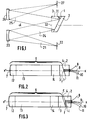
- the first example of embodiment is that of a spectrometer as shown in FIG. 1.
- the network 1 carried by the support 2 receives an input light beam 21 from an entry slot 22, placed at the focal point of an optic 23, producing a parallel beam 24.
- the network 1 returns a parallel beam 25 addressed by an optic 26 to a output slot 27 selecting a particular wavelength by depending on its position in its plane.
- the front blade 3 has a face 31 parallel to the plane of the network 1 and a second face 32, perpendicular to the axis of the system, and approximately perpendicular in the real achievements, both at incident beam 24 and at beam reflected 25. Indeed, for the sake of clarity, the beams 24 and 25 have been shown in Figure 1 as forming an angle ⁇ relatively large. In the realizations, this angle is small allowing the fulfillment of the condition indicated above.
Abstract
Description
La présente invention concerne un système ou multiplexeur-démultiplexeur ou un routeur en longueur d'onde à fibres optiques, susceptible d'être utilisé comme composant dans les installations de télétransmissions par fibres optiques.The present invention relates to a system or multiplexer-demultiplexer or a fiber optic wavelength router, can be used as a component in installations of optical fiber remote transmissions.
On connaít déjà de tels multiplexeurs-démultiplexeurs qui ont été décrits, puis progressivement perfectionnés, en particulier dans les brevets français FR-2.543.768, FR-2.519.148, FR-2.479.981, FR-2.496.260 et dans le brevet européen EP-0.196.963.We already know such multiplexers-demultiplexers which have been described and then progressively refined, especially in French patents FR-2,543,768, FR-2,519,148, FR-2,479,981, FR-2,496,260 and in European patent EP-0.196.963.
Ce dernier document concerne plus particulièrement un multiplexeur-démultiplexeur dans lequel les fibres d'entrée et de sortie sont positionnées au voisinage immédiat du foyer d'un miroir concave. Ainsi, les flux lumineux divergents reçus des fibres d'entrée sont transformés par le miroir concave en des faisceaux de lumière parallèles qui sont adressés sur un réseau de diffraction plan, qui dirige les faisceaux parallèles en retour vers le miroir concave et qui les focalise sur les extrémités des fibres de sortie.This last document relates more particularly to a multiplexer-demultiplexer in which the input and outlet are positioned in the immediate vicinity of the focus of a mirror concave. Thus, the divergent light fluxes received from the fibers input are transformed by the concave mirror into beams of parallel light which are addressed on a diffraction grating plane, which directs the parallel beams back to the mirror concave and which focuses them on the ends of the output fibers.
On a cherché à réduire les aberrations et, en particulier, les aberrations sphériques d'un tel système et c'est ainsi qu'il a été proposé un tel multiplexeur-démultiplexeur comportant un élément porte-fibre, un élément portant le réseau de diffraction, un élément intermédiaire et un élément miroir sphérique. L'élément porte-fibre met les extrémités des fibres en contact avec l'élément portant le réseau de diffraction, l'élément intermédiaire qui est en contact avec le réseau de diffraction et a le même indice optique que l'élément qui le porte, se termine par une face sphérique qui est en contact avec le miroir.We tried to reduce the aberrations and, in particular, the spherical aberrations of such a system and this is how it was proposed such a multiplexer-demultiplexer comprising an element fiber holder, an element carrying the diffraction grating, an element intermediate and a spherical mirror element. The fiber element puts the ends of the fibers in contact with the element carrying the diffraction grating, the intermediate element which is in contact with the diffraction grating and has the same optical index as the element which carries it, ends with a spherical face which is in contact with the mirror.
Ce dispositif donne satisfaction, a permis et permet encore de nombreuses réalisations.This system is satisfactory, has enabled and still allows many achievements.
Toutefois, dans certaines applications particulières, on a pu regretter l'instabilité thermique produite par la variation de l'indice des différents éléments qui le composent, avec la température et les variations des propriétés qui peuvent en résulter..However, in certain particular applications, it has been possible regret the thermal instability produced by the variation of the index of the different elements that compose it, with the temperature and variations in properties that may result.
Le but de la présente invention est d'éviter ces inconvénients et donc de proposer un multiplexeur-démultiplexeur présentant les mêmes avantages que celui présenté plus haut, présentant de plus une bonne stabilité thermique.The object of the present invention is to avoid these drawbacks and therefore to propose a multiplexer-demultiplexer presenting the same advantages as that presented above, presenting moreover good thermal stability.
De manière générale, l'invention concerne un système optique à dispersion destiné à être utiliser dans un domaine de longueur d'onde d'un faisceau lumineux, comportant un réseau plan porté par un support ayant un coefficient de dilatation ε.In general, the invention relates to a system dispersion optics intended to be used in a field of wavelength of a light beam, comprising a plane grating carried by a support having a coefficient of expansion ε.
Selon l'invention, il comporte une lame frontale
d'indice n1, transparente dans le domaine de longueur
d'onde, dont l'une des faces est parallèle au plan du réseau, et
telle que la variation de son indice optique n1 avec la température,
Dans différents modes de réalisation présentant chacun leurs avantages particuliers et susceptibles d'être utilisés selon toutes leurs combinaisons techniquement possibles :
- dn1 / dt et ε sont de signes contraires,
- l'autre face de la lame frontale est perpendiculaire à l'axe x, x' du faisceau,
- le support du réseau est en silice à faible dilatation et l'indice n1 de la lame frontale est tel que dn1 / dt < 0,
- la lame frontale d'indice n1 est en BK7,
- la lame frontale d'indice n1 est en SF64A,
- la lame frontale d'indice n1 est en SK16,
- la lame frontale d'indice n1 est en LF5,
- la lame frontale est collée sur le réseau à l'aide d'une colle optique souple.
- le système comprend une deuxième lame en un matériau ayant un coefficient de dilatation voisin de celui du réseau, à faces parallèles et parallèles au réseau, et placée entre la lame frontale et le réseau,
- ladite deuxième lame est faite dans le même matériau que le support du réseau.
- dn 1 / dt and ε are of opposite signs,
- the other face of the front plate is perpendicular to the axis x, x 'of the beam,
- the network support is made of low expansion silica and the index n 1 of the front plate is such that dn 1 / dt <0,
- the frontal blade of index n 1 is in BK7,
- the front blade of index n 1 is made of SF64A,
- the front blade of index n 1 is in SK16,
- the front blade of index n 1 is in LF5,
- the front blade is glued to the network using a flexible optical glue.
- the system comprises a second blade made of a material having a coefficient of expansion close to that of the network, with faces parallel and parallel to the network, and placed between the front blade and the network,
- said second blade is made of the same material as the network support.
Ce dispositif constitue avantageusement un multiplexeur-démultiplexeur ou un routeur en longueur d'onde à fibres optiques comportant le réseau, le support, la lame frontale et un système réfléchissant, comportant lui-même un miroir et un système optique de transmission. Ledit système réfléchissant ayant un foyer, les extrémités des fibres optiques d'entrée et de sortie sont à proximité du foyer. Le système optique de transmission comporte un premier bloc portant le miroir et d'indice n3, un deuxième bloc à faces parallèles d'indice n4, et un troisième bloc à faces parallèles d'indice n5.This device advantageously constitutes a multiplexer-demultiplexer or a wavelength router with optical fibers comprising the network, the support, the front plate and a reflecting system, itself comprising a mirror and an optical transmission system. Said reflecting system having a focal point, the ends of the input and output optical fibers are near the focal point. The optical transmission system comprises a first block carrying the mirror and of index n 3 , a second block with parallel faces of index n 4 , and a third block with parallel faces of index n 5 .
Avantageusement, les premier, deuxième et troisième blocs sont chacun en silice pure.Advantageously, the first, second and third blocks are each made of pure silica.
Le deuxième bloc et le troisième bloc sont en fait une seule pièce.The second block and the third block are actually one room.
L'invention sera décrite ci-après en détail en référence aux dessins annexés dans lesquels :
- la figure 1 est une représentation schématique d'un spectromètre mettant en oeuvre le système optique de l'invention ;
- la figure 2 est une représentation schématique d'un multiplexeur-démultiplexeur réalisé selon un premier mode de réalisation de l'invention ;
- la figure 3 est une représentation schématique d'un multiplexeur-démultiplexeur réalisé selon un deuxième mode de réalisation de l'invention.
- Figure 1 is a schematic representation of a spectrometer implementing the optical system of the invention;
- Figure 2 is a schematic representation of a multiplexer-demultiplexer produced according to a first embodiment of the invention;
- Figure 3 is a schematic representation of a multiplexer-demultiplexer produced according to a second embodiment of the invention.
Il a été constaté que les dispositifs dispersifs à réseau et, en particulier à réseau plan, sont sensibles aux variations thermiques qui peuvent modifier leurs propriétés et affecter leurs performances.It has been found that the network dispersive devices and, in particular to flat network, are sensitive to thermal variations which can modify their properties and affect their performance.
Pour éviter ces inconvénients, il était apparu jusqu'à présent nécessaire de stabiliser la température de ces dispositifs, ce qui engendre des contraintes de coût, de volume et d'encombrement relativement importantes.To avoid these drawbacks, it had appeared so far necessary to stabilize the temperature of these devices, which generates constraints of cost, volume and size relatively large.
Afin d'éviter ces inconvénients, il est proposé ici d'utiliser un réseau formé sur un support en silice à faible dilatation. D'une manière plus générale, on pourra réaliser un réseau pour la mise en oeuvre de l'invention sur un matériau à coefficient d'expansion ou de dilatation ε faible, associé à une lame frontale dont la variation d'indice en fonction de la température dn1 / dt est également faibleIn order to avoid these drawbacks, it is proposed here to use a network formed on a silica support with low expansion. More generally, a network can be produced for the implementation of the invention on a material with a low coefficient of expansion or expansion ε, associated with a front plate whose index variation as a function of the dn 1 / dt temperature is also low
Les variations de température produisent sur le système optique à dispersion de l'invention deux effets distincts.Temperature variations occur on the system dispersion optics of the invention two separate effects.
Une élévation de température du support du réseau entraíne sa dilatation et donc l'augmentation du pas a du réseau.An increase in the temperature of the network support causes its expansion and therefore the increase in the pitch a of the network.
D'autre part, la variation dn1 / dt de l'indice optique n1 de la lame frontale 3, en fonction de la température, modifie ces propriétés réfractives.On the other hand, the variation dn 1 / dt of the optical index n 1 of the front plate 3, as a function of the temperature, modifies these refractive properties.
On a montré qu'il est possible de minimiser cette variation
des propriétés du système optique à dispersion en minimisant la
quantité
De manière générale, cela peut être réalisé en minimisant chacune de ces quantités, ε d'une part, et dn1 / dt ou 1 / n1 x dn1 / dt d'autre part, leur somme étant alors également faible.In general, this can be achieved by minimizing each of these quantities, ε on the one hand, and dn 1 / dt or 1 / n 1 x dn 1 / dt on the other hand, their sum then also being small.
Il est également possible de choisir des matériaux dont le coefficient de dilatation ε d'une part et les variations d'indice en fonction de la température dn1 / dt sont de signes opposés.It is also possible to choose materials whose coefficient of expansion ε on the one hand and the index variations as a function of the temperature dn 1 / dt are of opposite signs.
On obtient alors une somme ε + 1 / n1 x dn1 / dt faible.We then obtain a small sum ε + 1 / n 1 x dn 1 / dt.
Avec un support 2 du réseau 1 en silice, de préférence choisi
pour avoir une faible dilatation ε, on peut utiliser pour la réalisation
de la lame frontale 3, l'un des verres ayant une variation de l'indice
en fonction de la température faible tels que, par exemple, les
verres BK7, SF64A, SK16 ou LF5. With a
Ces désignations sont celles utilisées par la Société SCHOTT. Bien entendu, des matériaux de mêmes propriétés produits par d'autres sociétés sous d'autres dénominations peuvent également être utilisés à cet effet. Il existe des tables de concordance permettant d'identifier aisément les références et dénominations utilisées par les différents fabricants.These designations are those used by the Company SCHOTT. Of course, materials with the same properties produced by other companies under other names may also be used for this purpose. There are tables of concordance allowing easy identification of references and names used by different manufacturers.
Lorsque E est positif et les variations dn1 / dt négatives comme pour les verres BaK2, LF5, SF64A, on obtient de particulièrement bons résultats.When E is positive and the variations dn 1 / dt negative as for the glasses BaK2, LF5, SF64A, we obtain particularly good results.
Le premier exemple de réalisation est celui général d'un
spectromètre tel que représenté sur la figure 1. Le réseau 1 porté
par le support 2 reçoit un faisceau lumineux d'entrée 21 provenant
d'une fente d'entrée 22, placée au foyer d'une optique 23,
produisant un faisceau parallèle 24. Par dispersion, le réseau 1
renvoie un faisceau parallèle 25 adressé par une optique 26 sur une
fente de sortie 27 sélectionnant une longueur d'onde particulière en
fonction de sa position dans son plan.The first example of embodiment is that of a
spectrometer as shown in FIG. 1. The
La lame frontale 3 comporte une face 31 parallèle au plan du
réseau 1 et une deuxième face 32, perpendiculaire à l'axe du
système, et approximativement perpendiculaire dans les
réalisations réelles, à la fois au faisceau incident 24 et au faisceau
réfléchi 25. En effet, pour plus de clarté, les faisceaux 24 et 25 ont
été représentés sur la figure 1 comme formant un angle α
relativement important. Dans les réalisations, cet angle est faible
permettant la réalisation de la condition indiquée plus haut.The front blade 3 has a face 31 parallel to the plane of the
Cette disposition a permis différentes réalisations dans lesquelles on a obtenu un multiplexeur-démultiplexeur tel que représenté sur la figure 2, avec un tirage total de 100 mm environ et un rayon de courbure du miroir sphérique de 239 mm. This arrangement allowed different achievements in which we obtained a multiplexer-demultiplexer such as shown in Figure 2, with a total draft of approximately 100 mm and a radius of curvature of the spherical mirror of 239 mm.
On a utilisé un réseau de 600 traits par millimètre et à l'exception de la lame frontale, les autres éléments, les blocs 1, 2 et 3, ainsi que le support de réseau, ont été réalisés en silice pure qui a un coefficient de dilatation E de 5,2 10-7 K-1 entre 5 et 35°C.We used a network of 600 lines per millimeter and with the exception of the front blade, the other elements, blocks 1, 2 and 3, as well as the network support, were made of pure silica which has a coefficient of expansion E of 5.2 10 -7 K -1 between 5 and 35 ° C.
Les différentes lames frontales qui ont été expérimentées,
sont indiquées dans le tableau suivant :
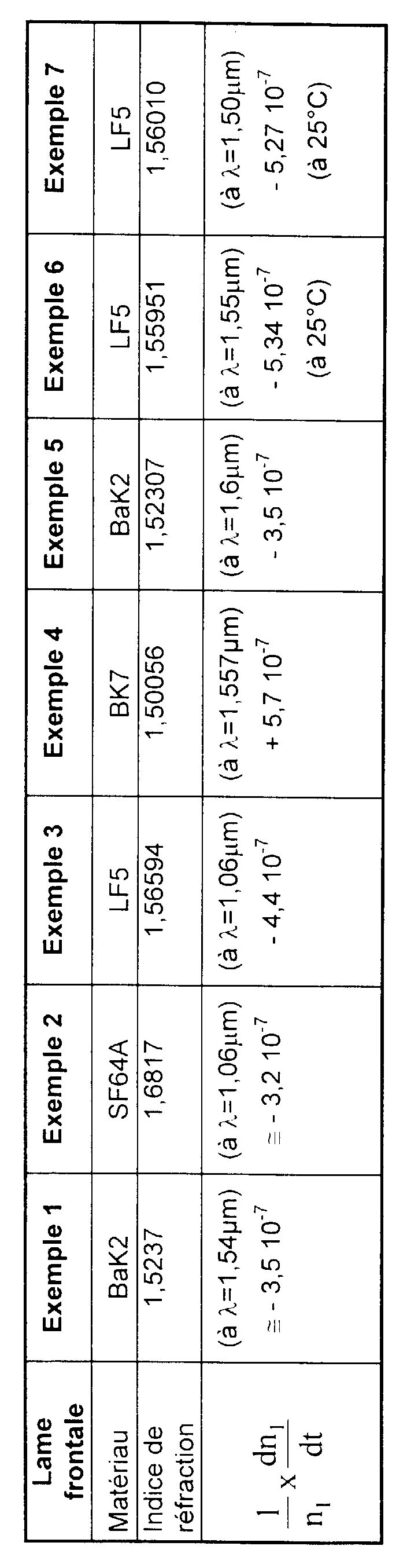
On obtient ainsi, pour ces exemples, une valeur pour l'expression ε + 1 / n1 x dn1 / dt faible et bien inférieure à celle que l'on obtiendrait en utilisant des composants qui soient tous réalisés dans le même matériau, par exemple en silice.We thus obtain, for these examples, a value for the expression ε + 1 / n 1 x dn 1 / dt low and much lower than that which would be obtained by using components which are all made of the same material, by example in silica.
Claims (16)
caractérisé en ce qu'il comporte une lame frontale (3) ayant deux faces, d'indice n1, transparente dans le domaine de longueur d'onde, dont l'une des faces est parallèle au plan du réseau, et telle que la variation de son indice optique n1 avec la température t ε + 1 / n1 x dn1 / dt est petit.Optical dispersion system, intended for use in a wavelength range of a beam, comprising a plane grating (1) carried by a support (2) having a coefficient of expansion ε,
characterized in that it comprises a front plate (3) having two faces, of index n 1 , transparent in the wavelength range, one of the faces of which is parallel to the plane of the grating, and such that the variation of its optical index n 1 with the temperature t ε + 1 / n 1 x dn 1 / dt is small.
que dn1 / dt et ε sont de signes contraires.Optical system according to claim 1, characterized in
that dn 1 / dt and ε are of opposite signs.
Applications Claiming Priority (2)
| Application Number | Priority Date | Filing Date | Title |
|---|---|---|---|
| FR9708886 | 1997-07-11 | ||
| FR9708886A FR2765972B1 (en) | 1997-07-11 | 1997-07-11 | WAVELENGTH-DISPERSION OPTICAL SYSTEM |
Publications (2)
| Publication Number | Publication Date |
|---|---|
| EP0890855A1 true EP0890855A1 (en) | 1999-01-13 |
| EP0890855B1 EP0890855B1 (en) | 2009-07-01 |
Family
ID=9509169
Family Applications (1)
| Application Number | Title | Priority Date | Filing Date |
|---|---|---|---|
| EP98401732A Expired - Lifetime EP0890855B1 (en) | 1997-07-11 | 1998-07-08 | Wavelength dispersion optical system |
Country Status (5)
| Country | Link |
|---|---|
| US (1) | US5991482A (en) |
| EP (1) | EP0890855B1 (en) |
| JP (2) | JP4633206B2 (en) |
| DE (1) | DE69840938D1 (en) |
| FR (1) | FR2765972B1 (en) |
Cited By (1)
| Publication number | Priority date | Publication date | Assignee | Title |
|---|---|---|---|---|
| WO2001020372A2 (en) * | 1999-09-14 | 2001-03-22 | Corning Incorporated | Athermal and high throughput optical gratings |
Families Citing this family (11)
| Publication number | Priority date | Publication date | Assignee | Title |
|---|---|---|---|---|
| US7167615B1 (en) | 1999-11-05 | 2007-01-23 | Board Of Regents, The University Of Texas System | Resonant waveguide-grating filters and sensors and methods for making and using same |
| US6731838B1 (en) | 2000-06-02 | 2004-05-04 | Confluent Photonics Corporation | Athermalization and pressure desensitization of diffraction grating based WDM devices |
| US6556297B1 (en) | 2000-06-02 | 2003-04-29 | Digital Lightwave, Inc. | Athermalization and pressure desensitization of diffraction grating based spectrometer devices |
| US6621958B1 (en) * | 2000-06-02 | 2003-09-16 | Confluent Photonics Corporation | Athermalization and pressure desensitization of diffraction grating based WDM devices |
| US6570652B1 (en) * | 2000-06-02 | 2003-05-27 | Digital Lightwave, Inc. | Athermalization and pressure desensitization of diffraction grating based spectrometer devices |
| US6449097B1 (en) * | 2000-06-05 | 2002-09-10 | Lightchip, Inc. | Diffraction grating for wavelength division multiplexing/demultiplexing devices |
| US6741408B2 (en) | 2000-06-15 | 2004-05-25 | Confluent Photonics Corporation | Thermally stable mounting for a diffraction grating device |
| US6496291B1 (en) * | 2000-10-17 | 2002-12-17 | Intel Corporation | Optical serial link |
| US7408638B2 (en) * | 2001-11-21 | 2008-08-05 | Roygbiv, Llc | Refractive-diffractive spectrometer |
| US6661513B1 (en) * | 2001-11-21 | 2003-12-09 | Roygbiv, Llc | Refractive-diffractive spectrometer |
| EP2083298B1 (en) | 2008-01-23 | 2017-05-10 | Yenista Optics | Optical device comprising a compact dispersing system |
Citations (5)
| Publication number | Priority date | Publication date | Assignee | Title |
|---|---|---|---|---|
| JPS5882219A (en) * | 1981-11-12 | 1983-05-17 | Nec Corp | Light wavelength demultiplexer |
| FR2543768A1 (en) * | 1983-03-31 | 1984-10-05 | Instruments Sa | WAVE LENGTH MULTIPLEXER-DEMULTIPLEXER AND METHOD OF MAKING SAME |
| GB2139374A (en) * | 1983-04-25 | 1984-11-07 | American Telephone & Telegraph | Optical multiplexer/demultiplexer |
| EP0256809A2 (en) * | 1986-08-08 | 1988-02-24 | Corning Glass Works | Optical fiber transmission system having dispersion transformer |
| US5042898A (en) * | 1989-12-26 | 1991-08-27 | United Technologies Corporation | Incorporated Bragg filter temperature compensated optical waveguide device |
Family Cites Families (13)
| Publication number | Priority date | Publication date | Assignee | Title |
|---|---|---|---|---|
| FR2519148B1 (en) * | 1981-12-24 | 1985-09-13 | Instruments Sa | WAVELENGTH SELECTOR |
| NL8104121A (en) * | 1981-09-07 | 1983-04-05 | Philips Nv | TUNABLE OPTICAL DEMULTIPLEX DEVICE. |
| FR2537808A1 (en) * | 1982-12-08 | 1984-06-15 | Instruments Sa | OPTICAL COMPONENT WITH SHARED FUNCTION FOR OPTICAL TELETRANSMISSIONS |
| JPS59137344A (en) * | 1983-01-28 | 1984-08-07 | Nippon Telegr & Teleph Corp <Ntt> | Glass for temperature compensation of refractive index |
| US4729641A (en) * | 1983-06-10 | 1988-03-08 | Canon Kabushiki Kaisha | Functional optical element having a non-flat planar interface with variable-index medium |
| US4571024A (en) * | 1983-10-25 | 1986-02-18 | The United States Of America As Represented By The Secretary Of The Air Force | Wavelength selective demultiplexer tuner |
| FR2579333B1 (en) * | 1985-03-20 | 1987-07-03 | Instruments Sa | WAVELENGTH MULTIPLEXER-DEMULTIPLEXER CORRECTED FOR GEOMETRIC AND CHROMATIC ABERRATIONS |
| NL8700440A (en) * | 1987-02-23 | 1988-09-16 | Philips Nv | OPTICAL DEVICE CONTAINING A HOLDER WITH AN OPTICAL SYSTEM INSERTED THEREIN. |
| JPH0769494B2 (en) * | 1988-09-12 | 1995-07-31 | 横浜国立大学長 | Optical waveguide |
| JP3402401B2 (en) * | 1994-06-03 | 2003-05-06 | 富士写真フイルム株式会社 | Coupling method between guided light and external light |
| JP2861862B2 (en) * | 1995-05-18 | 1999-02-24 | 日本電気株式会社 | Collimating device having a plastic collimating lens |
| JP3209042B2 (en) * | 1995-06-07 | 2001-09-17 | 日立電線株式会社 | Mach-Zehnder optical circuit |
| JPH0943440A (en) * | 1995-07-28 | 1997-02-14 | Toshiba Corp | Integrated optical multiplexer/demultiplexer |
-
1997
- 1997-07-11 FR FR9708886A patent/FR2765972B1/en not_active Expired - Fee Related
- 1997-11-18 US US08/972,243 patent/US5991482A/en not_active Expired - Lifetime
-
1998
- 1998-07-08 EP EP98401732A patent/EP0890855B1/en not_active Expired - Lifetime
- 1998-07-08 DE DE69840938T patent/DE69840938D1/en not_active Expired - Lifetime
- 1998-07-08 JP JP22850098A patent/JP4633206B2/en not_active Expired - Lifetime
-
2010
- 2010-07-02 JP JP2010151829A patent/JP2010211247A/en not_active Withdrawn
Patent Citations (5)
| Publication number | Priority date | Publication date | Assignee | Title |
|---|---|---|---|---|
| JPS5882219A (en) * | 1981-11-12 | 1983-05-17 | Nec Corp | Light wavelength demultiplexer |
| FR2543768A1 (en) * | 1983-03-31 | 1984-10-05 | Instruments Sa | WAVE LENGTH MULTIPLEXER-DEMULTIPLEXER AND METHOD OF MAKING SAME |
| GB2139374A (en) * | 1983-04-25 | 1984-11-07 | American Telephone & Telegraph | Optical multiplexer/demultiplexer |
| EP0256809A2 (en) * | 1986-08-08 | 1988-02-24 | Corning Glass Works | Optical fiber transmission system having dispersion transformer |
| US5042898A (en) * | 1989-12-26 | 1991-08-27 | United Technologies Corporation | Incorporated Bragg filter temperature compensated optical waveguide device |
Non-Patent Citations (1)
| Title |
|---|
| PATENT ABSTRACTS OF JAPAN vol. 007, no. 180 (P - 215) 9 August 1983 (1983-08-09) * |
Cited By (3)
| Publication number | Priority date | Publication date | Assignee | Title |
|---|---|---|---|---|
| WO2001020372A2 (en) * | 1999-09-14 | 2001-03-22 | Corning Incorporated | Athermal and high throughput optical gratings |
| WO2001020372A3 (en) * | 1999-09-14 | 2001-09-27 | Corning Inc | Athermal and high throughput optical gratings |
| US6693745B1 (en) | 1999-09-14 | 2004-02-17 | Corning Incorporated | Athermal and high throughput gratings |
Also Published As
| Publication number | Publication date |
|---|---|
| FR2765972B1 (en) | 1999-09-24 |
| DE69840938D1 (en) | 2009-08-13 |
| US5991482A (en) | 1999-11-23 |
| JP4633206B2 (en) | 2011-02-16 |
| FR2765972A1 (en) | 1999-01-15 |
| JPH11125733A (en) | 1999-05-11 |
| JP2010211247A (en) | 2010-09-24 |
| EP0890855B1 (en) | 2009-07-01 |
Similar Documents
| Publication | Publication Date | Title |
|---|---|---|
| EP0138698B1 (en) | Optical wavelength division multiplexer-demultiplexer for bidirectional communication | |
| EP0005683B1 (en) | Process of manufacturing a planar-convex microlens on at least one end face of an optical fiber, the lens being bonded with its planar face to said end face | |
| CA1115102A (en) | Fixed optical attenuator for light rays guided by optical fiber | |
| EP0890855A1 (en) | Wavelength dispersion optical system | |
| EP0121482A1 (en) | Wavelength multiplexer-demultiplexer and method of producing such an assembly | |
| FR2777359A1 (en) | CONNECTION OF OPTICAL FIBER AND OPTICAL WAVEGUIDE BY MERGER | |
| CA2066549C (en) | Optical amplifier operating in the 1.26-1.34 .mu.m range | |
| EP0962792B1 (en) | Compact multiplexer | |
| FR2488455A1 (en) | DEVICE HAVING A SEMICONDUCTOR LASER DIODE | |
| FR2629219A1 (en) | OPTICAL FIBER COUPLER IN STAR AND ACTIVE TYPE | |
| FR2834565A1 (en) | DEVICE FOR ENTERING AND / OR EXTINGUISHING OPTICAL SIGNALS INTO A LIGHT WAVEGUIDE | |
| EP0884615B1 (en) | Fibre optic wavelength division multiplexer-demultiplexer | |
| FR2505056A1 (en) | OPTICAL SIGNAL COUPLER-EXTRACTOR DEVICE | |
| FR2661513A3 (en) | OPTICAL FIBER FUNCTION. | |
| EP0887672A1 (en) | Fibre-optic wavelength division multiplexer-demultiplexer | |
| FR2794871A1 (en) | COLLECTIVE PROCESS FOR THE COLLECTIVE REALIZATION OF MICRO-LENSES AT THE END OF AN ASSEMBLY OF OPTICAL FIBERS OF THE FIBER TAPE TYPE | |
| WO2012010776A1 (en) | Method for splicing optical fibres and joint obtained by means of such a method | |
| EP0200613A1 (en) | Optical multiplexer/demultiplexer and method of manufacturing it | |
| EP1433006B1 (en) | Optical component with spectral separation | |
| FR2570840A1 (en) | OPTICAL COUPLER | |
| FR2738921A1 (en) | Optical coupler with optical isolator independent of polarisation | |
| FR2860599A1 (en) | Optical coupler device for e.g. multi-core single mode fiber, has section of pure silicon fiber welded to free end of section of index gradient fiber and/or inserted between end of multi-core fiber and end of index gradient fiber | |
| EP1063546A1 (en) | Method of stabilization and wavelength tuning of Bragg gratings | |
| FR2758399A1 (en) | Improved output level fibre=optic collector for power laser diodes | |
| FR2535555A1 (en) | Device for long-range transmission by optical fibre. |
Legal Events
| Date | Code | Title | Description |
|---|---|---|---|
| PUAI | Public reference made under article 153(3) epc to a published international application that has entered the european phase |
Free format text: ORIGINAL CODE: 0009012 |
|
| AK | Designated contracting states |
Kind code of ref document: A1 Designated state(s): DE FR GB IT |
|
| AX | Request for extension of the european patent |
Free format text: AL;LT;LV;MK;RO;SI |
|
| 17P | Request for examination filed |
Effective date: 19990713 |
|
| AKX | Designation fees paid |
Free format text: DE FR GB IT |
|
| RAP1 | Party data changed (applicant data changed or rights of an application transferred) |
Owner name: HIGHWAVE OPTICAL TECHNOLOGIES |
|
| GRAG | Despatch of communication of intention to grant |
Free format text: ORIGINAL CODE: EPIDOS AGRA |
|
| RAP1 | Party data changed (applicant data changed or rights of an application transferred) |
Owner name: YENISTA OPTICS SA |
|
| 17Q | First examination report despatched |
Effective date: 20041022 |
|
| 17Q | First examination report despatched |
Effective date: 20041022 |
|
| GRAP | Despatch of communication of intention to grant a patent |
Free format text: ORIGINAL CODE: EPIDOSNIGR1 |
|
| GRAC | Information related to communication of intention to grant a patent modified |
Free format text: ORIGINAL CODE: EPIDOSCIGR1 |
|
| GRAS | Grant fee paid |
Free format text: ORIGINAL CODE: EPIDOSNIGR3 |
|
| GRAA | (expected) grant |
Free format text: ORIGINAL CODE: 0009210 |
|
| AK | Designated contracting states |
Kind code of ref document: B1 Designated state(s): DE FR GB IT |
|
| REG | Reference to a national code |
Ref country code: GB Ref legal event code: FG4D Free format text: NOT ENGLISH |
|
| REF | Corresponds to: |
Ref document number: 69840938 Country of ref document: DE Date of ref document: 20090813 Kind code of ref document: P |
|
| PLBE | No opposition filed within time limit |
Free format text: ORIGINAL CODE: 0009261 |
|
| STAA | Information on the status of an ep patent application or granted ep patent |
Free format text: STATUS: NO OPPOSITION FILED WITHIN TIME LIMIT |
|
| 26N | No opposition filed |
Effective date: 20100406 |
|
| PG25 | Lapsed in a contracting state [announced via postgrant information from national office to epo] |
Ref country code: IT Free format text: LAPSE BECAUSE OF FAILURE TO SUBMIT A TRANSLATION OF THE DESCRIPTION OR TO PAY THE FEE WITHIN THE PRESCRIBED TIME-LIMIT Effective date: 20090701 |
|
| REG | Reference to a national code |
Ref country code: FR Ref legal event code: PLFP Year of fee payment: 19 |
|
| REG | Reference to a national code |
Ref country code: FR Ref legal event code: PLFP Year of fee payment: 20 |
|
| PGFP | Annual fee paid to national office [announced via postgrant information from national office to epo] |
Ref country code: FR Payment date: 20170728 Year of fee payment: 20 Ref country code: DE Payment date: 20170724 Year of fee payment: 20 Ref country code: GB Payment date: 20170719 Year of fee payment: 20 |
|
| REG | Reference to a national code |
Ref country code: DE Ref legal event code: R071 Ref document number: 69840938 Country of ref document: DE |
|
| REG | Reference to a national code |
Ref country code: GB Ref legal event code: PE20 Expiry date: 20180707 |
|
| PG25 | Lapsed in a contracting state [announced via postgrant information from national office to epo] |
Ref country code: GB Free format text: LAPSE BECAUSE OF EXPIRATION OF PROTECTION Effective date: 20180707 |