EP0890853A1 - Splicing different optical fiber types - Google Patents
Splicing different optical fiber types Download PDFInfo
- Publication number
- EP0890853A1 EP0890853A1 EP98850099A EP98850099A EP0890853A1 EP 0890853 A1 EP0890853 A1 EP 0890853A1 EP 98850099 A EP98850099 A EP 98850099A EP 98850099 A EP98850099 A EP 98850099A EP 0890853 A1 EP0890853 A1 EP 0890853A1
- Authority
- EP
- European Patent Office
- Prior art keywords
- fiber
- indices
- hot
- heating
- determined
- Prior art date
- Legal status (The legal status is an assumption and is not a legal conclusion. Google has not performed a legal analysis and makes no representation as to the accuracy of the status listed.)
- Ceased
Links
- 239000013307 optical fiber Substances 0.000 title claims abstract description 23
- 239000000835 fiber Substances 0.000 claims abstract description 145
- 238000010438 heat treatment Methods 0.000 claims abstract description 45
- 238000000034 method Methods 0.000 claims abstract description 25
- 230000003287 optical effect Effects 0.000 claims description 17
- 239000000463 material Substances 0.000 claims description 10
- 238000012544 monitoring process Methods 0.000 claims description 8
- 239000002019 doping agent Substances 0.000 claims description 7
- 230000001902 propagating effect Effects 0.000 claims description 4
- 230000002035 prolonged effect Effects 0.000 abstract description 9
- 238000003466 welding Methods 0.000 abstract description 6
- 238000012360 testing method Methods 0.000 abstract description 4
- 230000005540 biological transmission Effects 0.000 abstract description 3
- 230000006870 function Effects 0.000 description 12
- 230000008569 process Effects 0.000 description 11
- 239000011162 core material Substances 0.000 description 10
- 238000010586 diagram Methods 0.000 description 7
- 238000009792 diffusion process Methods 0.000 description 5
- 230000008859 change Effects 0.000 description 3
- 238000005253 cladding Methods 0.000 description 3
- 238000012986 modification Methods 0.000 description 3
- 230000004048 modification Effects 0.000 description 3
- 238000012545 processing Methods 0.000 description 3
- RZZPDXZPRHQOCG-OJAKKHQRSA-O CDP-choline(1+) Chemical compound O[C@@H]1[C@H](O)[C@@H](COP(O)(=O)OP(O)(=O)OCC[N+](C)(C)C)O[C@H]1N1C(=O)N=C(N)C=C1 RZZPDXZPRHQOCG-OJAKKHQRSA-O 0.000 description 2
- 230000000881 depressing effect Effects 0.000 description 2
- 238000010891 electric arc Methods 0.000 description 2
- 238000005516 engineering process Methods 0.000 description 2
- 230000004927 fusion Effects 0.000 description 2
- 238000009434 installation Methods 0.000 description 2
- 238000005259 measurement Methods 0.000 description 2
- 238000013459 approach Methods 0.000 description 1
- 230000015556 catabolic process Effects 0.000 description 1
- 238000004891 communication Methods 0.000 description 1
- 238000006731 degradation reaction Methods 0.000 description 1
- 238000009826 distribution Methods 0.000 description 1
- 238000001914 filtration Methods 0.000 description 1
- 238000002844 melting Methods 0.000 description 1
- 230000008018 melting Effects 0.000 description 1
- 238000005457 optimization Methods 0.000 description 1
- 230000008520 organization Effects 0.000 description 1
Images


Classifications
-
- G—PHYSICS
- G02—OPTICS
- G02B—OPTICAL ELEMENTS, SYSTEMS OR APPARATUS
- G02B6/00—Light guides; Structural details of arrangements comprising light guides and other optical elements, e.g. couplings
- G02B6/24—Coupling light guides
- G02B6/255—Splicing of light guides, e.g. by fusion or bonding
- G02B6/2551—Splicing of light guides, e.g. by fusion or bonding using thermal methods, e.g. fusion welding by arc discharge, laser beam, plasma torch
Definitions
- the present invention relates to a method of splicing optical fibers of different or dissimilar types, in particular to automatically selecting a threshold level for matching modefields.
- MFRi mode field radii
- the subscripts 1 and 2 in Eq. 5 represent the left and right fibers of the splice.
- the difference between the refractive indices of the core and the cladding should be higher.
- the higher difference of the refractive indices will result in a higher diffusion speed of the core material as discussed in W. Zheng, O. Hultén and R. Rylander, "Erbium-doped fiber splicing and splice loss estimation.” IEEE J. of Lightwave Technology., Vol. 12, No. 3, pp. 430 - 435, 1994.
- a matching of the mode field diameters of the fibers is made by heating after the very splicing process to make the different materials therein diffuse.
- hot-fiber indices of the two fiber ends are continuously determined. Either one of these indices or a quantity derived thereof is all the time compared to a threshold value and when it is reached the heating is stopped.
- the threshold value has been determined in a preceding stage using test fiber pieces of the same kind in a similar splicing operation comprising a prolonged heating period.
- the transmission of light is constantly measured during the heating and when it has its maximum value the corresponding hot-fiber indices, which are relevant at the same time, are stored and used for deriving the threshold value.
- This method of matching mode field diameters is simple and takes a short time.
- the end surfaces of the fiber ends are positioned opposite, close to and/or at each other.
- Heat for instance from an electric arc generated between two electrodes is applied to a region at the fiber ends to heat them to such a temperature that dopant material of the fibers diffuse, i.e. the cores of the fibers are diffused and made to have a larger diameter in the end portions of the fibers.
- the heating hot-fiber indices of each fiber end are continuously determined or at periodically repeated times having small time intervals therebetween, the intervals being small compared to e.g.
- one of the determined hot-fiber indices or a quantity derived therefrom is compared to some predetermined, suitably chosen threshold level and the application of heat is stopped when the threshold level is achieved.
- first test pieces are provided, the two pieces being taken from fibers identical to each of the two first optical fibers to be spliced.
- a test splicing is made in the same way as described above, i.e. the end surfaces of fiber ends of the two pieces are placed at each other, heat is applied to a region at the fiber ends to heat them to such a temperature that dopant material of the fibers diffuse, and during the heating hot-fiber indices of each fiber end are continuously determined or equivalently at periodically repeated times having small intervals therebetween.
- the optical power and in particular the loss of optical power of light propagating from one piece to the other one is continuously determined or at periodically repeated times having small intervals therebetween.
- a control means monitors the determined values of the optical power or the loss of optical power in order to find a maximum value of the optical power or correspondingly a minimum value of the loss. It records the determined hot-fiber indices determined at the time when the minimum value was determined or it can record a threshold value calculated from these determined hot-fiber indices. Then, in the comparing operation performed during the application of heat to the original fibers to be spliced one of the determined hot-fiber indices or a quantity derived therefrom is compared to a threshold value calculated from the recorded hot-fiber indices or to the recorded threshold value.
- hot-fiber index monitoring technique When using the hot-fiber index monitoring technique, see the cited paper by W. Zheng, O. Hultén et al. and the cited Swedish patent applications, so called hot-fiber indices ⁇ h1 and ⁇ h2 of fibers on the left (1) and right (2) sides of a splice are measured in real time during the process of welding or fusioning two optical fibers to each other.
- the subscript h is here used to distinguish the hot-fiber index ⁇ h from the difference ⁇ of optical refractive indices as used in Eq. (4).
- For the calculation of the hot-fiber index a light intensity profile as taken in a direction perpendicular to the longitudinal direction of a fiber is measured.
- the measured intensity as a function of the distance from the centre line of the fiber is analyzed and low-pass filtered in two steps, one step involving less filtering than the other one.
- the difference between the filtered functions is called the hot-fiber index profile and is related to the distribution of materials in the fiber.
- the height of the central peak of the difference curve or the square root thereof is the hot-fiber index.
- FIG. 2 A typical splicing process which includes a prolonged heating period, the accompanying diffusion of core material into the claddings of the fibers and the corresponding variation of the hot-fiber index profile are illustrated in Fig. 2.
- the hot-fiber index profiles are shown for four different stages of the heating process for fusioning the fibers, the process starting at the top picture for unheated fibers, the lower pictures showing the continuing equalization of the hot-fiber index profiles.
- Fig. 3 a diagram is shown illustrating the hot-fiber indices of the fiber ends and the resulting loss as a function of time during the same heating process.
- the moment of obtaining the minimum loss can be found as shown in Fig. 3 at the dotted line 1 which thus passes through the point of minimum loss. If this moment can be determined in real time, it can then be communicated to a splicing apparatus either from a computer or an operator who can press an appropriate button to command the apparatus to stop the heating.
- This moment corresponds to specific levels of the other two curves, the hot-fiber indices, and since they are easily obtained in real time, the splicing apparatus can use these indices for comparison to suitably set threshold levels in order to find the correct moment of stopping the heating for obtaining minimum loss.
- the time to stop the heating in the case of an arc-welding apparatus using an arc for heating the fiber ends, i.e. the time to stop the supply of current to the welding electrodes, is called the stop point.
- the remaining problem is then to automatically select suitable threshold values, which thus is a key issue in order to make an automated matching of MFDs of two optical fibers to be spliced to each other.
- the criteria for selecting the best quantity to be measured are:
- the importance of the criterion of point 3. is the same as the number order of the point, i.e. it has the lowest significance. Only those variations which meet the first criterion will be considered for the second criterion, and only those variations which meet the second criterion will be considered for the third criterion.
- the corresponding threshold value can be read directly from the measured hot-fiber index data at the stop point.
- the threshold type and value can be saved for the next splice of two fibers of the same kinds as in the splice made. Then this new splice can be easily made without measuring the loss during the heating process.
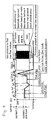
- FIG. 6 an installation is shown for a completely automated MFD matching or threshold selection measuring the loss in real time during the splicing process and a possible prolonged heating period after the very splicing moment.
- a left fiber 3 and a right fiber 5 are thus to be spliced by means of heating in an electrical arc generated between electrodes 7 in an automatic splicing apparatus 9.
- the splicing apparatus 9 is provided with optical monitoring and measuring means such as a video camera and an image processing unit, not shown.
- the end surfaces of the inner ends of the fibers 3, 5 are thus positioned close to and opposite each other in the region between the points of the electrodes 7.
- the other ends of the fibers are connected to a light injecting device and a light detecting device, in the figure a laser 11 being connected to the outer end of the left fiber 3 and a light detector 13 being connected to the outer end of the right fiber 5.
- the light detector 13 can be a "HP8153 Lightwave Multi-Meter" from Hewlett-Packard and is provided with a band pass filter 15 in order to receive only light having the same wavelength as that emitted from the laser source 11 and to stop light emitted by the heated material in the splice region.
- the light detector 13 sends its electrical output signal to a power meter 17, which provides an electrical signal representing the power of the light received by the light detector 13.
- the power signal is received and analyzed by a computer 19.
- the computer 19 is arranged to analyze the power signal in order to find the time when it has a maximum. Thus, when it detects that a maximum is reached, by sensing that the power starts to decrease, it sends an electrical signal to the splicing apparatus 9. The splicing apparatus can then stop immediately the welding process by interrupting the electrical current supplied to the electrodes 7. In any case, the electronic monitoring processor, not shown, of the splicing apparatus 9 which thus all the time makes an automatic image processing of pictures captured of the splicing region, will calculate the quantities described above and in particular the hot-fiber indices of the two fiber end portions.
- the different steps performed by the splicing apparatus 9 during the measurement as described above are also illustrated by the diagram of Fig. 4.
- the electrical current flowing between the welding electrodes 7 and the longitudinal distance between the end surfaces of the fibers to be spliced are plotted as functions of time.
- the ends of the fibers 3, 5 are roughly aligned and then, in a step 43 the arc between the electrodes 7 is ignited during a short time period with a low power to perform a prefusioning of the fiber ends.
- the end surfaces of the fibers are approached to each other to find the mechanical contact position which is recorded in order to be used later in the process.
- the fiber ends are then displaced a small distance from each other in a step 47 and then in a step 49 the fiber ends are accurately aligned with each other.
- step 53 the arc is ignited with a reduced power for preheating the fiber ends.
- step 53 the end surfaces are moved to approach each other up to the point of contact.
- step 55 the main fusion step, the arc is driven normally for making a splice, the power of the arc then being increased significantly to a suitable value.
- step 57 the heating is prolonged in a step 57 for the same power of the electric arc.
- a special button (the button "#") is pressed on a keyboard, not shown, of the splicing apparatus 9, the analyzed values are stored as threshold values to be used in future splices.
- the button can be pressed by an operator looking at a monitor of the computer 19, where the calculated received power or the corresponding loss is graphically represented.
- a signal from the computer 19 can be used for triggering the storing operation of data to be used for threshold levels. This signal can also be used for stopping the prolonged heating. However, as illustrated in Fig. 4, the heating is stopped by manually depressing another special key (the button "*"). After such a depression the procedure is ended.
- a picture as illustrated in Fig. 5 can be displayed on the display window of the splicing apparatus 9.
- graphs similar to those in Fig. 3 except the loss curve, Fig. 5 thus representing the hot-fiber indices of the left and right fibers as functions of time together with the stopping point as selected by depressing the key "#", are displayed. Also mathematically smoothed hot-fiber index curves are shown.
Landscapes
- Physics & Mathematics (AREA)
- Engineering & Computer Science (AREA)
- Plasma & Fusion (AREA)
- General Physics & Mathematics (AREA)
- Optics & Photonics (AREA)
- Mechanical Coupling Of Light Guides (AREA)
- Investigating Or Analysing Materials By Optical Means (AREA)
Abstract
Description
| Fiber type & No. | Producer | Core diameter | MFD | Wavelength |
| SM-027 | SG/ECA | 7.0 mm | 10.4 mm | 1310 nm |
| SM-004 | Optical Fibres | 8.0 mm | 9.8 mm | 1310 nm |
| SM-028 | Fujitsu | 8.0 mm | 9.5 mm | 1310 nm |
| SM-016 | Corning | 7.7 mm | 9.4 mm | 1310 nm |
| SM-006 | AT&T | 7.7 mm | 9.2 mm | 1550 nm |
| DSF-010 | Alcatel | 5.3 mm | 8.0 mm | 1550 nm |
| SM-009 | Ensign Bickford | 5.0 mm | 5.7 mm | 1060 nm |
| SM-010 | Ensign Bickford | 4.4 mm | 5.0 mm | 980 nm |
| EDF-010 | Fujitsu | 3.5 mm | 4.6 mm | 1550 nm |
| SM-021 | Lycom | 3.0 mm | 3.6 mm | 830 nm |
| EDF-002 | Fibercore | 3.2 mm | 1550 nm |
- Fig. 1 is a diagram of the loss of a butt-joint splice as a function of the ratio of the mode field radii of the fibers spliced,
- Fig. 2 is picture illustrating in the left portion thereof the diffusion process as seen in a direction perpendicular to the fibers and in the right portion the change of the refractive index as function of a distance along a line perpendicular to a fiber for four different stages of the heating process for matching the mode field radii of the fibers to each other,
- Fig. 3 is a diagram illustrating the hot-fiber indices of two fiber ends as a function of time during a prolonged heating after making the very splicing operation and the optical loss in the splice made also as a function of time, the change of the hot-fiber indices corresponding to a change of the refractive indices,
- Fig. 4 is a diagram illustrating a process for determining threshold level values in order to match mode field radii,
- Fig. 5 is an image of the variation of the hot-fiber indices as displayed by a practical splicing apparatus after threshold level determination, and
- Fig. 6 is a block diagram of a setup for determining threshold level values used for matching of mode field radii.
Claims (4)
- A method of splicing the ends of two optical fibers of different types to each other, comprising the steps ofcharacterized in that during the application of heat one of the determined hot-fiber indices or a quantity derived therefrom is compared to a predetermined threshold level and that the application of heat is stopped when the threshold level is achieved.positioning end surfaces of the fiber ends at each other,applying heat to a region at the fiber ends to heat them to such a temperature that dopant material of the fibers diffuse,determining during the heating hot-fiber indices of each fiber end continuously or at periodically repeated times having small intervals therebetween,
- A device for splicing the ends of two optical fibers of different types to each other, comprisingcharacterized bypositioning means for positioning end surfaces of the fiber ends at each other,heating means for applying heat to a region at the fiber ends to heat them to such a temperature that dopant material of the fibers diffuse,determining means for determining during the heating hot-fiber indices of each fiber end continuously or at periodically repeated times having small intervals therebetween,control means coupled to the heating means and the determining means comprising comparing means for comparing during the application of heat one of the determined hot-fiber indices or a quantity derived therefrom to a predetermined threshold level,the control means being arranged control the heating means to stop applying heat when the comparing means finds that the threshold level is achieved.
- A method of splicing the ends of two first optical fibers of different types to each other,
characterized by the steps ofproviding two pieces of optical fibers identical to each of the two first optical fibers to be spliced,positioning end surfaces of fiber ends of the two pieces at each other,applying heat to a region at the fiber ends to heat them to such a temperature that dopant material of the fibers diffuse,determining during the heating hot-fiber indices of each fiber end continuously or at periodically repeated times having small intervals therebetween,determining also during the heating the loss of optical power of light propagating from one piece to the other one continuously or at periodically repeated times having small intervals therebetween,monitoring determined values of the loss of optical power in order to find a minimum value of the loss,recording the determined hot-fiber indices determined at the time when the minimum value was determined or recording a threshold value calculated from the determined hot-fiber indices,positioning end surfaces of the ends of the first optical fibers at each other,applying heat to a region at the fiber ends to heat them to such a temperature that dopant material of the fibers diffuse,determining during the heating hot-fiber indices of each fiber end continuously or at periodically repeated times having small intervals therebetween,comparing during the application of heat one of the determined hot-fiber indices or a quantity derived therefrom to a threshold value calculated from the recorded hot-fiber indices or to the recorded threshold value, andstopping the application of heat when the threshold value is achieved. - A device for splicing the ends of two first optical fibers of different types to each other,
characterized bypositioning means for positioning end surfaces of fiber ends of optical fibers at each other,heating means for applying heat to a region at the fiber ends to heat them to such a temperature that dopant material of the fibers diffuse,determining means for determining during the heating hot-fiber indices of each fiber end continuously or at periodically repeated times having small intervals therebetween,light injecting means for injecting light in an optical fiber having an end surface of a fiber end positioned by the positioning means,light detecting means for receiving light from an optical fiber having an end surface of a fiber end positioned by the positioning means for detecting also during the heating the light propagating from the light injecting means to the fiber end and for determining therefrom the loss of optical power of light propagating from one piece to the other one continuously or at periodically repeated times having small intervals therebetween,control means coupled to the heating means, the determining means and the light detecting means for monitoring determined values of the loss of optical power in order to find a minimum value of the loss,the control means comprising memory means for recording the determined hot-fiber indices determined at the time when a minimum value was determined, or the control means comprising calculation means for calculating a threshold value based on the determined hot-fiber indices determined at the time when a minimum value was determined and memory means for storing the threshold value,the control means comprising comparing means for comparing during the application of heat one of the determined hot-fiber indices or a quantity derived therefrom to a threshold value calculated from the recorded hot-fiber indices or to the stored threshold value, andthe control means being arranged control the heating means to stop applying heat when the comparing means finds that the threshold value is achieved.
Applications Claiming Priority (2)
| Application Number | Priority Date | Filing Date | Title |
|---|---|---|---|
| SE9702211A SE511966C2 (en) | 1997-06-09 | 1997-06-09 | Method and apparatus for jointing the ends of two optical fibers of different type with each other |
| SE9702211 | 1997-06-09 |
Publications (1)
| Publication Number | Publication Date |
|---|---|
| EP0890853A1 true EP0890853A1 (en) | 1999-01-13 |
Family
ID=20407322
Family Applications (1)
| Application Number | Title | Priority Date | Filing Date |
|---|---|---|---|
| EP98850099A Ceased EP0890853A1 (en) | 1997-06-09 | 1998-06-09 | Splicing different optical fiber types |
Country Status (4)
| Country | Link |
|---|---|
| US (1) | US6062743A (en) |
| EP (1) | EP0890853A1 (en) |
| JP (1) | JPH1172645A (en) |
| SE (1) | SE511966C2 (en) |
Cited By (12)
| Publication number | Priority date | Publication date | Assignee | Title |
|---|---|---|---|---|
| EP1094346A1 (en) * | 1999-10-22 | 2001-04-25 | Viveen Limited | Fusion spliced optical fibers |
| EP1174741A1 (en) * | 1999-11-04 | 2002-01-23 | Sumitomo Electric Industries, Ltd. | Optical transmission line |
| EP1174740A1 (en) * | 2000-07-21 | 2002-01-23 | Corning Incorporated | Method and apparatus for splicing optical fibers having different mode field diameters |
| WO2002073262A1 (en) * | 2001-03-13 | 2002-09-19 | Ccs Technology, Inc. | Splicing device and method for controlling a thermal splicing process |
| EP1267185A2 (en) * | 2001-06-12 | 2002-12-18 | The Furukawa Electric Co., Ltd. | Optical fiber splicing method |
| US6565269B2 (en) | 2001-02-07 | 2003-05-20 | Fitel Usa Corp. | Systems and methods for low-loss splicing of optical fibers having a high concentration of fluorine to other types of optical fiber |
| EP1335220A2 (en) * | 2002-02-06 | 2003-08-13 | Sumitomo Electric Industries, Ltd. | Cable connecting method and optical fiber connecting member |
| EP1343035A1 (en) * | 2002-03-06 | 2003-09-10 | FITEL USA CORPORATION (a Delaware Corporation) | Systems and methods for low-loss splicing of optical fibers having a high concentration of fluorine to other types of optical fiber |
| WO2004051334A1 (en) * | 2002-12-04 | 2004-06-17 | Telefonaktiebolaget Lm Ericsson (Publ) | Determining mfd of optical fibers |
| US6789960B2 (en) | 2001-07-06 | 2004-09-14 | Corning Incorporated | Method of connecting optical fibers, an optical fiber therefor, and an optical fiber span therefrom |
| US6840682B2 (en) | 1999-10-12 | 2005-01-11 | Sumitomo Electric Industries, Ltd. | Connection unit, optical fiber line unit, optical cable, and optical transmission system |
| WO2008003747A1 (en) * | 2006-07-05 | 2008-01-10 | Ccs Technology, Inc. | Method for operating a device for splicing optical waveguides |
Families Citing this family (15)
| Publication number | Priority date | Publication date | Assignee | Title |
|---|---|---|---|---|
| US20020069677A1 (en) * | 1996-04-29 | 2002-06-13 | Berkey George E. | Optical fiber and method of making optical fiber |
| JP2002510064A (en) * | 1998-03-27 | 2002-04-02 | シーメンス アクチエンゲゼルシヤフト | Method and apparatus for splicing optical waveguides |
| JP3528665B2 (en) * | 1998-10-20 | 2004-05-17 | セイコーエプソン株式会社 | Method for manufacturing semiconductor device |
| US6464410B1 (en) * | 2000-06-14 | 2002-10-15 | Ciena Corporation | Attenuation splice, system and method therefor using estimation algorithm and closed loop intelligent control |
| US6478482B1 (en) * | 2000-06-14 | 2002-11-12 | Ciena Corporation | Attenuating splice, system, and method therefor |
| JP2002131558A (en) * | 2000-10-20 | 2002-05-09 | Sumitomo Electric Ind Ltd | Optical fiber element and its manufacturing method |
| AU2002211990A1 (en) * | 2000-10-24 | 2002-05-06 | Australian Photonics Pty Limited | Method for optical fibre manufacture |
| SE518464C2 (en) * | 2001-02-14 | 2002-10-15 | Ericsson Telefon Ab L M | Method and apparatus for producing an optical attenuator |
| AU782604B2 (en) * | 2001-05-22 | 2005-08-11 | Sumitomo Electric Industries, Ltd. | Method for fusion splicing optical fibers and apparatus for heating spliced part by arc |
| JP2003057481A (en) * | 2001-06-06 | 2003-02-26 | Fujikura Ltd | Machine and method for optical fiber fusion splicing |
| JP3756940B2 (en) * | 2001-07-02 | 2006-03-22 | 古河電気工業株式会社 | Dissimilar optical fiber connecting method and dissimilar optical fiber connecting part heat treatment apparatus |
| DE10352590A1 (en) * | 2002-11-12 | 2004-05-27 | Toptica Photonics Ag | Method for manufacturing optical fibre with output point for stray light and measuring fibre optical power, with optical fibre contiguous core , and surrounding sleeve with second lower refraction index, while fibre section |
| US6991383B2 (en) * | 2003-09-18 | 2006-01-31 | Telefonaktiebolaget Lm Ericsson (Publ) | Fusion splicing of highly rare-earth-doped optical fibers |
| KR101235177B1 (en) * | 2012-09-03 | 2013-02-20 | 일신테크(주) | Optical fiber interface adapter for carrying along |
| EP4024102A4 (en) * | 2019-08-29 | 2022-11-02 | Sumitomo Electric Optifrontier Co., Ltd. | Fusion splicing device and method for operating fusion splicing device |
Citations (2)
| Publication number | Priority date | Publication date | Assignee | Title |
|---|---|---|---|---|
| SE502290C2 (en) * | 1992-06-12 | 1995-09-25 | Ericsson Telefon Ab L M | Optical fibre characteristic properties measurement system - heats area of fibre and measures emitted light intensity |
| SE502374C2 (en) * | 1992-06-12 | 1995-10-09 | Ericsson Telefon Ab L M | Optical fibre splicing system for different type fibres - records intensity of light radiation from heated fibre parts adjacent aligned butting end surfaces |
Family Cites Families (5)
| Publication number | Priority date | Publication date | Assignee | Title |
|---|---|---|---|---|
| US5195151A (en) * | 1990-12-17 | 1993-03-16 | Aster Corporation | Optical fiber couplers and methods of their manufacture |
| FR2695733B1 (en) * | 1992-09-11 | 1994-11-04 | Mars Actel | Methods for preparing the connection by splicing of an optical device integrated into at least one optical cable. |
| TW323341B (en) * | 1995-01-09 | 1997-12-21 | Minnesota Mining & Mfg | |
| US5768452A (en) * | 1996-04-17 | 1998-06-16 | Lucent Technologies Inc. | Radiolytic method for trimming planar waveguide couplers |
| US5757540A (en) * | 1996-09-06 | 1998-05-26 | Lucent Technologies Inc. | Long-period fiber grating devices packaged for temperature stability |
-
1997
- 1997-06-09 SE SE9702211A patent/SE511966C2/en not_active IP Right Cessation
-
1998
- 1998-06-08 US US09/093,033 patent/US6062743A/en not_active Expired - Lifetime
- 1998-06-09 EP EP98850099A patent/EP0890853A1/en not_active Ceased
- 1998-06-09 JP JP10197947A patent/JPH1172645A/en active Pending
Patent Citations (2)
| Publication number | Priority date | Publication date | Assignee | Title |
|---|---|---|---|---|
| SE502290C2 (en) * | 1992-06-12 | 1995-09-25 | Ericsson Telefon Ab L M | Optical fibre characteristic properties measurement system - heats area of fibre and measures emitted light intensity |
| SE502374C2 (en) * | 1992-06-12 | 1995-10-09 | Ericsson Telefon Ab L M | Optical fibre splicing system for different type fibres - records intensity of light radiation from heated fibre parts adjacent aligned butting end surfaces |
Non-Patent Citations (1)
| Title |
|---|
| WENXIN ZHENG: "Low-Loss Splicing Techniques for Erbium-Doped Optical Fibre Amplifiers", ERICSSON REVIEW, vol. 70, no. 2, 1993, pages 71 - 80, XP000385565 * |
Cited By (19)
| Publication number | Priority date | Publication date | Assignee | Title |
|---|---|---|---|---|
| US6840682B2 (en) | 1999-10-12 | 2005-01-11 | Sumitomo Electric Industries, Ltd. | Connection unit, optical fiber line unit, optical cable, and optical transmission system |
| EP1094346A1 (en) * | 1999-10-22 | 2001-04-25 | Viveen Limited | Fusion spliced optical fibers |
| US6336749B1 (en) | 1999-10-22 | 2002-01-08 | Viveen Limited | Jointed optical fibers |
| EP1174741A1 (en) * | 1999-11-04 | 2002-01-23 | Sumitomo Electric Industries, Ltd. | Optical transmission line |
| EP1174741A4 (en) * | 1999-11-04 | 2005-11-09 | Sumitomo Electric Industries | Optical transmission line |
| EP1174740A1 (en) * | 2000-07-21 | 2002-01-23 | Corning Incorporated | Method and apparatus for splicing optical fibers having different mode field diameters |
| US6565269B2 (en) | 2001-02-07 | 2003-05-20 | Fitel Usa Corp. | Systems and methods for low-loss splicing of optical fibers having a high concentration of fluorine to other types of optical fiber |
| WO2002073262A1 (en) * | 2001-03-13 | 2002-09-19 | Ccs Technology, Inc. | Splicing device and method for controlling a thermal splicing process |
| EP1267185A2 (en) * | 2001-06-12 | 2002-12-18 | The Furukawa Electric Co., Ltd. | Optical fiber splicing method |
| US6860119B2 (en) | 2001-06-12 | 2005-03-01 | The Furukawa Electric Co., Ltd. | Optical fiber splicing method |
| EP1267185A3 (en) * | 2001-06-12 | 2003-12-17 | The Furukawa Electric Co., Ltd. | Optical fiber splicing method |
| US6789960B2 (en) | 2001-07-06 | 2004-09-14 | Corning Incorporated | Method of connecting optical fibers, an optical fiber therefor, and an optical fiber span therefrom |
| EP1335220A3 (en) * | 2002-02-06 | 2004-01-14 | Sumitomo Electric Industries, Ltd. | Cable connecting method and optical fiber connecting member |
| EP1335220A2 (en) * | 2002-02-06 | 2003-08-13 | Sumitomo Electric Industries, Ltd. | Cable connecting method and optical fiber connecting member |
| EP1343035A1 (en) * | 2002-03-06 | 2003-09-10 | FITEL USA CORPORATION (a Delaware Corporation) | Systems and methods for low-loss splicing of optical fibers having a high concentration of fluorine to other types of optical fiber |
| WO2004051334A1 (en) * | 2002-12-04 | 2004-06-17 | Telefonaktiebolaget Lm Ericsson (Publ) | Determining mfd of optical fibers |
| US7245360B2 (en) | 2002-12-04 | 2007-07-17 | Telefonaktiebolaget Lm Ericsson (Publ) | Determining MFD of optical fibers |
| CN100354668C (en) * | 2002-12-04 | 2007-12-12 | 艾利森电话股份有限公司 | Determining MFD of optical fibers |
| WO2008003747A1 (en) * | 2006-07-05 | 2008-01-10 | Ccs Technology, Inc. | Method for operating a device for splicing optical waveguides |
Also Published As
| Publication number | Publication date |
|---|---|
| US6062743A (en) | 2000-05-16 |
| SE9702211D0 (en) | 1997-06-09 |
| JPH1172645A (en) | 1999-03-16 |
| SE9702211L (en) | 1998-12-10 |
| SE511966C2 (en) | 1999-12-20 |
Similar Documents
| Publication | Publication Date | Title |
|---|---|---|
| US6062743A (en) | Splicing different optical fiber types | |
| US5090802A (en) | Optical measurement system | |
| EP0697117B1 (en) | Controlled splicing of optical fibers | |
| US4618212A (en) | Optical fiber splicing using leaky mode detector | |
| EP0321947B1 (en) | Method of testing spliced portion of optical fibers | |
| JP4856840B2 (en) | Determining the type of optical fiber | |
| JPH0617923B2 (en) | Optical fiber heating measurement method | |
| US7181111B2 (en) | Apparatus for splicing optical fibers | |
| EP0740171B1 (en) | Optical fiber attenuator | |
| CN100354668C (en) | Determining MFD of optical fibers | |
| US20030108307A1 (en) | Optical attenuator employing a fusion splice | |
| JP4548841B2 (en) | Optical fiber splice loss judgment method | |
| US7131771B2 (en) | Automatic optimization of a splice loss estimator for optical fiber splicers | |
| JP3206607B2 (en) | Optical fiber fusion splicer | |
| EP0687929A1 (en) | Method for manufacturing optical fiber coupler | |
| CN111855145A (en) | Use method of optical fiber macrobend testing device | |
| US7567745B2 (en) | Optical attenuator and method of manufacture | |
| EP1676159A1 (en) | Automatic current selection for single fiber splicing | |
| JP2000205999A (en) | Optical fiber measuring apparatus | |
| Fujise et al. | Core alignments by a simple local monitoring method | |
| JP3461707B2 (en) | Optical fiber identification method | |
| Inada et al. | Splicing of fibers by the fusion method | |
| JPS5857723B2 (en) | Fusion splicing method for single mode optical fiber | |
| Jackson | Mass fusion splicing of optical ribbon fiber: manufacturing process development | |
| JPH095207A (en) | Method for evaluating fusion splicing part of different diameter core optical fibers |
Legal Events
| Date | Code | Title | Description |
|---|---|---|---|
| PUAI | Public reference made under article 153(3) epc to a published international application that has entered the european phase |
Free format text: ORIGINAL CODE: 0009012 |
|
| AK | Designated contracting states |
Kind code of ref document: A1 Designated state(s): DE FR GB IT |
|
| AX | Request for extension of the european patent |
Free format text: AL;LT;LV;MK;RO;SI |
|
| AKX | Designation fees paid |
Free format text: DE FR GB IT |
|
| 17P | Request for examination filed |
Effective date: 19990719 |
|
| RAP1 | Party data changed (applicant data changed or rights of an application transferred) |
Owner name: TELEFONAKTIEBOLAGET LM ERICSSON (PUBL) |
|
| 17Q | First examination report despatched |
Effective date: 20040716 |
|
| APBN | Date of receipt of notice of appeal recorded |
Free format text: ORIGINAL CODE: EPIDOSNNOA2E |
|
| APBR | Date of receipt of statement of grounds of appeal recorded |
Free format text: ORIGINAL CODE: EPIDOSNNOA3E |
|
| APAF | Appeal reference modified |
Free format text: ORIGINAL CODE: EPIDOSCREFNE |
|
| APBT | Appeal procedure closed |
Free format text: ORIGINAL CODE: EPIDOSNNOA9E |
|
| APAM | Information on closure of appeal procedure modified |
Free format text: ORIGINAL CODE: EPIDOSCNOA9E |
|
| STAA | Information on the status of an ep patent application or granted ep patent |
Free format text: STATUS: THE APPLICATION HAS BEEN REFUSED |
|
| 18R | Application refused |
Effective date: 20090211 |