EP0890758A2 - Radial- und Axialfeder mit Wicklungen schräg zur Hauptachse - Google Patents
Radial- und Axialfeder mit Wicklungen schräg zur Hauptachse Download PDFInfo
- Publication number
- EP0890758A2 EP0890758A2 EP98112330A EP98112330A EP0890758A2 EP 0890758 A2 EP0890758 A2 EP 0890758A2 EP 98112330 A EP98112330 A EP 98112330A EP 98112330 A EP98112330 A EP 98112330A EP 0890758 A2 EP0890758 A2 EP 0890758A2
- Authority
- EP
- European Patent Office
- Prior art keywords
- coils
- coil
- major axis
- axis
- spring
- Prior art date
- Legal status (The legal status is an assumption and is not a legal conclusion. Google has not performed a legal analysis and makes no representation as to the accuracy of the status listed.)
- Ceased
Links
- 238000005304 joining Methods 0.000 abstract description 2
- 230000006835 compression Effects 0.000 description 3
- 238000007906 compression Methods 0.000 description 3
- 238000009434 installation Methods 0.000 description 2
- 238000004519 manufacturing process Methods 0.000 description 1
- 238000000034 method Methods 0.000 description 1
- 238000012986 modification Methods 0.000 description 1
- 230000004048 modification Effects 0.000 description 1
- 230000000717 retained effect Effects 0.000 description 1
- 239000000758 substrate Substances 0.000 description 1
- 238000003466 welding Methods 0.000 description 1
- 238000004804 winding Methods 0.000 description 1
Images

Classifications
-
- F—MECHANICAL ENGINEERING; LIGHTING; HEATING; WEAPONS; BLASTING
- F16—ENGINEERING ELEMENTS AND UNITS; GENERAL MEASURES FOR PRODUCING AND MAINTAINING EFFECTIVE FUNCTIONING OF MACHINES OR INSTALLATIONS; THERMAL INSULATION IN GENERAL
- F16F—SPRINGS; SHOCK-ABSORBERS; MEANS FOR DAMPING VIBRATION
- F16F1/00—Springs
- F16F1/02—Springs made of steel or other material having low internal friction; Wound, torsion, leaf, cup, ring or the like springs, the material of the spring not being relevant
- F16F1/04—Wound springs
- F16F1/045—Canted-coil springs
Definitions
- the present application generally relates to canted coil springs and seals and, more particularly, relates to radial and axial springs with coils canting along a major axis thereof.
- the force-deflection characteristics of heretofore available radial and axial springs has been varied by changing numerous spring parameters including wire size, coil height, coil spacing as well as the cant angles, front and back.
- a turn angle of the coils has been utilized to control load deflection characteristics.
- the present invention is directed to springs with coils that cant or slant along a major axis of elliptically shaped coils.
- Coil springs in accordance with the present invention generally include a plurality of deflectable interconnected coils, with each of the coils having an elliptical shape.
- a canted relationship of the coils with the coil center line, which is along a major axis of each coil, provides a means for maximizing a deflection distance of coils.
- the ends of the plurality of coils may be attached to form a circular spring suitable for radial loading with the major axis of the coils being perpendicular to an axis of the circular spring.
- the ends of the plurality of coils may be attached to form a circular spring suitable for axial loading, with the major axis of the coils being parallel to an axis of the circular spring.
- a coil spring assembly in accordance with the present invention generally includes a plurality of deflectable interconnected coils, as hereinabove described, along with retainer means for supporting the coils in a position enabling deflection along the major axis of the coils. Ends of the plurality of coils may be attached to form a continuous spring suitable for axial loading, with the major axis of the coils being parallel to an access of the continuous spring.
- the retainer means may be of various shapes, such as rectilinear or circular.
- retainer means may comprise a groove which provides means for enabling coil deflection along both the major and the minor axes.
- the groove may include parallel side walls having a groove with therebetween smaller than the coil height measured along the coil minor axis.
- a bottom surface may be provided which is at right angles to parallel side walls, or alternatively, at an angle to the parallel side walls.
- the groove bottom may have one portion disposed at a right angle to one of the parallel side walls and the second portion disposed at an angle to another of the parallel side walls.
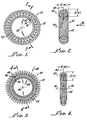
- a canted coil spring 10 in accordance with the present invention which generally includes a plurality of interconnected deflectable coils 12 having ends 14, 16 attached, by welding or the like, at a point 18 in order to form a circular spring 10 suitable for axial loading with a major axis 20 of each coil 12, see Figure 2, parallel to an axis 24 of the coil spring 10 and a loading direction indicated by arrow 26 in Figure 2.
- the coil width, CW is measured along the major axis and a coil height, CH, is measured along a minor axis 30.
- this spring configuration enables the spring 10 to be loaded along the major axis 20 of each coil 12 and as a result, a substantially greater degree of deflection can be obtained than prior art coils in which loading occurs along a minor axis of each coil. It is also important to appreciate that the springs 10, in accordance with the present invention, are wound such that the coils 12 are elliptical which should be contrasted to coils which are forced into an elliptical configuration by loading into a groove or cavity or the like.
- the springs in accordance with the present invention may have various degrees of canting and such coil configuration is taught in the U.S. patents hereinabove recited, which are to be incorporated herewith, intoto, for the purpose of illustrating not only the characteristics of canted coil springs, the parameters describing such springs, but also, methods for manufacture of such springs. Accordingly, such detailed description of each coil configuration is not included herewith for the sake of clarity, and to avoid a duplication of the teachings of the hereinabove referenced U.S. patents.
- Springs in accordance with the present invention may be axial springs 10, shown in Figures 1 and 2, or radial springs 30, shown in Figure 3 and 4.
- the radial springs 30 also include a plurality of deflectable interconnected coils 32 which, as shown in Figure 3, may include ends 34, 36, connected by a weld joint 38, or the like, to form the circular spring 30, which is suitable for radial loading, with a major axis 40, see Figure 4, perpendicular to a spring axis 46 and aligned with a loading direction as indicated by the arrows 48, see Figure 3.
- a coil width, CW is measured along the major axis 40 and a coil height, CH, of each coil 32 is measured along a minor axis 42.
- the increased amount of deflection which may be identified as deflection distance or deflection of length, is most readily appreciated by reference to Figure 4, wherein the elliptical configuration of the coil 32 is most clearly represented. Since the coil width, CW, measured along the major axis 40 in a loading direction 48, is significantly greater than the coil height, CH, measured along the minor axis 42, a greater amount of deflection of the coil 32 is available, i.e., CW, is much greater than CH.
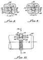
- the spring 60 is disposed in groove 66 shown in a plate 68, with the groove 68 having a groove width, GW, smaller than a coil height, CH.
- This arrangement enables the spring 60 to be held in the groove 66 by compression of the coil 62 along a minor axis 70. Loading of the coils 62 then occurs in a loading direction as indicated by the arrow 72 in Figure 6.
- Figures 7, 8 and 9, respectively, show axial coil springs 80, 82, 84, with coils 86, 88, 90 as loaded in grooves 92, 94, 96, in substrates 100, 102, 104, respectively.
- Loading is provided by plates 106, 108, 110, respectively, which provides an axial loading on the springs 80-84 and compression of the coils 86, 88, 90 along both major axes 114, 116, 118 thereof, and minor axes 120, 122, 124, respectively.
- the original spring size is shown by the dotted lines 126, 128, 130, respectively.
- the groove 66 provides a retainer means for supporting the coil 62 in a position enabling deflection along the major axis 64 of the coil 62
- the grooves 92, 94, 96 provide retainer means for supporting the coils 86, 88, 90 in a position enabling deflection along both the major axis 114, 116, 118 and the minor axis 120, 122, 124 of the coils 86, 88, 90.
- the groove may be rectilinear in shape as shown in Figure 5, or conformed to the springs 10, 30 as shown in Figures 1 and 3, respectively, assuming a circular shape.
- the grooves 92, 94, 96 have a groove width, GW, which is smaller than a coil height, measured along the coil minor axes.
- a bottom 134 of the groove 92 may be disposed at right angles to generally parallel side walls 136, 138.
- a groove bottom 140 may include a portion 142 at right angles to a side wall 144 and another portion 146 disposed at an angle to an opposing side wall 148.
- a bottom 150 of groove 96 as shown in Figure 9 may be disposed at an angle to opposing side walls 152 to 154.
- the radial spring 30 as it may be installed in a radial groove 158 in a cylinder 160, the groove as shown includes generally parallel side walls 162, 164 with a bottom surface 166 therebetween, which is disposed at right angles with the side walls 162, 164.
- the groove 158 may include various bottom surface configurations, not shown, in Figure 10, but similar to those illustrated in Figures 7-9.
- the spring 30 is not shown in a loaded relationship in Figure 10. However, the spring 30 is retained within the groove 158 by compression of the coils 32 along a minor axis 170 thereof which aligns a major axes 172 for loading as indicated by the arrows 174.
- a coiled spring includes a plurality of deflectable interconnected coils, each having an elliptical shape and a canted relationship with the coil centerline with the canted relationship being along a major axis of each coil.
- a circular spring suitable for radial loading may be formed by joining ends of the coils in order that a major axis of the coils is perpendicular to an axis of the circular spring. Ends of the plurality of coils may also be attached to form a circular spring suitable for axial loading, with the major axis of the coils being parallel to an axis of the circular spring.
Landscapes
- Engineering & Computer Science (AREA)
- General Engineering & Computer Science (AREA)
- Mechanical Engineering (AREA)
- Springs (AREA)
Applications Claiming Priority (2)
| Application Number | Priority Date | Filing Date | Title |
|---|---|---|---|
| US888573 | 1992-05-26 | ||
| US88857397A | 1997-07-07 | 1997-07-07 |
Publications (2)
| Publication Number | Publication Date |
|---|---|
| EP0890758A2 true EP0890758A2 (de) | 1999-01-13 |
| EP0890758A3 EP0890758A3 (de) | 2000-11-22 |
Family
ID=25393444
Family Applications (1)
| Application Number | Title | Priority Date | Filing Date |
|---|---|---|---|
| EP98112330A Ceased EP0890758A3 (de) | 1997-07-07 | 1998-07-03 | Radial- und Axialfeder mit Wicklungen schräg zur Hauptachse |
Country Status (2)
| Country | Link |
|---|---|
| EP (1) | EP0890758A3 (de) |
| JP (1) | JPH1172130A (de) |
Cited By (10)
| Publication number | Priority date | Publication date | Assignee | Title |
|---|---|---|---|---|
| US7677915B2 (en) | 2003-12-29 | 2010-03-16 | Areva T&D Sa | Electrical contact element for medium or high voltage electrical equipment, and corresponding, method and equipment |
| EP2178176A1 (de) | 2008-10-15 | 2010-04-21 | Areva T&D Sas | Verfahren zur Herstellung einer elektrischen Verbindung zwischen zwei Kontaktblöcken, sowie entsprechende Verbindungsvorrichtung und entsprechende Mittel- oder Hochspannungsgeräte |
| EP2325519A1 (de) * | 2011-03-15 | 2011-05-25 | Baumann Federn AG | Federring mit gekippten Windungen |
| WO2011034959A3 (en) * | 2009-09-15 | 2011-07-28 | Bal Seal Engineering, Inc. | Variable canted coil spring cross section |
| CN102834639A (zh) * | 2010-04-22 | 2012-12-19 | 美国圣戈班性能塑料公司 | 用于多股斜置式螺形弹簧的系统、方法以及装置 |
| WO2014117093A1 (en) * | 2013-01-25 | 2014-07-31 | Bal Seal Engineering, Inc. | Coil springs with complex coil configurations, assemblies with coil springs, and related methods |
| US9488277B2 (en) | 2011-03-10 | 2016-11-08 | Waters Technologies Corporation | Seal assemblies for reciprocating and rotary applications |
| EP3318293A1 (de) | 2016-11-04 | 2018-05-09 | Berlin Heart GmbH | System zum sichern einer lösbaren verbindung zwischen zwei elementen |
| US10487899B2 (en) | 2016-02-17 | 2019-11-26 | Nelson Products, Inc. | Canted coil spring shock absorber |
| US10995812B2 (en) | 2019-02-27 | 2021-05-04 | Nelson Products, Inc. | Canted coil spring shock absorber |
Families Citing this family (1)
| Publication number | Priority date | Publication date | Assignee | Title |
|---|---|---|---|---|
| US20100289198A1 (en) * | 2009-04-28 | 2010-11-18 | Pete Balsells | Multilayered canted coil springs and associated methods |
Citations (22)
| Publication number | Priority date | Publication date | Assignee | Title |
|---|---|---|---|---|
| US4655462A (en) | 1985-01-07 | 1987-04-07 | Peter J. Balsells | Canted coiled spring and seal |
| US4800344A (en) | 1985-03-21 | 1989-01-24 | And Yet, Inc. | Balun |
| US4826144A (en) | 1988-04-25 | 1989-05-02 | Peter J. Balsells | Inside back angle canted coil spring |
| US4876781A (en) | 1988-04-25 | 1989-10-31 | Peter J. Balsells | Method of making a garter-type axially resilient coiled spring |
| US4893795A (en) | 1988-08-15 | 1990-01-16 | Peter J. Balsells | Radially loaded canted coiled spring with turn angle |
| US4907788A (en) | 1988-04-25 | 1990-03-13 | Peter J. Balsells | Dual concentric canted-coil spring apparatus |
| US4915366A (en) | 1988-04-25 | 1990-04-10 | Peter J. Balsells | Outside back angle canted coil spring |
| US4934666A (en) | 1988-04-25 | 1990-06-19 | Peter J. Balsells | Coiled spring electromagnetic shielding gasket |
| US4961253A (en) | 1988-04-25 | 1990-10-09 | Peter J. Balsells | Manufacturing method for canted-coil spring with turn angle and seal |
| US4964204A (en) | 1988-04-25 | 1990-10-23 | Peter J. Balsells | Method for making a garter-type axially-resilient coil spring |
| US4974821A (en) | 1988-04-25 | 1990-12-04 | Peter J. Balsells | Canted-coil spring with major axis radial loading |
| US5061806A (en) | 1987-07-06 | 1991-10-29 | Merck & Co., Inc. | Phosphinic acid derivatives |
| US5072070A (en) | 1989-12-01 | 1991-12-10 | Peter J. Balsells | Device for sealing electromagnetic waves |
| US5079388A (en) | 1989-12-01 | 1992-01-07 | Peter J. Balsells | Gasket for sealing electromagnetic waves |
| US5108078A (en) | 1988-04-25 | 1992-04-28 | Peter J. Balsells | Canted-coil spring loaded while in a cavity |
| US5117066A (en) | 1988-04-25 | 1992-05-26 | Peter J. Balsells | Retaining and locking electromagnetic gasket |
| US5134244A (en) | 1988-04-25 | 1992-07-28 | Peter J. Balsells | Electromagnetic shielding seal for rotary/reciprocating shaft |
| US5139243A (en) | 1990-07-30 | 1992-08-18 | Peter J. Balsells | Axial canted coil springs in sinusoidal form |
| US5170122A (en) | 1991-07-25 | 1992-12-08 | General Electric | NMR imaging using flow compensated SSFP pulse sequences |
| US5203849A (en) | 1990-03-20 | 1993-04-20 | Balsells Peter J | Canted coil spring in length filled with an elastomer |
| US5503375A (en) | 1994-11-09 | 1996-04-02 | Bal Seal Engineering Company, Inc. | Coil spring with ends adapted for coupling without welding |
| US5545842A (en) | 1993-10-26 | 1996-08-13 | Bal Seal Engineering Company, Inc. | Radially mounted spring to connect, lock and unlock, and for snap-on fastening, and for mechanical, electromagnetic shielding, electrical conductivity, and thermal dissipation with environmental sealing |
Family Cites Families (2)
| Publication number | Priority date | Publication date | Assignee | Title |
|---|---|---|---|---|
| US5139276A (en) * | 1988-04-25 | 1992-08-18 | Peter J. Balsells | Canted coil spring radially loaded while in a cavity |
| EP0437227A3 (en) * | 1990-01-08 | 1991-10-09 | Peter J. Balsells | Canted coil spring assembly and method |
-
1998
- 1998-07-03 JP JP18900998A patent/JPH1172130A/ja not_active Withdrawn
- 1998-07-03 EP EP98112330A patent/EP0890758A3/de not_active Ceased
Patent Citations (22)
| Publication number | Priority date | Publication date | Assignee | Title |
|---|---|---|---|---|
| US4655462A (en) | 1985-01-07 | 1987-04-07 | Peter J. Balsells | Canted coiled spring and seal |
| US4800344A (en) | 1985-03-21 | 1989-01-24 | And Yet, Inc. | Balun |
| US5061806A (en) | 1987-07-06 | 1991-10-29 | Merck & Co., Inc. | Phosphinic acid derivatives |
| US4974821A (en) | 1988-04-25 | 1990-12-04 | Peter J. Balsells | Canted-coil spring with major axis radial loading |
| US5134244A (en) | 1988-04-25 | 1992-07-28 | Peter J. Balsells | Electromagnetic shielding seal for rotary/reciprocating shaft |
| US4907788A (en) | 1988-04-25 | 1990-03-13 | Peter J. Balsells | Dual concentric canted-coil spring apparatus |
| US4915366A (en) | 1988-04-25 | 1990-04-10 | Peter J. Balsells | Outside back angle canted coil spring |
| US4934666A (en) | 1988-04-25 | 1990-06-19 | Peter J. Balsells | Coiled spring electromagnetic shielding gasket |
| US4961253A (en) | 1988-04-25 | 1990-10-09 | Peter J. Balsells | Manufacturing method for canted-coil spring with turn angle and seal |
| US4964204A (en) | 1988-04-25 | 1990-10-23 | Peter J. Balsells | Method for making a garter-type axially-resilient coil spring |
| US4876781A (en) | 1988-04-25 | 1989-10-31 | Peter J. Balsells | Method of making a garter-type axially resilient coiled spring |
| US4826144A (en) | 1988-04-25 | 1989-05-02 | Peter J. Balsells | Inside back angle canted coil spring |
| US5117066A (en) | 1988-04-25 | 1992-05-26 | Peter J. Balsells | Retaining and locking electromagnetic gasket |
| US5108078A (en) | 1988-04-25 | 1992-04-28 | Peter J. Balsells | Canted-coil spring loaded while in a cavity |
| US4893795A (en) | 1988-08-15 | 1990-01-16 | Peter J. Balsells | Radially loaded canted coiled spring with turn angle |
| US5079388A (en) | 1989-12-01 | 1992-01-07 | Peter J. Balsells | Gasket for sealing electromagnetic waves |
| US5072070A (en) | 1989-12-01 | 1991-12-10 | Peter J. Balsells | Device for sealing electromagnetic waves |
| US5203849A (en) | 1990-03-20 | 1993-04-20 | Balsells Peter J | Canted coil spring in length filled with an elastomer |
| US5139243A (en) | 1990-07-30 | 1992-08-18 | Peter J. Balsells | Axial canted coil springs in sinusoidal form |
| US5170122A (en) | 1991-07-25 | 1992-12-08 | General Electric | NMR imaging using flow compensated SSFP pulse sequences |
| US5545842A (en) | 1993-10-26 | 1996-08-13 | Bal Seal Engineering Company, Inc. | Radially mounted spring to connect, lock and unlock, and for snap-on fastening, and for mechanical, electromagnetic shielding, electrical conductivity, and thermal dissipation with environmental sealing |
| US5503375A (en) | 1994-11-09 | 1996-04-02 | Bal Seal Engineering Company, Inc. | Coil spring with ends adapted for coupling without welding |
Cited By (16)
| Publication number | Priority date | Publication date | Assignee | Title |
|---|---|---|---|---|
| US7677915B2 (en) | 2003-12-29 | 2010-03-16 | Areva T&D Sa | Electrical contact element for medium or high voltage electrical equipment, and corresponding, method and equipment |
| EP2178176A1 (de) | 2008-10-15 | 2010-04-21 | Areva T&D Sas | Verfahren zur Herstellung einer elektrischen Verbindung zwischen zwei Kontaktblöcken, sowie entsprechende Verbindungsvorrichtung und entsprechende Mittel- oder Hochspannungsgeräte |
| US8753153B2 (en) | 2009-09-15 | 2014-06-17 | Bal Seal Engineering, Inc. | Variable canted coil spring cross section |
| WO2011034959A3 (en) * | 2009-09-15 | 2011-07-28 | Bal Seal Engineering, Inc. | Variable canted coil spring cross section |
| US8590867B2 (en) | 2009-09-15 | 2013-11-26 | Bal Seal Engineering, Inc. | Variable canted coil spring cross section |
| CN102834639A (zh) * | 2010-04-22 | 2012-12-19 | 美国圣戈班性能塑料公司 | 用于多股斜置式螺形弹簧的系统、方法以及装置 |
| US10302102B2 (en) | 2011-03-10 | 2019-05-28 | Waters Technologies Corporation | Seal assemblies for reciprocating and rotary applications |
| US9488277B2 (en) | 2011-03-10 | 2016-11-08 | Waters Technologies Corporation | Seal assemblies for reciprocating and rotary applications |
| EP2325519A1 (de) * | 2011-03-15 | 2011-05-25 | Baumann Federn AG | Federring mit gekippten Windungen |
| WO2014117093A1 (en) * | 2013-01-25 | 2014-07-31 | Bal Seal Engineering, Inc. | Coil springs with complex coil configurations, assemblies with coil springs, and related methods |
| US9273742B2 (en) | 2013-01-25 | 2016-03-01 | Bal Seal Engineering, Inc. | Coil springs with complex coil configurations, assemblies with coil springs, and related methods |
| US10487899B2 (en) | 2016-02-17 | 2019-11-26 | Nelson Products, Inc. | Canted coil spring shock absorber |
| EP3318293A1 (de) | 2016-11-04 | 2018-05-09 | Berlin Heart GmbH | System zum sichern einer lösbaren verbindung zwischen zwei elementen |
| WO2018083203A1 (de) | 2016-11-04 | 2018-05-11 | Berlin Heart Gmbh | System zum sichern einer lösbaren verbindung zwischen zwei elementen |
| US12564710B2 (en) | 2016-11-04 | 2026-03-03 | Berlin Heart Gmbh | System for securing a releasable connection between two elements |
| US10995812B2 (en) | 2019-02-27 | 2021-05-04 | Nelson Products, Inc. | Canted coil spring shock absorber |
Also Published As
| Publication number | Publication date |
|---|---|
| EP0890758A3 (de) | 2000-11-22 |
| JPH1172130A (ja) | 1999-03-16 |
Similar Documents
| Publication | Publication Date | Title |
|---|---|---|
| US10655665B2 (en) | Spring latching connectors | |
| US7055812B2 (en) | Canted coil springs various designs | |
| US8167285B2 (en) | Spring latching connectors radially and axially mounted | |
| US5411348A (en) | Spring mechanism to connect, lock and unlock, members | |
| EP0890758A2 (de) | Radial- und Axialfeder mit Wicklungen schräg zur Hauptachse | |
| EP0649994B1 (de) | Federmechanismus zum Verbinden, Ver- und Entriegeln; Schnappverschluss für mechanische und elektromagnetische Abschirmung, elektrische Leitfähigkeit, thermische Dissipation mit Umgebungsabdichtung | |
| US5139276A (en) | Canted coil spring radially loaded while in a cavity | |
| US4907788A (en) | Dual concentric canted-coil spring apparatus | |
| US4655462A (en) | Canted coiled spring and seal | |
| US20110068523A1 (en) | Longitudinal canted coil spring contacts to facilitate assembly | |
| US20060127170A1 (en) | Spring holding connectors | |
| US5625248A (en) | Piezoelectric buzzer | |
| EP0675296A1 (de) | Kugelgelenk | |
| US4038628A (en) | Electric resistor | |
| US6177631B1 (en) | Module carrier | |
| EP0403206A2 (de) | Kontakt, der mit einer parallel wirkenden Feder versehen ist | |
| US5162003A (en) | Electrical connector with a constant radius of curvature beam | |
| EP0515090A1 (de) | Elektrischer Verbinder mit Plattenrückhalteelementen | |
| EP1223650B1 (de) | Druckdübel zur Haltung elektrischer Kabel | |
| JP3002934U (ja) | スプリング組立体 | |
| EP4212761A1 (de) | Dichtung für ein fahrzeugbauteil | |
| SU1761990A1 (ru) | Неразъемное соединение деталей с нат гом | |
| JP2559262Y2 (ja) | 中空金属シール | |
| KR20240127296A (ko) | 플랫 소켓 접점 디바이스 | |
| JPS6350572B2 (de) |
Legal Events
| Date | Code | Title | Description |
|---|---|---|---|
| PUAI | Public reference made under article 153(3) epc to a published international application that has entered the european phase |
Free format text: ORIGINAL CODE: 0009012 |
|
| AK | Designated contracting states |
Kind code of ref document: A2 Designated state(s): DE FR GB |
|
| AX | Request for extension of the european patent |
Free format text: AL;LT;LV;MK;RO;SI |
|
| PUAL | Search report despatched |
Free format text: ORIGINAL CODE: 0009013 |
|
| AK | Designated contracting states |
Kind code of ref document: A3 Designated state(s): AT BE CH CY DE DK ES FI FR GB GR IE IT LI LU MC NL PT SE |
|
| AX | Request for extension of the european patent |
Free format text: AL;LT;LV;MK;RO;SI |
|
| 17P | Request for examination filed |
Effective date: 20010227 |
|
| AKX | Designation fees paid |
Free format text: DE FR GB |
|
| 17Q | First examination report despatched |
Effective date: 20040407 |
|
| STAA | Information on the status of an ep patent application or granted ep patent |
Free format text: STATUS: THE APPLICATION HAS BEEN REFUSED |
|
| 18R | Application refused |
Effective date: 20040916 |