EP0890414A2 - Lens grinding apparatus - Google Patents
Lens grinding apparatus Download PDFInfo
- Publication number
- EP0890414A2 EP0890414A2 EP98112667A EP98112667A EP0890414A2 EP 0890414 A2 EP0890414 A2 EP 0890414A2 EP 98112667 A EP98112667 A EP 98112667A EP 98112667 A EP98112667 A EP 98112667A EP 0890414 A2 EP0890414 A2 EP 0890414A2
- Authority
- EP
- European Patent Office
- Prior art keywords
- lens
- chamfering
- grinding wheel
- finishing
- edge
- Prior art date
- Legal status (The legal status is an assumption and is not a legal conclusion. Google has not performed a legal analysis and makes no representation as to the accuracy of the status listed.)
- Granted
Links
Images


Classifications
-
- B—PERFORMING OPERATIONS; TRANSPORTING
- B24—GRINDING; POLISHING
- B24B—MACHINES, DEVICES, OR PROCESSES FOR GRINDING OR POLISHING; DRESSING OR CONDITIONING OF ABRADING SURFACES; FEEDING OF GRINDING, POLISHING, OR LAPPING AGENTS
- B24B49/00—Measuring or gauging equipment for controlling the feed movement of the grinding tool or work; Arrangements of indicating or measuring equipment, e.g. for indicating the start of the grinding operation
-
- B—PERFORMING OPERATIONS; TRANSPORTING
- B24—GRINDING; POLISHING
- B24B—MACHINES, DEVICES, OR PROCESSES FOR GRINDING OR POLISHING; DRESSING OR CONDITIONING OF ABRADING SURFACES; FEEDING OF GRINDING, POLISHING, OR LAPPING AGENTS
- B24B17/00—Special adaptations of machines or devices for grinding controlled by patterns, drawings, magnetic tapes or the like; Accessories therefor
- B24B17/10—Special adaptations of machines or devices for grinding controlled by patterns, drawings, magnetic tapes or the like; Accessories therefor involving electrical transmission means only, e.g. controlled by magnetic tape
-
- B—PERFORMING OPERATIONS; TRANSPORTING
- B24—GRINDING; POLISHING
- B24B—MACHINES, DEVICES, OR PROCESSES FOR GRINDING OR POLISHING; DRESSING OR CONDITIONING OF ABRADING SURFACES; FEEDING OF GRINDING, POLISHING, OR LAPPING AGENTS
- B24B27/00—Other grinding machines or devices
- B24B27/0046—Column grinding machines
-
- B—PERFORMING OPERATIONS; TRANSPORTING
- B24—GRINDING; POLISHING
- B24B—MACHINES, DEVICES, OR PROCESSES FOR GRINDING OR POLISHING; DRESSING OR CONDITIONING OF ABRADING SURFACES; FEEDING OF GRINDING, POLISHING, OR LAPPING AGENTS
- B24B9/00—Machines or devices designed for grinding edges or bevels on work or for removing burrs; Accessories therefor
- B24B9/02—Machines or devices designed for grinding edges or bevels on work or for removing burrs; Accessories therefor characterised by a special design with respect to properties of materials specific to articles to be ground
- B24B9/06—Machines or devices designed for grinding edges or bevels on work or for removing burrs; Accessories therefor characterised by a special design with respect to properties of materials specific to articles to be ground of non-metallic inorganic material, e.g. stone, ceramics, porcelain
- B24B9/08—Machines or devices designed for grinding edges or bevels on work or for removing burrs; Accessories therefor characterised by a special design with respect to properties of materials specific to articles to be ground of non-metallic inorganic material, e.g. stone, ceramics, porcelain of glass
- B24B9/14—Machines or devices designed for grinding edges or bevels on work or for removing burrs; Accessories therefor characterised by a special design with respect to properties of materials specific to articles to be ground of non-metallic inorganic material, e.g. stone, ceramics, porcelain of glass of optical work, e.g. lenses, prisms
Definitions
- the present invention relates to a lens grinding apparatus which grinds the periphery of an eyeglass lens.
- An apparatus which grinds an eyeglass lens so that it fits into an eyeglass frame.
- an optician processes the periphery of each eyeglass lens so as to make the periphery coincident with the shape of an eyeglass frame selected by the customer, to form a bevel or a groove, and then mounts the processed lens into the frame.
- the thus grounded lens has an angular portion at front and rear ends of the edge. If such angular portions are left intact, they may possibly hurt the user or become a cause of crack or breakage of the lens. Therefore, it is common practice for lens processors to chamfer edge portions.
- the invention is characterized in that the apparatus has the following configuration.
- reference numeral 1 denotes a main base
- 2 denotes a sub-base that is fixed to the main base 1.
- a lens chuck upper part 100 and a lens chuck lower part 150 hold a lens to be processed by means of their respective chuck shafts during processing it.
- a lens thickness measuring section 400 is accommodated below the lens chuck upper part 100 in the depth of the sub-base 2.
- Reference symbols 300R and 300L respectively represent right and left lens grinding parts each having grinding wheels for lens grinding on its rotary shaft.
- Each of the lens grinding parts 300R and 300L is held by a moving mechanism (described later) so as to be movable in the vertical and horizontal directions with respect to the sub-base 2
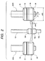
- a rough grinding wheel 30 and a finishing grinding wheel 31 having a bevel groove are mounted on the rotary shaft of the lens grinding part 300L.
- a front surface chamfering grinding wheel 32 having a conical surface is coaxially attached to the upper end surface of the finishing grinding wheel 31, while a rear surface chamfering grinding wheel 33 having a conical surface is coaxially attached to the lower end surface of the rough grinding wheel 30.
- a rough grinding wheel 30, a mirror-finishing (polishing) grinding wheel 34 having a bevel groove, a front surface mirror-chamfering grinding wheel 35 having a conical surface, and a rear surface mirror-chamfering grinding wheel 36 having a conical surface are mounted on the rotary shaft of the lens grinding part 300R coaxially.
- the diameter of these grinding wheels are relatively small, that is, about 60 mm.
- the chamfering surface of each of the chamfering grinding wheels 32, 33, 35 and 36 is 4mm in height and 45° in inclination.
- a display unit 10 for displaying processing data and other information and an input unit 11 for allowing a user to input data or an instruction to the lens grinding apparatus are provided in the front surface of a body of the apparatus.
- Reference numeral 12 denotes a closable door.
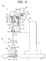
- Fig. 3 illustrates the lens chuck upper part 100 and the lens chuck lower part 150.
- a fixing block 101 is fixed to the sub-base 2.
- a DC motor 103 is mounted on top of the fixing block 101 by means of a mounting plate 102. The rotational force of the DC motor 103 is transmitted through a pulley 104, a timing belt 108 and a pulley 107 to a feed screw 105. As the feed screw 105 is rotated, a chuck shaft holder 120 is vertically moved while being guided by a guide rail 109 fixed to the fixing block 101.
- a pulse motor 130 is fixed to the top portion of the chuck shaft holder 120, so that the rotational force of the pulse motor 130 is transmitted via a gear 131 and a relay gear 132 to a gear 133 to rotate the chuck shaft 121.
- a lower chuck shaft 152 is rotatably held by a chuck shaft holder 151 fixed to the main base 1.
- the rotational force of a pulse motor 156 is transmitted to the chuck shaft 152 to rotate the chuck shaft 152.
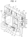
- Fig. 4 illustrates a mechanism for moving the right lens grinding part 300R.
- a vertical slide base 201 is vertically slidable along two guide rails 202 that are fixed to the front surface of the sub-base 2.
- a nut block 206 is fixed to the vertical slide base 201.
- Reference numeral 210 denotes a horizontal slide base to which the lens grinding part 300R is fixed.
- the horizontal slide base 210 is slidable in the horizontal direction along two slide guide rails 211 that are fixed to the front surface of the vertical slide base 201.
- a mechanism for moving the horizontal slide base 210 is basically the same as the above-described moving mechanism for the vertical slide base 201.
- the pulse motor 214R rotates the ball screw 213, so that the horizontal slide base 210 fixed to the nut block 215 is moved accordingly in the horizontal direction along the guide rails 211.
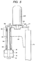
- Fig. 5 is a side sectional view showing the structure of the right lens grinding part 300R.
- a shaft support base 301 is fixed to the horizontal slide base 210.
- a housing 305 is fixed to the front portion of the shaft support base 301, and rotatably holds therein a vertically extending rotary shaft 304.
- a group of grinding wheels including a rough grinding wheel 30 and so on are mounted on the lower portion of the rotary shaft 304.
- a servo motor 310R is fixed to the top surface of the shaft support base 301 through a mounting plate 311, so that the rotational force of the servo motor 310R is transmitted via a pulley 312, a belt 313 and a pulley 306 to the rotary shaft 304, thereby rotating the group of the grinding wheels.
- Fig. 6 illustrates the lens thickness measuring section 400 (Fig. 1).
- the lens thickness measuring section 400 includes a measuring arm 527 having two feelers 523 and 524, a rotation mechanism such as a DC motor (not shown) for rotating the measuring arm 527, a sensor plate 510 and photo-switches 504 and 505 for detecting the rotation of the measuring arm 527 to thereby allow control of the rotation of the DC motor, a detection mechanism such as a potentiometer 506 for detecting the amount of rotation of the measuring arm 527 to thereby obtain the shapes of the front and rear surfaces of the lens.
- the configuration of the lens thickness measuring section 400 is basically the same as that disclosed in Japanese Unexamined Patent Publication No. Hei. 3-20603 and U.S. Patent No.
- the lens thickness (edge thickness) measurement is performed in the following manner.
- the measuring arm 527 is rotated, that is elevated, so that the feeler 523 is brought into contact with the lens front refraction surface.
- the lens is rotated as well as the lens thickness measuring section 400 is controlled to move forward or backward by the front-rear moving means 630, so that the shape of the lens front refraction surface (on the edge of the lens to be formed) is obtained.
- the shape of the lens rear refraction surface is obtained similarly by rotating the lens and by moving the lens thickness measurement section 400 while keeping the feeler 524 in contact with the lens rear refraction surface.
- the lens thickness (edge thickness) is obtained.
- the lens thickness is measured such that the measuring arm 527 is rotated upward from its lower initial position and the feelers 523 and 524 are respectively brought into contact with the front and rear refraction surfaces of the lens. Therefore, it is preferable that the rotary shaft of the measuring arm 527 be equipped with a coil spring or the like which cancels out the downward load of the measuring arm 527.
- Fig. 7 is a block diagram showing a general configuration of a control system of the lens grinding apparatus.
- Reference character 600 denotes a control unit which controls the whole apparatus.
- the display unit 10, input unit 11, micro switch 110, and photosensors are connected to the control unit 600.
- the motors for moving or rotating the respective parts are connected to the control unit 600 via drivers 620-628.
- the drivers 622 and 625 which are respectively connected to the servo motor 310R for the right lens grinding part 300R and the servo motor 310L for the left lens grinding part 300L, detect the torque of the servo motors 310R and 310L during the processing and feed back the detected torque to the control unit 600.
- the control unit 600 uses the torque information to control the movement of the lens grinding parts 300R and 300L as well as the rotation of the lens.
- Reference numeral 601 denotes an interface circuit which serves to transmit and receive data.
- An eyeglass frame shape measuring apparatus 650 (see USP 5,333,412), a host computer 651 for managing lens processing data, a bar code scanner 652, etc. may be connected to the interface circuit 601.
- a main program memory 602 stores a program for operating the lens grinding apparatus.
- a data memory 603 stores data that are supplied through the interface circuit 601, lens thickness measurement data, and other data.
- edge position locus When the edge position locus is to be calculated, two-dimensional process data with respect to the rotation center of the lens are obtained on the basis of the frame shape data obtained by the eyeglass frame shape measuring apparatus 650 and the layout data input through the input unit 11 (processes such as correction of warpage of the frame may be added).
- the lens thickness measuring section 400 By using the lens thickness measuring section 400, the lens shape is measured two times on the basis of the process data and in accordance with different measurement loci.
- the measurement is performed in accordance with the locus of the position of the bevel apex (in the specification, this is referred to as the reference shape) to be formed in the lens.
- This measurement locus can be obtained from the two-dimensional process data based on the frame shape data and the layout data.
- the second measurement is performed in accordance with the shape (the locus) of the bevel bottom (the portion where the bevel slope and the bevel shoulder intersect each other).
- This measurement locus in this case can be obtained in the following manner.
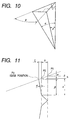
- the line connecting the rotation center of the lens and that of the grinding wheel is indicated as an axis L1
- the line connecting the process point a and the rotation center of the grinding wheel is indicated as a normal L2
- the line connecting the process point a and the rotation center of the lens is indicated as a reference line L3 and the followings are defined:
- the edge locus after the beveling process is obtained on the basis of the data and the edge position information (the edge position locus) obtained by the two lens shape measurements described above.
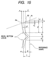
- the edge locus is to be obtained, deviation of the edge position is corrected with respect to the inclination angle which is provided to the finishing grinding wheel in order to form a bevel shoulder.
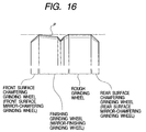
- a correction angle for the lens rear surface inclination with respect to the rear surface inclination angle ⁇ (this value is previously known and stored in the main program memory 602) of the finishing grinding wheel (as shown in Fig. 16) is calculated.
- the inclination angle of the lens bevel shoulder in the direction of the normal L2 becomes as it is to the inclination angle ⁇ .
- the section shape in the direction of the reference line L3 is considered in accordance with the correction angle ⁇ of the rear surface inclination, and the edge position P3 of the lens rear surface after the beveling process is obtained.
- P1 denotes the edge position obtained in the first measurement of the lens edge position
- P2 denotes the edge position obtained in the second measurement.
- h of Fig. 11 is obtained from the result of the measurement of the lens edge position, and ⁇ from the result of the second measurement (the measurement result at the bevel bottom) and the bevel calculation result.
- peripheral length correction the peripheral length of the bevel curve locus is approximately obtained by calculating distances among the bevel curve locus data obtained in the bevel calculation on the basis of the data, and summing the distances.
- the correction amount can be obtained from the thus obtained peripheral length, and the peripheral length of the eyeglass frame shape which is similarly obtained from the radius vector information of the frame shape.
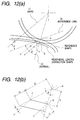
- the calculation of the chamfering process locus which is performed during the chamfering process in order to visually uniformalize the chamfer shape will be described with reference to Fig. 14.
- a fixed chamfering amount from the edge end (P4) in the bevel direction is designated (an offset of a fixed amount is applied)
- the length of the chamfered slope after chamfering (hereinafter, the length is referred to as chamfering width) is changed by influence of the rear surface curve, with the result that the chamfering is visually recognized not to be uniformly performed.
- the chamfering process locus is obtained so that the length of the slope after chamfering is uniform irrespective of the radius vector angle.
- g denotes an offset component of the chamfering amount
- j denotes an offset amount after correction
- f denotes a correction angle of the inclination angle F of the chamfering grinding wheel (a previously known value, and, in the embodiment, 45 degrees) in the direction of the reference line L3
- e denotes a chamfering width in the case where the rear surface of the lens is flat.
- the chamfering width becomes equal in size to the chamfering width d because of the rear surface curve.
- an offset correction amount k is obtained so as to attain the chamfering width which is equal to that in the case where the rear surface of the lens is flat.
- the correction angle f is first obtained.
- the offset correction amount k is obtained as follows:
- the offset correction amount may be expressed as follows:
- the thus obtained position of the chamfering process point Q is information which is obtained without considering the position of the bevel bottom.
- the chamfering process must be performed so as not to interfere with the bevel.
- a process is performed in which the position of the bevel bottom is obtained, the position is compared with the chamfering process point, and, if the chamfering process point Q in the optical axis direction is in the inner side with respect to the position of the bevel bottom, the bevel bottom position is substituted for the chamfering process point.
- the value of the bevel bottom position in the optical axis direction of the lens is obtained by using q and q' obtained by splitting the bevel apex.
- the q and q' are obtained from the shape of the bevel groove of the finishing grinding wheel.
- the chamfering process point Q and the position of the bevel bottom are obtained for the whole periphery in accordance with the radius vector angle, and the chamfering process locus in which the chamfering process does not interfere with the bevel can be obtained.
- the chamfering process locus on the side of the front surface of the lens can be obtained in the same method.
- the chamfering process locus can be obtained in a basically same concept.
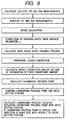
- the optician measures the shape of an eyeglass frame (template) by using the eyeglass frame shape measuring apparatus 650, and inputs the measured shape. Thereafter, the optician inputs layout data such as the PD value of the user and the height of the optical center are input with respect to the lens shape based on the eyeglass frame data. Furthermore, a process mode such as the beveling process, the plane process, or a mirror-polish process is input, and instructions relating to the chamfering amount is input.
- the input of the chamfering amount can be performed by means of a ratio (referred to as a chamfering ratio) which is used for splitting the width (the width in the optical axis direction) of the bevel shoulder extending from the bevel bottom to the edge position, in the whole periphery, and the offset amount g shown in Fig. 14.
- a ratio referred to as a chamfering ratio
- the chamfering process position obtained by splitting the width of the bevel shoulder on the basis of the input ratio is shifted by the amount corresponding to the instructions of the offset amount.
- the offset amount g is input.
- the optician performs predetermined processes on the lens to be processed and places the lens on the chuck shaft 152.
- the START switch of the input unit 11 is depressed to start the operation of the apparatus.
- the control unit 600 controls the operations of the front-rear moving means 630 and lens thickness measuring section 400, and the rotation of the chucked lens to be processed.
- Two measurements i.e., the first and second measurements are performed on each of the rear and front refracting surfaces of the lens on the basis of the layout information and the lens frame shape.
- the apparatus performs calculations of the edge and peripheral length correction, so that the edge locus information and the chamfering process locus information are obtained as described above.
- both the right and left rough grinding wheels 30 are moved to the level of the lens to be processed, and the lens grinding parts 300R and 300L are then slid toward the lens to be processed.
- the lens is gradually ground in two directions by moving the right and left lens grinding parts 300R and 300L which are rotating, toward the lens to be processed.
- the movement amounts of the right and left rough grinding wheels 30 toward the lens are independently controlled on the basis of the process data.
- the control unit 600 controls the movements of the finishing grinding wheel 31 (or the finishing grinding wheel 34) in the height of the bevel groove and the lens direction on the basis of beveling process data stored in the data memory 603, thereby performing the beveling process.
- the control unit 600 controls the movements of the front surface chamfering grinding wheel 32 and the rear surface chamfering grinding wheel 33 (or the chamfering grinding wheels 35 and 36 are used) in the vertical directions and the radial direction of the lens on the basis of the chamfering process data stored in the data memory 603.
- the correction is performed so that the length of the chamfered slope is uniform irrespective of the radius vector angle, and hence the chamfering is visually recognized not to be uniformly performed, thereby improving the appearance.
- the edge of a lens is measured by two measurements, i.e., the first and second measurement on the whole periphery. Since the inclination angle of a lens is not abruptly changed, the edge may be measured at intervals of, for example, 15 degrees, and the measurement results may be smoothly interpolated. If the lens data can be obtained from other means, the data may be used. That is to say, lens data of the eyeglass lens or edge position information obtained by measuring different positions with respect to the radius vector may be used as a position variation information to calculate edge positions after a finishing process.
- a chamfering process can be easily performed and the chamfered shape can be finished to a satisfactory one.
Abstract
Description
wherein the chamfering process controlling means controls an operation of the chamfering means on the basis of the chamfering process position obtained by the chamfering process position calculating means.
Claims (11)
- A lens grinding apparatus for grinding the periphery of an eyeglass lens, comprising:data inputting means for inputting shape data of an eyeglass frame and layout data of an eyeglass lens to the eyeglass frame;edge position measuring means for measuring edge positions of front and rear surfaces of the eyeglass lens on the basis of the input data;position variation information inputting means for inputting position variation information of the front and rear surfaces of the lens with respect to a radius vector;inclination angle storing means for storing an inclination angle of a finishing grinding wheel;edge position calculating means for calculating edge positions after a finishing process on the basis of the measured edge positions, the input position variation information, and the inclination angle of the finishing grinding wheel;chamfering means which has a chamfering grinding wheel for chamfering edge portions of a finish-processed eyeglass lens and which moves a shaft of the chamfering grinding wheel relative to a shaft holding the eyeglass lens; andchamfering process controlling means for controlling an operation of said chamfering means on the basis of the edge positions calculated by said edge position calculating means.
- A lens grinding apparatus according to claim 1, wherein said position variation information is lens data of the eyeglass lens or edge position information obtained by measuring different positions with respect to the radius vector by said edge position measuring means.
- A lens grinding apparatus according to claim 1, further comprising:measurement position calculating means for calculating at least first and second measurement positions for measuring edge positions of the same one of the front and rear surfaces of the eyeglass lens on the basis of the data input through said data input means, wherein said position variation information is obtained from a measurement result of said edge position measuring means in accordance with measurement positions calculated by said measurement position calculating means.
- A lens grinding apparatus according to claim 1, further comprising:inclination angle correcting means for correcting the inclination angle of the finishing grinding wheel stored in said inclination angle storing means, on the basis of a positional relationship between a process point of the finishing grinding wheel and a rotation center of the lens.
- A lens grinding apparatus according to claim 1, further comprising:finishing process calculating means for calculating data of a finishing process by the finishing grinding wheel, on the basis of the data input through said data inputting means and the edge positions measured by said edge position measuring means, wherein said edge position calculating means calculates edge positions after the finishing process, on the basis of the finishing process data.
- A lens grinding apparatus according to claim 5, wherein said finishing grinding wheel is a bevel grinding wheel for a beveling process, the finishing process data calculated by said finishing process calculating means include bevel apex locus data, the apparatus further comprises peripheral length correction calculating means for correcting a peripheral length of the bevel apex locus so as to substantially coincide with a peripheral length of the eyeglass frame input through said data inputting means, and wherein said edge position calculating means calculates the edge positions after a finishing process on the basis of a result calculated by said peripheral length correction calculating means.
- A lens grinding apparatus according to claim 1, further comprising:chamfering amount instructing means for instructing a fixed chamfering amount; andchamfering process position calculating means for calculating a chamfering process position where a length of chamfered slope after a chamfering process becomes substantially constant regardless of the radius vector angle, on the basis of the instructed chamfering amount, information of edge position calculated by said edge position calculating means, and an inclination angle of said chamfering grinding wheel, and
wherein said chamfering process controlling means controls an operation of said chamfering means on the basis of the chamfering process position obtained by said chamfering process position calculating means. - A lens grinding apparatus according to claim 7, wherein said chamfering process position calculating means calculates the chamfering process position while using, as a reference, a length of the chamfered slope assumed under a condition that a lens whose lens surface has a predetermined inclination angle is subjected to the chamfering process.
- A lens grinding apparatus for grinding a periphery of an eyeglass lens, comprising:data inputting means for inputting shape data of an eyeglass frame and layout data of an eyeglass lens to the eyeglass frame;first calculating means for calculating at least first and second measurement positions for measuring edge positions of the same one of front and rear surfaces of the eyeglass lens, on the basis of the input data;edge position measuring means for measuring edge positions of the eyeglass lens, in accordance with the first and second measurement positions calculated by said first calculating means;second calculating means for calculating finishing process data for the eyeglass lens on the basis of information of the edge position measured by said edge position measuring means and the data input through said data inputting means;inclination angle storing means for storing an inclination angle of a finishing grinding wheel;a third calculating means for calculating edge positions after the finishing process on the basis of the measured edge position information, the calculated finishing process data, and the inclination angle of the finishing grinding wheel;chamfering means which has a chamfering grinding wheel for chamfering edge portions of a finish-processed eyeglass lens and which moves a shaft of the chamfering grinding wheel relative to a shaft holding the eyeglass lens;a fourth calculating means for calculating a position of the chamfering process by said chamfering means on the basis of the edge positions calculated by said third calculating means; andchamfering process controlling means for controlling an operation of said chamfering means on the basis of a result of the calculation of said fourth calculating means.
- A process for controlling a lens grinding apparatus including a finishing grinding wheel having a finishing conical surface inclined at a first predetermined angle with respect to a grinding wheel rotation axis, a chamfering grinding wheel coaxial arranged with respect said finishing grinding wheel and having a chamfering conical surface inclined at a second predetermined angle with respect to said grinding wheel rotation axis, and a shaft which rotatively holds an eyeglass lens about a lens rotating axis, said process comprising the steps of:a) calculating first correction angles of said first predetermined angle, wherein each of said first correction angles corresponding to an angle of said finishing conical surface in a cross-section taken along a reference line connecting a processing point at a respective radius vector angle to said lens rotation axis;b) calculating a locus of edge positions of the eyeglass lens processed by the finishing conical surface, wherein each of said edge positions being determined in relation to a respective first correction angle in a cross-section taken along a reference line connecting a processing point at a respective radius vector angle to said lens rotation axis;c) calculating second correction angles of said second predetermined angle, wherein each of said second correction angles corresponding to an angle of said chamfering conical surface in a cross-section taken along a reference line connecting an edge position on said locus at a respective radius vector angle to said lens rotation axis;d) calculating a locus of chamfering process points of the eyeglass lens processed by the chamfering conical surface, wherein each of said chamfering process points being determined in relation to a respective second correction angle in a cross-section taken along a reference line connecting an edge position at a respective radius vector angle to said lens rotation axis;e) controlling a distance between said grinding wheel rotation axis and said lens rotation axis on the basis of said locus of edge positions to process said eyeglass lens with said finishing grinding wheel; andf) controlling said distance between said grinding wheel rotation axis and said lens rotation axis on the basis of said locus of said chamfering process points to process said eyeglass lens with said chamfering grinding wheel.
- A process according to claim 10, wherein said step of calculating said locus of edge positions includes modifying each of said edge positions with a correction amount occurring in a cross-section taken along a reference line connecting a processing point at a respective radius vector angle to said lens rotation axis when a peripheral length correction is made along a line connecting said grinding wheel rotation axis to said lens rotation axis.
Applications Claiming Priority (3)
| Application Number | Priority Date | Filing Date | Title |
|---|---|---|---|
| JP199227/97 | 1997-07-08 | ||
| JP19922797A JP4002324B2 (en) | 1997-07-08 | 1997-07-08 | Lens grinding device |
| JP19922797 | 1997-07-08 |
Publications (3)
| Publication Number | Publication Date |
|---|---|
| EP0890414A2 true EP0890414A2 (en) | 1999-01-13 |
| EP0890414A3 EP0890414A3 (en) | 2002-02-13 |
| EP0890414B1 EP0890414B1 (en) | 2014-12-10 |
Family
ID=16404272
Family Applications (1)
| Application Number | Title | Priority Date | Filing Date |
|---|---|---|---|
| EP98112667.5A Expired - Lifetime EP0890414B1 (en) | 1997-07-08 | 1998-07-08 | Lens grinding apparatus |
Country Status (3)
| Country | Link |
|---|---|
| US (1) | US6062947A (en) |
| EP (1) | EP0890414B1 (en) |
| JP (1) | JP4002324B2 (en) |
Cited By (6)
| Publication number | Priority date | Publication date | Assignee | Title |
|---|---|---|---|---|
| US6336057B1 (en) | 1998-04-30 | 2002-01-01 | Nidek Co., Ltd. | Lens grinding apparatus |
| US6478657B1 (en) | 1999-07-07 | 2002-11-12 | Nidek Co., Ltd. | Eyeglass lens processing apparatus |
| WO2012075016A1 (en) * | 2010-11-30 | 2012-06-07 | Johnson & Johnson Vision Care, Inc. | Laser confocal sensor metrology system |
| US8810784B2 (en) | 2012-02-10 | 2014-08-19 | Johnson & Johnson Vision Care Inc. | Method and apparatus for determining a thickness profile of an ophthalmic lens using a single point thickness and refractive index measurements |
| EP2636484A3 (en) * | 2012-03-09 | 2014-11-12 | Nidek Co., Ltd | Eyeglass lens processing apparatus |
| EP2687329A3 (en) * | 2012-03-29 | 2017-11-01 | Hoya Corporation | Method of calculating circumference, method of manufacturing spectacle lens, circumference calculating device and circumference calculating program |
Families Citing this family (17)
| Publication number | Priority date | Publication date | Assignee | Title |
|---|---|---|---|---|
| JP3839185B2 (en) * | 1999-04-30 | 2006-11-01 | 株式会社ニデック | Eyeglass lens processing equipment |
| JP4360764B2 (en) * | 2000-04-28 | 2009-11-11 | 株式会社トプコン | Lens peripheral processing method, lens peripheral processing apparatus, and spectacle lens for spectacle lens |
| JP3942802B2 (en) | 2000-04-28 | 2007-07-11 | 株式会社ニデック | Eyeglass lens processing equipment |
| JP3990104B2 (en) | 2000-10-17 | 2007-10-10 | 株式会社ニデック | Lens grinding machine |
| JP2003145400A (en) | 2001-11-08 | 2003-05-20 | Nidek Co Ltd | Spectacle lens machining device |
| JP2003340698A (en) * | 2002-05-30 | 2003-12-02 | Hoya Corp | Lens machining device and lens machining method |
| US20040230335A1 (en) * | 2003-05-13 | 2004-11-18 | Gerding David W. | System for capturing shape data for eyeglass lenses, and method for determining shape data for eyeglass lenses |
| JP4873878B2 (en) * | 2005-03-31 | 2012-02-08 | 株式会社ニデック | Eyeglass lens peripheral processing equipment |
| JP4841257B2 (en) * | 2006-02-03 | 2011-12-21 | 株式会社ニデック | Eyeglass lens peripheral processing equipment |
| EP2028532B1 (en) * | 2007-12-28 | 2018-11-21 | Essilor International | A method for determining the shape of the bevel of an ophthalmic lens |
| JP5179172B2 (en) * | 2007-12-29 | 2013-04-10 | 株式会社ニデック | Eyeglass lens grinding machine |
| CN102172857B (en) * | 2010-12-28 | 2014-05-07 | 中国电子科技集团公司第十一研究所 | Method for grinding indium antimonide wafer |
| KR101385022B1 (en) * | 2011-10-24 | 2014-04-14 | 김경태 | Lens side cutting tool |
| JP6127530B2 (en) * | 2013-01-17 | 2017-05-17 | 株式会社ニデック | Eyeglass lens processing apparatus and processing control data creation program |
| JP6197406B2 (en) * | 2013-06-28 | 2017-09-20 | 株式会社ニデック | Eyeglass lens processing device, eyeglass lens processing program |
| CN109397008B (en) * | 2018-12-03 | 2023-11-07 | 厦门理工学院 | Novel lens numerical control cutting machine and control method |
| CN115502884B (en) * | 2022-11-24 | 2023-03-07 | 苏州优晶光电科技有限公司 | Silicon carbide ingot outer diameter grinding control system and method |
Citations (1)
| Publication number | Priority date | Publication date | Assignee | Title |
|---|---|---|---|---|
| JPH0399227A (en) | 1989-09-12 | 1991-04-24 | Toshiba Corp | System testing method |
Family Cites Families (27)
| Publication number | Priority date | Publication date | Assignee | Title |
|---|---|---|---|---|
| GB2117287B (en) * | 1981-10-07 | 1985-11-06 | Victor Freeman | Lens edge grinding machine |
| JPH01271156A (en) * | 1988-04-20 | 1989-10-30 | Seiko Epson Corp | Spectacle lens chamfering device |
| JP2598089B2 (en) * | 1988-07-05 | 1997-04-09 | 株式会社トプコン | Eyeglass lens peripheral edge chamfering device |
| JP2771547B2 (en) * | 1988-08-30 | 1998-07-02 | 株式会社トプコン | Eyeglass lens peripheral edge chamfering device |
| JPH07100286B2 (en) * | 1988-08-30 | 1995-11-01 | 株式会社トプコン | Eyeglass lens peripheral chamfering device |
| JP2721374B2 (en) * | 1988-12-06 | 1998-03-04 | 株式会社トプコン | Eyeglass lens peripheral edge chamfering device |
| JPH07100288B2 (en) * | 1989-01-18 | 1995-11-01 | 株式会社トプコン | Lens grinding method and apparatus therefor |
| JP2761590B2 (en) * | 1989-02-07 | 1998-06-04 | 株式会社ニデック | Eyeglass lens grinding machine |
| FR2644718A1 (en) * | 1989-03-23 | 1990-09-28 | Briot Internal | DEVICE FOR RE-CALIBRATING A MACHINE FOR GRINDING OPHTHALMIC GLASSES TO REPAIR THE WEAR OF THE WHEEL |
| JP2925685B2 (en) * | 1990-08-02 | 1999-07-28 | 株式会社ニデック | Frame shape measuring device |
| US5333412A (en) * | 1990-08-09 | 1994-08-02 | Nidek Co., Ltd. | Apparatus for and method of obtaining processing information for fitting lenses in eyeglasses frame and eyeglasses grinding machine |
| JP2907974B2 (en) * | 1990-08-28 | 1999-06-21 | 株式会社ニデック | Eyeglass frame tracing device |
| DE69108339T2 (en) * | 1990-10-05 | 1995-12-14 | Topcon Corp | Lens grinder. |
| JP2875378B2 (en) * | 1990-11-14 | 1999-03-31 | 株式会社ニデック | Eyeglass lens processing machine |
| JP3029054B2 (en) * | 1991-02-28 | 2000-04-04 | 株式会社ニデック | Lens meter |
| JP3018548B2 (en) * | 1991-04-16 | 2000-03-13 | 株式会社ニコン | Lens chamfering apparatus and lens chamfering method |
| JP3011526B2 (en) * | 1992-02-04 | 2000-02-21 | 株式会社ニデック | Lens peripheral processing machine and lens peripheral processing method |
| JPH0639697A (en) * | 1992-04-14 | 1994-02-15 | Wernicke & Co Gmbh | Processing machine for eyeglass lens edge |
| US5450335A (en) * | 1992-08-05 | 1995-09-12 | Hoya Corporation | Method of processing spectacle frame shape data |
| DE4320934C2 (en) * | 1993-06-24 | 1995-04-20 | Wernicke & Co Gmbh | Spectacle lens edge grinding machine |
| JPH07186025A (en) * | 1993-12-28 | 1995-07-25 | Topcon Corp | Lens chamfering device |
| DE19527222C2 (en) * | 1995-07-26 | 1997-09-04 | Wernicke & Co Gmbh | System for grinding at least the peripheral edge of spectacle lenses and method for mathematically taking into account the position of a spectacle lens blank held on a holding head of the system |
| JP4034842B2 (en) * | 1996-03-26 | 2008-01-16 | 株式会社ニデック | Lens grinding machine |
| JP4011134B2 (en) * | 1996-03-26 | 2007-11-21 | 株式会社ニデック | Lens grinding machine |
| JPH09277148A (en) * | 1996-04-17 | 1997-10-28 | Topcon Corp | Method of lens peripheral edge grinding and device thereof |
| JP4026877B2 (en) * | 1996-08-30 | 2007-12-26 | 株式会社ニデック | Eyeglass lens grinding machine |
| DE19643546C2 (en) * | 1996-10-24 | 1998-08-06 | Wernicke & Co Gmbh | Additional wheel-driven grinding spindle for chamfering the edges of lenses on a lens processing machine |
-
1997
- 1997-07-08 JP JP19922797A patent/JP4002324B2/en not_active Expired - Fee Related
-
1998
- 1998-07-08 EP EP98112667.5A patent/EP0890414B1/en not_active Expired - Lifetime
- 1998-07-08 US US09/112,010 patent/US6062947A/en not_active Expired - Lifetime
Patent Citations (1)
| Publication number | Priority date | Publication date | Assignee | Title |
|---|---|---|---|---|
| JPH0399227A (en) | 1989-09-12 | 1991-04-24 | Toshiba Corp | System testing method |
Cited By (11)
| Publication number | Priority date | Publication date | Assignee | Title |
|---|---|---|---|---|
| US6336057B1 (en) | 1998-04-30 | 2002-01-01 | Nidek Co., Ltd. | Lens grinding apparatus |
| US6478657B1 (en) | 1999-07-07 | 2002-11-12 | Nidek Co., Ltd. | Eyeglass lens processing apparatus |
| WO2012075016A1 (en) * | 2010-11-30 | 2012-06-07 | Johnson & Johnson Vision Care, Inc. | Laser confocal sensor metrology system |
| CN103229037A (en) * | 2010-11-30 | 2013-07-31 | 庄臣及庄臣视力保护公司 | Laser confocal sensor metrology system |
| US8953176B2 (en) | 2010-11-30 | 2015-02-10 | Johnson & Johnson Vision Care, Inc. | Laser confocal sensor metrology system |
| CN103229037B (en) * | 2010-11-30 | 2017-02-15 | 庄臣及庄臣视力保护公司 | Laser confocal sensor metrology system |
| US8810784B2 (en) | 2012-02-10 | 2014-08-19 | Johnson & Johnson Vision Care Inc. | Method and apparatus for determining a thickness profile of an ophthalmic lens using a single point thickness and refractive index measurements |
| EP2636484A3 (en) * | 2012-03-09 | 2014-11-12 | Nidek Co., Ltd | Eyeglass lens processing apparatus |
| US9776293B2 (en) | 2012-03-09 | 2017-10-03 | Nidek Co., Ltd. | Eyeglass lens processing apparatus |
| EP2687329A3 (en) * | 2012-03-29 | 2017-11-01 | Hoya Corporation | Method of calculating circumference, method of manufacturing spectacle lens, circumference calculating device and circumference calculating program |
| US10293451B2 (en) | 2012-03-29 | 2019-05-21 | Hoya Corporation | Method of calculating circumference and manufacturing a spectacle lens, circumference calculating device and circumference calculating program for use in producing a spectacle lens |
Also Published As
| Publication number | Publication date |
|---|---|
| JP4002324B2 (en) | 2007-10-31 |
| US6062947A (en) | 2000-05-16 |
| EP0890414B1 (en) | 2014-12-10 |
| EP0890414A3 (en) | 2002-02-13 |
| JPH1124013A (en) | 1999-01-29 |
Similar Documents
| Publication | Publication Date | Title |
|---|---|---|
| EP0953405B1 (en) | Optical lens grinding apparatus | |
| EP0890414B1 (en) | Lens grinding apparatus | |
| US6099383A (en) | Lens grinding apparatus | |
| EP0798076B1 (en) | Lens grinding apparatus for grinding an eyeglass lens from a plurality of directions | |
| US5803793A (en) | Lens grinding apparatus having chamfering and other grinding wheels mounted on the same shaft | |
| EP1938923B1 (en) | Method of grinding eyeglass lens, and eyeglass lens grinding apparatus | |
| JP4397367B2 (en) | Lens grinding machine | |
| EP0917929B1 (en) | Lens grinding apparatus | |
| EP0894567B1 (en) | Method and apparatus for measuring an eyeglass frame and eyeglass lens grinding apparatus using the same | |
| JP3990104B2 (en) | Lens grinding machine | |
| EP0917930B1 (en) | Lens grinding apparatus | |
| JP3774529B2 (en) | Lens grinding machine | |
| EP0857539B1 (en) | Lens grinding apparatus | |
| JP4036931B2 (en) | Eyeglass lens grinding device | |
| JPH10225854A (en) | Lens grinding work device |
Legal Events
| Date | Code | Title | Description |
|---|---|---|---|
| PUAI | Public reference made under article 153(3) epc to a published international application that has entered the european phase |
Free format text: ORIGINAL CODE: 0009012 |
|
| AK | Designated contracting states |
Kind code of ref document: A2 Designated state(s): AT BE CH CY DE DK ES FI FR GB GR IE IT LI LU MC NL PT SE Kind code of ref document: A2 Designated state(s): DE ES FR GB |
|
| AX | Request for extension of the european patent |
Free format text: AL;LT;LV;MK;RO;SI |
|
| PUAL | Search report despatched |
Free format text: ORIGINAL CODE: 0009013 |
|
| AK | Designated contracting states |
Kind code of ref document: A3 Designated state(s): AT BE CH CY DE DK ES FI FR GB GR IE IT LI LU MC NL PT SE |
|
| AX | Request for extension of the european patent |
Free format text: AL;LT;LV;MK;RO;SI |
|
| RIC1 | Information provided on ipc code assigned before grant |
Free format text: 7B 24B 9/14 A, 7B 24B 17/10 B, 7B 24B 49/00 B, 7B 24B 49/02 B |
|
| 17P | Request for examination filed |
Effective date: 20020621 |
|
| AKX | Designation fees paid |
Free format text: DE ES FR GB |
|
| 17Q | First examination report despatched |
Effective date: 20031110 |
|
| GRAP | Despatch of communication of intention to grant a patent |
Free format text: ORIGINAL CODE: EPIDOSNIGR1 |
|
| INTG | Intention to grant announced |
Effective date: 20140616 |
|
| GRAS | Grant fee paid |
Free format text: ORIGINAL CODE: EPIDOSNIGR3 |
|
| GRAA | (expected) grant |
Free format text: ORIGINAL CODE: 0009210 |
|
| AK | Designated contracting states |
Kind code of ref document: B1 Designated state(s): DE ES FR GB |
|
| RAP1 | Party data changed (applicant data changed or rights of an application transferred) |
Owner name: NIDEK CO., LTD. |
|
| REG | Reference to a national code |
Ref country code: GB Ref legal event code: FG4D |
|
| REG | Reference to a national code |
Ref country code: DE Ref legal event code: R096 Ref document number: 69843329 Country of ref document: DE Effective date: 20150122 |
|
| PG25 | Lapsed in a contracting state [announced via postgrant information from national office to epo] |
Ref country code: ES Free format text: LAPSE BECAUSE OF FAILURE TO SUBMIT A TRANSLATION OF THE DESCRIPTION OR TO PAY THE FEE WITHIN THE PRESCRIBED TIME-LIMIT Effective date: 20141210 |
|
| REG | Reference to a national code |
Ref country code: FR Ref legal event code: PLFP Year of fee payment: 18 |
|
| PGFP | Annual fee paid to national office [announced via postgrant information from national office to epo] |
Ref country code: FR Payment date: 20150603 Year of fee payment: 18 |
|
| REG | Reference to a national code |
Ref country code: DE Ref legal event code: R097 Ref document number: 69843329 Country of ref document: DE |
|
| PLBE | No opposition filed within time limit |
Free format text: ORIGINAL CODE: 0009261 |
|
| STAA | Information on the status of an ep patent application or granted ep patent |
Free format text: STATUS: NO OPPOSITION FILED WITHIN TIME LIMIT |
|
| PGFP | Annual fee paid to national office [announced via postgrant information from national office to epo] |
Ref country code: DE Payment date: 20150731 Year of fee payment: 18 Ref country code: GB Payment date: 20150708 Year of fee payment: 18 |
|
| 26N | No opposition filed |
Effective date: 20150911 |
|
| REG | Reference to a national code |
Ref country code: DE Ref legal event code: R119 Ref document number: 69843329 Country of ref document: DE |
|
| GBPC | Gb: european patent ceased through non-payment of renewal fee |
Effective date: 20160708 |
|
| PG25 | Lapsed in a contracting state [announced via postgrant information from national office to epo] |
Ref country code: FR Free format text: LAPSE BECAUSE OF NON-PAYMENT OF DUE FEES Effective date: 20160801 Ref country code: DE Free format text: LAPSE BECAUSE OF NON-PAYMENT OF DUE FEES Effective date: 20170201 |
|
| REG | Reference to a national code |
Ref country code: FR Ref legal event code: ST Effective date: 20170331 |
|
| PG25 | Lapsed in a contracting state [announced via postgrant information from national office to epo] |
Ref country code: GB Free format text: LAPSE BECAUSE OF NON-PAYMENT OF DUE FEES Effective date: 20160708 |