EP0890023B1 - Fuel injector with internal heater - Google Patents
Fuel injector with internal heater Download PDFInfo
- Publication number
- EP0890023B1 EP0890023B1 EP97916927A EP97916927A EP0890023B1 EP 0890023 B1 EP0890023 B1 EP 0890023B1 EP 97916927 A EP97916927 A EP 97916927A EP 97916927 A EP97916927 A EP 97916927A EP 0890023 B1 EP0890023 B1 EP 0890023B1
- Authority
- EP
- European Patent Office
- Prior art keywords
- fuel
- ptc
- fuel injector
- disc
- injector according
- Prior art date
- Legal status (The legal status is an assumption and is not a legal conclusion. Google has not performed a legal analysis and makes no representation as to the accuracy of the status listed.)
- Expired - Lifetime
Links
Images
Classifications
-
- F—MECHANICAL ENGINEERING; LIGHTING; HEATING; WEAPONS; BLASTING
- F02—COMBUSTION ENGINES; HOT-GAS OR COMBUSTION-PRODUCT ENGINE PLANTS
- F02M—SUPPLYING COMBUSTION ENGINES IN GENERAL WITH COMBUSTIBLE MIXTURES OR CONSTITUENTS THEREOF
- F02M53/00—Fuel-injection apparatus characterised by having heating, cooling or thermally-insulating means
- F02M53/04—Injectors with heating, cooling, or thermally-insulating means
- F02M53/06—Injectors with heating, cooling, or thermally-insulating means with fuel-heating means, e.g. for vaporising
-
- F—MECHANICAL ENGINEERING; LIGHTING; HEATING; WEAPONS; BLASTING
- F02—COMBUSTION ENGINES; HOT-GAS OR COMBUSTION-PRODUCT ENGINE PLANTS
- F02M—SUPPLYING COMBUSTION ENGINES IN GENERAL WITH COMBUSTIBLE MIXTURES OR CONSTITUENTS THEREOF
- F02M51/00—Fuel-injection apparatus characterised by being operated electrically
-
- F—MECHANICAL ENGINEERING; LIGHTING; HEATING; WEAPONS; BLASTING
- F02—COMBUSTION ENGINES; HOT-GAS OR COMBUSTION-PRODUCT ENGINE PLANTS
- F02M—SUPPLYING COMBUSTION ENGINES IN GENERAL WITH COMBUSTIBLE MIXTURES OR CONSTITUENTS THEREOF
- F02M51/00—Fuel-injection apparatus characterised by being operated electrically
- F02M51/005—Arrangement of electrical wires and connections, e.g. wire harness, sockets, plugs; Arrangement of electronic control circuits in or on fuel injection apparatus
-
- F—MECHANICAL ENGINEERING; LIGHTING; HEATING; WEAPONS; BLASTING
- F02—COMBUSTION ENGINES; HOT-GAS OR COMBUSTION-PRODUCT ENGINE PLANTS
- F02M—SUPPLYING COMBUSTION ENGINES IN GENERAL WITH COMBUSTIBLE MIXTURES OR CONSTITUENTS THEREOF
- F02M51/00—Fuel-injection apparatus characterised by being operated electrically
- F02M51/06—Injectors peculiar thereto with means directly operating the valve needle
- F02M51/061—Injectors peculiar thereto with means directly operating the valve needle using electromagnetic operating means
- F02M51/0625—Injectors peculiar thereto with means directly operating the valve needle using electromagnetic operating means characterised by arrangement of mobile armatures
- F02M51/0664—Injectors peculiar thereto with means directly operating the valve needle using electromagnetic operating means characterised by arrangement of mobile armatures having a cylindrically or partly cylindrically shaped armature, e.g. entering the winding; having a plate-shaped or undulated armature entering the winding
- F02M51/0671—Injectors peculiar thereto with means directly operating the valve needle using electromagnetic operating means characterised by arrangement of mobile armatures having a cylindrically or partly cylindrically shaped armature, e.g. entering the winding; having a plate-shaped or undulated armature entering the winding the armature having an elongated valve body attached thereto
Definitions
- This invention concerns fuel injectors for internal combustion engines.
- Conventional fuel injectors comprise a housing having an internal passage and the injector is installed in a fuel rail to supply the passage with fuel under pressure.
- a solenoid operated needle valve is moved on and off a valve seat to control the outflow of fuel from the injector from the injector tip.
- the injector tip is received in a bore in an intake manifold or cylinder head runner passage so that the fuel is injected into the intake manifold or cylinder head runner.
- the fuel injected is in the form of a spray as an aid to vaporization of the fuel.
- Heaters for fuel injectors have been proposed to overcome this problem, typically taking the form of external heater jackets surrounding the injector.
- PTC thermistor heaters have the characteristic of being self limiting in that a great increase in electrical resistance occurs at a particular temperature so that the fuel can be automatically heated to a predetermined temperature without complicated controls, this characteristic temperature is achieved in a few seconds.
- U. S. Patent No. 4,898,142 describes a tablet of PTC material connected to a metal box acting as a heat sink, fuel impacting the tablet and then flowing through a spiral passage extending around the surface of the heat sink in order to transfer heat into the fuel.
- the PTC material is porous, or has axial cavities which receive the fuel flow.
- Direct exposure of the PTC material and the electrical connections to the fuel can possibly cause fouling of the surfaces, degrading the performance of the unit, and/or loss of the electrical connection.
- the small passages provided for fuel flow also present a substantial restriction to fuel flow.
- the heater is located above the injector valve so that the fuel will cool to some extent prior to injection, such that the fuel heating is relatively inefficient. It is the object of the present invention to provide an internal heater arrangement for fuel injectors using PTC materials which provides for enhanced heat transfer into the fuel and presenting only minimal flow resistance, but without requiring heat sinks, or involving direct fuel contact with the PTC material or the electrical connections.
- the PTC plates are arranged in a generally square tube pattern around a bore in the valve bore, so that fuel can flow lengthwise down along both the front and rear surfaces of each of the PTC plates.
- the valve body cavity enclosing the PTC plate has a heat insulating sleeve of a fuel resistant material such as TeflonTM surrounding the PTC plate array.
- the electrical connections are made with the use of a thin annular split disc element positioned above the PTC plates and conductive upper and lower connector track bands are connected to respective ends of the PTC plates, and coated with KaptonTM.
- a pair of tabs extending from the inner diameter of the disc element each connect to a respective track.
- An O-ring seal engages an intermediate section of the disc element, while a pair of connections such as spring-loaded contacts engage exposed contact areas lying outside the areas engaged by the O-ring to complete the electrical circuit.
- the PTC plates as well as bands acting as electrical connections are preferably coated with a fuel impervious substance, such as KaptonTM, so that fuel flowing over the surfaces does not directly contact the PTC material.
- a fuel impervious substance such as KaptonTM
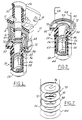
- a fuel injector 10 is shown broken away to reveal internal details.
- the injector 10 is a typical design and illustrative of the type with which the internal heater according to the present invention can be used.
- An upper "power group” 12 subassembly includes a molded outer housing 14 enclosing a solenoid operator 16.
- An integral molded connector body 18 encapsulated contacts and conductors used to direct electrical power to the solenoid 16 in the well known manner.
- An upper housing portion 20 is adapted to be received in a pocket in a fuel rail 23 so as to communicate fuel under pressure to the interior of the injector 10, an O-ring seal 22 sealing the connection.
- valve group 24 comprises a lower subassembly mounted to the power group 12 at final assembly, which includes a generally cylindrical valve body 26 having an injector end cap element 28 press fit and welded to its lower end.
- an O-ring 42 for sealing the injector 10 in the bore in the intake manifold.
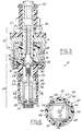
- a valve seat 30 ( Figures 3 and 5) is mounted in the tip or injector end cap 28, having a surface adapted to mate with the tip of an elongated needle valve element 32.
- Valve element 32 is swaged to an armature 34 which is drawn against the lower end face of an inlet tube 36 when the solenoid is energized, lifting the tip end of the valve element off the valve seat 30 to allow to flow out of the injector in the well known manner.
- a spring 38 is compressed between the armature 34 and an adjusting tube 37 to normally hold the valve element 32 in its seated position.
- the injector lower end is received in a mating bore in an intake manifold (or cylinder head) (not shown) which receives the fuel sprayed out when the injector valve element 32 is opened.
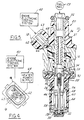
- the timing and duration of the opening is controlled by electrical signals received from an engine electronic control system 40 ( Figure 4).
- an internal heater 44 is contained within the valve group 24 just upstream of the valve seat 30, thereby positioned immediately adjacent the point of exit of the fuel.
- the heater 44 is comprised of four rectangular plates 46 of a positive temperature coefficient (PTC) material lengthwise arrayed and about the axis of the valve element 32, contained within the valve body 26.
- the array of PTC plates 46 loosely form a square tube 47 shape confined within the circular bore 48 of the valve body 26 ( Figure 6).
- the square tube shape creates intervening spaces 54, and hence fuel entering the bore 50 after passing through the armature 34 flows through spaces 54, as well as central portion 52 of the tube 47 so that fuel comes into contact with both sides of each PTC plate 46.
- the increased diameter of bore 48 increases the residence time of the fuel in contact with the PTC plates 46 to enhance the transfer of heat into the fuel immediately prior to injection.
- An inner conductor track band 56 and outer conductor track band 58 respectively encircle the inner and outer perimeter of the square tube shape, each band 56, 58 electrically and mechanically connected to a respective end of each PTC plate 46 by a suitable electrically conductive adhesive.
- a sleeve 60 of fuel resistant insulating material such as TeflonTM is installed in the valve body bore 48.
- the PTC plates and bands 56, 58 are preferably completely coated with a thin layer (of the order of 25.4 ⁇ m (0.001 in) thickness) of a fuel impervious coating, such as KaptonTM, a material available from DuPont.
- a fuel impervious coating such as KaptonTM, a material available from DuPont.
- KaptonTM a material available from DuPont.
- a heat conductive formulation of KaptonTM aiding heat transfer is preferred.
- Other suitable coatings may be employed, although the use of a coating may not be necessary.
- the PTC plates 46 are supplied with electrical power via the bands 56, 58 which in turn are supplied by connections to contacts 62 in the connector body 18 ( Figure 4), enabling connection to a heater power supply 64.
- An internal connection system extends from the contacts 62, 63 to the inner band track 56 and outer band track 58, including embedded wires 66, 68 extending to spring-loaded pins 70, 72 disposed in housing 14 outwardly of the solenoid 16.
- An annular conductive split disc 76 coated with KaptonTM is positioned abutting against an upper end of the valve body 26.
- a pair of conductive tracks 78, 80 are formed by exposed arcuate areas on each respective segment 82, 84 of the split disc 76, each engaged by a tip of a spring loaded pin 70, 72.
- Each split disc segment 82, 84 has a downwardly extending tab 86, 88 ( Figure 5) soldered or adhesively attached to a respective track band 56, 68 to complete the circuit.
- valve body 26 allows angling of the tabs 86, 88 inwardly to the bands 56, 58.
- An O-ring seal 90 engages the surface of the split disc 76 inside the exposed tracks 78, 80 to prevent fuel contact therewith.
- split disc 76 a pair of conductive annular discs 92, 94 can be used separated and covered by KaptonTM coating layers 96, 98, 100 having suitable cutouts to enable contact of the pins 70, 72 ( Figure 7).
- spring-loaded pins 70, 72 allows easy assembly of the power group 12 to the valve group 24.
- electrical conductors extending internally within the injector or externally outside of the injector to the bands 56, 58 can be employed.
- the PTC material for plates 46 can be selected to be self-limiting at a temperature which will heat the fuel to a desired temperature level, such as 80°C. This technology is itself well known and hence details thereof are not here set forth.
- the arrangement described allows efficient heat transfer into the fuel at a point close to that point whereat the fuel is injected.
Landscapes
- Engineering & Computer Science (AREA)
- Chemical & Material Sciences (AREA)
- Combustion & Propulsion (AREA)
- Mechanical Engineering (AREA)
- General Engineering & Computer Science (AREA)
- Physics & Mathematics (AREA)
- Electromagnetism (AREA)
- Fuel-Injection Apparatus (AREA)
Description
Claims (9)
- A fuel injector (10) for an internal combustion engine including:characterised in that said PTC structure comprises an array of rectangular plates (46) mounted within said internal bore (48) of said valve body (26), said plates being arranged lengthwise to form a generally square tube shape (47) about said valve element (30) so that fuel flows through spaces (52, 54) on front and back surfaces of each PTC plate (46), said PTC structure having first and second conductive tracks (56, 58) formed thereon for engagement with said connector means (66, 68, 70, 72, 76, 78, 80, 82, 84, 86, 88), said first and second tracks (56, 58) being spaced from one another;a generally cylindrical valve body (26) having an internal bore (48);a valve seat (30) mounted to a tip end of said valve body (26);an elongate needle valve element (32) having a tip end engageable with said valve seat (30);operating means (16, 34) for operating said valve element (32) to unseat it from said valve seat (30) to enable outflow of fuel;a fuel heater (44, 46, 47) comprises of a structure of positive temperature coefficient (PTC) material;a heater power supply (64); andconnector means (66, 68, 70, 72, 76, 78, 80, 82, 84, 86, 88) for connecting said heater power supply (64) to said fuel heater (44, 46, 47);
and in that said operating means (16, 34) comprises a solenoid operator (16) and an armature (34) attached to an end of said valve element (32) opposite to said tip end. - The fuel injector according to claim 1, wherein said first and second tracks (56, 58) comprise bands extending about the perimeter of said PTC plates (46) and arranged in a general square tube shape.
- The fuel injector according to claim 1 or 2 wherein said PTC plates (46) are coated to be fuel impervious.
- The fuel injector according to any one of claims 1 to 3 wherein a heat insulating sleeve (60) is mounted within said valve body (26) surrounding said PTC structure.
- The fuel injector according to claim 4 wherein said sleeve (60) is constructed of Teflon™.
- The fuel injector according to any one of claims 1 to 5 wherein said connector means (66, 68, 70, 72, 76, 78, 80, 82, 84, 86, 88) includes an annular conductive disc (76; 92, 94, 96, 98, 100) mounted in said injector abutting an upper end of said valve body (26), an O-ring seal (90) engaged against an upper face of said disc (76; 92, 94, 96, 98, 100), electrical connections (70, 72) to an outer perimeter of said disc (76; 92, 94, 96, 98, 100), and tabs (86, 88) integral with an inner diameter of said disc (76; 92, 94, 96, 98, 100) connected to said first and second tracks (56, 58) respectively.
- The fuel injector according to claim 6 wherein said electrical connections (70, 72) to said outer perimeter of said disc (76; 92, 94, 96, 98, 100) comprise spring-loaded contact pins.
- The fuel injector according to claim 6 or 7 wherein said annular disc (76) is split to provide separate electrical paths.
- The fuel injector according to claim 6 or 7 wherein said annular disc (92, 94, 96, 98, 100) is comprised of a pair of separate disc elements (92, 94) stacked together with an interposed layer of electrically insulating material (98), and having an outer coating (96, 100) of electrically insulating material thereon.
Applications Claiming Priority (3)
| Application Number | Priority Date | Filing Date | Title |
|---|---|---|---|
| US08/627,707 US5758826A (en) | 1996-03-29 | 1996-03-29 | Fuel injector with internal heater |
| US627707 | 1996-03-29 | ||
| PCT/US1997/004677 WO1997037121A1 (en) | 1996-03-29 | 1997-03-21 | Fuel injector with internal heater |
Publications (2)
| Publication Number | Publication Date |
|---|---|
| EP0890023A1 EP0890023A1 (en) | 1999-01-13 |
| EP0890023B1 true EP0890023B1 (en) | 2002-02-06 |
Family
ID=24515790
Family Applications (1)
| Application Number | Title | Priority Date | Filing Date |
|---|---|---|---|
| EP97916927A Expired - Lifetime EP0890023B1 (en) | 1996-03-29 | 1997-03-21 | Fuel injector with internal heater |
Country Status (6)
| Country | Link |
|---|---|
| US (1) | US5758826A (en) |
| EP (1) | EP0890023B1 (en) |
| JP (1) | JP3357072B2 (en) |
| KR (1) | KR100329157B1 (en) |
| DE (1) | DE69710318T2 (en) |
| WO (1) | WO1997037121A1 (en) |
Cited By (1)
| Publication number | Priority date | Publication date | Assignee | Title |
|---|---|---|---|---|
| DE10351206B4 (en) * | 2003-11-03 | 2016-12-22 | Robert Bosch Gmbh | Injector |
Families Citing this family (64)
| Publication number | Priority date | Publication date | Assignee | Title |
|---|---|---|---|---|
| US6109543A (en) * | 1996-03-29 | 2000-08-29 | Siemens Automotive Corporation | Method of preheating fuel with an internal heater |
| US6102303A (en) * | 1996-03-29 | 2000-08-15 | Siemens Automotive Corporation | Fuel injector with internal heater |
| US6047907A (en) * | 1997-12-23 | 2000-04-11 | Siemens Automotive Corporation | Ball valve fuel injector |
| US6422481B2 (en) | 1998-06-01 | 2002-07-23 | Siemens Automotive Corporation | Method of enhancing heat transfer in a heated tip fuel injector |
| US6135360A (en) * | 1998-06-01 | 2000-10-24 | Siemens Automotive Corporation | Heated tip fuel injector with enhanced heat transfer |
| DE19827136A1 (en) * | 1998-06-18 | 1999-12-23 | Bosch Gmbh Robert | Fuel injector |
| DE19843317B4 (en) * | 1998-09-22 | 2009-06-25 | GM Global Technology Operations, Inc., Detroit | Heated injection valve for spark-ignited internal combustion engines |
| US6332457B1 (en) | 1999-02-26 | 2001-12-25 | Siemens Automotive Corporation | Method of using an internally heated tip injector to reduce hydrocarbon emissions during cold-start |
| US6769421B2 (en) * | 1999-08-24 | 2004-08-03 | Randolph M. Pentel | Method and apparatus for vaporizing fuel |
| HK1048273A1 (en) | 1999-09-22 | 2003-03-28 | Ngimat Co. | Liquid atomization methods and devices |
| US6616066B2 (en) | 2000-01-29 | 2003-09-09 | Daimlerchrysler Ag | Injection valve |
| DE10053583B4 (en) * | 2000-01-29 | 2004-11-25 | Daimlerchrysler Ag | Injector |
| JP4092526B2 (en) * | 2000-06-19 | 2008-05-28 | 株式会社デンソー | Fuel injection device |
| JP4587156B2 (en) * | 2000-08-21 | 2010-11-24 | ボルボ ラストバグナー アーベー | Needle position detector |
| DE10060289A1 (en) * | 2000-12-05 | 2002-06-06 | Bosch Gmbh Robert | Fuel injector |
| US6811091B2 (en) * | 2000-12-29 | 2004-11-02 | Siemens Automotive Corporation | Modular fuel injector having an integral filter and dynamic adjustment assembly |
| US6561168B2 (en) * | 2001-03-29 | 2003-05-13 | Denso Corporation | Fuel injection device having heater |
| JP2002295333A (en) * | 2001-03-30 | 2002-10-09 | Denso Corp | Fuel injection device |
| US6688533B2 (en) | 2001-06-29 | 2004-02-10 | Siemens Vdo Automotive Corporation | Apparatus and method of control for a heated tip fuel injector |
| CA2457912C (en) * | 2001-08-30 | 2011-09-20 | Cooper Technology Services, Llc. | Heated pcv valve and hose assemblies |
| US7552715B1 (en) * | 2002-03-15 | 2009-06-30 | Jeremy Holmes | Universal injection valve assembly |
| US6928992B1 (en) * | 2002-03-15 | 2005-08-16 | Jeremy Holmes | Universal injection valve assembly |
| US6820598B2 (en) | 2002-03-22 | 2004-11-23 | Chrysalis Technologies Incorporated | Capillary fuel injector with metering valve for an internal combustion engine |
| US6913005B2 (en) | 2002-03-22 | 2005-07-05 | Chrysalis Technologies Incorporated | System and methodology for purging fuel from a fuel injector during start-up |
| US6779513B2 (en) | 2002-03-22 | 2004-08-24 | Chrysalis Technologies Incorporated | Fuel injector for an internal combustion engine |
| US6913004B2 (en) * | 2002-03-22 | 2005-07-05 | Chrysalis Technologies Incorporated | Fuel system for an internal combustion engine and method for controlling same |
| US7249596B2 (en) * | 2002-03-22 | 2007-07-31 | Philip Morris Usa Inc. | Fuel system for an internal combustion engine and method for controlling same |
| US7357124B2 (en) | 2002-05-10 | 2008-04-15 | Philip Morris Usa Inc. | Multiple capillary fuel injector for an internal combustion engine |
| US7032576B2 (en) | 2002-05-10 | 2006-04-25 | Philip Morris Usa Inc. | Capillary heating control and fault detection system and methodology for fuel system in an internal combustion engine |
| JP2005538311A (en) * | 2002-09-11 | 2005-12-15 | ベイポレイト・プロプライエタリー・リミテッド | Fuel supply system |
| JP2004339946A (en) * | 2003-05-13 | 2004-12-02 | Nippon Soken Inc | Fuel injection valve |
| US7017547B2 (en) * | 2003-06-09 | 2006-03-28 | Southwest Res Inst | Method and apparatus for controlling liquid-phase fuel penetration distance in a direct-fuel injected engine |
| JP4118216B2 (en) * | 2003-10-07 | 2008-07-16 | 株式会社デンソー | Fuel injection device |
| DE602004030630D1 (en) | 2003-10-30 | 2011-01-27 | Philip Morris Usa Inc | Multi-capillary fuel injector for an internal combustion engine |
| DE10355039B4 (en) * | 2003-11-25 | 2017-09-14 | Robert Bosch Gmbh | Fuel injection valve |
| US7337768B2 (en) | 2004-05-07 | 2008-03-04 | Philip Morris Usa Inc. | Multiple capillary fuel injector for an internal combustion engine |
| JP2006183657A (en) * | 2004-12-02 | 2006-07-13 | Nissan Motor Co Ltd | Injector |
| US8261575B1 (en) | 2005-01-18 | 2012-09-11 | Jeremy Holmes | Self cooling motor system |
| US7766251B2 (en) * | 2005-12-22 | 2010-08-03 | Delavan Inc | Fuel injection and mixing systems and methods of using the same |
| US7481376B2 (en) * | 2006-03-17 | 2009-01-27 | Continental Automotive Systems Us, Inc. | Variable inductive heated injector |
| US8967124B2 (en) * | 2006-03-21 | 2015-03-03 | Continental Automotive Systems, Inc. | Inductive heated injector using voltage transformer technology |
| US20070235086A1 (en) * | 2006-03-21 | 2007-10-11 | Siemens Vdo Automotive Corporation | Fuel injector with inductive heater |
| US8695901B2 (en) * | 2006-03-22 | 2014-04-15 | Continental Automotive Systems, Inc. | Inductive heated injector using a three wire connection |
| US20070221747A1 (en) * | 2006-03-22 | 2007-09-27 | Siemens Vdo Automotive Corporation | Super imposed signal for an actuator and heater of a fuel injector |
| US7677468B2 (en) * | 2006-03-27 | 2010-03-16 | Continental Automotive Systems Us, Inc. | Inductive heated injector using additional coil |
| US20070235569A1 (en) * | 2006-03-28 | 2007-10-11 | Siemens Vdo Automotive Corporation | Coil For Actuating and Heating Fuel Injector |
| US20080060621A1 (en) * | 2006-09-13 | 2008-03-13 | Trapasso David J | Heated fuel injector for cold starting of ethanol-fueled engines |
| DE102006058881A1 (en) * | 2006-12-13 | 2008-06-19 | Siemens Ag | Nozzle assembly for an injection valve and injection valve |
| EP2137399B1 (en) * | 2007-03-16 | 2017-05-10 | Continental Automotive Systems, Inc. | Fuel injection system |
| US8281570B2 (en) * | 2007-08-09 | 2012-10-09 | Caterpillar Inc. | Reducing agent injector having purge heater |
| DE102007049973A1 (en) * | 2007-10-18 | 2009-04-23 | Robert Bosch Gmbh | Heating device for liquid fuels and the like |
| GB2454022A (en) * | 2007-10-27 | 2009-04-29 | Uav Engines Ltd | Fuel heating apparatus to aid cold starts in low ambient temperatures |
| US7735460B2 (en) * | 2008-02-01 | 2010-06-15 | Leonard Bloom | Method and apparatus for operating standard gasoline-driven engines with a readily-available non-volatile fuel, thereby obviating the use of gasoline |
| US20110168144A1 (en) * | 2008-08-22 | 2011-07-14 | Leonard Bloom | Method and apparatus for operating standard gasoline-driven engines with a readily-available non-volatile fuel, thereby obviating the use of gasoline |
| US20100078507A1 (en) * | 2008-09-29 | 2010-04-01 | Short Jason C | Heated and insulated fuel injector |
| US8342425B2 (en) * | 2008-12-03 | 2013-01-01 | Continental Automotive Systems Us, Inc. | Multi-point low pressure inductively heated fuel injector with heat exchanger |
| US8439018B2 (en) * | 2010-05-04 | 2013-05-14 | Delphi Technologies, Inc. | Heated fuel injector system |
| DE102012220429A1 (en) | 2012-11-09 | 2014-05-15 | Mahle International Gmbh | Preheating device for a fuel injection system |
| DE102013102219B4 (en) * | 2013-03-06 | 2020-08-06 | Dr. Ing. H.C. F. Porsche Aktiengesellschaft | Heated injector for fuel injection in an internal combustion engine |
| US9476393B2 (en) | 2013-03-19 | 2016-10-25 | Delphi Technologies, Inc. | Heated fuel injector |
| JP2015059457A (en) * | 2013-09-18 | 2015-03-30 | 日立オートモティブシステムズ株式会社 | Fuel injection valve |
| CN105464866A (en) * | 2016-01-14 | 2016-04-06 | 吉林大学 | Gasoline direct injection (GDI) oil sprayer for utilizing electromagnetic heating coil for heating |
| BR102016018530A8 (en) * | 2016-08-12 | 2018-06-26 | Mahle Int Gmbh | fuel heater assembly and fuel supply and heating system |
| WO2020164695A1 (en) * | 2019-02-13 | 2020-08-20 | Pierburg Gmbh | Valve device |
Family Cites Families (21)
| Publication number | Priority date | Publication date | Assignee | Title |
|---|---|---|---|---|
| DE2210250C2 (en) * | 1972-03-03 | 1982-05-13 | Robert Bosch Gmbh, 7000 Stuttgart | Fuel injection device for cold starting and warming up externally ignited internal combustion engines |
| JPS5148815B2 (en) * | 1973-03-09 | 1976-12-23 | ||
| US3876861A (en) * | 1974-10-03 | 1975-04-08 | John W Wightman | Heating unit |
| JPS604557B2 (en) * | 1975-09-03 | 1985-02-05 | 日本碍子株式会社 | Barium titanate-based positive characteristic porcelain heating element with numerous through holes |
| US4279234A (en) * | 1979-01-12 | 1981-07-21 | Texas Instruments Incorporated | Early fuel evaporation of carburetion system |
| EP0017057B1 (en) * | 1979-03-27 | 1982-03-10 | Danfoss A/S | Fuel oil preheating device |
| DE3327773A1 (en) * | 1983-05-13 | 1984-11-15 | Robert Bosch Gmbh, 7000 Stuttgart | FUEL INJECTION DEVICE IN COMBUSTION CHAMBER |
| US4458655A (en) * | 1983-06-27 | 1984-07-10 | General Motors Corporation | Fuel injection nozzle with heated valve |
| DE3414201A1 (en) * | 1984-04-14 | 1985-10-17 | Robert Bosch Gmbh, 7000 Stuttgart | DEVICE FOR INJECTING FUEL IN COMBUSTION ROOMS |
| US4633069A (en) * | 1985-10-21 | 1986-12-30 | Texas Instruments Incorporated | Heat-exchanger |
| US4713524A (en) * | 1986-04-21 | 1987-12-15 | Gte Products Corporation | PTC fuel heater for heating alcohol fuel |
| DE3617353A1 (en) * | 1986-05-23 | 1987-11-26 | Bosch Gmbh Robert | FUEL INJECTION NOZZLE FOR INTERNAL COMBUSTION ENGINES |
| NL8601384A (en) * | 1986-05-29 | 1987-12-16 | Texas Instruments Holland | COMBUSTION ENGINE WITH FUEL INJECTION SYSTEM AND AN INJECTION VALVE INTENDED FOR SUCH AN ENGINE. |
| US4870249A (en) * | 1987-05-26 | 1989-09-26 | Texas Instruments Incorporated | Electric fuel heating device |
| US5218943A (en) * | 1991-01-07 | 1993-06-15 | Toyota Jidosha Kabushiki Kaisha | Fuel injection apparatus for internal combustion engine |
| US5389195A (en) * | 1991-03-07 | 1995-02-14 | Minnesota Mining And Manufacturing Company | Surface modification by accelerated plasma or ions |
| JPH04350360A (en) * | 1991-04-24 | 1992-12-04 | Aisan Ind Co Ltd | Atomized fuel heating device |
| US5401935A (en) * | 1993-05-28 | 1995-03-28 | Heaters Engineering, Inc. | Fuel heating assembly |
| US5400969A (en) * | 1993-09-20 | 1995-03-28 | Keene; Christopher M. | Liquid vaporizer and diffuser |
| ES2100753T3 (en) * | 1994-04-12 | 1997-06-16 | Ulev Gmbh | DEVICE FOR FUEL NEBULIZATION. |
| DE19542317A1 (en) | 1995-11-14 | 1997-05-15 | Bosch Gmbh Robert | Fuel injection device for an internal combustion engine |
-
1996
- 1996-03-29 US US08/627,707 patent/US5758826A/en not_active Expired - Fee Related
-
1997
- 1997-03-21 KR KR1019980707764A patent/KR100329157B1/en not_active Expired - Fee Related
- 1997-03-21 JP JP53533997A patent/JP3357072B2/en not_active Expired - Fee Related
- 1997-03-21 WO PCT/US1997/004677 patent/WO1997037121A1/en not_active Ceased
- 1997-03-21 EP EP97916927A patent/EP0890023B1/en not_active Expired - Lifetime
- 1997-03-21 DE DE69710318T patent/DE69710318T2/en not_active Expired - Fee Related
Cited By (1)
| Publication number | Priority date | Publication date | Assignee | Title |
|---|---|---|---|---|
| DE10351206B4 (en) * | 2003-11-03 | 2016-12-22 | Robert Bosch Gmbh | Injector |
Also Published As
| Publication number | Publication date |
|---|---|
| KR100329157B1 (en) | 2002-09-17 |
| US5758826A (en) | 1998-06-02 |
| JP3357072B2 (en) | 2002-12-16 |
| JP2000507663A (en) | 2000-06-20 |
| DE69710318T2 (en) | 2002-08-22 |
| WO1997037121A1 (en) | 1997-10-09 |
| DE69710318D1 (en) | 2002-03-21 |
| KR20000005122A (en) | 2000-01-25 |
| EP0890023A1 (en) | 1999-01-13 |
Similar Documents
| Publication | Publication Date | Title |
|---|---|---|
| US5758826A (en) | Fuel injector with internal heater | |
| JP2711365B2 (en) | Vaporization injector | |
| US6102303A (en) | Fuel injector with internal heater | |
| EP0927301B1 (en) | Method of preheating fuel with an internal heater | |
| US6578775B2 (en) | Fuel injector | |
| US7263984B2 (en) | Heated PCV valve and hose assemblies | |
| EP0343652B1 (en) | Internal combustion engine of the injection type, and plate intended for fitting between the inlet ports of a cylinder block of such an engine and an inlet tube | |
| US5143039A (en) | Fuel distributor for the fuel injection sytems of internal combustion engines | |
| US5609297A (en) | Fuel atomization device | |
| MXPA05002769A (en) | Fuel delivery system. | |
| US5690080A (en) | Fuel heater for heating liquid fuel under pressure for an internal injection engine | |
| US7387263B2 (en) | Fuel injection valve of engine, fuel injection method and assembling method of the same | |
| US5746168A (en) | Cylinder head cover of an internal combustion engine | |
| US6752333B2 (en) | Fuel injection valve | |
| CA1230937A (en) | Glow plug having a resistive surface film heater | |
| US6465759B1 (en) | Ion sensor glow plug assembly | |
| US20030118962A1 (en) | Fuel duct for supplying fuel to a combustion chamber | |
| JPH04350360A (en) | Atomized fuel heating device | |
| US6848634B1 (en) | Fuel injector with thermally isolated seat | |
| JP3584573B2 (en) | Spark ignition internal combustion engine | |
| JP3888177B2 (en) | Fuel injection valve | |
| JP2841951B2 (en) | Fuel injection device for internal combustion engine | |
| JPS59170460A (en) | Fuel heating device for internal combustion engine | |
| JPS62261666A (en) | Fuel injector for injecting fuel to combustion chamber for internal combustion engine | |
| JPH06229349A (en) | Fuel supply device for internal combustion engine |
Legal Events
| Date | Code | Title | Description |
|---|---|---|---|
| PUAI | Public reference made under article 153(3) epc to a published international application that has entered the european phase |
Free format text: ORIGINAL CODE: 0009012 |
|
| 17P | Request for examination filed |
Effective date: 19980925 |
|
| AK | Designated contracting states |
Kind code of ref document: A1 Designated state(s): DE FR GB IT |
|
| GRAG | Despatch of communication of intention to grant |
Free format text: ORIGINAL CODE: EPIDOS AGRA |
|
| 17Q | First examination report despatched |
Effective date: 20010409 |
|
| GRAG | Despatch of communication of intention to grant |
Free format text: ORIGINAL CODE: EPIDOS AGRA |
|
| GRAH | Despatch of communication of intention to grant a patent |
Free format text: ORIGINAL CODE: EPIDOS IGRA |
|
| GRAH | Despatch of communication of intention to grant a patent |
Free format text: ORIGINAL CODE: EPIDOS IGRA |
|
| GRAA | (expected) grant |
Free format text: ORIGINAL CODE: 0009210 |
|
| REG | Reference to a national code |
Ref country code: GB Ref legal event code: IF02 |
|
| AK | Designated contracting states |
Kind code of ref document: B1 Designated state(s): DE FR GB IT |
|
| REF | Corresponds to: |
Ref document number: 69710318 Country of ref document: DE Date of ref document: 20020321 |
|
| ET | Fr: translation filed | ||
| PLBE | No opposition filed within time limit |
Free format text: ORIGINAL CODE: 0009261 |
|
| STAA | Information on the status of an ep patent application or granted ep patent |
Free format text: STATUS: NO OPPOSITION FILED WITHIN TIME LIMIT |
|
| 26N | No opposition filed |
Effective date: 20021107 |
|
| PGFP | Annual fee paid to national office [announced via postgrant information from national office to epo] |
Ref country code: GB Payment date: 20070313 Year of fee payment: 11 |
|
| PGFP | Annual fee paid to national office [announced via postgrant information from national office to epo] |
Ref country code: FR Payment date: 20070320 Year of fee payment: 11 |
|
| GBPC | Gb: european patent ceased through non-payment of renewal fee |
Effective date: 20080321 |
|
| REG | Reference to a national code |
Ref country code: FR Ref legal event code: ST Effective date: 20081125 |
|
| PG25 | Lapsed in a contracting state [announced via postgrant information from national office to epo] |
Ref country code: FR Free format text: LAPSE BECAUSE OF NON-PAYMENT OF DUE FEES Effective date: 20080331 |
|
| PG25 | Lapsed in a contracting state [announced via postgrant information from national office to epo] |
Ref country code: GB Free format text: LAPSE BECAUSE OF NON-PAYMENT OF DUE FEES Effective date: 20080321 |
|
| PGFP | Annual fee paid to national office [announced via postgrant information from national office to epo] |
Ref country code: IT Payment date: 20090324 Year of fee payment: 13 Ref country code: DE Payment date: 20090320 Year of fee payment: 13 |
|
| PG25 | Lapsed in a contracting state [announced via postgrant information from national office to epo] |
Ref country code: DE Free format text: LAPSE BECAUSE OF NON-PAYMENT OF DUE FEES Effective date: 20101001 |
|
| PG25 | Lapsed in a contracting state [announced via postgrant information from national office to epo] |
Ref country code: IT Free format text: LAPSE BECAUSE OF NON-PAYMENT OF DUE FEES Effective date: 20100321 |