EP0889544B1 - Elektrische Kontaktierung von Feinstdrähten, mit einem Nenndurchmesser von 100 Mikrometer oder weniger - Google Patents
Elektrische Kontaktierung von Feinstdrähten, mit einem Nenndurchmesser von 100 Mikrometer oder weniger Download PDFInfo
- Publication number
- EP0889544B1 EP0889544B1 EP98109731A EP98109731A EP0889544B1 EP 0889544 B1 EP0889544 B1 EP 0889544B1 EP 98109731 A EP98109731 A EP 98109731A EP 98109731 A EP98109731 A EP 98109731A EP 0889544 B1 EP0889544 B1 EP 0889544B1
- Authority
- EP
- European Patent Office
- Prior art keywords
- wire
- plates
- clamping area
- contact
- contacting
- Prior art date
- Legal status (The legal status is an assumption and is not a legal conclusion. Google has not performed a legal analysis and makes no representation as to the accuracy of the status listed.)
- Expired - Lifetime
Links
- 238000004519 manufacturing process Methods 0.000 claims description 5
- 238000003466 welding Methods 0.000 claims description 4
- 238000004026 adhesive bonding Methods 0.000 claims description 2
- 238000000034 method Methods 0.000 claims 2
- 239000000463 material Substances 0.000 abstract description 5
- 238000003892 spreading Methods 0.000 description 5
- 239000012528 membrane Substances 0.000 description 3
- 239000002966 varnish Substances 0.000 description 3
- 229910016347 CuSn Inorganic materials 0.000 description 2
- PXHVJJICTQNCMI-UHFFFAOYSA-N Nickel Chemical compound [Ni] PXHVJJICTQNCMI-UHFFFAOYSA-N 0.000 description 2
- 229910052782 aluminium Inorganic materials 0.000 description 2
- XAGFODPZIPBFFR-UHFFFAOYSA-N aluminium Chemical compound [Al] XAGFODPZIPBFFR-UHFFFAOYSA-N 0.000 description 2
- 238000009413 insulation Methods 0.000 description 2
- BQCADISMDOOEFD-UHFFFAOYSA-N Silver Chemical compound [Ag] BQCADISMDOOEFD-UHFFFAOYSA-N 0.000 description 1
- 239000004020 conductor Substances 0.000 description 1
- 238000011161 development Methods 0.000 description 1
- 230000018109 developmental process Effects 0.000 description 1
- 230000005520 electrodynamics Effects 0.000 description 1
- PCHJSUWPFVWCPO-UHFFFAOYSA-N gold Chemical compound [Au] PCHJSUWPFVWCPO-UHFFFAOYSA-N 0.000 description 1
- 229910052737 gold Inorganic materials 0.000 description 1
- 239000010931 gold Substances 0.000 description 1
- 239000004922 lacquer Substances 0.000 description 1
- 229910052751 metal Inorganic materials 0.000 description 1
- 239000002184 metal Substances 0.000 description 1
- 229910052759 nickel Inorganic materials 0.000 description 1
- 229910052709 silver Inorganic materials 0.000 description 1
- 239000004332 silver Substances 0.000 description 1
- 230000007704 transition Effects 0.000 description 1
Images

Classifications
-
- H—ELECTRICITY
- H01—ELECTRIC ELEMENTS
- H01R—ELECTRICALLY-CONDUCTIVE CONNECTIONS; STRUCTURAL ASSOCIATIONS OF A PLURALITY OF MUTUALLY-INSULATED ELECTRICAL CONNECTING ELEMENTS; COUPLING DEVICES; CURRENT COLLECTORS
- H01R4/00—Electrically-conductive connections between two or more conductive members in direct contact, i.e. touching one another; Means for effecting or maintaining such contact; Electrically-conductive connections having two or more spaced connecting locations for conductors and using contact members penetrating insulation
- H01R4/28—Clamped connections, spring connections
- H01R4/48—Clamped connections, spring connections utilising a spring, clip, or other resilient member
-
- H—ELECTRICITY
- H01—ELECTRIC ELEMENTS
- H01R—ELECTRICALLY-CONDUCTIVE CONNECTIONS; STRUCTURAL ASSOCIATIONS OF A PLURALITY OF MUTUALLY-INSULATED ELECTRICAL CONNECTING ELEMENTS; COUPLING DEVICES; CURRENT COLLECTORS
- H01R4/00—Electrically-conductive connections between two or more conductive members in direct contact, i.e. touching one another; Means for effecting or maintaining such contact; Electrically-conductive connections having two or more spaced connecting locations for conductors and using contact members penetrating insulation
- H01R4/24—Connections using contact members penetrating or cutting insulation or cable strands
- H01R4/2495—Insulation penetration combined with permanent deformation of the contact member, e.g. crimping
-
- H—ELECTRICITY
- H01—ELECTRIC ELEMENTS
- H01R—ELECTRICALLY-CONDUCTIVE CONNECTIONS; STRUCTURAL ASSOCIATIONS OF A PLURALITY OF MUTUALLY-INSULATED ELECTRICAL CONNECTING ELEMENTS; COUPLING DEVICES; CURRENT COLLECTORS
- H01R4/00—Electrically-conductive connections between two or more conductive members in direct contact, i.e. touching one another; Means for effecting or maintaining such contact; Electrically-conductive connections having two or more spaced connecting locations for conductors and using contact members penetrating insulation
- H01R4/02—Soldered or welded connections
- H01R4/023—Soldered or welded connections between cables or wires and terminals
Definitions
- wire thickness of the Wires to the electro-acoustic transducer are often smaller than 100 ⁇ m and, moreover, often aluminum as a wire material is used, which is not always reliable with such wire thicknesses and can be easily connected to a contact socket.
- electrical contacting is used to achieve the object with the features of claims 1 and 10 proposed.
- the invention electrical contacting of the fine wire which has a nominal diameter of 100 ⁇ m or less consists of a contact socket with two opposite plates, in which a plate clamping area is provided, in which the plate spacing is smaller than in the other plate areas and in Clamping area, the wire is clamped between the plates and with at least one of the plates is electrically connected.
- Advantageous further training are described in the subclaims.
- an electro-acoustic transducer with a contact with the above Features described as well as an electrical device with a such electro-acoustic transducer and a method for producing the electrical contacting of the fine wire.
- the contacting or by the inventive method for producing this contact Connection is established, which is mechanically sufficiently firm and electrical is very good conductor.
- the contacting according to the invention also means that Wire in the clamping area is automatically protected because the opposite one Cover the wire of the contact socket in the clamping area.
- the contact is stabilized when the plates are together in the clamping area be connected, e.g. by applying a spot weld from the outside.
- Such welding automatically turns any insulation or baking varnish on the wire in the clamping area even more effectively than by the clamping itself on the side displaced and the displaced lacquer then seals the contact area.
- the wire By clamping the wire in the clamping area, the wire is through the Clamping force deformed so that there is a spreading of the wire in the clamping area established. As a result, the surface of the wire and thus the contact area becomes closed the plates enlarged.
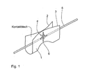
- Fig. 1 shows a perspective view of a contact socket, which as a U-shaped Contact plate 1 with two substantially opposite plate legs 2 and 3 is formed.
- a contact socket which as a U-shaped Contact plate 1 with two substantially opposite plate legs 2 and 3 is formed.
- In the middle area 4 of the two opposite Plates 2 and 3 are smaller by clamping from the outside Spaced apart than in the plate areas outside of the clamped Range.
- Within the contact socket between the opposite plates a fine wire 5 is arranged in the longitudinal direction of the contact socket and in Clamping area 4 clamped between the plates 2 and 3 of the contact socket.
- the fine wire 5 undergoes deformation, preferably one Spreading so that the fine wire has a larger outer surface in the clamping area has as outside the clamping range.
- the Fine wire in the clamping area is also baked and / or insulating varnish, which surrounds the wire pushed to the edge area of the sheet-wire contact, so that the sheet-wire contact through the insulation and / or baking varnish after is protected on the outside.
- Fig. 1 shows a plan view of an elongated weld 6, which runs essentially perpendicular to the wire 5.
- Fig. 2 shows the top view of the contact plate 1.
- the plate areas also protect outside the clamping area there the wire, so that even if the wire is arranged differently from the wire longitudinal direction shown no wire tear through a kink fear.
- the spreading angle between the opposite plates should be between 1 ° and 30 °, but it is also a larger radius conceivable, as indicated by the dashed line in Fig. 2.
- the pull-out forces that are required can be small enough angles to pull the wire out of the contact plate, greater than the tensile strength of the wire itself.
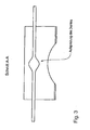
- Fig. 3 shows a section along the line A-A in Fig. 2. Here is particularly good the spreading of the wire in the clamping area can be seen. By spreading of the wire, the contact surface between wire and sheet is increased so that unwanted transition resistances cannot arise at all.
- Any conventional wire material, in particular aluminum or CuSn can be used.
- a CuSn material can also be used as the contact material be used, which is provided with a nickel, silver or gold layer is.
Landscapes
- Connections Effected By Soldering, Adhesion, Or Permanent Deformation (AREA)
- Non-Insulated Conductors (AREA)
- Coupling Device And Connection With Printed Circuit (AREA)
- Connections By Means Of Piercing Elements, Nuts, Or Screws (AREA)
- Multi-Conductor Connections (AREA)
- Audible-Bandwidth Dynamoelectric Transducers Other Than Pickups (AREA)
Description
- Fig. 1
- eine perspektivische Aufsicht auf eine erfindungsgemäße Kontaktierung eines Drahtes und einer Kontaktbuchse;
- Fig. 2
- eine Aufsicht von oben auf die Kontaktierung nach Fig. 1;
- Fig. 3
- einen Schnitt gemäß der Ebene A-A in Fig. 3;
Claims (11)
- Elektrische Kontaktierung eines Drahtes mit einem Nenndurchmesser von etwa 100 µm oder weniger mit:einem Kontaktblech (1) mit zwei gegenüberliegenden Platten (2, 3);einem Platten-Klemmbereich (4), in dem der Plattenabstand geringer ist als in den anderen Plattenbereichen; undim Klemmbereich (4) ist der Draht zwischen den Platten (2, 3) eingeklemmt und steht mit wenigstens einer Platte in einem elektrischen Kontakt.
- Kontaktierung nach Anspruch 1, bei dem der Draht (5) im Klemmbereich (4) eine größere Außenoberfläche aufweist als außerhalb des Klemmbereichs (4).
- Kontaktierung nach Anspruch 1 oder 2, bei dem der Draht (5) im Klemmbereich (4) aufgespreizt ist.
- Kontaktierung nach einem der vorhergehenden Ansprüche mit einer Verschweißung oder Verklebung der Platten (2, 3) im Klemmbereich (4).
- Kontaktierung nach einem der vorhergehenden Ansprüche, bei dem die Platten (2, 3) Schenkel eines im wesentlichen U- oder V-förmig gebogenen Kontaktbleches (1) sind.
- Kontaktierung nach einem der vorhergehenden Ansprüche, bei dem die Platten (2, 3) eine vom Klemmbereich (4) wesentlich in Längsrichtung des Drahtes (5) verlaufende nach außen gerichtete Krümmung aufweisen.
- Kontaktierung nach einem der vorhergehenden Ansprüche mit einem Draht mit einem Nenndurchmesser von weniger als 100 µm, z.B. 40 µm.
- Elektro-akustischer Wandler mit einem Zuleitungsdraht (5) und einer Kontaktierung nach einem der vorhergehenden Ansprüche.
- Elektrisches Gerät, insbesondere Kopfhörer oder Mikrophon, mit einem elektrischen Wandler nach Anspruch 9.
- Verfahren zur Herstellung eines elektrischen Kontaktes eines Drahtes mit einem Nenndurchmesser von etwa 100µm oder weniger nach einem der vorhergehenden Ansprüche mit folgenden Verfahrensschritten:a) Der zu kontaktierende Draht (5) wird zwischen den zwei gegenüberliegenden Platten (2, 3) Positioniert.b) In dem Bereich (4), in dem ein elektrischer Kontakt zwischen dem Draht und wenigstens einer der Platten hergestellt werden soll, wird der Plattenabstand durch eine Klemmung von außen soweit verringert, daß der Draht (5) zwischen den zwei Platten (2, 3) eingeklemmt wird.
- Verfahren nach Anspruch 10, bei dem die Platten (2, 3) im Klemmbereich (4) miteinander verbunden werden.
Applications Claiming Priority (2)
| Application Number | Priority Date | Filing Date | Title |
|---|---|---|---|
| DE19727973 | 1997-07-02 | ||
| DE19727973A DE19727973A1 (de) | 1997-07-02 | 1997-07-02 | Elektrische Kontaktierung von Feinstdrähten, elektrischer Wandler und elektrisches Gerät hiermit, sowie ein Verfahren zur Herstellung der elektrischen Kontaktierung von Feinstdrähten |
Publications (3)
| Publication Number | Publication Date |
|---|---|
| EP0889544A2 EP0889544A2 (de) | 1999-01-07 |
| EP0889544A3 EP0889544A3 (de) | 2000-03-22 |
| EP0889544B1 true EP0889544B1 (de) | 2003-08-27 |
Family
ID=7834247
Family Applications (1)
| Application Number | Title | Priority Date | Filing Date |
|---|---|---|---|
| EP98109731A Expired - Lifetime EP0889544B1 (de) | 1997-07-02 | 1998-05-28 | Elektrische Kontaktierung von Feinstdrähten, mit einem Nenndurchmesser von 100 Mikrometer oder weniger |
Country Status (5)
| Country | Link |
|---|---|
| US (1) | US6210241B1 (de) |
| EP (1) | EP0889544B1 (de) |
| AT (1) | ATE248445T1 (de) |
| DE (2) | DE19727973A1 (de) |
| DK (1) | DK0889544T3 (de) |
Families Citing this family (1)
| Publication number | Priority date | Publication date | Assignee | Title |
|---|---|---|---|---|
| DE102004036829A1 (de) * | 2004-07-29 | 2006-03-23 | Sennheiser Electronic Gmbh & Co. Kg | Feinstdrahtkontaktierung |
Family Cites Families (12)
| Publication number | Priority date | Publication date | Assignee | Title |
|---|---|---|---|---|
| US2601276A (en) * | 1947-06-30 | 1952-06-24 | Herman L Gordon | Wire connector |
| US3355698A (en) * | 1965-04-28 | 1967-11-28 | Amp Inc | Electrical connector |
| BE787907A (fr) * | 1971-08-23 | 1973-02-23 | Thomas & Betts Corp | Connecteur d'elements plats |
| US3728473A (en) * | 1971-10-06 | 1973-04-17 | Thomas & Betts Corp | Multi-orificed electrical connector |
| BE793917A (fr) * | 1971-11-02 | 1973-07-11 | Thomas & Betts Corp | Connecteur |
| US3897992A (en) * | 1974-07-17 | 1975-08-05 | Amp Inc | Crimping connector means for fine wires |
| JPS5957866U (ja) * | 1982-10-08 | 1984-04-16 | 松下電工株式会社 | フラツトケ−ブルの接続部の構造 |
| JPS63100793A (ja) * | 1986-10-17 | 1988-05-02 | 株式会社日立製作所 | 細線のはんだ付構造,はんだ付方法およびそれに用いる装置 |
| US4915647A (en) * | 1989-01-09 | 1990-04-10 | Molex Incorporated | Wire trap speaker terminal |
| US5583944A (en) * | 1992-10-28 | 1996-12-10 | Matsushita Electric Industrial Co., Ltd. | Speaker |
| DE4243308C2 (de) | 1992-12-21 | 1996-08-22 | Sennheiser Electronic | Dynamischer elektro-akustischer Wandler, insbesondere Kopfhörer |
| JP3048485B2 (ja) * | 1993-03-15 | 2000-06-05 | 矢崎総業株式会社 | 端子と電線のビーム溶接方法 |
-
1997
- 1997-07-02 DE DE19727973A patent/DE19727973A1/de not_active Withdrawn
-
1998
- 1998-05-28 AT AT98109731T patent/ATE248445T1/de not_active IP Right Cessation
- 1998-05-28 EP EP98109731A patent/EP0889544B1/de not_active Expired - Lifetime
- 1998-05-28 DE DE59809382T patent/DE59809382D1/de not_active Expired - Fee Related
- 1998-05-28 DK DK98109731T patent/DK0889544T3/da active
- 1998-06-26 US US09/105,772 patent/US6210241B1/en not_active Expired - Fee Related
Also Published As
| Publication number | Publication date |
|---|---|
| EP0889544A3 (de) | 2000-03-22 |
| ATE248445T1 (de) | 2003-09-15 |
| EP0889544A2 (de) | 1999-01-07 |
| DE59809382D1 (de) | 2003-10-02 |
| DE19727973A1 (de) | 1999-01-07 |
| DK0889544T3 (da) | 2004-08-16 |
| US6210241B1 (en) | 2001-04-03 |
Similar Documents
| Publication | Publication Date | Title |
|---|---|---|
| EP3050163B1 (de) | Verfahren zum herstellen einer elektrisch leitenden verbindung zwischen einer elektrischen leitung und einem elektrisch leitenden bauteil | |
| DE102019210341B4 (de) | Elektrischer leiter mit einem anschluss und verfahren zur herstellung desselben | |
| DE1640002B1 (de) | Batterieklemme | |
| DE102007046616A1 (de) | Schneidklemmanschluss | |
| EP0133883B1 (de) | Ultraschallverbinder | |
| EP3206258A1 (de) | System zur herstellung einer elektrischen verbindung, elektrische verbindung und verfahren zu deren herstellung | |
| EP0889544A2 (de) | Elektrische Kontaktierung von Feinstdrähten | |
| DE4131852C2 (de) | Leiterklemme und Verfahren zu deren Herstellung | |
| DE3837458C2 (de) | Verfahren zur Herstellung einer Schmelzsicherung durch Bonden sowie Schmelzsicherung | |
| EP0916149A1 (de) | Elektrischer schalter und verfahren zur herstellung eines derartigen schalters | |
| EP2755287B1 (de) | Edelmetallhaltiges Kontaktstück auf einem Federträger mit rotationssymmetrischem Biegemoment | |
| EP4327417A1 (de) | Ultraschallschweissverfahren und ultraschallschweissteil | |
| DE2347497C2 (de) | Kontaktstück für Klemmen | |
| AT527918B1 (de) | Kollektor, sowie einen mit dem Kollektor ausgestatteter Akkumulatordeckel für einen Akkumulator | |
| DE10320535A1 (de) | Folienleiterverbindung und Kontaktelement hierfür | |
| DE19614879C1 (de) | Verfahren zum lötfreien Befestigen von Bauelementen auf Leiterbahnen und ein nach dem Verfahren hergestelltes elektrisches Bauteil | |
| DE102010064498B3 (de) | Edelmetallhaltiges Kontaktstück auf einem Federträger mit rotationssymmetrischem Biegemoment | |
| DE102025125037A1 (de) | Mit Anschluss versehener Draht und Verbindungsverfahren dafür | |
| DE102016125058B4 (de) | Elektrisches kontaktelement und stromschnittstelle mit verbessertem übergangswiderstand sowie herstellungsverfahren | |
| EP0448805B1 (de) | Elektrische Anschlussscheibe | |
| AT17305U1 (de) | Verbindungselement, Verbindungsvorrichtung sowie Verfahren zum elektrisch leitenden lötfreien Verbinden eines elektrischen Elements | |
| DE102008025016A1 (de) | Kontakt | |
| DE2811308A1 (de) | Klemmvorrichtung fuer den anschluss des kabelmantels eines kabels | |
| DE6607090U (de) | Elektrode | |
| DE29903990U1 (de) | Steckverbinder für Stanzgitter |
Legal Events
| Date | Code | Title | Description |
|---|---|---|---|
| PUAI | Public reference made under article 153(3) epc to a published international application that has entered the european phase |
Free format text: ORIGINAL CODE: 0009012 |
|
| AK | Designated contracting states |
Kind code of ref document: A2 Designated state(s): AT DE DK FR GB IE |
|
| AX | Request for extension of the european patent |
Free format text: AL;LT;LV;MK;RO;SI |
|
| PUAL | Search report despatched |
Free format text: ORIGINAL CODE: 0009013 |
|
| AK | Designated contracting states |
Kind code of ref document: A3 Designated state(s): AT BE CH CY DE DK ES FI FR GB GR IE IT LI LU MC NL PT SE |
|
| AX | Request for extension of the european patent |
Free format text: AL;LT;LV;MK;RO;SI |
|
| RIC1 | Information provided on ipc code assigned before grant |
Free format text: 7H 01R 4/24 A, 7H 01R 4/28 B, 7H 04R 9/04 B, 7H 04R 9/02 B, 7H 01R 4/10 B, 7H 01R 4/12 B, 7H 01R 43/04 B, 7H 01R 43/02 B, 7H 01R 4/02 B |
|
| 17P | Request for examination filed |
Effective date: 20000922 |
|
| AKX | Designation fees paid |
Free format text: AT DE DK FR GB IE |
|
| 17Q | First examination report despatched |
Effective date: 20001201 |
|
| GRAH | Despatch of communication of intention to grant a patent |
Free format text: ORIGINAL CODE: EPIDOS IGRA |
|
| RTI1 | Title (correction) |
Free format text: ELECTRICAL THIN WIRE CONNECTION, WITH A NOMINAL DIAMETER OF 100 MICROMETRES OR LESS |
|
| GRAS | Grant fee paid |
Free format text: ORIGINAL CODE: EPIDOSNIGR3 |
|
| GRAA | (expected) grant |
Free format text: ORIGINAL CODE: 0009210 |
|
| AK | Designated contracting states |
Designated state(s): AT DE DK FR GB IE |
|
| REG | Reference to a national code |
Ref country code: GB Ref legal event code: FG4D Free format text: NOT ENGLISH |
|
| GBT | Gb: translation of ep patent filed (gb section 77(6)(a)/1977) | ||
| REG | Reference to a national code |
Ref country code: IE Ref legal event code: FG4D Free format text: GERMAN |
|
| REF | Corresponds to: |
Ref document number: 59809382 Country of ref document: DE Date of ref document: 20031002 Kind code of ref document: P |
|
| ET | Fr: translation filed | ||
| PLBE | No opposition filed within time limit |
Free format text: ORIGINAL CODE: 0009261 |
|
| STAA | Information on the status of an ep patent application or granted ep patent |
Free format text: STATUS: NO OPPOSITION FILED WITHIN TIME LIMIT |
|
| REG | Reference to a national code |
Ref country code: DK Ref legal event code: T3 |
|
| 26N | No opposition filed |
Effective date: 20040528 |
|
| PGFP | Annual fee paid to national office [announced via postgrant information from national office to epo] |
Ref country code: DE Payment date: 20060509 Year of fee payment: 9 |
|
| PGFP | Annual fee paid to national office [announced via postgrant information from national office to epo] |
Ref country code: FR Payment date: 20060519 Year of fee payment: 9 |
|
| PGFP | Annual fee paid to national office [announced via postgrant information from national office to epo] |
Ref country code: AT Payment date: 20060523 Year of fee payment: 9 |
|
| PGFP | Annual fee paid to national office [announced via postgrant information from national office to epo] |
Ref country code: GB Payment date: 20060524 Year of fee payment: 9 |
|
| PGFP | Annual fee paid to national office [announced via postgrant information from national office to epo] |
Ref country code: DK Payment date: 20060526 Year of fee payment: 9 |
|
| PGFP | Annual fee paid to national office [announced via postgrant information from national office to epo] |
Ref country code: IE Payment date: 20060530 Year of fee payment: 9 |
|
| REG | Reference to a national code |
Ref country code: DK Ref legal event code: EBP |
|
| GBPC | Gb: european patent ceased through non-payment of renewal fee |
Effective date: 20070528 |
|
| REG | Reference to a national code |
Ref country code: IE Ref legal event code: MM4A |
|
| PG25 | Lapsed in a contracting state [announced via postgrant information from national office to epo] |
Ref country code: AT Free format text: LAPSE BECAUSE OF NON-PAYMENT OF DUE FEES Effective date: 20070528 |
|
| REG | Reference to a national code |
Ref country code: FR Ref legal event code: ST Effective date: 20080131 |
|
| PG25 | Lapsed in a contracting state [announced via postgrant information from national office to epo] |
Ref country code: DK Free format text: LAPSE BECAUSE OF NON-PAYMENT OF DUE FEES Effective date: 20070531 Ref country code: DE Free format text: LAPSE BECAUSE OF NON-PAYMENT OF DUE FEES Effective date: 20071201 |
|
| PG25 | Lapsed in a contracting state [announced via postgrant information from national office to epo] |
Ref country code: IE Free format text: LAPSE BECAUSE OF NON-PAYMENT OF DUE FEES Effective date: 20070528 Ref country code: GB Free format text: LAPSE BECAUSE OF NON-PAYMENT OF DUE FEES Effective date: 20070528 |
|
| PG25 | Lapsed in a contracting state [announced via postgrant information from national office to epo] |
Ref country code: FR Free format text: LAPSE BECAUSE OF NON-PAYMENT OF DUE FEES Effective date: 20070531 |