EP0889508B1 - Process for the dry etching of an electrode structure - Google Patents
Process for the dry etching of an electrode structure Download PDFInfo
- Publication number
- EP0889508B1 EP0889508B1 EP98111994A EP98111994A EP0889508B1 EP 0889508 B1 EP0889508 B1 EP 0889508B1 EP 98111994 A EP98111994 A EP 98111994A EP 98111994 A EP98111994 A EP 98111994A EP 0889508 B1 EP0889508 B1 EP 0889508B1
- Authority
- EP
- European Patent Office
- Prior art keywords
- layer
- etching
- chemical
- electrode arrangement
- conductive
- Prior art date
- Legal status (The legal status is an assumption and is not a legal conclusion. Google has not performed a legal analysis and makes no representation as to the accuracy of the status listed.)
- Expired - Lifetime
Links
Images


Classifications
-
- H—ELECTRICITY
- H01—ELECTRIC ELEMENTS
- H01L—SEMICONDUCTOR DEVICES NOT COVERED BY CLASS H10
- H01L21/00—Processes or apparatus adapted for the manufacture or treatment of semiconductor or solid state devices or of parts thereof
- H01L21/70—Manufacture or treatment of devices consisting of a plurality of solid state components formed in or on a common substrate or of parts thereof; Manufacture of integrated circuit devices or of parts thereof
- H01L21/77—Manufacture or treatment of devices consisting of a plurality of solid state components or integrated circuits formed in, or on, a common substrate
- H01L21/78—Manufacture or treatment of devices consisting of a plurality of solid state components or integrated circuits formed in, or on, a common substrate with subsequent division of the substrate into plural individual devices
- H01L21/82—Manufacture or treatment of devices consisting of a plurality of solid state components or integrated circuits formed in, or on, a common substrate with subsequent division of the substrate into plural individual devices to produce devices, e.g. integrated circuits, each consisting of a plurality of components
- H01L21/822—Manufacture or treatment of devices consisting of a plurality of solid state components or integrated circuits formed in, or on, a common substrate with subsequent division of the substrate into plural individual devices to produce devices, e.g. integrated circuits, each consisting of a plurality of components the substrate being a semiconductor, using silicon technology
-
- H—ELECTRICITY
- H01—ELECTRIC ELEMENTS
- H01L—SEMICONDUCTOR DEVICES NOT COVERED BY CLASS H10
- H01L28/00—Passive two-terminal components without a potential-jump or surface barrier for integrated circuits; Details thereof; Multistep manufacturing processes therefor
- H01L28/40—Capacitors
- H01L28/60—Electrodes
-
- H—ELECTRICITY
- H01—ELECTRIC ELEMENTS
- H01L—SEMICONDUCTOR DEVICES NOT COVERED BY CLASS H10
- H01L21/00—Processes or apparatus adapted for the manufacture or treatment of semiconductor or solid state devices or of parts thereof
- H01L21/02—Manufacture or treatment of semiconductor devices or of parts thereof
- H01L21/04—Manufacture or treatment of semiconductor devices or of parts thereof the devices having at least one potential-jump barrier or surface barrier, e.g. PN junction, depletion layer or carrier concentration layer
- H01L21/18—Manufacture or treatment of semiconductor devices or of parts thereof the devices having at least one potential-jump barrier or surface barrier, e.g. PN junction, depletion layer or carrier concentration layer the devices having semiconductor bodies comprising elements of Group IV of the Periodic System or AIIIBV compounds with or without impurities, e.g. doping materials
- H01L21/30—Treatment of semiconductor bodies using processes or apparatus not provided for in groups H01L21/20 - H01L21/26
- H01L21/31—Treatment of semiconductor bodies using processes or apparatus not provided for in groups H01L21/20 - H01L21/26 to form insulating layers thereon, e.g. for masking or by using photolithographic techniques; After treatment of these layers; Selection of materials for these layers
- H01L21/3205—Deposition of non-insulating-, e.g. conductive- or resistive-, layers on insulating layers; After-treatment of these layers
- H01L21/321—After treatment
- H01L21/3213—Physical or chemical etching of the layers, e.g. to produce a patterned layer from a pre-deposited extensive layer
- H01L21/32133—Physical or chemical etching of the layers, e.g. to produce a patterned layer from a pre-deposited extensive layer by chemical means only
- H01L21/32135—Physical or chemical etching of the layers, e.g. to produce a patterned layer from a pre-deposited extensive layer by chemical means only by vapour etching only
- H01L21/32136—Physical or chemical etching of the layers, e.g. to produce a patterned layer from a pre-deposited extensive layer by chemical means only by vapour etching only using plasmas
-
- H—ELECTRICITY
- H01—ELECTRIC ELEMENTS
- H01L—SEMICONDUCTOR DEVICES NOT COVERED BY CLASS H10
- H01L21/00—Processes or apparatus adapted for the manufacture or treatment of semiconductor or solid state devices or of parts thereof
- H01L21/02—Manufacture or treatment of semiconductor devices or of parts thereof
- H01L21/04—Manufacture or treatment of semiconductor devices or of parts thereof the devices having at least one potential-jump barrier or surface barrier, e.g. PN junction, depletion layer or carrier concentration layer
- H01L21/18—Manufacture or treatment of semiconductor devices or of parts thereof the devices having at least one potential-jump barrier or surface barrier, e.g. PN junction, depletion layer or carrier concentration layer the devices having semiconductor bodies comprising elements of Group IV of the Periodic System or AIIIBV compounds with or without impurities, e.g. doping materials
- H01L21/30—Treatment of semiconductor bodies using processes or apparatus not provided for in groups H01L21/20 - H01L21/26
- H01L21/31—Treatment of semiconductor bodies using processes or apparatus not provided for in groups H01L21/20 - H01L21/26 to form insulating layers thereon, e.g. for masking or by using photolithographic techniques; After treatment of these layers; Selection of materials for these layers
- H01L21/3205—Deposition of non-insulating-, e.g. conductive- or resistive-, layers on insulating layers; After-treatment of these layers
- H01L21/321—After treatment
- H01L21/3213—Physical or chemical etching of the layers, e.g. to produce a patterned layer from a pre-deposited extensive layer
- H01L21/32139—Physical or chemical etching of the layers, e.g. to produce a patterned layer from a pre-deposited extensive layer using masks
Definitions
- barium strontium titanate BST, (Ba, Sr) TiO 3
- lead zirconium titanate PZT, Pb (Zr, Ti) O 3
- lanthanum-doped lead zirconium titanate or strontium bismuth tantalate SBT, SrBi 2 Ta 2 O 9
- Electrodes bottom electrodes
- the processing takes place at high temperatures so that the materials which usually make up the capacitor electrodes exist, e.g. doped polysilicon, slightly oxidized and lose their electrically conductive properties, which would lead to the failure of the memory cell.
- the materials used so far are structured usually through so-called plasma-assisted anisotropic Etching process.
- plasma-assisted anisotropic Etching process Usually physical-chemical Process used in which gas mixtures from a or several reactive gases, e.g. Oxygen, Chlorine, bromine, hydrogen chloride, hydrogen bromide or halogenated Hydrocarbons and noble gases (e.g. Ar, He) be used.
- gases e.g. Oxygen, Chlorine, bromine, hydrogen chloride, hydrogen bromide or halogenated Hydrocarbons and noble gases (e.g. Ar, He) be used.
- These gas mixtures are usually in an alternating electromagnetic field at low pressures excited (US 5,515,984).
- FIG. 7 shows the basic mode of operation of an etching chamber, illustrated using the example of a parallel plate reactor 20.
- the gas mixture for example Ar and Cl 2
- the gas mixture is fed to the actual reactor chamber 22 via the gas inlet 21 and pumped out again through the gas outlet 29.
- the lower plate 24 of the parallel plate reactor is connected to a high-frequency source 28 via a capacitor 27 and serves as a substrate holder.
- the gas mixture is converted into a plasma 25. Since the mobility of the electrons is greater than that of the gas cations, the upper and lower plates 23, 24 charge negatively with respect to the plasma 25.
- both plates 23, 24 exert a high attraction on the positively charged gas cations, so that they are exposed to permanent bombardment by these ions, for example Ar + .
- the gas pressure is also kept low, typically 0.1-10 Pa, there is only a slight scattering of the ions among one another and on the neutral particles, and the ions hit almost perpendicularly on the surface of a substrate 26 which is held on the lower plate 24 of the parallel plate reactor is. This allows a mask (not shown) to be imaged well on the underlying layer of the substrate 26 to be etched.
- Photoresists are usually used as mask materials, since this involves an exposure step and a development step can be structured relatively easily.
- the physical part of the etching is caused by momentum and kinetic energy of the impinging ions (eg Cl 2 + , Ar + ).
- chemical reactions between the substrate and the reactive gas particles ions, molecules, atoms, radicals
- ions, molecules, atoms, radicals are initiated or intensified to form volatile reaction products (chemical part of the etching).
- the etching removal of the layer to be structured the same order of magnitude as the etching removal of the mask or Underlay (etch stop layer), i.e. the etch selectivity for Etching mask or underlay is generally small (between about 0.3 and 3.0).
- the selectivity of the etching is therefore described in US Pat. No. 5,350,705 the use of a titanium hard mask removed after the etching proposed.
- a chemical dry etching is said to be a common practice dry chemical etching using, possibly excited, halogens, hydrogen halides or halogenated Hydrocarbons or using oxygen can be understood at usual temperatures and gas pressures. It is also said to be under a material that is chemical Dry etching is practically not etchable, a material is understood be the optimum for the respective material Process conditions has an etching rate of less than 1 nm / min. Accordingly, under a low etching rate Etching rate greater than 1 nm / min for the respective material optimal process conditions can be understood.
- the material of the first layer is dry chemical etched is practically not etchable, the first layer during a normal chemical-physical dry etching mainly through the physical part of the chemical-physical Dry etching removed. In contrast to becomes the second layer during a usual chemical-physical Dry etching also through the chemical part the chemical-physical dry etching.
- the invention has the advantage that the effective thickness the electrode arrangement is increased by the height of the second layer, so that a breakdown during overetching at a Contacting the electrode arrangement is avoided. As well is the formation of difficult-to-remove speech positions from the material of the first layer during the overetch prevented.
- the second layer reduces the electrode arrangement - with approximately constant capacity - the Sheet resistance of the electrode arrangement. This will make it Switching the so-called “common plate” in the so-called “pulsed-plateline” operation of the memory cell accelerates, which shortens the access time of the entire block.
- the second layer enables the electrode arrangement an encapsulation of the capacitor of the memory cell with an oxide layer.
- the first layer preferably contains a 4d or 5d transition metal, their conductive nitrides or their conductive oxides
- the first layer contains ruthenium, rhodium, Palladium, osmium, iridium, platinum, gold, silver or rhenium.
- the second layer is aluminum, Titanium, tungsten, their conductive silicides, their conductive Contains nitrides or their conductive oxides.
- the second layer contains titanium or a titanium nitride, in particular TiN x 0.8 ⁇ x ⁇ 1.2.
- the invention has the further advantage that the metals, metal silicides, Metal nitrides or metal oxides of the second Layer are more resistant compared to photoresists, so that chemical "ashing" of the mask is prevented.
- the high binding energy of the metal atoms in metals or Metal ions in silicides, nitrides or oxides leads to a lot low removal rates in etching processes with a high physical Proportion of. Overall, this has the consequence that the selectivity the etching process of the first layer is increased.
- the lower mask erosion results in a higher one Dimensional accuracy of the structuring. Beyond that by the method according to the invention also with reactive gases achieve steeper etching edges on the layer to be structured.
- a plasma etching method is preferred for dry etching of the second layer used.
- the first layer at least one reactive substance, in particular a reactive gas is provided which is compatible with the material the second layer on the surface of the second layer of a non-volatile connection.
- a reactive gas is provided which is compatible with the material the second layer on the surface of the second layer of a non-volatile connection.
- the reactive gas is selected from a group consisting of the gases oxygen (O 2 ), nitrogen (N 2 ), hydrogen (H 2 ), halogens, gaseous halogen compounds or a mixture of these gases.
- an inert gas preferably argon, is provided in the first layer is.
- the first is advantageously used for dry etching Layer a reactive ion etching (RIE, Reactive Ion Etching), a magnetic field assisted reactive ion etching (MERIE, Magnetically Enhanced RIE), an ECR etching (ECR, Electron Cyclotron Resonance) or inductively coupled plasma etching (ICP, TCP) used.
- RIE reactive ion etching
- MIE magnetic field assisted reactive ion etching
- ECR Electron Cyclotron Resonance
- ICP inductively coupled plasma etching
- the insulation layer is a silicon oxide layer is or contains.
- the silicon oxide layer is generated by a TEOS or a silane process.
- an aluminum, Tungsten or copper layer used.
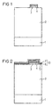
- FIGS 1 to 3 show a schematic representation of the inventive method.
- oxide is deposited several times as part of normal process control, so that finally an oxide layer up to 2 ⁇ m thick 2 is generated.
- Titanium layer 3 serves as a barrier material for the following platinum layer 4.
- the platinum layer 4 serves in the following as a bottom electrode for the capacitor of a memory cell and is therefore with a contact (not shown) Mistake.
- the platinum layer 4 can be sputtered, for example be applied.
- Below is the platinum layer 4 and the titanium layer 3 structured. This structuring the platinum layer 4 can be analogous to by means of a TiN hard mask the structuring of the top electrode described below respectively. However, with the platinum layer 4 (bottom electrode) the TiN hard mask again after structuring away.
- the resulting structure is in Fig. 1 shown.
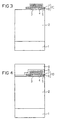
- a barium strontium titanate layer 5 (BST, (Ba, Sr) TiO 3 ) is then applied to the structure shown in FIG. 1. This layer is later used in the complete memory cell as the dielectric of the storage capacitor.
- a further platinum layer 6 is applied to the barium strontium titanate layer 5 as the first conductive layer of the electrode arrangement according to the invention.
- a titanium nitride layer 7 is subsequently produced on the platinum layer 6 as the second conductive layer of the electrode arrangement 10 according to the invention. The resulting structure is shown in Fig. 2.
- the titanium nitride layer 7 is now by means of a photo technique structured to act as a "hard mask” for structuring the platinum layer 6 and the barium strontium titanate layer 5 serve to be able to.
- RIE reactive ion etching
- Oxygen O 2 or a mixture of O 2 and other gases, for example argon is used as the etching gas.
- RIE reactive ion etching
- other dry etching processes such as ion etching, magnetic field-assisted reactive ion etching (MERIE, Magnetically Enhanced RIE), ECR etching (ECR, Electron Cyclotron Resonance) or inductively coupled plasma etching processes (ICP, TCP) can be used.
- non-volatile titanium oxide layers (Ti x O y ) are continuously simulated on the surface of the titanium nitride mask 7, as a result of which the etching rate of the titanium nitride mask 7 is reduced even further. Accordingly, the selectivity of the etching process is significantly increased.
- the associated lower mask erosion results in a higher dimensional accuracy of the structuring.
- the flank angle of the etching flank on the platinum layer 6 can be set over a wide range by a suitable choice of the O 2 concentration. In this way, the electrode arrangement according to the invention can be manufactured with high dimensional accuracy.
- the corresponding areas of the barium strontium titanate layer 5 are subjected to the reactive ion etching.
- oxygen O 2 or a mixture of O 2 and other gases, for example argon, is used as the etching gas in order to further "harden" the titanium nitride hard mask 7.
- the method 10 according to the invention has the advantage that through the titanium nitride layer 7 (second layer of the electrode arrangement), with approximately constant capacity, the Sheet resistance of the entire electrode arrangement 10 is reduced. This switches the so-called “common plate” in the so-called “pulsed-plateline” operation of the memory cell accelerates, which increases the access time of the whole Building block shortened.
- a thin SiO 2 layer 8 is applied to the entire surface of the structure shown in FIG. 3, for example by a TEOS process. Since the deposition of an oxide layer on platinum is problematic, the titanium nitride layer 7 (second layer of the electrode arrangement) enables the capacitor of the memory cell to be encapsulated with an oxide layer. Then a lacquer layer 9 is applied to the thin SiO 2 layer 8. The resulting structure is shown in Fig. 4.
- a plasma etching process is subsequently carried out in order to To produce contact holes 12 and 13. Because of the different Depth of contact holes 12 and 13 is the electrode arrangement 10 exposed to a long overetch.
- the electrode assembly 10 has through the titanium nitride layer 7 (second layer of the electrode arrangement) greater thickness, so that a break through the electrode arrangement 10 is avoided during contact hole etching.
Description
Bei der Entwicklung von hochintegrierten Speicherbausteinen, wie z.B. DRAMs bzw. FRAMs sollte die Zellkapazität bei der fortschreitenden Miniaturisierung beibehalten oder sogar noch verbessert werden. Zur Erreichung dieses Ziels werden immer dünnere dielektrische Schichten und gefaltete Kondensatorelektroden (Trench-Zelle, Stack-Zelle) verwendet. In letzter Zeit werden anstatt des herkömmlichen Siliziumoxids neue Materialien, insbesondere Paraelektrika und Ferroelektrika, zwischen den Kondensatorelektroden einer Speicherzelle verwendet. Beispielsweise kommen Bariumstrontiumtitanat (BST, (Ba,Sr)TiO3), Bleizirkontitanat (PZT, Pb(Zr,Ti)O3) bzw. Lanthan-dotiertes Bleizirkontitanat oder Strontiumwismuttantalat (SBT, SrBi2Ta2O9) für die Kondensatoren der Speicherzellen bei DRAMs bzw. FRAMs zum Einsatz.In the development of highly integrated memory devices, such as DRAMs or FRAMs, the cell capacity should be maintained or even improved as miniaturization progresses. To achieve this goal, ever thinner dielectric layers and folded capacitor electrodes (trench cell, stack cell) are used. Recently, instead of the conventional silicon oxide, new materials, in particular paraelectrics and ferroelectrics, have been used between the capacitor electrodes of a memory cell. For example, barium strontium titanate (BST, (Ba, Sr) TiO 3 ), lead zirconium titanate (PZT, Pb (Zr, Ti) O 3 ) or lanthanum-doped lead zirconium titanate or strontium bismuth tantalate (SBT, SrBi 2 Ta 2 O 9 ) come for the capacitors of Memory cells are used in DRAMs or FRAMs.
Dabei werden diese Materialien üblicherweise auf bereits vorhandenen Elektroden (Bodenelektroden) abgeschieden. Die Prozessierung erfolgt unter hohen Temperaturen, so daß die Materialien, aus denen normalerweise die Kondensatorelektroden bestehen, so z.B. dotiertes Polysilizium, leicht oxidiert werden und ihre elektrisch leitenden Eigenschaften verlieren, was zum Ausfall der Speicherzelle führen würde.These materials are usually based on existing ones Electrodes (bottom electrodes) deposited. The processing takes place at high temperatures so that the materials which usually make up the capacitor electrodes exist, e.g. doped polysilicon, slightly oxidized and lose their electrically conductive properties, which would lead to the failure of the memory cell.
Wegen ihrer guten Oxidationsbeständigkeit und/oder der Ausbildung elektrisch leitfähiger Oxide gelten 4d und 5d Übergangsmetalle, insbesondere Platinmetalle (Ru, Rh, Pd, Os, Ir, Pt) und insbesondere Platin selbst, sowie Rhenium als aussichtsreiche Kandidaten, die dotiertes Polysilizium als Elektrodenmaterial in den obengenannten Speicherzellen ersetzen könnten (US 5,585,300).Because of their good oxidation resistance and / or training electrically conductive oxides apply 4d and 5d transition metals, especially platinum metals (Ru, Rh, Pd, Os, Ir, Pt) and especially platinum itself, as well as rhenium as promising Candidates who consider doped polysilicon Replace electrode material in the memory cells mentioned above could (US 5,585,300).
Um aus den genannten, bisher in der Halbleitertechnologie noch nicht verbreiteten Materialien eine Speicherzelle aufbauen zu können, müssen dünne Schichten dieser Materialien strukturiert werden.To get out of those mentioned so far in semiconductor technology build a memory cell for materials that are not yet widespread To be able to do that, thin layers of these materials be structured.
Die Strukturierung der bisher verwendeten Materialien erfolgt in der Regel durch sogenannte plasmaunterstützte anisotrope Ätzverfahren. Dabei werden üblicherweise physikalischchemische Verfahren angewandt, bei denen Gasgemische aus einem oder mehreren reaktiven Gasen, wie z.B. Sauerstoff, Chlor, Brom, Chlorwasserstoff, Bromwasserstoff bzw. halogenierten Kohlenwasserstoffen und aus Edelgasen (z.B. Ar, He) verwendet werden. Diese Gasgemische werden in der Regel in einem elektromagnetischen Wechselfeld bei geringen Drücken angeregt (US 5,515,984).The materials used so far are structured usually through so-called plasma-assisted anisotropic Etching process. Usually physical-chemical Process used in which gas mixtures from a or several reactive gases, e.g. Oxygen, Chlorine, bromine, hydrogen chloride, hydrogen bromide or halogenated Hydrocarbons and noble gases (e.g. Ar, He) be used. These gas mixtures are usually in an alternating electromagnetic field at low pressures excited (US 5,515,984).
Fig. 7 zeigt die prinzipielle Arbeitsweise einer Ätzkammer,
dargestellt am Beispiel eines Parallelplattenreaktors 20. Das
Gasgemisch, z.B. Ar und Cl2, wird über den Gaseinlass 21 der
eigentlichen Reaktorkammer 22 zugeführt und durch den Gasauslass
29 wieder abgepumpt. Die untere Platte 24 des Parallelplattenreaktors
ist über eine Kapazität 27 mit einer Hochfrequenzquelle
28 verbunden und dient als Substrathalter. Durch
das Anlegen eines hochfrequenten elektrischen Wechselfeldes
an die obere und die untere Platte 23, 24 des Parallelplattenreaktors
wird das Gasgemisch in ein Plasma 25 überführt.
Da die Beweglichkeit der Elektronen größer als die der Gaskationen
ist, laden sich die obere und die untere Platte 23, 24
gegenüber dem Plasma 25 negativ auf. Daher üben beide Platten
23, 24 auf die positiv geladenen Gaskationen eine hohe Anziehungskraft
aus, so daß sie einem permanenten Bombardement
durch diese Ionen, z.B. Ar+ ausgesetzt sind. Da der Gasdruck
zudem niedrig gehalten wird, typischerweise 0.1 - 10 Pa, findet
nur eine geringfügige Streuung der Ionen untereinander
und an den Neutralteilchen statt, und die Ionen treffen nahezu
senkrecht auf die Oberfläche eines Substrats 26, das auf
der unteren Platte 24 des Parallelplattenreaktors gehalten
ist. Dies erlaubt eine gute Abbildung einer Maske (nicht gezeigt)
auf die darunterliegende, zu ätzende Schicht des Substrats
26.FIG. 7 shows the basic mode of operation of an etching chamber, illustrated using the example of a
Üblicherweise werden als Maskenmaterialien Photolacke verwendet, da diese durch einen Belichtungsschritt und einen Entwicklungsschritt relativ einfach strukturiert werden können.Photoresists are usually used as mask materials, since this involves an exposure step and a development step can be structured relatively easily.
Der physikalische Teil der Ätzung wird durch Impuls und kinetische Energie der auftreffenden Ionen (z.B. Cl2 +, Ar+) bewirkt. Zusätzlich werden dadurch chemische Reaktionen zwischen dem Substrat und den reaktiven Gasteilchen (Ionen, Moleküle, Atome, Radikale) unter Bildung flüchtiger Reaktionsprodukte initiiert oder verstärkt (chemischer Teil der Ätzung). Diese chemischen Reaktionen zwischen den Substratteilchen und den Gasteilchen sind verantwortlich für hohe Selektivitäten des Ätzprozesses.The physical part of the etching is caused by momentum and kinetic energy of the impinging ions (eg Cl 2 + , Ar + ). In addition, chemical reactions between the substrate and the reactive gas particles (ions, molecules, atoms, radicals) are initiated or intensified to form volatile reaction products (chemical part of the etching). These chemical reactions between the substrate particles and the gas particles are responsible for high selectivities of the etching process.
Leider hat sich herausgestellt, daß die oben genannten, in Speicherzellen neu eingesetzten Materialien zu den trockenchemisch nur schwer oder nicht ätzbaren Materialien gehören, bei denen der Ätzabtrag, auch bei der Verwendung "reaktiver" Gase, überwiegend oder fast ausschließlich auf dem physikalischen Anteil der Ätzung beruht (siehe z. B. US 5,515,984).Unfortunately, it has been found that the above, in Storage cells newly used materials to dry chemical belong only with difficult or non-etchable materials, where the etching removal, even when using "reactive" Gases, predominantly or almost exclusively on the physical Proportion of the etching is based (see, for example, US 5,515,984).
Wegen der geringen oder fehlenden chemischen Komponente der Ätzung liegt der Ätzabtrag der zu strukturierenden Schicht in der selben Größenordnung wie der Ätzabtrag der Maske bzw. der Unterlage (Ätzstoppschicht), d.h. die Ätzselektivität zur Ätzmaske bzw. Unterlage ist im allgemeinen klein (zwischen etwa 0,3 und 3,0). Dies hat zur Folge, daß durch die Erosion von Masken mit geneigten Flanken und die unvermeidliche Facettenbildung der Masken nur eine geringe Maßhaltigkeit der Strukturierung gewährleistet werden kann. Zur Verbesserung der Selektioität der Ätzung wird daher in der US 5,350,705 die Verwendung einer nach der Ätzung entfernten Titan-Hartmaske vorgeschlagen.Because of the low or no chemical component of the Etching is the etching removal of the layer to be structured the same order of magnitude as the etching removal of the mask or Underlay (etch stop layer), i.e. the etch selectivity for Etching mask or underlay is generally small (between about 0.3 and 3.0). As a result, erosion of masks with sloping flanks and the inevitable faceting the masks have a low dimensional accuracy Structuring can be guaranteed. For improvement the selectivity of the etching is therefore described in US Pat. No. 5,350,705 the use of a titanium hard mask removed after the etching proposed.
Die genannten Probleme treten auch bei der Strukturierung der Topelelektrode einer Speicherzelle auf, die nach dem Prinzip "capacitor over bitline" mit einem sogenannten "stacked capacitor" aufgebaut ist.The problems mentioned also occur when structuring the Topel electrode of a memory cell based on the principle "capacitor over bitline" with a so-called "stacked capacitor" is constructed.
Darüber hinaus führt die Verwendung eines "stacked capacitors" zu Schwierigkeiten bei der Kontaktierung der Speicherzelle. Zum Anschluß der Speicherzelle an eine Metallisierung sind Kontaktlöcher unterschiedlicher Tiefe in eine über und um den Kondensator angeordnete Isolationschicht zu ätzen. Dabei soll diese Kontakloch-Ätzung in unterschiedlichen Tiefen selektiv zu verschiedenen Materialien stoppen. Zur Vereinfachung des Herstellungsprozesses ist die Verwendung von nur einer Maskenebene anzustreben.In addition, the use of a "stacked capacitors" difficulties in contacting the memory cell. For connecting the memory cell to a metallization are contact holes of different depths in an over and to etch the insulation layer arranged on the capacitor. there this contact hole etching should be at different depths selectively stop to different materials. For simplification The manufacturing process is using only to strive for a mask level.
Bei einer Speicherzelle nach dem Prinzip "capacitor over bitline" mit einem "stacked capacitor" muß die Kontakloch-Ätzung zuerst auf dem Material der Topelektrode des Kondensators stoppen (US 5,350,705 und US 5,585,300). Dementsprechend ist das Material der Topelektrode das Material, das der größten Überätzung ausgesetzt ist, während andere Kontaktlöcher zu tiefer liegenden Schichten weitergeätzt werden. Besteht die Topelektrode beispielsweise aus Platin, so kann es neben einem Durchbruch der Topelektrode auch zu einer Redeposition von abgesputterten Platin an den Innenwänden der Maskenöffnung kommen. Dies führt zu sogenannten "Fences", dünnen und leitfähigen Strukturen, die auch nach einem Veraschen der Lackmaske bestehen bleiben und zu Kurzschlüssen führen können (US 5,515,984). Außerdem ist es aufgrund der hohen chemischen Inertheit der neu eingesetzten Materialien schwierig, derartige "Fences" aus den Kontaktlöchern zu entfernen. With a memory cell based on the principle of "capacitor over bitline" the contact hole etching must be carried out with a "stacked capacitor" first on the material of the top electrode of the capacitor stop (US 5,350,705 and US 5,585,300). Is accordingly the material of the top electrode the material of the largest Overetched while exposed to other vias deeper layers are further etched. Does it exist Top electrode made of platinum, for example, so it can be next to one Breakthrough of the top electrode also to a speech position of sputtered platinum on the inner walls of the mask opening come. This leads to so-called "fences", thin and conductive structures, even after the ashing of the Paint mask remain and can lead to short circuits (US 5,515,984). It is also due to the high chemical Inertness of the newly used materials difficult, such Remove "fences" from the contact holes.
Außerdem wird auf den Artikel "WSi2/Polysilicon Gate Etching
Using TiN Hard Mask in Conjunction with Photoresist", S. Tabara,
Jpn. J. Appl. Phys. Vol 36 (1997) pp. 2508-2513, Part
1, No. 4B, April 1997, die Patentschrift US 5,122,225 sowie
die nicht vorveröffentlichte Patentschrift US 5,773,314 hingewiesen.The article "WSi2 / Polysilicon Gate Etching
Using TiN Hard Mask in Conjunction with Photoresist ", S. Tabara,
Jpn. J. Appl. Phys. Vol 36 (1997) pp. 2508-2513,
Es ist daher die Aufgabe der vorliegenden Erfindung, ein Verfahren zur Erzeugung einer Elektrodenanordnung bereitzustellen, das die genannten Nachteile vermeidet oder mindert.It is therefore the object of the present invention a method for producing an electrode arrangement to provide, which avoids the disadvantages mentioned or decreases.
Diese Aufgabe wird durch ein Verfahren gemäß Patentanspruch 1
gelöst. Weitere vorteilhafte Ausführungsformen, Ausgestaltungen
und Aspekte der vorliegenden Erfindung ergeben sich aus
den Unteransprüchen der Beschreibung und den beiliegenden
Zeichnungen. This object is achieved by a method according to
Dabei soll unter einer chemischen Trockenätzung eine übliche chemische Trockenätzung unter Verwendung von, möglicherweise angeregten, Halogenen, Halogenwasserstoffen oder halogenierten Kohlenwasserstoffen oder unter Verwendung von Sauerstoff bei üblichen Temperaturen und Gasdrücken verstanden werden. Weiterhin soll unter einem Material, das durch eine chemische Trockenätzung praktisch nicht ätzbar ist, ein Material verstanden werden, das bei für das jeweilige Material optimalen Prozeßbedingungen eine Ätzrate von kleiner als 1 nm/min aufweist. Dementsprechend soll unter einer geringen Ätzrate eine Ätzrate größer als 1 nm/min bei für das jeweilige Material optimalen Prozeßbedingungen verstanden werden.A chemical dry etching is said to be a common practice dry chemical etching using, possibly excited, halogens, hydrogen halides or halogenated Hydrocarbons or using oxygen can be understood at usual temperatures and gas pressures. It is also said to be under a material that is chemical Dry etching is practically not etchable, a material is understood be the optimum for the respective material Process conditions has an etching rate of less than 1 nm / min. Accordingly, under a low etching rate Etching rate greater than 1 nm / min for the respective material optimal process conditions can be understood.
Da das Material der ersten Schicht durch eine chemische Trockenätzung praktisch nicht ätzbar ist, wird die erste Schicht während einer üblichen chemisch-physikalischen Trockenätzung vorwiegend durch den physikalischen Teil der chemisch-physikalischen Trockenätzung abgetragen. Im Gegensatz dazu wird die zweite Schicht während einer üblichen chemisch-physikalischen Trockenätzung auch durch den chemischen Teil der chemisch-physikalischen Trockenätzung abgetragen.Because the material of the first layer is dry chemical etched is practically not etchable, the first layer during a normal chemical-physical dry etching mainly through the physical part of the chemical-physical Dry etching removed. In contrast to becomes the second layer during a usual chemical-physical Dry etching also through the chemical part the chemical-physical dry etching.
Die Erfindung hat den Vorteil, daß sich die effektive Dicke der Elektrodenanordnung um die Höhe der zweiten Schicht erhöht, so daß ein Durchbrechen während der Überätzung bei einer Kontaktierung der Elektrodenanordnung vermieden wird. Ebenso wird die Bildung von nur schwer entfernbaren Redepositionen aus dem Material der ersten Schicht während der Überätzung verhindert.The invention has the advantage that the effective thickness the electrode arrangement is increased by the height of the second layer, so that a breakdown during overetching at a Contacting the electrode arrangement is avoided. As well is the formation of difficult-to-remove speech positions from the material of the first layer during the overetch prevented.
Weiterhin reduziert sich durch die zweite Schicht der Elektrodenanordnung - bei etwa gleichbleibender Kapazität - der Schichtwiderstand der Elektrodenanordnung. Dadurch wird das Schalten der sogenannten "common plate" beim sogenannten "pulsed-plateline" Betrieb der Speicherzelle beschleunigt, wodurch sich die Zugriffszeit des gesamten Bausteins verkürzt.Furthermore, the second layer reduces the electrode arrangement - with approximately constant capacity - the Sheet resistance of the electrode arrangement. This will make it Switching the so-called "common plate" in the so-called "pulsed-plateline" operation of the memory cell accelerates, which shortens the access time of the entire block.
Darüber hinaus ermöglicht die zweite Schicht der Elektrodenanordnung eine Einkapselung des Kondensators der Speicherzelle mit einer Oxidschicht.In addition, the second layer enables the electrode arrangement an encapsulation of the capacitor of the memory cell with an oxide layer.
Bevorzugt enthält die erste Schicht ein 4d oder 5d Übergangsmetall, deren leitende Nitride oder deren leitende OxideThe first layer preferably contains a 4d or 5d transition metal, their conductive nitrides or their conductive oxides
Insbesondere enthält die erste Schicht Ruthenium, Rhodium, Palladium, Osmium, Iridium, Platin, Gold, Silber oder Rhenium.In particular, the first layer contains ruthenium, rhodium, Palladium, osmium, iridium, platinum, gold, silver or rhenium.
Weiterhin ist es bevorzugt, wenn die zweite Schicht Aluminium, Titan, Wolfram, deren leitende Silizide, deren leitende Nitride oder deren leitende Oxide enthält.It is further preferred if the second layer is aluminum, Titanium, tungsten, their conductive silicides, their conductive Contains nitrides or their conductive oxides.
Insbesondere enthält die zweite Schicht Titan oder ein Titannitrid, insbesondere TiNx 0.8 < x < 1.2.In particular, the second layer contains titanium or a titanium nitride, in particular TiN x 0.8 <x <1.2.
Die Erfindung hat den weiteren Vorteil, daß die Metalle, Metallsilizide, Metallnitride oder Metalloxide der zweiten Schicht im Vergleich zu Photolacken widerstandsfähiger sind, so daß ein chemisches "Veraschen" der Maske verhindert wird. Die hohe Bindungsenergie der Metallatome in Metallen bzw. der Metallionen in Siliziden, Nitriden oder Oxiden führt zu sehr geringen Abtragsraten bei Ätzprozessen mit einem hohen physikalischen Anteil. Dies hat insgesamt zur Folge, daß die Selektivität des Ätzprozesses der ersten Schicht erhöht wird. Durch die geringere Maskenerosion ergibt sich eine höhere Maßhaltigkeit der Strukturierung. Darüber hinaus lassen sich durch das erfindungsgemäße Verfahren auch mit reaktiven Gasen steilere Ätzflanken an der zu strukturierenden Schicht erzielen.The invention has the further advantage that the metals, metal silicides, Metal nitrides or metal oxides of the second Layer are more resistant compared to photoresists, so that chemical "ashing" of the mask is prevented. The high binding energy of the metal atoms in metals or Metal ions in silicides, nitrides or oxides leads to a lot low removal rates in etching processes with a high physical Proportion of. Overall, this has the consequence that the selectivity the etching process of the first layer is increased. The lower mask erosion results in a higher one Dimensional accuracy of the structuring. Beyond that by the method according to the invention also with reactive gases achieve steeper etching edges on the layer to be structured.
Bevorzugt wird zum Trockenätzen der zweiten Schicht ein Plasmaätzverfahren verwendet.A plasma etching method is preferred for dry etching of the second layer used.
Weiterhin ist es bevorzugt, wenn während der Trockenätzung der ersten Schicht zumindest ein reaktiver Stoff, insbesondere ein reaktives Gas, vorgesehen ist, der mit dem Material der zweiten Schicht an der Oberfläche der zweiten Schicht zu einer nicht flüchtigen Verbindung reagiert. Auf diese Weise wird der chemische Teil einer chemisch-physikalischen Trockenätzung reduziert und der Abtrag der Ätzung wird im wesentlichen durch den physikalischen Teil der Ätzung bestimmt. Furthermore, it is preferred if during the dry etching the first layer at least one reactive substance, in particular a reactive gas is provided which is compatible with the material the second layer on the surface of the second layer of a non-volatile connection. In this way becomes the chemical part of a chemical-physical dry etching is reduced and the removal of the etching becomes essentially determined by the physical part of the etching.
Dabei ist es bevorzugt, daß das reaktive Gas aus einer Gruppe ausgewählt ist, die aus den Gasen Sauerstoff (O2), Stickstoff (N2), Wasserstoff (H2), Halogenen, gasförmige Halogenverbindungen oder einer Mischung dieser Gase besteht.It is preferred that the reactive gas is selected from a group consisting of the gases oxygen (O 2 ), nitrogen (N 2 ), hydrogen (H 2 ), halogens, gaseous halogen compounds or a mixture of these gases.
Weiterhin ist es bevorzugt, wenn während der Trockenätzung der ersten Schicht ein Edelgas, bevorzugt Argon, vorgesehen ist.Furthermore, it is preferred if during the dry etching an inert gas, preferably argon, is provided in the first layer is.
Vorteilhafterweise werden zur Trockenätzung der ersten Schicht eine reaktive Ionenätzung (RIE, Reactive Ion Etching), eine magnetfeldunterstützte reaktive Ionenätzung (MERIE, Magnetically Enhanced RIE), eine ECR-Ätzung (ECR, Electron Cyclotron Resonance) oder induktiv gekoppelte Plasmaätzverfahren (ICP, TCP) eingesetzt.The first is advantageously used for dry etching Layer a reactive ion etching (RIE, Reactive Ion Etching), a magnetic field assisted reactive ion etching (MERIE, Magnetically Enhanced RIE), an ECR etching (ECR, Electron Cyclotron Resonance) or inductively coupled plasma etching (ICP, TCP) used.
Es ist bevorzugt, wenn die Isolationsschicht eine Siliziumoxidschicht ist oder enthält.It is preferred if the insulation layer is a silicon oxide layer is or contains.
Weiterhin ist es bevorzugt, wenn die Siliziumoxidschicht durch einen TEOS- oder einen Silan-Prozess erzeugt wird.It is further preferred if the silicon oxide layer is generated by a TEOS or a silane process.
Als leitende Schicht wird vorteilhafterweise eine Aluminium-, Wolfram- oder Kupferschicht verwendet.Advantageously, an aluminum, Tungsten or copper layer used.
Die Erfindung wird nachfolgend anhand von Figuren der Zeichnung
näher dargestellt. Es zeigen:
Die Figuren 1 bis 3 zeigen eine schematische Darstellung des
erfindungsgemäßen Verfahrens. Auf einem Siliziumsubstrat 1
wird im Rahmen der normalen Prozeßführung mehrfach Oxid abgeschieden,
so daß schließlich eine bis zu 2 µm dicke Oxidschicht
2 erzeugt wird. Eine auf die Oxidschicht 2 aufgebrachte
Titanschicht 3 dient als Barrierenmaterial für die
folgende Platinschicht 4. Die Platinschicht 4 dient im folgenden
als Bottomelektrode für den Kondensator einer Speicherzelle
und ist deshalb mit einem Kontakt (nicht gezeigt)
versehen. Die Platinschicht 4 kann beispielsweise durch Sputtern
aufgebracht werden. Nachfolgend werden die Platinschicht
4 und die Titanschicht 3 strukturiert. Diese Strukturierung
der Platinschicht 4 kann mittels einer TiN-Hardmask analog zu
der im folgenden beschriebenen Strukturierung der Topelektrode
erfolgen. Jedoch wird bei der Platinschicht 4 (Bottomelektrode)
die TiN-Hardmask nach der Strukturierung wieder
entfernt. Die sich daraus ergebende Struktur ist in Fig. 1
gezeigt.Figures 1 to 3 show a schematic representation of the
inventive method. On a
Anschließend wird eine Bariumstrontiumtitanatschicht 5 (BST,
(Ba,Sr)TiO3) auf die in Fig. 1 gezeigte Struktur aufgebracht.
Diese Schicht wird später in der vollständigen Speicherzelle
als Dielektrikum des Speicherkondensators verwendet. Auf die
Bariumstrontiumtitanatschicht 5 wird eine weitere Platinschicht
6 als erste leitende Schicht der erfindungsgemäßen
Elektrodenanordnung aufgebracht. Nachfolgend wird eine Titannitrid-Schicht
7 als zweite leitende Schicht der erfindungsgemäßen
Elektrodenanordnung 10 auf der Platinschicht 6 erzeugt.
Die sich daraus ergebende Struktur ist in Fig. 2 gezeigt.A barium strontium titanate layer 5 (BST, (Ba, Sr) TiO 3 ) is then applied to the structure shown in FIG. 1. This layer is later used in the complete memory cell as the dielectric of the storage capacitor. A further platinum layer 6 is applied to the barium
Die Titannitridschicht 7 wird nun mittels einer Phototechnik
strukturiert, um als "Hardmask" zur Strukturierung der Platinschicht
6 und der Bariumstrontiumtitanatschicht 5 dienen
zu können.The titanium nitride layer 7 is now by means of a photo technique
structured to act as a "hard mask" for structuring the platinum layer
6 and the barium
Nachfolgend wird ein reaktives Ionenätzen (RIE, Reactive Ion Etching) durchgeführt, um die Platinschicht 6 einem chemisch-physikalischen Trockenätzen zu unterziehen. Als Ätzgas wird dabei Sauerstoff O2 oder ein Gemisch aus O2 und weiteren Gasen, z.B. Argon, verwendet. Anstatt des reaktiven Ionenätzens können auch andere Trockenätzverfahren wie beispielsweise das Ionenätzen, das magnetfeldunterstützte reaktive Ionenätzen (MERIE, Magnetically Enhanced RIE), das ECR-Ätzen (ECR, Electron Cyclotron Resonance) oder induktiv gekoppelte Plasmaätzverfahren (ICP, TCP) eingesetzt werden.Subsequently, a reactive ion etching (RIE, Reactive Ion Etching) is carried out in order to subject the platinum layer 6 to a chemical-physical dry etching. Oxygen O 2 or a mixture of O 2 and other gases, for example argon, is used as the etching gas. Instead of reactive ion etching, other dry etching processes such as ion etching, magnetic field-assisted reactive ion etching (MERIE, Magnetically Enhanced RIE), ECR etching (ECR, Electron Cyclotron Resonance) or inductively coupled plasma etching processes (ICP, TCP) can be used.
Während des Trockenätzens der Platinschicht 6 werden auf der Oberfläche der Titannitridmaske 7 laufend nicht flüchtige Titanoxidschichten (TixOy) nachgebildet, wodurch die Ätzrate der Titannitridmaske 7 noch weiter gesenkt wird. Entsprechend wird somit die Selektivität des Ätzprozesses deutlich erhöht. Durch die damit verbundene geringere Maskenerosion ergibt sich eine höhere Maßhaltigkeit der Strukturierung. Durch eine geeignete Wahl der O2-Konzentration läßt sich der Flankenwinkel der Ätzflanke an der Platinschicht 6 über einen großen Bereich einstellen. Auf diese Weise läßt sich die erfindungsgemäße Elektrodenanordnung mit hoher Maßhaltigkeit herstellen.During the dry etching of the platinum layer 6, non-volatile titanium oxide layers (Ti x O y ) are continuously simulated on the surface of the titanium nitride mask 7, as a result of which the etching rate of the titanium nitride mask 7 is reduced even further. Accordingly, the selectivity of the etching process is significantly increased. The associated lower mask erosion results in a higher dimensional accuracy of the structuring. The flank angle of the etching flank on the platinum layer 6 can be set over a wide range by a suitable choice of the O 2 concentration. In this way, the electrode arrangement according to the invention can be manufactured with high dimensional accuracy.
Sind die durch die Titannitridmaske nicht geschützten Bereiche
der Platinschicht 6 entfernt, werden die entsprechenden
Bereiche der Bariumstrontiumtitanatschicht 5 dem reaktiven
Ionenätzen unterzogen. Wiederum wird als Ätzgas dabei Sauerstoff
O2 oder ein Gemisch aus O2 und weiteren Gasen, z.B. Argon,
verwendet, um die Titannitrid-Hardmask 7 weiter zu "härten".If the areas of the platinum layer 6 which are not protected by the titanium nitride mask are removed, the corresponding areas of the barium
Anstatt des reaktiven Ionenätzens können auch bei der Trockenätzung
der Bariumstrontiumtitanatschicht 5 andere Trockenätzverfahren
wie beispielsweise das Ionenätzen, das magnetfeldunterstützte
reaktive Ionenätzen (MERIE, Magnetically
Enhanced RIE), das ECR-Ätzen (ECR, Electron Cyclotron Resonance)
oder induktiv gekoppelte Plasmaätzverfahren (ICP, TCP)
eingesetzt werden. Die sich nach der Trockenätzung der Bariumstrontiumtitanatschicht
5 ergebende Struktur ist in Fig. 3
gezeigt.Instead of reactive ion etching, you can also use dry etching
the barium
Das erfindungsgemäße Verfahren 10 hat den Vorteil, daß sich
durch die Titannitridschicht 7 (zweite Schicht der Elektrodenanordnung),
bei etwa gleichbleibender Kapazität, der
Schichtwiderstand der gesamten Elektrodenanordnung 10 verringert.
Dadurch wird das Schalten der sogenannten "common plate"
beim sogenannten "pulsed-plateline" Betrieb der Speicherzelle
beschleunigt, wodurch sich die Zugriffszeit des gesamten
Bausteins verkürzt.The
Auf die in Fig. 3 gezeigte Struktur wird zur Isolation ganzflächig
eine dünne SiO2-Schicht 8, beispielsweise durch einen
TEOS-Prozeß, aufgebracht. Da die Abscheidung einer Oxidschicht
auf Platin problematisch ist, ermöglicht die Titannitridschicht
7 (zweite Schicht der Elektrodenanordnung) eine
Einkapselung des Kondensators der Speicherzelle mit einer Oxidschicht.
Anschließend wird auf die dünne SiO2-Schicht 8
eine Lackschicht 9 aufgebracht. Die sich daraus ergebende
Struktur ist in Fig. 4 gezeigt. A thin SiO 2 layer 8 is applied to the entire surface of the structure shown in FIG. 3, for example by a TEOS process. Since the deposition of an oxide layer on platinum is problematic, the titanium nitride layer 7 (second layer of the electrode arrangement) enables the capacitor of the memory cell to be encapsulated with an oxide layer. Then a
An den Stellen, an denen später Kontaktlöcher entstehen sollen
wird die Lackschicht 9 belichtet. Anschließend wird die
Lackmaske entwickelt, d.h. die belichteten Bereiche der Lackschicht
9 werden entfernt. Die sich daraus ergebende Struktur
ist in Fig. 5 gezeigt.At the points where contact holes are to be created later
the
Nachfolgend wird ein Plasmaätzprozeß durchgeführt, um die
Kontaktlöcher 12 und 13 zu erzeugen. Durch die unterschiedliche
Tiefe der Kontaktlöcher 12 und 13 ist die Elektrodenanordnung
10 einer langen Überätzung ausgesetzt.A plasma etching process is subsequently carried out in order to
To produce
Jedoch besitzt die Elektrodenanordnung 10 durch die Titannitridschicht
7 (zweite Schicht der Elektrodenanordnung) eine
größere Dicke, so daß ein Durchbrechen der Elektrodenanordnung
10 während der Kontaktlochätzung vermieden wird.However, the
Ebenso wird die Bildung von nur schwer entfernbaren Redepositionen aus dem Material der ersten Schicht (Platinschicht 6) während der Überätzung verhindert.Likewise, the formation of difficult-to-remove speech positions from the material of the first layer (platinum layer 6) prevented during the overetch.
Anschließend wird noch die Lackschicht 9 entfernt, wodurch
sich die in Fig. 6 gezeigte Struktur ergibt.Then the
Claims (11)
- Method for producing an electrode arrangement (10) having the steps:a first conductive layer (6) of the electrode arrangement (10) is made available, the material of the first layer (6) being virtually impossible to etch by means of chemical dry etching,a second conductive layer (7) of the electrode arrangement (10) is made available on the first layer (6), the material of the second layer (7) being etchable by means of chemical dry etching with a low etching rate,the second layer (7) is structured by means of chemical-physical dry etching, the second layer (7) being also deposited by the chemical part of the chemical-physical dry etching during the chemical-physical dry etching,the first layer (6) of the electrode arrangement (10) is dry etched by a chemical-physical process using the second structured layer (7) as a mask, the first layer (6) being predominantly deposited by the physical part of the chemical-physical dry etching during the chemical-dry etching,at least one insulating layer (8) is applied to the electrode arrangement (10) and patterned in such a way that at least one contact hole (12) to the electrode arrangement (10) and one further contact hole (13), arranged outside the electrode arrangement, are formed, with the result that due to a different depth of the contact holes (12, 13) the electrode arrangement (10) is subjected to long over-etching, in which the electrode arrangement (10) is prevented from breaking through during the etching of the contact holes owing to the greater thickness which the electrode arrangement (10) has as a result of the second layer (7), anda conductive layer is deposited so that the contact holes (12, 13) are filled in.
- Method according to Claim 1, characterized in that the first layer (6) contains a 4d or 5d transition metal, its conductive nitrides or its conductive oxides.
- Method according to Claim 1 or 2, characterized in that the second layer (7) contains aluminium, titanium, tungsten, their conductive silicides, their conductive nitrides or their conductive oxides.
- Method according to one of Claims 1 to 3, characterized in that the first layer (6) contains ruthenium, rhodium, palladium, osmium, iridium, platinum, gold, silver or rhenium.
- Method according to one of Claims 1 to 4, characterized in that the second layer (7) contains titanium or a titanium nitride, in particular TiNx 0.8 < x < 1.2.
- Method according to one of the preceding claims, characterized in that a plasma etching method is used for dry-etching the second layer (7).
- Method according to one of the preceeding claims, characterized in that, during the dry-etching of the first layer (6), at least one reactive substance is provided which reacts with the material of the second layer (7) on the surface of the second layer (7) to form a non-volatile compound, and in that the reactive gas is oxygen (O2), nitrogen (N2), hydrogen (H2), a halogen, a gaseous halogen compound or a mixture of these gases or an inert gas.
- Method according to one of the preceding claims, characterized in that reactive ion etching (RIE), magnetically enhanced reactive ion etching (MERIE), ECR (Electron Cyclotron Resonance) etching or inductively coupled plasma etching methods (ICP, TCP) are used for dry-etching the first layer (6).
- Method according to one of the preceding claims, characterized in that the insulation layer (8) is a silicon oxide layer, or contains a silicon layer.
- Method according to Claim 9, characterized in that the silicon oxide layer (8) is produced by means of a TEOS process or a silane process.
- Method according to one of the preceding claims, characterized in that an aluminium, tungsten or copper layer is used as conductive layer.
Applications Claiming Priority (2)
| Application Number | Priority Date | Filing Date | Title |
|---|---|---|---|
| DE19728474 | 1997-07-03 | ||
| DE19728474A DE19728474A1 (en) | 1997-07-03 | 1997-07-03 | Electrode arrangement |
Publications (3)
| Publication Number | Publication Date |
|---|---|
| EP0889508A2 EP0889508A2 (en) | 1999-01-07 |
| EP0889508A3 EP0889508A3 (en) | 1999-06-02 |
| EP0889508B1 true EP0889508B1 (en) | 2002-05-08 |
Family
ID=7834561
Family Applications (1)
| Application Number | Title | Priority Date | Filing Date |
|---|---|---|---|
| EP98111994A Expired - Lifetime EP0889508B1 (en) | 1997-07-03 | 1998-06-29 | Process for the dry etching of an electrode structure |
Country Status (7)
| Country | Link |
|---|---|
| US (1) | US7045070B1 (en) |
| EP (1) | EP0889508B1 (en) |
| JP (1) | JPH11233725A (en) |
| KR (1) | KR100446580B1 (en) |
| CN (1) | CN1146960C (en) |
| DE (2) | DE19728474A1 (en) |
| TW (1) | TW414954B (en) |
Families Citing this family (8)
| Publication number | Priority date | Publication date | Assignee | Title |
|---|---|---|---|---|
| DE19901002B4 (en) * | 1999-01-13 | 2005-09-22 | Infineon Technologies Ag | Method for structuring a layer |
| DE19935131B4 (en) * | 1999-07-27 | 2006-01-26 | Infineon Technologies Ag | Method for eliminating redepositions from a wafer |
| DE10004391C2 (en) * | 2000-02-02 | 2002-05-16 | Infineon Technologies Ag | Process for performing a plasma etching process |
| TWI326908B (en) | 2006-09-11 | 2010-07-01 | Ind Tech Res Inst | Packaging structure and fabricating method thereof |
| US8987133B2 (en) | 2013-01-15 | 2015-03-24 | International Business Machines Corporation | Titanium oxynitride hard mask for lithographic patterning |
| US8986921B2 (en) | 2013-01-15 | 2015-03-24 | International Business Machines Corporation | Lithographic material stack including a metal-compound hard mask |
| US8853095B1 (en) | 2013-05-30 | 2014-10-07 | International Business Machines Corporation | Hybrid hard mask for damascene and dual damascene |
| JP2015133424A (en) * | 2014-01-14 | 2015-07-23 | 住友電工デバイス・イノベーション株式会社 | Electronic component manufacturing method |
Family Cites Families (22)
| Publication number | Priority date | Publication date | Assignee | Title |
|---|---|---|---|---|
| JPS6320079A (en) * | 1986-07-11 | 1988-01-27 | ヤンマー農機株式会社 | Sensor device for granular body such as cereal grain |
| US5057455A (en) * | 1989-11-30 | 1991-10-15 | At&T Bell Laboratories | Formation of integrated circuit electrodes |
| US5122225A (en) * | 1990-11-21 | 1992-06-16 | Texas Instruments Incorporated | Selective etch method |
| US5208170A (en) * | 1991-09-18 | 1993-05-04 | International Business Machines Corporation | Method for fabricating bipolar and CMOS devices in integrated circuits using contact metallization for local interconnect and via landing |
| US5269880A (en) * | 1992-04-03 | 1993-12-14 | Northern Telecom Limited | Tapering sidewalls of via holes |
| JP3086747B2 (en) * | 1992-05-07 | 2000-09-11 | 三菱電機株式会社 | Semiconductor device and manufacturing method thereof |
| US5350705A (en) * | 1992-08-25 | 1994-09-27 | National Semiconductor Corporation | Ferroelectric memory cell arrangement having a split capacitor plate structure |
| KR960005246B1 (en) * | 1992-10-21 | 1996-04-23 | 현대전자산업주식회사 | Storage electrode manufacture of capacitor |
| US5341016A (en) * | 1993-06-16 | 1994-08-23 | Micron Semiconductor, Inc. | Low resistance device element and interconnection structure |
| US5562801A (en) * | 1994-04-28 | 1996-10-08 | Cypress Semiconductor Corporation | Method of etching an oxide layer |
| KR0132831B1 (en) * | 1994-07-08 | 1998-04-16 | 김광호 | Manufacturing method of semiconductor device cell with buried bit line and pin structured capacitor |
| JP3122579B2 (en) * | 1994-07-27 | 2001-01-09 | シャープ株式会社 | Pt film etching method |
| US5585300A (en) * | 1994-08-01 | 1996-12-17 | Texas Instruments Incorporated | Method of making conductive amorphous-nitride barrier layer for high-dielectric-constant material electrodes |
| US5566045A (en) * | 1994-08-01 | 1996-10-15 | Texas Instruments, Inc. | High-dielectric-constant material electrodes comprising thin platinum layers |
| US5436190A (en) * | 1994-11-23 | 1995-07-25 | United Microelectronics Corporation | Method for fabricating semiconductor device isolation using double oxide spacers |
| KR0168346B1 (en) * | 1994-12-29 | 1998-12-15 | 김광호 | Capacitor using high deelectric material and its fabrication method |
| US5621906A (en) * | 1995-02-13 | 1997-04-15 | The Trustees Of Columbia University In The City Of New York | Perspective-based interface using an extended masthead |
| EP0739030A3 (en) | 1995-04-19 | 1998-07-08 | Nec Corporation | Highly-integrated thin film capacitor with high dielectric constant layer |
| JPH08316430A (en) | 1995-05-15 | 1996-11-29 | Mitsubishi Electric Corp | Semiconductor storage device, its manufacture, and stacked capacitor |
| US5930639A (en) * | 1996-04-08 | 1999-07-27 | Micron Technology, Inc. | Method for precision etching of platinum electrodes |
| KR100378345B1 (en) * | 1996-04-17 | 2003-06-12 | 삼성전자주식회사 | Dry etching method of platinum thin film |
| TW365691B (en) * | 1997-02-05 | 1999-08-01 | Samsung Electronics Co Ltd | Method for etching Pt film of semiconductor device |
-
1997
- 1997-07-03 DE DE19728474A patent/DE19728474A1/en not_active Ceased
-
1998
- 1998-06-10 TW TW087109246A patent/TW414954B/en not_active IP Right Cessation
- 1998-06-29 DE DE59804023T patent/DE59804023D1/en not_active Expired - Fee Related
- 1998-06-29 EP EP98111994A patent/EP0889508B1/en not_active Expired - Lifetime
- 1998-07-01 KR KR10-1998-0026348A patent/KR100446580B1/en not_active IP Right Cessation
- 1998-07-03 CN CNB981156622A patent/CN1146960C/en not_active Expired - Fee Related
- 1998-07-03 JP JP10204409A patent/JPH11233725A/en active Pending
-
2000
- 2000-08-24 US US09/645,807 patent/US7045070B1/en not_active Expired - Fee Related
Also Published As
| Publication number | Publication date |
|---|---|
| US7045070B1 (en) | 2006-05-16 |
| JPH11233725A (en) | 1999-08-27 |
| DE59804023D1 (en) | 2002-06-13 |
| TW414954B (en) | 2000-12-11 |
| EP0889508A2 (en) | 1999-01-07 |
| KR100446580B1 (en) | 2004-11-16 |
| KR19990013499A (en) | 1999-02-25 |
| CN1204861A (en) | 1999-01-13 |
| CN1146960C (en) | 2004-04-21 |
| EP0889508A3 (en) | 1999-06-02 |
| DE19728474A1 (en) | 1999-01-07 |
Similar Documents
| Publication | Publication Date | Title |
|---|---|---|
| DE19625883C2 (en) | Capacitor structure of a semiconductor device and method for producing the same | |
| EP0895278A2 (en) | Patterning process | |
| DE10014315B4 (en) | Method for producing a semiconductor memory | |
| DE69626562T2 (en) | Process for the isotropic etching of silicon, which is highly selective towards tungsten | |
| DE69837301T2 (en) | Method of etching a platinum film in a semiconductor device | |
| DE19733391C2 (en) | Structuring process | |
| DE102004043855A1 (en) | Method for producing a magnetic tunnel junction device | |
| DE19728473A1 (en) | Layer structuring by dry etching process | |
| WO1996027208A1 (en) | Method for forming a structure using redeposition | |
| EP0889508B1 (en) | Process for the dry etching of an electrode structure | |
| EP0907203A2 (en) | Patterning method | |
| EP0889506A2 (en) | Etching process | |
| EP0902461A2 (en) | Process for forming structures with high aspect ratio | |
| WO2002015250A1 (en) | Structuring of ferroelectric layers | |
| EP1277230B1 (en) | Method for producing capacitor structures | |
| DE112004000192T5 (en) | Hard mask with high selectivity for IR barrier layers for the production of a ferroelectric capacitor | |
| DE19929307C1 (en) | Structured layer, especially a FRAM capacitor lower electrode, is produced by heat treatment to cause layer material migration from a migration region to a target region of a substrate | |
| DE3219284A1 (en) | METHOD FOR PRODUCING A SEMICONDUCTOR DEVICE | |
| DE10338422B4 (en) | Selective plasma etching process for alumina structuring and its use | |
| DE10057444A1 (en) | Production of a capacitor arrangement used for an FeRAM storage device comprises filling exposed intermediate regions of the substrate with an electrically insulating intermediate layer up to the level of an capacitor device | |
| DE112004001585T5 (en) | Fence-free etching of an iridium barrier with a steep slope angle | |
| DE10121657A1 (en) | Microelectronic structure with a hydrogen barrier layer | |
| DE19620833A1 (en) | Production of capacitor for semiconductor device | |
| DE19906814A1 (en) | Surface material removal, especially for hard mask removal from a semiconductor surface, comprises removing material while protecting the rest of the surface with a temporary layer | |
| EP0984490A1 (en) | Process for the manufacture of structured material layers |
Legal Events
| Date | Code | Title | Description |
|---|---|---|---|
| PUAI | Public reference made under article 153(3) epc to a published international application that has entered the european phase |
Free format text: ORIGINAL CODE: 0009012 |
|
| AK | Designated contracting states |
Kind code of ref document: A2 Designated state(s): DE FR GB IE IT |
|
| AX | Request for extension of the european patent |
Free format text: AL;LT;LV;MK;RO;SI |
|
| PUAL | Search report despatched |
Free format text: ORIGINAL CODE: 0009013 |
|
| AK | Designated contracting states |
Kind code of ref document: A3 Designated state(s): AT BE CH CY DE DK ES FI FR GB GR IE IT LI LU MC NL PT SE |
|
| AX | Request for extension of the european patent |
Free format text: AL;LT;LV;MK;RO;SI |
|
| 17P | Request for examination filed |
Effective date: 19990805 |
|
| AKX | Designation fees paid |
Free format text: DE FR GB IE IT |
|
| 17Q | First examination report despatched |
Effective date: 20000114 |
|
| RAP1 | Party data changed (applicant data changed or rights of an application transferred) |
Owner name: INFINEON TECHNOLOGIES AG |
|
| RTI1 | Title (correction) |
Free format text: PROCESS FOR THE DRY ETCHING OF AN ELECTRODE STRUCTURE |
|
| GRAG | Despatch of communication of intention to grant |
Free format text: ORIGINAL CODE: EPIDOS AGRA |
|
| RTI1 | Title (correction) |
Free format text: PROCESS FOR THE DRY ETCHING OF AN ELECTRODE STRUCTURE |
|
| GRAG | Despatch of communication of intention to grant |
Free format text: ORIGINAL CODE: EPIDOS AGRA |
|
| GRAG | Despatch of communication of intention to grant |
Free format text: ORIGINAL CODE: EPIDOS AGRA |
|
| GRAH | Despatch of communication of intention to grant a patent |
Free format text: ORIGINAL CODE: EPIDOS IGRA |
|
| REG | Reference to a national code |
Ref country code: GB Ref legal event code: IF02 |
|
| GRAH | Despatch of communication of intention to grant a patent |
Free format text: ORIGINAL CODE: EPIDOS IGRA |
|
| GRAA | (expected) grant |
Free format text: ORIGINAL CODE: 0009210 |
|
| AK | Designated contracting states |
Kind code of ref document: B1 Designated state(s): DE FR GB IE IT |
|
| REG | Reference to a national code |
Ref country code: IE Ref legal event code: FG4D Free format text: GERMAN |
|
| REF | Corresponds to: |
Ref document number: 59804023 Country of ref document: DE Date of ref document: 20020613 |
|
| GBT | Gb: translation of ep patent filed (gb section 77(6)(a)/1977) |
Effective date: 20020721 |
|
| ET | Fr: translation filed | ||
| PLBE | No opposition filed within time limit |
Free format text: ORIGINAL CODE: 0009261 |
|
| STAA | Information on the status of an ep patent application or granted ep patent |
Free format text: STATUS: NO OPPOSITION FILED WITHIN TIME LIMIT |
|
| 26N | No opposition filed |
Effective date: 20030211 |
|
| REG | Reference to a national code |
Ref country code: GB Ref legal event code: 727 |
|
| REG | Reference to a national code |
Ref country code: GB Ref legal event code: 727J |
|
| REG | Reference to a national code |
Ref country code: GB Ref legal event code: 711B |
|
| REG | Reference to a national code |
Ref country code: GB Ref legal event code: 711G |
|
| REG | Reference to a national code |
Ref country code: GB Ref legal event code: 711A Free format text: TRANSLATIONS FILED: PATENT NO. EP0889508 ON 20040901 |
|
| PGFP | Annual fee paid to national office [announced via postgrant information from national office to epo] |
Ref country code: GB Payment date: 20060615 Year of fee payment: 9 |
|
| GBPC | Gb: european patent ceased through non-payment of renewal fee |
Effective date: 20070629 |
|
| PG25 | Lapsed in a contracting state [announced via postgrant information from national office to epo] |
Ref country code: GB Free format text: LAPSE BECAUSE OF NON-PAYMENT OF DUE FEES Effective date: 20070629 |
|
| PGFP | Annual fee paid to national office [announced via postgrant information from national office to epo] |
Ref country code: IT Payment date: 20080624 Year of fee payment: 11 |
|
| PGFP | Annual fee paid to national office [announced via postgrant information from national office to epo] |
Ref country code: IE Payment date: 20080619 Year of fee payment: 11 Ref country code: DE Payment date: 20080812 Year of fee payment: 11 |
|
| PGFP | Annual fee paid to national office [announced via postgrant information from national office to epo] |
Ref country code: FR Payment date: 20080613 Year of fee payment: 11 |
|
| REG | Reference to a national code |
Ref country code: FR Ref legal event code: ST Effective date: 20100226 |
|
| REG | Reference to a national code |
Ref country code: IE Ref legal event code: MM4A |
|
| PG25 | Lapsed in a contracting state [announced via postgrant information from national office to epo] |
Ref country code: IE Free format text: LAPSE BECAUSE OF NON-PAYMENT OF DUE FEES Effective date: 20090629 Ref country code: FR Free format text: LAPSE BECAUSE OF NON-PAYMENT OF DUE FEES Effective date: 20090630 |
|
| PG25 | Lapsed in a contracting state [announced via postgrant information from national office to epo] |
Ref country code: DE Free format text: LAPSE BECAUSE OF NON-PAYMENT OF DUE FEES Effective date: 20100101 |
|
| PG25 | Lapsed in a contracting state [announced via postgrant information from national office to epo] |
Ref country code: IT Free format text: LAPSE BECAUSE OF NON-PAYMENT OF DUE FEES Effective date: 20090629 |