EP0889340B1 - Splicing device for optical fiber ribbons with fiber background illumination and corresponding method - Google Patents
Splicing device for optical fiber ribbons with fiber background illumination and corresponding method Download PDFInfo
- Publication number
- EP0889340B1 EP0889340B1 EP98850080A EP98850080A EP0889340B1 EP 0889340 B1 EP0889340 B1 EP 0889340B1 EP 98850080 A EP98850080 A EP 98850080A EP 98850080 A EP98850080 A EP 98850080A EP 0889340 B1 EP0889340 B1 EP 0889340B1
- Authority
- EP
- European Patent Office
- Prior art keywords
- light
- light beam
- imaging unit
- background illumination
- diaphragm
- Prior art date
- Legal status (The legal status is an assumption and is not a legal conclusion. Google has not performed a legal analysis and makes no representation as to the accuracy of the status listed.)
- Expired - Lifetime
Links
- 239000000835 fiber Substances 0.000 title claims description 69
- 238000005286 illumination Methods 0.000 title claims description 23
- 238000000034 method Methods 0.000 title claims description 15
- 239000013307 optical fiber Substances 0.000 title claims description 13
- 238000003384 imaging method Methods 0.000 claims description 26
- 230000003287 optical effect Effects 0.000 claims description 21
- 238000000149 argon plasma sintering Methods 0.000 claims description 8
- 238000003466 welding Methods 0.000 description 14
- 230000035945 sensitivity Effects 0.000 description 3
- 230000001154 acute effect Effects 0.000 description 1
- 238000003491 array Methods 0.000 description 1
- 238000010891 electric arc Methods 0.000 description 1
- 238000005259 measurement Methods 0.000 description 1
- 230000008520 organization Effects 0.000 description 1
Images
Classifications
-
- G—PHYSICS
- G02—OPTICS
- G02B—OPTICAL ELEMENTS, SYSTEMS OR APPARATUS
- G02B6/00—Light guides; Structural details of arrangements comprising light guides and other optical elements, e.g. couplings
- G02B6/24—Coupling light guides
- G02B6/255—Splicing of light guides, e.g. by fusion or bonding
- G02B6/2551—Splicing of light guides, e.g. by fusion or bonding using thermal methods, e.g. fusion welding by arc discharge, laser beam, plasma torch
Definitions
- the present invention relates to a method and a device for illuminating, when imaging the end region of a cut-off optical fiber ribbon, in particular in conjunction with splicing the fiber ribbon to another fiber ribbon by means of welding, the area intended to be imaged.
- the very object i.e. the end portions of the fiber ribbons
- the very object i.e. the end portions of the fiber ribbons
- the very object is located obliquely, having some parts located more distant from and other parts at a shorter distance from the opening of a lens system which is included in the camera, by means of which such a picture is usually made. It causes in turn a varying magnification in the picture captured by the camera and thereby a varying light intensity in the picture.
- the varying light intensity in the picture is particularly embarrassing as to the generally used light background, which gives difficulties when measuring on all of the picture field and when adjusting the camera in order to obtain a maximal sensitivity in regard of the determination of the position of the outlines of the ends of the different fibers in relation to each other in one single picture.
- An apparatus for splicing optical fiber ribbons including oblique illumination of the ribbons is known from EP-0 720 032-A1.
- a method comprising oblique illumination of fiber arrays is disclosed in JP-02-037306.
- an object is imaged, which is constituted by the end portions of the fiber ribbons, by means of a lens system on a light sensitive surface. Since two such pictures must be captured in approximately perpendicular directions in order to determine the position of the object in all dimensions accurately, i.e. the position of the fiber ends for example both in a height direction and in their longitudinal direction, the optical axis in each picture must be located obliquely in relation to a plane passing through the outlines of the very object, i.e. through the end portions of the fiber ribbons.
- a position is oblique is here meant that it deviates substantially both from a parallel and a perpendicular position and thus also an oblique angle is an angle which deviates substantially from being equal to 0° or equal to 90°.
- the oblique position of the object in the imaging operation implies that the magnification of the end portions of the different fibers becomes different and thereby also the background illumination becomes different.
- the contrast in a picture captured of such an obliquely located object will then vary in the different portions of the picture, which show the ends of the different fibers which are included in the fiber ribbons.
- a light source is placed, as seen from the lens system, behind the end portions, which form the object to be depicted.
- a diaphragm is arranged, which is asymmetric and is designed to have a non-circular aperture, in particular a non-rotationally symmetrical or a non-centrosymmetrical aperture, and which instead for example has the shape of a circular segment such as a semi-circle or a symmetric trapezoid.
- a light diffusing plate can be placed between the diaphragm and the object.
- a method and device is concerned with producing a background illumination when imaging an object having outlines located substantially in a single plane.
- the object is formed by end portions of optical fiber ribbons placed opposite each other in a fiber welding device.
- a light source provides, as seen in a direction, a light beam having substantially a uniform or homogenous intensity in this direction.
- the light beam thus comprises light rays which have substantially the same intensity and distributed substantially rotationally symmetrically around a centre direction.
- Such a light beam is easily produced by conducting light from a conventional light source through a straight channel or bore.
- the light source and the light beam are arranged, so that the centre direction of the light beam passes through and/or at the object and hits the backside or rear side of the object in an oblique angle, e.g.
- the light source is preferably placed, so that the centre direction extends substantially centrally through an opening of and/or in parallel to an optical axis of an imaging lens system.
- the intensity of the light beam is asymmetrically reduced in a particular way.
- the reduction is made so that less light rays hit the region of the object which is closest as seen in the light beam direction than more distantly located regions or so that, in the plane through the object, the intensity of light originating from the light source is smaller in the closest regions of the object plane than in distant regions, as counted from the light source.
- the reduction of light intensity is produced by an asymmetric diaphragm, placed between the light source and the object.
- the diaphragm can then have an aperture, which has the shape of a segment of a circle such as a semi-circle or a symmetric trapezoid.
- the reduction of intensity is preferably made by a diaphragm plate projecting in to the channel.
- suitable means such as a light scattering or diffusing plate.
- Fig. 1a a method of arranging a background illumination in a fiber splicing device is schematically illustrated.
- the fiber splicing device is intended for splicing optical fiber ribbons and comprises an optical system for imaging end portions of the fiber ribbons to be spliced, in order to display pictures thereof on a display monitor.
- the cross-sections of the individual optical fibers kept together to form a fiber ribbon are shown at 1, since the fibers are assumed to be located perpendicularly to the plane of the paper in Fig. 1a.
- the fiber ends to each other electrodes 11 are arranged, which are connected to a high-voltage source, not shown, and which have longitudinal directions perpendicular to the fibers 1.
- the end surfaces of the fibers are placed in a suitable way in relation to the points of the electrodes 11 and then between the points an electric arc is formed, which heats the end regions of the fibers and welds them to other fibers, not shown, also suitably kept together to form a fiber ribbon.
- the lens system 15 is arranged to have its optical axis located obliquely to the plane, which extends through the end regions of the fibers 1, so that the axis forms an acute angle ⁇ to this plane.
- the optical axes of the two cameras can be assumed to be located in the same vertical plane as seen in Fig. 1a, perpendicularly to the longitudinal direction of the fiber ends.
- the axes should most preferably be located perpendicularly to each other in order to provide the largest possible information in regard of the positions of the fiber ends. This results in an angle ⁇ of 45°. It can be difficult to practically obtain such an angle in an actual welding device, in which a lot of further devices are provided, among other things devices providing a background illumination, as will be described hereinafter. However, an angle ⁇ of 45 - 60°, e.g. within the interval of 45 - 55°, generally gives sufficiently good information.
- the camera 13 furthermore comprises light detectors 17 including a set of light sensitive elements, for example CCD-elements, arranged in a single plane.
- the light sensitive elements are connected to an electronic image processing unit 19 and therethrough to a display monitor 21, so that the picture captured can be displayed on the monitor. Since the end regions of the fibers 1 are not located perpendicularly to the optical axes of the cameras 13, the pictures of fiber ends produced by means of the lens systems 15 are not located in a plane perpendicular to the respective optical axis but they are located in a plane, which forms an angle ⁇ thereto.
- the plane of the pictures coincide with the plane of the light sensitive elements in the light detector 17, as is described in detail in the simultaneously filed patent application having the title "Imaging optical fiber ribbons".
- the positions of the fiber ends appear from the positions of the outlines of the pictures of the individual fiber ends, which are determined by the image processing unit 19.
- the contours or outlines are formed by the contrast between the very picture of a fiber end and the picture of the light background. If a constant background illumination is used, the light intensity in the image plane at the light detector 17 is different in different regions of the picture, not considering the relatively small areas in the picture which are the direct pictures of the very fiber ends.
- the varying light intensity depends on the varying magnification in the different parts of the picture, which in turn results from the fact that the optical system comprises oblique object and image planes.
- the non-uniform background light intensity causes problems in measurements on the picture and in the automatic image processing in the unit 19.
- the camera 13 is generally provided with a built-in automatic gain control, which automatically reduces the sensitivity of the light detector for a too large light intensity in some part of the picture. It can result in that the sensitivity is so much reduced that it for example in an automatic image processing becomes difficult to determine the boundary lines between a picture of the fiber end, at which the background light intensity is smallest. Also the picture of the end regions of the fibers, which is generated on a display monitor 21, obtains different light grades in its different parts, which makes it more difficult for an operator to evaluate this picture when directly looking at it.
- a background illumination is arranged by placing a light source 23 such as a light emitting diode generally in a direction straightly behind the fiber ends 1 as seen from the lens system 15 of the camera 13.
- a light source 23 such as a light emitting diode generally in a direction straightly behind the fiber ends 1 as seen from the lens system 15 of the camera 13.
- the light from the light source is deflected by a flat mirror 25 placed at a suitable location, for example having its mirror plane parallel to the plane through the fiber ends 1.
- a diaphragm 27 is provided, which can for example comprise a flat, non-transparent plate having an opening therein.
- a light scattering or diffusing plate 29 is provided having the shape of a suitable grating.
- the opening in the aperture 27 is then designed, for example having a suitable symmetrical trapezoid shape, as is indicated in Fig. 1b, so that the picture of the background illumination in the image plane through the light detector 17 has a substantially constant light intensity.
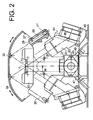
- Fig. 2 a detailed view, partly as seen in a sectional view, through a fiber welding device is shown, particularly intended for welding optical fiber ribbons, in which the view/the section is taken substantially centrally through the device and the view is seen in parallel to and the sectional views are taken perpendicularly to the direction of the fibers which are to be welded to each other.
- the principle of background illumination is applied, which has being described above.
- the components of the device are carried by an elongated frame bar 43 having a longitudinal direction coinciding with the fiber direction and having a rectangular cross-section, which is supported by a base 45 through four oblique legs 47.
- the legs 47 can comprise elastic, cushioning intermediate pieces such as 49.
- the central frame 51 Centrally on the frame bar 43 a central frame 51 is attached and projects therefrom.
- the central frame 51 has generally an isosceles triangular shape having its point between the two equal legs directed downwards towards the frame bar 43 and comprising a substantially horizontal and flat top surface and further comprising two symmetrically placed projections or triangular halves 55. They project perpendicularly to the direction of the fibers and are cut-off at their triangular points forming surfaces, which are located in straight angles to the oblique sides of the triangular shape.
- the projections 55 carry light sources and cameras, see hereinafter.
- the horizontal top surface of the central frame 51 comprises an electrode house 57 to which parts, not shown, are attached, which are required for retaining the ends of the fibers and for the alignment thereof with each other, and further the welding electrodes 11.
- oblique cylindrical through-holes 59 are provided which extend in parallel to the exterior cut-off sides of the projections and the axes of which are located in a vertical transverse plane in which also the end surfaces of the fibers to be spliced to each other are located.
- the axes of the holes 59 and the exterior cut-off surfaces 55 are located in an angle between 30 and 45° in relation to a vertical plane, in the preferred case in an angle between 35 and 40° and preferably about 37°.
- light passes from light sources 23 such as from light emitting diodes 21 mounted in the bottom ends of the holes.
- Light from the light emitting diodes 21' passes in the circular cylindrical holes 59 towards the upper ends thereof but are first reduced in intensity by diaphragms, which together with the walls of the holes 59 are formed by plates 27', which perpendicularly project into the interior of the holes 59 and are arranged in slots in the central frame 51 at a distance from the upper openings thereof, which is approximately as large as the diameter of the holes 59.
- the diaphragm plates 27' have a straight inner or lower edge and projects in to about the centre of the holes 59, so that the light is allowed to pass through an approximately semi-circular aperture.
- the same resulting aperture is obtained, which is obtained by using a diaphragm 27 having a semi-circular aperture of the design illustrated in Fig. 1c.
- light scattering or diffusing means 29 are located such as suitable gratings in order to achieve a uniform, diffuse background illumination.
- Camera units 61 are with their front portions inserted in corresponding holes in the oblique surfaces of the inverted triangular shape of the central frame 51.
- the camera units 61 have a front portion 63, which contains their optical system.
- the optical axes of the optical systems are parallel to the axes of the holes 59 and extend through the longitudinal axis of the fibers or fiber ribbons, which are to be spliced to each other exactly in the splicing plane.
- the continuations of the holes for the camera unit 61 extend up to the bottom side of the electrode housing 57 in order for light from the splicing region of the fibers being imaged by the optical systems on the light sensitive elements of the camera unit 61, the light sensitive elements being located at the plane 65 and arranged in an oblique angle and not perpendicularly to the axes of the optical systems, the angle being adapted to give a sharp picture of all different fibers in fiber ribbons, which are to be spliced.
- the top portion of the central frame 51 and the electrode housing 57 is protected by two casing halves 69, which are mounted to be capable of swinging towards and from each other about shafts 67.
- the mirrors 25 are arranged having horizontal reflecting surfaces, which are placed, so that light rays from the diffusing elements 29 can be mirrored therein and reflected, so that they can enter the optical systems of the camera units 61 and be conducted thereby towards the light sensitive surfaces in the camera units.
Landscapes
- Physics & Mathematics (AREA)
- Engineering & Computer Science (AREA)
- Plasma & Fusion (AREA)
- General Physics & Mathematics (AREA)
- Optics & Photonics (AREA)
- Mechanical Coupling Of Light Guides (AREA)
- Instruments For Viewing The Inside Of Hollow Bodies (AREA)
- Microscoopes, Condenser (AREA)
- Treatment Of Fiber Materials (AREA)
Description
- The present invention relates to a method and a device for illuminating, when imaging the end region of a cut-off optical fiber ribbon, in particular in conjunction with splicing the fiber ribbon to another fiber ribbon by means of welding, the area intended to be imaged.
- In order to measure, in a fiber ribbon welding device, various geometrical quantities such as fiber gap, fiber diameter, offset laterally between the exterior sides of the fibers and between the cores of the fibers, etc., of the fibers to be welded to each other the positions of the fibers in the xyz-coordinate system of the device must be determined. In order to make it the ends of the fibers must be observed in two different directions or equivalently two pictures must be taken in two such directions. These directions must then be placed obliquely in relation to a plane through the end portions of the fiber ribbons, most preferably in directions of about 45° to this plane, so that the two directions have an angle of about 90° to each other, in order to obtain the largest possible information on the positions of the fibers. In the imaging operation then thus the very object, i.e. the end portions of the fiber ribbons, is located obliquely, having some parts located more distant from and other parts at a shorter distance from the opening of a lens system which is included in the camera, by means of which such a picture is usually made. It causes in turn a varying magnification in the picture captured by the camera and thereby a varying light intensity in the picture. The varying light intensity in the picture is particularly embarrassing as to the generally used light background, which gives difficulties when measuring on all of the picture field and when adjusting the camera in order to obtain a maximal sensitivity in regard of the determination of the position of the outlines of the ends of the different fibers in relation to each other in one single picture.
- Systems for achieving a more uniform incoming light intensity to different devices are known from for example U.S. patents US-A 5,442,414 and US-A 4,391,521 and from the published British patent application GB-A 2 226 145.
- An apparatus for splicing optical fiber ribbons including oblique illumination of the ribbons is known from EP-0 720 032-A1. A method comprising oblique illumination of fiber arrays is disclosed in JP-02-037306.
- It is an object of the invention to provide a method and a device as defined in claims 1 and 7, respectively.
- When welding optical fiber ribbons in a fiber welding machine an object is imaged, which is constituted by the end portions of the fiber ribbons, by means of a lens system on a light sensitive surface. Since two such pictures must be captured in approximately perpendicular directions in order to determine the position of the object in all dimensions accurately, i.e. the position of the fiber ends for example both in a height direction and in their longitudinal direction, the optical axis in each picture must be located obliquely in relation to a plane passing through the outlines of the very object, i.e. through the end portions of the fiber ribbons. By the term that a position is oblique is here meant that it deviates substantially both from a parallel and a perpendicular position and thus also an oblique angle is an angle which deviates substantially from being equal to 0° or equal to 90°. The oblique position of the object in the imaging operation implies that the magnification of the end portions of the different fibers becomes different and thereby also the background illumination becomes different. The contrast in a picture captured of such an obliquely located object will then vary in the different portions of the picture, which show the ends of the different fibers which are included in the fiber ribbons. In order to produce a uniform background illumination a light source is placed, as seen from the lens system, behind the end portions, which form the object to be depicted. Between the light source and the object a diaphragm is arranged, which is asymmetric and is designed to have a non-circular aperture, in particular a non-rotationally symmetrical or a non-centrosymmetrical aperture, and which instead for example has the shape of a circular segment such as a semi-circle or a symmetric trapezoid. In order to further improve the background illumination a light diffusing plate can be placed between the diaphragm and the object.
- Thus, a method and device is concerned with producing a background illumination when imaging an object having outlines located substantially in a single plane. The object is formed by end portions of optical fiber ribbons placed opposite each other in a fiber welding device. A light source provides, as seen in a direction, a light beam having substantially a uniform or homogenous intensity in this direction. The light beam thus comprises light rays which have substantially the same intensity and distributed substantially rotationally symmetrically around a centre direction. Such a light beam is easily produced by conducting light from a conventional light source through a straight channel or bore. The light source and the light beam are arranged, so that the centre direction of the light beam passes through and/or at the object and hits the backside or rear side of the object in an oblique angle, e.g. between 45 and 60°, in particular between 45 and 55°, in relation to a plane, which extends substantially through the outlines of the object. The light source is preferably placed, so that the centre direction extends substantially centrally through an opening of and/or in parallel to an optical axis of an imaging lens system.
- Before hitting the object the intensity of the light beam is asymmetrically reduced in a particular way. The reduction is made so that less light rays hit the region of the object which is closest as seen in the light beam direction than more distantly located regions or so that, in the plane through the object, the intensity of light originating from the light source is smaller in the closest regions of the object plane than in distant regions, as counted from the light source.
- The reduction of light intensity is produced by an asymmetric diaphragm, placed between the light source and the object. The diaphragm can then have an aperture, which has the shape of a segment of a circle such as a semi-circle or a symmetric trapezoid. In the case where the light beam is produced by conducting light in a channel having a circular uniform cross-section the reduction of intensity is preferably made by a diaphragm plate projecting in to the channel. Before hitting the object and after being reduced in intensity the light of the light beam can be scattered or diffused by suitable means, such as a light scattering or diffusing plate.
- Additional objects and advantages of the invention will be set forth in the description which follows, and in part will be obvious from the description, or may be learned by practice of the invention. The objects and advantages of the invention may be realized and obtained by means of the method and and device as defined in the appended claims.
- While the novel features of the invention are defined in the appended claims, a complete understanding of the invention, both as to organization and content, and of the above and other features thereof may be gained from and the invention will be better appreciated from a consideration of the following detailed description of non-limiting embodiments presented hereinbelow with reference to the accompanying drawings, in which:
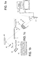
- Fig. 1a is a schematic picture showing a fiber ribbon welding device comprising an optical system for imaging end regions of fiber ribbons inserted in the device,
- Fig. 1b is a view of an aperture having a trapezoid shape,
- Fig. 1c is a view of an aperture having a semi-circular shape, and
- Fig. 2 is a side view of a fiber welding device as seen in the longitudinal direction of the fiber ribbons.
- In Fig. 1a a method of arranging a background illumination in a fiber splicing device is schematically illustrated. The fiber splicing device is intended for splicing optical fiber ribbons and comprises an optical system for imaging end portions of the fiber ribbons to be spliced, in order to display pictures thereof on a display monitor. The cross-sections of the individual optical fibers kept together to form a fiber ribbon are shown at 1, since the fibers are assumed to be located perpendicularly to the plane of the paper in Fig. 1a. In order to weld the fiber ends to each
other electrodes 11 are arranged, which are connected to a high-voltage source, not shown, and which have longitudinal directions perpendicular to the fibers 1. When making the welding the end surfaces of the fibers are placed in a suitable way in relation to the points of theelectrodes 11 and then between the points an electric arc is formed, which heats the end regions of the fibers and welds them to other fibers, not shown, also suitably kept together to form a fiber ribbon. - In order to determine the positions of the fibers and in particular the positions of their end surfaces and possibly other parameters of the fiber ends cameras are used, one of which being shown at 13 and which each comprise a
lens system 15. Thelens system 15 is arranged to have its optical axis located obliquely to the plane, which extends through the end regions of the fibers 1, so that the axis forms an acute angle α to this plane. When two cameras are used, they are symmetrically located in relation to the region, in which the welding is to be performed. In particular the optical axes of the two cameras can be assumed to be located in the same vertical plane as seen in Fig. 1a, perpendicularly to the longitudinal direction of the fiber ends. The axes should most preferably be located perpendicularly to each other in order to provide the largest possible information in regard of the positions of the fiber ends. This results in an angle α of 45°. It can be difficult to practically obtain such an angle in an actual welding device, in which a lot of further devices are provided, among other things devices providing a background illumination, as will be described hereinafter. However, an angle α of 45 - 60°, e.g. within the interval of 45 - 55°, generally gives sufficiently good information. - The
camera 13 furthermore compriseslight detectors 17 including a set of light sensitive elements, for example CCD-elements, arranged in a single plane. The light sensitive elements are connected to an electronicimage processing unit 19 and therethrough to adisplay monitor 21, so that the picture captured can be displayed on the monitor. Since the end regions of the fibers 1 are not located perpendicularly to the optical axes of thecameras 13, the pictures of fiber ends produced by means of thelens systems 15 are not located in a plane perpendicular to the respective optical axis but they are located in a plane, which forms an angle β thereto. The plane of the pictures coincide with the plane of the light sensitive elements in thelight detector 17, as is described in detail in the simultaneously filed patent application having the title "Imaging optical fiber ribbons". - In the picture obtained by the optical system thus described the positions of the fiber ends appear from the positions of the outlines of the pictures of the individual fiber ends, which are determined by the
image processing unit 19. The contours or outlines are formed by the contrast between the very picture of a fiber end and the picture of the light background. If a constant background illumination is used, the light intensity in the image plane at thelight detector 17 is different in different regions of the picture, not considering the relatively small areas in the picture which are the direct pictures of the very fiber ends. The varying light intensity depends on the varying magnification in the different parts of the picture, which in turn results from the fact that the optical system comprises oblique object and image planes. The non-uniform background light intensity causes problems in measurements on the picture and in the automatic image processing in theunit 19. For example, thecamera 13 is generally provided with a built-in automatic gain control, which automatically reduces the sensitivity of the light detector for a too large light intensity in some part of the picture. It can result in that the sensitivity is so much reduced that it for example in an automatic image processing becomes difficult to determine the boundary lines between a picture of the fiber end, at which the background light intensity is smallest. Also the picture of the end regions of the fibers, which is generated on adisplay monitor 21, obtains different light grades in its different parts, which makes it more difficult for an operator to evaluate this picture when directly looking at it. - In the welding device a background illumination is arranged by placing a
light source 23 such as a light emitting diode generally in a direction straightly behind the fiber ends 1 as seen from thelens system 15 of thecamera 13. In the case illustrated in Fig. 1a the light from the light source is deflected by aflat mirror 25 placed at a suitable location, for example having its mirror plane parallel to the plane through the fiber ends 1. In the path of the light rays from thelight source 23 and themirror 25 and thus between the light source and the objects which are to be imaged, i.e. the fiber ends 1, adiaphragm 27 is provided, which can for example comprise a flat, non-transparent plate having an opening therein. Between thediaphragm 27 and the mirror 25 a light scattering or diffusingplate 29 is provided having the shape of a suitable grating. The opening in theaperture 27 is then designed, for example having a suitable symmetrical trapezoid shape, as is indicated in Fig. 1b, so that the picture of the background illumination in the image plane through thelight detector 17 has a substantially constant light intensity. - In Fig. 2 a detailed view, partly as seen in a sectional view, through a fiber welding device is shown, particularly intended for welding optical fiber ribbons, in which the view/the section is taken substantially centrally through the device and the view is seen in parallel to and the sectional views are taken perpendicularly to the direction of the fibers which are to be welded to each other. In this device the principle of background illumination is applied, which has being described above. The components of the device are carried by an
elongated frame bar 43 having a longitudinal direction coinciding with the fiber direction and having a rectangular cross-section, which is supported by a base 45 through fouroblique legs 47. Thelegs 47 can comprise elastic, cushioning intermediate pieces such as 49. Centrally on the frame bar 43 acentral frame 51 is attached and projects therefrom. Thecentral frame 51 has generally an isosceles triangular shape having its point between the two equal legs directed downwards towards theframe bar 43 and comprising a substantially horizontal and flat top surface and further comprising two symmetrically placed projections ortriangular halves 55. They project perpendicularly to the direction of the fibers and are cut-off at their triangular points forming surfaces, which are located in straight angles to the oblique sides of the triangular shape. Theprojections 55 carry light sources and cameras, see hereinafter. - The horizontal top surface of the
central frame 51 comprises anelectrode house 57 to which parts, not shown, are attached, which are required for retaining the ends of the fibers and for the alignment thereof with each other, and further thewelding electrodes 11. At the exterior sides of theprojections 55 oblique cylindrical through-holes 59 are provided which extend in parallel to the exterior cut-off sides of the projections and the axes of which are located in a vertical transverse plane in which also the end surfaces of the fibers to be spliced to each other are located. The axes of theholes 59 and the exterior cut-offsurfaces 55 are located in an angle between 30 and 45° in relation to a vertical plane, in the preferred case in an angle between 35 and 40° and preferably about 37°. In theholes 59 light passes fromlight sources 23 such as from light emittingdiodes 21 mounted in the bottom ends of the holes. - Light from the light emitting diodes 21' passes in the circular
cylindrical holes 59 towards the upper ends thereof but are first reduced in intensity by diaphragms, which together with the walls of theholes 59 are formed by plates 27', which perpendicularly project into the interior of theholes 59 and are arranged in slots in thecentral frame 51 at a distance from the upper openings thereof, which is approximately as large as the diameter of theholes 59. The diaphragm plates 27' have a straight inner or lower edge and projects in to about the centre of theholes 59, so that the light is allowed to pass through an approximately semi-circular aperture. The same resulting aperture is obtained, which is obtained by using adiaphragm 27 having a semi-circular aperture of the design illustrated in Fig. 1c. At the top openings of theholes 59 light scattering or diffusing means 29 are located such as suitable gratings in order to achieve a uniform, diffuse background illumination. -
Camera units 61 are with their front portions inserted in corresponding holes in the oblique surfaces of the inverted triangular shape of thecentral frame 51. Thecamera units 61 have afront portion 63, which contains their optical system. The optical axes of the optical systems are parallel to the axes of theholes 59 and extend through the longitudinal axis of the fibers or fiber ribbons, which are to be spliced to each other exactly in the splicing plane. The continuations of the holes for thecamera unit 61 extend up to the bottom side of theelectrode housing 57 in order for light from the splicing region of the fibers being imaged by the optical systems on the light sensitive elements of thecamera unit 61, the light sensitive elements being located at theplane 65 and arranged in an oblique angle and not perpendicularly to the axes of the optical systems, the angle being adapted to give a sharp picture of all different fibers in fiber ribbons, which are to be spliced. - The top portion of the
central frame 51 and theelectrode housing 57 is protected by two casinghalves 69, which are mounted to be capable of swinging towards and from each other about shafts 67. At the interior side of the casings, at the topmost portions thereof including approximately horizontal surfaces themirrors 25 are arranged having horizontal reflecting surfaces, which are placed, so that light rays from the diffusingelements 29 can be mirrored therein and reflected, so that they can enter the optical systems of thecamera units 61 and be conducted thereby towards the light sensitive surfaces in the camera units.
Claims (18)
- A method of producing a background illumination in an optical fiber splicing device for end regions of optical fibers (1) in fiber ribbons to be spliced to each other when imaging the end regions through a lens system (15) on an imaging unit (13, 61), said end regions forming an object having outlines located substantially in a single plane located at an oblique angle (α) to the optical axis of the lens system (15) and the imaging unit (13, 61), the method including the steps of:- producing (23; 21', 59) a light beam having substantially a homogenous intensity distributed substantially rotationally symmetrically about a centre direction coinciding with said optical axis, the light beam directed at a rear side of the object, as seen from the imaging unit (13, 61), at said oblique angle (α) to said single plane,the method being characterized by- reducing asymmetrically the intensity of light beam by making it pass through an asymmetric diaphragm and then scattering or diffusing (29) it before it hits the object, so that less light rays hit the most adjacent region of the object as seen in the direction of the light beam than more distant regions to make regions of the object, which are located closer to the imaging unit (13, 61) have a stronger background illumination than regions of the object which are located more distantly in relation to the imaging unit to obtain, considering the magnification of the lens system (15), a picture in the imaging unit (13, 61) of the background illumination having a substantially constant light intensity.
- A method according to claim 1, characterized in that the oblique angle is between 45 and 60°.
- A method according to any of claims 1 - 2, characterized in that the oblique angle is between 45 and 55°.
- A method according to any of claims 1 - 3, characterized in that in the scattering or diffusing of the light beam, the light beam is made to pass a light scattering or diffusing plate (29).
- A method according to any of claims 1 - 4, characterized in that in the step of producing a light beam, the light beam is produced by conducting light from a light source element (21') through a straight channel or bore (59).
- A method according to claim 5, characterized in that in the step of reducing asymmetrically the intensity of light beam, the light beam is made to pass a diaphragm formed by walls of the channel or bore (59) and a plate (27'), which perpendicularly projects into the interior of the channel or bore (59).
- An optical fiber splicing device for splicing ends of optical fibers in two fiber ribbons to each other including- a lens system (15) and an imaging unit (13, 61) having an optical axis for imaging end regions of said ends through a lens system (15) on an imaging unit (13, 61), said end regions forming an object having outlines located substantially in a single plane located at an oblique angle (α) to said optical axis, and- a background illumination device for producing a background illumination when imaging the end regions through the lens system (15) on the imaging unit (13, 61), the background illumination device comprising- - a light source (23; 21', 59), which provides a light beam having a substantially homogenous intensity distributed substantially rotationally symmetrically about a centre direction coinciding with said optical axis, the light source (23; 21', 59) arranged so that the light beam hits the rear side of the object, as seen from the imaging unit, at said oblique angle (α) to said single plane, to pass through and/or at the object;the fiber splicing device being characterized by the background illumination device having- - an asymmetric diaphragm (27; 27', 59) placed between the light source (23; 21', 59) and the object, and-- a light scattering or diffusing means (29) placed between the diaphragm and the object for scattering of diffusing the light beam after passing the diaphragm, the diaphragm (27; 27', 59) and the light scattering or diffusing means (29) arranged to asymmetrically reduce the intensity of the light beam, so that less light rays hit the most adjacent region of the object as seen in the direction of the light beam than more distant regions to make regions of the object, which are located closer to the imaging unit (13, 61) have a stronger background illumination than regions of the object which are located more distantly in relation to the imaging unit (13, 61) to obtain, when imaging the object on the imaging unit (13, 61) and considering the magnification of the lens system (15), a picture in the imaging unit (13, 61) of the background illumination that has a substantially constant light intensity.
- A device according to claim 7, characterized in that the light scattering or diffusing means is a light scattering or diffusing plate (29).
- A device according to any of claims 7 - 8, characterized in that the oblique angle (α) is between 45 and 60°.
- A device according to any of claims 7 - 9, characterized in that the oblique angle (α) is between 45 and 55°.
- A device according to any of claims 7 - 10, characterized in that the diaphragm is a diaphragm plate having an aperture (27).
- A device according to claim 11, characterized in that the aperture (27) has the shape of a circular segment.
- A device according to claim 11, characterized in that the aperture (27) has the shape of a semi-circle.
- A device according to claim 11, characterized in that the aperture (27) has the shape of a symmetric trapezoid.
- A device according to any of claims 7 - 15, characterized in that the light source includes a light source element (21') mounted in the bottom end of a straight channel or bore (59).
- A device according to claim 15, characterized in that the straight channel or bore (59) is a circular cylindrical hole.
- A device according to claim 15 or 16, characterized in that the diaphragm is formed by walls of a straight channel or bore (59) and a plate (27'), which perpendicularly projects into the straight channel or bore (59).
- A device according to claim 17, characterized in that the plate (27') has a straight inner or lower edge and projects in to substantially the centre of the straight channel or bore (59), so that light from the light source element (21') is allowed to pass a substantially semi-circular aperture (27).
Applications Claiming Priority (2)
| Application Number | Priority Date | Filing Date | Title |
|---|---|---|---|
| SE9701952A SE509712C2 (en) | 1997-05-23 | 1997-05-23 | Method and apparatus for providing a backlight when imaging an object. |
| SE9701952 | 1997-05-23 |
Publications (2)
| Publication Number | Publication Date |
|---|---|
| EP0889340A1 EP0889340A1 (en) | 1999-01-07 |
| EP0889340B1 true EP0889340B1 (en) | 2007-05-02 |
Family
ID=20407075
Family Applications (1)
| Application Number | Title | Priority Date | Filing Date |
|---|---|---|---|
| EP98850080A Expired - Lifetime EP0889340B1 (en) | 1997-05-23 | 1998-05-19 | Splicing device for optical fiber ribbons with fiber background illumination and corresponding method |
Country Status (5)
| Country | Link |
|---|---|
| US (1) | US6002486A (en) |
| EP (1) | EP0889340B1 (en) |
| JP (1) | JP4468496B2 (en) |
| DE (1) | DE69837695T2 (en) |
| SE (1) | SE509712C2 (en) |
Families Citing this family (1)
| Publication number | Priority date | Publication date | Assignee | Title |
|---|---|---|---|---|
| JP4258912B2 (en) * | 1999-09-30 | 2009-04-30 | 住友電気工業株式会社 | Optical waveguide positioning member and positioning method |
Citations (2)
| Publication number | Priority date | Publication date | Assignee | Title |
|---|---|---|---|---|
| JPH0237306A (en) * | 1988-07-27 | 1990-02-07 | Fujikura Ltd | Method of inspecting juncture of multiple optical fiber |
| EP0720032A1 (en) * | 1994-12-29 | 1996-07-03 | Sumitomo Electric Industries, Ltd. | Apparatus for splicing optical fibers and method |
Family Cites Families (3)
| Publication number | Priority date | Publication date | Assignee | Title |
|---|---|---|---|---|
| JPS5643628A (en) * | 1979-09-18 | 1981-04-22 | Olympus Optical Co Ltd | Photodetecting device which eliminates asymmetric lighting of photodetector |
| US4908677A (en) * | 1987-08-14 | 1990-03-13 | Fujikura Ltd. | Method of examining the states of alignment of glass fibers of a pair of ribbon fiber cables |
| US4863275A (en) * | 1988-04-20 | 1989-09-05 | Ball Corporation | Portable, shock-proof container surface profiling instrumentation |
-
1997
- 1997-05-23 SE SE9701952A patent/SE509712C2/en not_active IP Right Cessation
-
1998
- 1998-05-19 EP EP98850080A patent/EP0889340B1/en not_active Expired - Lifetime
- 1998-05-19 DE DE69837695T patent/DE69837695T2/en not_active Expired - Lifetime
- 1998-05-22 US US09/082,966 patent/US6002486A/en not_active Expired - Lifetime
- 1998-05-25 JP JP14332698A patent/JP4468496B2/en not_active Expired - Fee Related
Patent Citations (2)
| Publication number | Priority date | Publication date | Assignee | Title |
|---|---|---|---|---|
| JPH0237306A (en) * | 1988-07-27 | 1990-02-07 | Fujikura Ltd | Method of inspecting juncture of multiple optical fiber |
| EP0720032A1 (en) * | 1994-12-29 | 1996-07-03 | Sumitomo Electric Industries, Ltd. | Apparatus for splicing optical fibers and method |
Also Published As
| Publication number | Publication date |
|---|---|
| DE69837695T2 (en) | 2008-01-10 |
| SE509712C2 (en) | 1999-03-01 |
| JPH10334716A (en) | 1998-12-18 |
| JP4468496B2 (en) | 2010-05-26 |
| US6002486A (en) | 1999-12-14 |
| SE9701952D0 (en) | 1997-05-23 |
| SE9701952L (en) | 1998-11-24 |
| DE69837695D1 (en) | 2007-06-14 |
| EP0889340A1 (en) | 1999-01-07 |
Similar Documents
| Publication | Publication Date | Title |
|---|---|---|
| JP5636413B2 (en) | Method and apparatus for visualizing signature marks on spectacle lenses | |
| JP3133430B2 (en) | Apparatus and method for detecting hidden marks on progressive aspheric spectacle lenses | |
| US6359694B1 (en) | Method and device for identifying the position of an electrical component or terminals thereof, and equipping head employing same | |
| EP0889340B1 (en) | Splicing device for optical fiber ribbons with fiber background illumination and corresponding method | |
| US4878933A (en) | Apparatus for fusion splicing optical fibers | |
| JPH1190625A (en) | Welding equipment for shielded optical fiber | |
| US6067397A (en) | Method and device for producing a sharp picture of an end region of an optical fiber ribbon | |
| US4681453A (en) | Optoelectronic comparison apparatus for structures on plane surfaces or for planar structures | |
| US5666204A (en) | Method and apparatus for optical shape measurement of oblong objects | |
| JP2000019382A (en) | Focus detection unit mounting structure | |
| KR102821157B1 (en) | Test apparatus and test method | |
| CN221745478U (en) | A galvanometer light-deficient detection device | |
| US4496231A (en) | Mirror reflex camera with exposure meter | |
| CN119756240B (en) | Lens installation precision measuring system and lens installation precision measuring method | |
| JPH09257643A (en) | Lens meter | |
| CN212722577U (en) | Optical imaging device and optical imaging equipment | |
| US4451143A (en) | Combination direct/reverse image copy machine | |
| CN119756241A (en) | A lens installation accuracy measurement system and a lens installation accuracy measurement method | |
| JP3224859B2 (en) | Surface shape inspection system for convex lenses | |
| JP2904567B2 (en) | Finder device | |
| EP3722792A1 (en) | Illumination for web imaging | |
| JPH0648178B2 (en) | Optical axis adjusting device and optical axis adjusting method | |
| JPS5810709A (en) | Optical system of automatic focus detection device | |
| ITRM970228U1 (en) | DEVICE FOR MEASURING THE TRANSMISSION OF OPTICAL LENSES | |
| KR20020092485A (en) | Projection lens unit for projector |
Legal Events
| Date | Code | Title | Description |
|---|---|---|---|
| PUAI | Public reference made under article 153(3) epc to a published international application that has entered the european phase |
Free format text: ORIGINAL CODE: 0009012 |
|
| AK | Designated contracting states |
Kind code of ref document: A1 Designated state(s): DE FR GB IT |
|
| AX | Request for extension of the european patent |
Free format text: AL;LT;LV;MK;RO;SI |
|
| 17P | Request for examination filed |
Effective date: 19990707 |
|
| AKX | Designation fees paid |
Free format text: DE FR GB IT |
|
| RAP1 | Party data changed (applicant data changed or rights of an application transferred) |
Owner name: TELEFONAKTIEBOLAGET LM ERICSSON (PUBL) |
|
| 17Q | First examination report despatched |
Effective date: 20040908 |
|
| GRAP | Despatch of communication of intention to grant a patent |
Free format text: ORIGINAL CODE: EPIDOSNIGR1 |
|
| RIC1 | Information provided on ipc code assigned before grant |
Ipc: G02B 6/255 20060101AFI20061108BHEP |
|
| RTI1 | Title (correction) |
Free format text: SPLICING DEVICE FOR OPTICAL FIBER RIBBONS WITH FIBER BACKGROUND ILLUMINATION AND CORRESPONDING METHOD |
|
| GRAS | Grant fee paid |
Free format text: ORIGINAL CODE: EPIDOSNIGR3 |
|
| GRAA | (expected) grant |
Free format text: ORIGINAL CODE: 0009210 |
|
| AK | Designated contracting states |
Kind code of ref document: B1 Designated state(s): DE FR GB IT |
|
| REG | Reference to a national code |
Ref country code: GB Ref legal event code: FG4D |
|
| REF | Corresponds to: |
Ref document number: 69837695 Country of ref document: DE Date of ref document: 20070614 Kind code of ref document: P |
|
| ET | Fr: translation filed | ||
| PLBE | No opposition filed within time limit |
Free format text: ORIGINAL CODE: 0009261 |
|
| STAA | Information on the status of an ep patent application or granted ep patent |
Free format text: STATUS: NO OPPOSITION FILED WITHIN TIME LIMIT |
|
| 26N | No opposition filed |
Effective date: 20080205 |
|
| PG25 | Lapsed in a contracting state [announced via postgrant information from national office to epo] |
Ref country code: IT Free format text: LAPSE BECAUSE OF FAILURE TO SUBMIT A TRANSLATION OF THE DESCRIPTION OR TO PAY THE FEE WITHIN THE PRESCRIBED TIME-LIMIT Effective date: 20070502 |
|
| PGFP | Annual fee paid to national office [announced via postgrant information from national office to epo] |
Ref country code: GB Payment date: 20130528 Year of fee payment: 16 Ref country code: DE Payment date: 20130530 Year of fee payment: 16 |
|
| PGFP | Annual fee paid to national office [announced via postgrant information from national office to epo] |
Ref country code: FR Payment date: 20130606 Year of fee payment: 16 |
|
| REG | Reference to a national code |
Ref country code: DE Ref legal event code: R119 Ref document number: 69837695 Country of ref document: DE |
|
| GBPC | Gb: european patent ceased through non-payment of renewal fee |
Effective date: 20140519 |
|
| REG | Reference to a national code |
Ref country code: DE Ref legal event code: R119 Ref document number: 69837695 Country of ref document: DE Effective date: 20141202 |
|
| REG | Reference to a national code |
Ref country code: FR Ref legal event code: ST Effective date: 20150130 |
|
| PG25 | Lapsed in a contracting state [announced via postgrant information from national office to epo] |
Ref country code: DE Free format text: LAPSE BECAUSE OF NON-PAYMENT OF DUE FEES Effective date: 20141202 |
|
| PG25 | Lapsed in a contracting state [announced via postgrant information from national office to epo] |
Ref country code: GB Free format text: LAPSE BECAUSE OF NON-PAYMENT OF DUE FEES Effective date: 20140519 Ref country code: FR Free format text: LAPSE BECAUSE OF NON-PAYMENT OF DUE FEES Effective date: 20140602 |