EP0889334A1 - Sensor device based on retroreflection of a laser beam - Google Patents
Sensor device based on retroreflection of a laser beam Download PDFInfo
- Publication number
- EP0889334A1 EP0889334A1 EP98108776A EP98108776A EP0889334A1 EP 0889334 A1 EP0889334 A1 EP 0889334A1 EP 98108776 A EP98108776 A EP 98108776A EP 98108776 A EP98108776 A EP 98108776A EP 0889334 A1 EP0889334 A1 EP 0889334A1
- Authority
- EP
- European Patent Office
- Prior art keywords
- triples
- triple
- cube
- retroflector
- full
- Prior art date
- Legal status (The legal status is an assumption and is not a legal conclusion. Google has not performed a legal analysis and makes no representation as to the accuracy of the status listed.)
- Granted
Links
- 241000264877 Hippospongia communis Species 0.000 description 29
- 230000005540 biological transmission Effects 0.000 description 5
- 230000011514 reflex Effects 0.000 description 5
- 238000011156 evaluation Methods 0.000 description 4
- 238000000034 method Methods 0.000 description 4
- 239000011521 glass Substances 0.000 description 3
- 230000010287 polarization Effects 0.000 description 3
- 230000004888 barrier function Effects 0.000 description 2
- 230000007423 decrease Effects 0.000 description 2
- 238000005516 engineering process Methods 0.000 description 2
- 230000007794 irritation Effects 0.000 description 2
- 238000004519 manufacturing process Methods 0.000 description 2
- 239000002184 metal Substances 0.000 description 2
- 239000004033 plastic Substances 0.000 description 2
- 230000008569 process Effects 0.000 description 2
- 230000001953 sensory effect Effects 0.000 description 2
- 229910000679 solder Inorganic materials 0.000 description 2
- 238000001228 spectrum Methods 0.000 description 2
- 206010016654 Fibrosis Diseases 0.000 description 1
- 229910000831 Steel Inorganic materials 0.000 description 1
- 230000002411 adverse Effects 0.000 description 1
- 238000004364 calculation method Methods 0.000 description 1
- 230000008859 change Effects 0.000 description 1
- 230000007882 cirrhosis Effects 0.000 description 1
- 208000019425 cirrhosis of liver Diseases 0.000 description 1
- 238000005520 cutting process Methods 0.000 description 1
- 238000009826 distribution Methods 0.000 description 1
- 238000004868 gas analysis Methods 0.000 description 1
- 230000006872 improvement Effects 0.000 description 1
- 230000002262 irrigation Effects 0.000 description 1
- 238000003973 irrigation Methods 0.000 description 1
- 230000003287 optical effect Effects 0.000 description 1
- 239000003973 paint Substances 0.000 description 1
- 230000005855 radiation Effects 0.000 description 1
- 230000009467 reduction Effects 0.000 description 1
- 239000010959 steel Substances 0.000 description 1
- 230000007704 transition Effects 0.000 description 1
Images


Classifications
-
- G—PHYSICS
- G02—OPTICS
- G02B—OPTICAL ELEMENTS, SYSTEMS OR APPARATUS
- G02B5/00—Optical elements other than lenses
- G02B5/12—Reflex reflectors
- G02B5/122—Reflex reflectors cube corner, trihedral or triple reflector type
- G02B5/124—Reflex reflectors cube corner, trihedral or triple reflector type plural reflecting elements forming part of a unitary plate or sheet
-
- G—PHYSICS
- G01—MEASURING; TESTING
- G01D—MEASURING NOT SPECIALLY ADAPTED FOR A SPECIFIC VARIABLE; ARRANGEMENTS FOR MEASURING TWO OR MORE VARIABLES NOT COVERED IN A SINGLE OTHER SUBCLASS; TARIFF METERING APPARATUS; MEASURING OR TESTING NOT OTHERWISE PROVIDED FOR
- G01D5/00—Mechanical means for transferring the output of a sensing member; Means for converting the output of a sensing member to another variable where the form or nature of the sensing member does not constrain the means for converting; Transducers not specially adapted for a specific variable
- G01D5/26—Mechanical means for transferring the output of a sensing member; Means for converting the output of a sensing member to another variable where the form or nature of the sensing member does not constrain the means for converting; Transducers not specially adapted for a specific variable characterised by optical transfer means, i.e. using infrared, visible, or ultraviolet light
Definitions
- the invention relates to a sensor device based on retroreflection of a laser beam.
- the aim of this sensor device is for retroreflection and polarization rotation based laser sensor technology is easy in practice to create a manageable retroflective surface that is sharply contoured Laser signal for evaluation delivers and thus much better, high-resolution Fine scanning enabled.
- DE 42 40 680 A1 describes a process for the production of structured microtripel reflex surfaces described, according to which the retroreflective microtriples are cube-like and have a diameter from 0.002 mm to 0.8 mm and combined in groups of the same microtriples where the diameter of the groups is less than 7 mm and at least two groups and / or more is the reflective surface form.
- a reflector is described in JP 6-273608, Patent abstracts of Japan, which has a high reflection efficiency by forming a Plurality of cube corners, in the mixed state on the reflection surface and arranged with different formats.
- the sensors are based on retroreflection and polarization rotation Laser sensor systems e.g. B. known as reflex light barriers. This reflex light barriers working with laser light and polarization filter are used with retroreflectors. There are also retroreflectors large format, expensive glass triple, concave mirror made of metal and conventional triple reflectors made of glass or plastic. The beam interruption of the retroreflected beam between the retroreflector and The transmitter / receiver is interpreted as a binary signal.
- the laser beam In order to avoid errors in the signal evaluation, the laser beam often additionally polarized and / or pulsed and / or to certain light spectra limited.
- Such undesirable reflection rays form e.g. B. in observation of glass bodies in a bottle filling system.
- Reflections on metal, paint or plastic surfaces e.g. B. in the sensory observation of parcels in the parcel distribution, in Conveyors, in the sensory scanning of motor vehicles in Car washes.
- the fine resolution of the reflex sensor system depends on the Retroreflector a sharply contoured, one that cannot be confused with external radiation Receives signal.
- the sensor device according to the invention is intended to be an essential one Improvement of the fine scanning of the sensor system through exact redirection of the laser beam in the retroflector and return of a sharp contour Signal are caused.
- the retroflector should consist of one surface, many small triple consist. The smaller the triple, the smaller is also the annoying beam offset between incoming and outgoing light beam.
- Retroflexion body suggested the cube-shaped full cube, or Perkin-Elmer pyramid called. Its rectangular Reflection surfaces are at about 90 ° to each other.
- the pyramidal is not suitable Triple, which is just a cube corner section.
- the reflection surfaces of the pyramidal triple are triangular. Are on you Subareas during beam deflection no suitable reference points on the find other partial areas of the triple order the incoming laser beams completely to retroflect.
- the rays that do not suitable reference points for the light deflection have found to return are made by the vitreous of many Triples existing retroflector sent. These rays become vitreous cirrhosis here called.
- the Vitreous Irradiation On its way through the vitreous of the pyramidal triple retroflector hit the Vitreous Irradiation then hits you neighboring triple and penetrate into it. They meet within the neighboring triple a reflection surface that the rays now lets return. As a result you get instead of a retro-reflected beam seven retroflexion beams.
- a pyramidal retroflector consists of two groups of the same kind, but in their Alignment of different triples.
- Every corner of the foot of such a triple pyramid has a section that the third reference surface for a complete Beam path for retroflexion is missing.
- Each So corner creates a ray of Vitreous Irritation Radiated by the erroneous optical vitreous until they open meet effective deflection surfaces.
- the emitted laser beam which here as Transmit beam must be designated meets one or more pyramidal Triple, depending on whether it is in diameter only one or more light entry areas the triple hits.
- the light entry area is a triangle and is the foot of the three-sided pyramid.
- the part of the emitted laser beam which in the center of the pyramid or Pyramids meets and there suitable reference points for redirecting light and complete Retroflexion takes place, returns as a central ray back. This results in vertical irradiation of the pyramidal Retroflector with a laser beam a retroflexion pattern consisting of a Central beam and six surrounding Vitreous cirrus rays exist.
- the pyramidal retroflector responds to one emitted laser beam, the Broadcasting beam, with seven separate ones Laser beam bundles, namely the retroflected Central beam and six Vitreous Irrigation Beams. Therefore the pyramidal retroflector for fine scanning unsuitable with laser light.
- the retroflector replies against this cube-shaped full cube triples with one single central steel bundle. This teaching is especially important to understand why Retroflectors with full cube triples for that proposed method according to the invention become.
- the inventive method shows the Use of a retroflector consisting of a Variety of triples. Because many small triples are a large triple preferable. The smaller the triple, the more the beam offset is smaller.
- the shape is for an exact measuring system of the retro-reflected beam crucial.
- the full cube triples must be chosen so small be that the transmit beam at least 5 full-cube triple of the retroflector hits. If the number of triples hit is increased, the relative dimensional stability of the retroflected rays.
- the cause of the change in shape of the retroflected beam lies in the Full cube triple geometry. Every full cube triple viewed vertically from above horizontal cutting surface in the form of a Hexagons. All full cube triples form an area of hexagonal mirrors, here Called honeycombs, which are strung together honeycomb pattern.
- the beam must therefore be at least as large in the form that it is in the transition from one honeycomb to the next honeycomb both honeycombs at the same time touched. Because the light in the full-cube triple is redirected, always three points in touches a honeycomb that depends on the Angles of incidence are apart, spread over the honeycomb.
- Retroflector becomes one Wrench size of the full-cube triple from 0.002 mm to 1.4 mm suggested, and the Width across flats, the distance between two parallel sides of the six-sided Base area of the full cube triple describes.
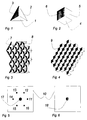
- Fig. 1 shows a pyramidal triple, the each from three adjacent triangular ones Areas (1, 2, 3) of a cube section is formed.
- the triangles are as shown equilateral triangles, they but can also have different leg lengths to have.
- 1 has the pyramidal Triple a vertical alignment of his Central axis. The central axis can also lie outside the solder.
- Fig. 2 shows a full cube triple each from three adjacent square Surfaces (1, 2, 3) of a cube corner are formed becomes.
- 2 has the full cube triple a vertical alignment of its central axis.
- the central axis can also lie outside the solder.
- Fig. 3 shows a section of a Retroflector made of pyramidal triples (7, 8) as shown in Fig. 1 is formed where the area from triples is different Orientation exists.
- Tripel (8) is over Rotated 180 ° to triple (7).
- Fig. 4 shows a section of a Retroflector made of full-cube triples exists, the projected area is a six-sided honeycomb. Of the Retroflector is made of full-cube triples (9), as shown in Fig. 2, same orientation educated. It can also be made from triples different rotational orientation formed be.
- Fig. 5 shows a monitor surface (10) of a Measuring system for retroreflected laser light, one with laser light pyramidal retroflector observed.
- the Monitor On the Monitor are the six retro-reflected Vitreous Irritation Beams (11, 12, 13, 14, 15, 16) and the retroflected Central beam (17) visible.
- Fig. 6 shows a monitor surface (10) of a Measuring system for retroreflected laser light, one with laser light Retroflector from full-cube triples observed.
- Fig. 7 shows a laser beam in the form an Elypse (20) and the center (19), the meets a retro reflector made of full-cube triples consists.
- the full cube triples are only with your base as a honeycomb shown.
- the Elypse touches 7 honeycombs.
- the means with retroflexion in this case are 7 full cube triples at retroflexion of the laser beam involved.
- everyone Fullcube triples offset the outgoing ones Rays to the axis of the incoming Rays. This will make the incoming one Beams of rays during retroflexion in his Shape distorted depending on the number of full cube triples involved and their location to each other.
- 8 to 15 show the same Beams in the shape of an ellipse. At 8 to 15 is the center (19) with its ellipse (20) relative to the respective Honeycomb offset. By changing the position of the ray bundle changing honeycomb touches. This has one each other beam deformation of the retroflected rays.
- FIG. 8 are 5 honeycombs from the beam 9, there are 7 honeycombs in FIG. 10 are 6 honeycombs, in Fig. 11 are 7 honeycombs, in FIG. 12 is 5 honeycombs, in FIG. 13 there are 5 honeycombs, in FIG. 14 there are 6 honeycombs and in FIG. 15 5 honeycombs are touched.
- Fig. 16 shows a special training of Microretroflector. It is a exemplary retroflector made of two full cube triples of different sizes. Of the Retroflector with approx. 100 x 100 mm Edge length has two screw holes (22) for fixing. The vast majority of the Retroflector is made of full-cube triples (23) formed with a wrench size of 4 mm. At the center of the retroflector is an area (24) of smaller full cube triples in the size of about 1 mm Key-width.
- FIG. 17 shows an enlarged detail an area of Fig. 16, in which the Surfaces made of large-format full cube triples (23) to the surface of the small format Fullcube triple (24) hits. Both areas touch without a special dividing line.
- the retroflector for measuring tasks with 16 can be infinitely variable Measuring distance and the associated Enlargement or reduction of the Light cone of the transmitted beam is reached be, with relative constancy of the form of the retroflected rays.
Abstract
Description
Die Erfindung betrifft eine Sensoreinrichtung, die auf der Retroreflexion eines Laserstrahles basiert.The invention relates to a sensor device based on retroreflection of a laser beam.
Ziel dieser Sensoreinrichtung ist es, für die auf Retroreflexion und Polasationsdrehung basierende Lasersensorik eine in der Praxis einfach zu handhabende retroflektive Fläche zu schaffen, die ein konturenscharfes Lasersignal zur Auswertung liefert und damit wesentlich bessere, hochauflösende Feinabtastung ermöglicht.The aim of this sensor device is for retroreflection and polarization rotation based laser sensor technology is easy in practice to create a manageable retroflective surface that is sharply contoured Laser signal for evaluation delivers and thus much better, high-resolution Fine scanning enabled.
In der DE 42 40 680 A1 ist ein Verfahren zur Herstellung von strukturierten Mikrotripel-Reflexflächen beschrieben, gemäß welchem die retroreflektierenden Mikrotripel würtelähnlich sind und einen Durchmesser von 0,002 mm bis 0,8 mm haben und in Gruppen gleicher Mikrotripel zusammengefaßt sind, wobei der Durchmesser der Gruppen kleiner als 7 mm ist und mindestens zwei Gruppen und/oder mehr die Reflexfläche bilden. DE 42 40 680 A1 describes a process for the production of structured microtripel reflex surfaces described, according to which the retroreflective microtriples are cube-like and have a diameter from 0.002 mm to 0.8 mm and combined in groups of the same microtriples where the diameter of the groups is less than 7 mm and at least two groups and / or more is the reflective surface form.
In der JP 6-273608, Patent abstracts of Japan, ist ein Rückstrahler beschrieben, der eine große Reflexionseffizienz aufweist durch Bildung einer Mehrzahl von Würfelecken, die im gemischten Zustand auf der Reflexionsfläche und mit verschiedenen Formaten angeordnet sind.A reflector is described in JP 6-273608, Patent abstracts of Japan, which has a high reflection efficiency by forming a Plurality of cube corners, in the mixed state on the reflection surface and arranged with different formats.
In der Sensorik sind auf Retroreflexion und Polarisationsdrehung basierende Lasersensorsysteme z. B. als Reflexlichtschranken bekannt. Diese mit Laserlicht und Polarisationsfilter arbeitenden Reflexlichtschranken werden mit Retroreflektoren verwendet. Als Retroreflektoren gibt es dazu großformatig geschliffene, teuere Glastripel, Hohlspiegel aus Metall und herkömmliche Tripelrückstrahler aus Glas oder Kunststoff. Die Strahlunterbrechung des retroreflektierten Strahles zwischen Retroreflektor und Sender/Empfänger wird als binäres Signal interpretiert.The sensors are based on retroreflection and polarization rotation Laser sensor systems e.g. B. known as reflex light barriers. This reflex light barriers working with laser light and polarization filter are used with retroreflectors. There are also retroreflectors large format, expensive glass triple, concave mirror made of metal and conventional triple reflectors made of glass or plastic. The beam interruption of the retroreflected beam between the retroreflector and The transmitter / receiver is interpreted as a binary signal.
Bei der Entfernungsmessung mit Reflexsensorsystemen wird die benötigte Zeit bis zur Rückkehr des retroreflektierten Strahles zur Berechnung des Weges ermittelt. Es wird heute Laserlicht bevorzugt, um die Aufspreizung des Lichtstrahles möglichst gering zu halten und so ein konturscharfes und energetisch starkes Signal zur Auswertung zu erhalten.When measuring distance with reflex sensor systems, the required Time until the retroreflected beam returns for calculation determined the way. Today, laser light is preferred to spread it to keep the light beam as low as possible and thus keep the contours sharp and to receive an energetically strong signal for evaluation.
Bei der Gasanalyse wird das im gasdurchströmten Raum veränderte Spektrum des retroreflektierten Strahles ausgewertet.Gas analysis changes that in the gas-flowed room Spectrum of the retroreflected beam evaluated.
Um Fehler bei der Signalauswertung zu vermeiden, wird der Laserstrahl oft zusätzlich polarisiert und/oder gepulst und/oder auf bestimmte Lichtspektren begrenzt.In order to avoid errors in the signal evaluation, the laser beam often additionally polarized and / or pulsed and / or to certain light spectra limited.
Entscheidend ist bei allen genannten Systemen, einen möglichst konturscharfen retroreflektierten Strahl für die Signalauswertung zu erhalten, der von Fremdlicht oder unerwünschten Reflexionsstrahlen unterscheidbar ist. It is crucial for all the systems mentioned that the contours are as sharp as possible to obtain retroreflected beam for signal evaluation, the is distinguishable from extraneous light or unwanted reflection rays.
Solche unerwünschten Reflexionsstrahlen bilden sich z. B. bei der Beobachtung von Glaskörpern in einer Flaschenabfüllanlage. Ebenso entstehen Reflexionen auf Metall-, Lack- oder Kunststoff-Oberflächen, z. B. bei der sensorischen Beobachtung von Paketen in der Paketverteilung, in Förderanlagen, bei der sensorischen Abtastung von Kraftfahrzeugen in Waschanlagen.Such undesirable reflection rays form e.g. B. in observation of glass bodies in a bottle filling system. Likewise arise Reflections on metal, paint or plastic surfaces, e.g. B. in the sensory observation of parcels in the parcel distribution, in Conveyors, in the sensory scanning of motor vehicles in Car washes.
Die Feinauflösung des Reflexsensorsystems ist davon abhängig, daß der Retroreflektor ein konturscharfes, ein nicht mit Fremdstrahlung verwechselbares Signal erhält.The fine resolution of the reflex sensor system depends on the Retroreflector a sharply contoured, one that cannot be confused with external radiation Receives signal.
Um dies zu erreichen, wird Laserlicht bevorzugt. Jedoch zeigt sich, daß herkömmliche Retroreflektoren in ausreichender Präzision zu unwirtschaftlich in der Herstellung sind oder aber den Laserstrahl nachteilig verändern, wenn die Lichtquelle sich bewegt, z. B. durch Erschütterungen, wenn der Sensor an einer Maschine befestigt ist.To achieve this, laser light is preferred. However, it turns out that conventional retroreflectors with sufficient precision are too uneconomical are in the process of manufacture or adversely affect the laser beam, when the light source is moving, e.g. B. by vibrations, if the sensor is attached to a machine.
Durch die Sensoreinrichtung gemäß der Erfindung soll eine wesentliche Verbesserung der Feinabtastung des Sensorsystems durch exakte Umlenkung des Laserstrahles im Retroflektor und Rücksendung eines konturenscharfen Signals bewirkt werden.The sensor device according to the invention is intended to be an essential one Improvement of the fine scanning of the sensor system through exact redirection of the laser beam in the retroflector and return of a sharp contour Signal are caused.
Zur Lösung dieser Aufgabe wird eine Sensoreinrichtung, die auf der Retroreflexion eines Laserstrahls basiert, gemäß Patentanspruch 1 vorgeschlagen. Hierbei sind folgende Regeln zu beachten.To solve this problem, a sensor device based on the retroreflection a laser beam based, proposed according to claim 1. The following rules must be observed.
Der Retroflektor soll aus einer Fläche, vieler aneinandergereihter, kleiner Tripel bestehen. Je kleiner der Tripel, je kleiner ist auch der störende Strahlversatz zwischen eingehendem und ausgehendem Lichtstrahl.The retroflector should consist of one surface, many small triple consist. The smaller the triple, the smaller is also the annoying beam offset between incoming and outgoing light beam.
Zum Bau eines solchen aus vielen Tripeln bestehenden Retroflektors für die Lasersensorik wird als einzig geeigneter Retroflexionskörper vorgeschlagen der würfelförmige Fullcube, oder auch Perkin-Elmer-Pyramide genannt. Seine rechteckigen Reflexionsflächen stehen mit etwa 90° zueinander.To build one from many triples existing retroflector for the Laser sensor technology is considered the only suitable one Retroflexion body suggested the cube-shaped full cube, or Perkin-Elmer pyramid called. Its rectangular Reflection surfaces are at about 90 ° to each other.
Dagegen eignet sich nicht der pyramidale Tripel, der nur ein Würfeleckenabschnitt ist.In contrast, the pyramidal is not suitable Triple, which is just a cube corner section.
Für die folgende Erklärung wird angenommen, daß das eintreffende Licht exakt senkrecht zur Oberfläche des pyramidalen Tripelretroflektors eintrifft.For the following explanation it is assumed that the incoming light is exactly vertical to the surface of the pyramidal triple retroflector arrives.
Die Reflexionsflächen des pyramidalen Tripels sind dreieckig. Auf Ihnen befinden sich Teilflächen, die bei der Strahlumlenkung keine geeigneten Referenzpunkte auf den anderen Teilflächen des Tripels finden, um die eintreffenden Laserstrahlen vollständig zu retroflektieren. Die Strahlen, die keine geeigneten Referenzpunkte für die Lichtumlenkung gefunden haben, um zurückzukehren, werden durch den Glaskörper des aus vielen Tripeln bestehenden Retroflektors gesandt. Diese Strahlen werden hier Glaskörperirrstrahlen genannt.The reflection surfaces of the pyramidal triple are triangular. Are on you Subareas during beam deflection no suitable reference points on the find other partial areas of the triple order the incoming laser beams completely to retroflect. The rays that do not suitable reference points for the light deflection have found to return are made by the vitreous of many Triples existing retroflector sent. These rays become vitreous cirrhosis here called.
Bei ihrem Weg durch den Glaskörper des pyramidalen Tripelretroflektors treffen die Glaskörperirrstrahlen dann auf einen benachbarten Tripel und dringen in ihm ein. Innerhalb des Nachbartripels treffen sie auf eine Reflexionsfläche, die die Strahlen nun zurückkehren läßt. Als Ergebnis erhält man statt eines retroflektierten Strahlenbündels sieben Retroflexionsstrahlenbündel.On its way through the vitreous of the pyramidal triple retroflector hit the Vitreous Irradiation then hits you neighboring triple and penetrate into it. They meet within the neighboring triple a reflection surface that the rays now lets return. As a result you get instead of a retro-reflected beam seven retroflexion beams.
Betrachtet man die Pyramiden von oben, so erkennt man, daß jeweils 2 Pyramiden eine gemeinsame Kathete haben, und daß diese Tripel zueinander um 180° gedreht sind. Ein pyramidaler Retroflektor besteht also aus zwei Gruppen gleichartiger, aber in ihrer Ausrichtungslage verschiedener Tripel.If you look at the pyramids from above, so you can see that 2 pyramids each one have common cathete and that this Triples are rotated by 180 ° to each other. A pyramidal retroflector consists of two groups of the same kind, but in their Alignment of different triples.
Jede Ecke des Fußes einer solchen Tripel-Pyramide hat einen Teilbereich, dem die dritte Referenzfläche für einen vollständigen Strahlengang für die Retroflexion fehlt. Jede Ecke erzeugt also ein Strahlenbündel von Glaskörperirrstrahlen, die durch den optischen Glaskörper irren, bis sie auf wirksame Umlenkflächen trefffen.Every corner of the foot of such a triple pyramid has a section that the third reference surface for a complete Beam path for retroflexion is missing. Each So corner creates a ray of Vitreous Irritation Radiated by the erroneous optical vitreous until they open meet effective deflection surfaces.
So entstehen aus zwei mal drei Ecken, die alle in eine andere Richtung zeigen, sechs getrennte Strahlenbündel, die aus Glaskörperirrstrahlen bestehen und in Nachbartripeln erst die geignete Referenzfläche gefunden haben, um zurückzukehren. Alle sechs Glaskörperirrstrahlenbündel bilden bei ihrer Rückkehr ein Muster, das den Eckpunkten eines Sechsecks entspricht. Denn alle Richtungen der Ecken der Pyramiden, sind jeweils 60° verdreht zueinander.So from two times three corners, the all pointing in a different direction, six separate bundles of rays that consist of vitreous rays exist and in neighboring triplets only the suitable reference surface was found have to return. All six Vitreous cirrus rays form in her Return a pattern that is the cornerstones of a Hexagons. Because all directions the corners of the pyramids are 60 ° each twisted to each other.
Der ausgesendete Laserstrahl, der hier als Sendestrahlbündel bezeichnet werden muß, trifft auf eine oder mehrere pyramidale Tripel, abhängig davon, ob er im Durchmesser nur eine oder mehrere Lichteintrittsflächen der Tripel trifft. Die Lichteintrittsfläche ist ein Dreieck und ist der Fuß der dreiseitigen Pyramide.The emitted laser beam, which here as Transmit beam must be designated meets one or more pyramidal Triple, depending on whether it is in diameter only one or more light entry areas the triple hits. The light entry area is a triangle and is the foot of the three-sided pyramid.
Der Teil des ausgesendeten Laserstrahlbündels, der in das Zentrum der Pyramide oder Pyramiden trifft und dort geeignete Referenzpunkte zur Lichtumlenkung und vollständigen Retroflexion findet, kehrt als Zentralstrahlenbündel zurück. So ergibt sich bei senkrechter Bestrahlung des pyramidalen Retroflektors mit einem Laserstrahlenbündel ein Retroflexionsmuster, das aus einem Zentralstrahlenbündel und sechs umgebenden Glaskörperirrstrahlen besteht.The part of the emitted laser beam, which in the center of the pyramid or Pyramids meets and there suitable reference points for redirecting light and complete Retroflexion takes place, returns as a central ray back. This results in vertical irradiation of the pyramidal Retroflector with a laser beam a retroflexion pattern consisting of a Central beam and six surrounding Vitreous cirrus rays exist.
Der pyramidale Retroflektor antwortet auf ein ausgesendetes Laserstrahlbündel, dem Sendestrahlbündel, mit sieben getrennten Laserstrahlbündeln, nämlich dem retroflektiertem Zentralstrahlbündel und sechs Glaskörperirrstrahlenbündeln. Deshalb ist der pyramidale Retroflektor zur Feinabtastung mit Laserlicht ungeignet.The pyramidal retroflector responds to one emitted laser beam, the Broadcasting beam, with seven separate ones Laser beam bundles, namely the retroflected Central beam and six Vitreous Irrigation Beams. Therefore the pyramidal retroflector for fine scanning unsuitable with laser light.
Dagegen antwortet der Retroflektor aus würfelförmigen Fullcube-Tripeln mit einem einzigen Zentralstahlbündel. Diese Lehre ist besonders wichtig, um zu verstehen, warum Retroflektoren mit Fullcube-Tripeln für das erfindungsgemäße Verfahren vorgeschlagen werden.The retroflector replies against this cube-shaped full cube triples with one single central steel bundle. This teaching is especially important to understand why Retroflectors with full cube triples for that proposed method according to the invention become.
Mit der Kleinheit der Tripel wächst die Positionsgenauigkeit des Meßsystems.With the smallness of the triple it grows Position accuracy of the measuring system.
Das erfindungsgemäße Verfahren zeigt die Verwendung eines Retroflektors, der aus einer Vielzahl von Tripeln besteht. Denn viele kleine Tripel sind einem großen Tripel vorzuziehen. Je kleiner die Tripel, um so kleiner ist der Strahlversatz.The inventive method shows the Use of a retroflector consisting of a Variety of triples. Because many small triples are a large triple preferable. The smaller the triple, the more the beam offset is smaller.
Für ein exaktes Meßsystem ist die Form des retroflektierten Strahlenbündels entscheidend.The shape is for an exact measuring system of the retro-reflected beam crucial.
Was aber bei bisherigen Retroflektoren, die aus einer Vielzahl von Tripeln bestehen, außeracht gelassen wurde, ist, daß das Sendestrahlbündel seine Form verändert, wenn es retroflektiert wird.But what with previous retroflectors that consist of a multitude of triples, has been neglected is that the Transmitting beam changes shape when it is retroflected.
Eine einfache Ursache ist, daß die reflektierenden Teilflächen der Tripel nicht im Winkel exakt stehen oder die Teilflächen nicht planeben sind, sondern rauh oder gewölbt. Aber auch wenn die Teilflächen optisch korrekt gestaltet sind, sind weitere wichtige Regeln zu beachten.A simple reason is that the reflective partial areas of the triple not stand exactly at an angle or the partial areas are not flat, but rough or arched. But even if the subareas are optically correct, there are others important rules to follow.
Die Fullcube-Tripel müssen zueinander absolut gleichmäßig ausgerichtet sein. Sonst wird das retroflektierte Strahlenbündel unnötig aufgeweitet und verformt.The full-cube triples must be absolute to each other be evenly aligned. Otherwise it will retroflected beams unnecessary expanded and deformed.
Die Fullcube-Tripel müssen so klein gewählt werden, daß das Sendestrahlbündel mindestens 5 Fullcube-Tripel des Retroflektors trifft. Wird die Zahl der getroffenen Tripel erhöht, steigt die relative Formstabilität des retroflektierten Strahlenbündels.The full cube triples must be chosen so small be that the transmit beam at least 5 full-cube triple of the retroflector hits. If the number of triples hit is increased, the relative dimensional stability of the retroflected rays.
Die Ursache für die Formveränderung des retroflektierten Strahlenbündels liegt in der Geometrie der Fullcube-Tripel. Jeder Fullcube-Tripel hat von oben senkrecht betrachtet eine waagerechte Schnittfläche in Form eines Sechsecks. Alle Fullcube-Tripel bilden also eine Fläche von sechseckigen Spiegeln, hier Waben genannt, die aneinandergereiht ein bienenwabenförmiges Muster ergeben.The cause of the change in shape of the retroflected beam lies in the Full cube triple geometry. Every full cube triple viewed vertically from above horizontal cutting surface in the form of a Hexagons. All full cube triples form an area of hexagonal mirrors, here Called honeycombs, which are strung together honeycomb pattern.
Bewegt man nun ein Sendestrahlenbündel in Form eines Kreises oder einer Elypse über die bienenwabenförmigen Spiegelflächen, so verändert sich ständig die Zahl der angesprochenen Spiegel. Man kann den Strahl in seinem Durchmesser oder Form zwar verkleinern, so daß er nur eine Wabe trifft und schmäler und kürzer als die Außenkante einer Wabe ist. Dann jedoch würde der Sendestrahl beim Auftreffen auf die Kante der Wabe nicht mehr retroflektiert.Now move a bundle of transmitted rays in Form a circle or an ellipse over the honeycomb-shaped mirror surfaces, see above the number of addressed mirror. You can see the beam in its diameter or shape downsize so that it only hits a honeycomb and narrower and shorter than the outer edge of a honeycomb is. Then, however, the transmission beam would No longer hit the edge of the honeycomb retroflected.
Der Strahl muß also mindestens so groß sein in seiner Form, daß er beim Übergang von einer Wabe zur nächsten Wabe beide Waben zugleich berührt. Da das Licht im Fullcube-Tripel umgelenkt wird, werden immer drei Punkte in einer Wabe berührt, die abhängig vom Einstrahlwinkel voneinander entfernt liegen, verteilt über die Wabe.The beam must therefore be at least as large in the form that it is in the transition from one honeycomb to the next honeycomb both honeycombs at the same time touched. Because the light in the full-cube triple is redirected, always three points in touches a honeycomb that depends on the Angles of incidence are apart, spread over the honeycomb.
Bewegt man also das Sendestrahlbündel über die Waben und ist es kleiner im Durchmesser als der gedachte Innenkreis eines Sechsecks, dann werden je nach Position ein oder zwei oder drei Waben beleuchtet. Das bedeutet, daß das retroflektierte Strahlenbündel in seiner Form sich während der Bewegung verändert von 100% nach bis zu 200% oder nahezu 300%.So if you move the transmitted beam over the Honeycomb and it is smaller in diameter than the imaginary inner circle of a hexagon, then will be one or two or depending on the position three honeycombs illuminated. That means that retroflected rays in his Shape changes during movement 100% after up to 200% or almost 300%.
Solche starken Schwankungen der Form des retroflektierten Strahles müssen verhindert werden, um möglichst präzise zu messen. Mit der Vergrößerung der Form des Sendestrahles oder mit der Verkleinerung der Fullcube-Tripel nimmt die Zahl der berührten Waben zu, jedoch die Schwankungsbreite der berührten Waben während der Bewegung des Sendestrahlbündels nimmt ab und damit verringert sich die relative Verformung des retroflektierten Strahlenbündels erheblich.Such large fluctuations in the shape of the retroflected beam must be prevented to measure as precisely as possible. With the enlargement of the shape of the transmission beam or by reducing the full-cube triple the number of honeycombs touched increases however the range of fluctuation of the touched Honeycomb during the movement of the transmission beam decreases and thus decreases the relative deformation of the retroflected Beam considerably.
Es wird deshalb vorgeschlagen, das Sendestrahlbündel in seiner Form so zu wählen, daß es bei Bewegung über den Retroflektor in jeder Position mindestens 5 oder mehr Fullcube-Tripel zugleich berührt. Für Laserabtastungen des Retroflektors wird für die Praxis eine Schlüsselweite der Fullcube-Tripel von 0,002 mm bis 1,4 mm vorgeschlagen, und die Schlüsselweite, den Abstand zweier paralleler Seiten der sechsseitigen Grundfläche des Fullcube-Tripels beschreibt.It is therefore proposed that Broadcast beam in its shape choose that when moving over the Retroflector in every position at least 5 or more full-cube triples at the same time touched. For laser scans of the In practice, retroflector becomes one Wrench size of the full-cube triple from 0.002 mm to 1.4 mm suggested, and the Width across flats, the distance between two parallel sides of the six-sided Base area of the full cube triple describes.
Fig. 1 zeigt einen pyramidalen Tripel, der jeweils aus drei angrenzenden dreieckigen Flächen (1, 2, 3) eines Würfelabschnittes gebildet wird. Die Dreiecke sind als gleichseitige Dreiecke dargestellt, sie können aber auch verschiedene Schenkellängen haben. In der Fig. 1 hat der pyramidale Tripel eine lotrechte Ausrichtung seiner Mittelachse. Die Mittelachse kann aber auch außerhalb des Lotes liegen.Fig. 1 shows a pyramidal triple, the each from three adjacent triangular ones Areas (1, 2, 3) of a cube section is formed. The triangles are as shown equilateral triangles, they but can also have different leg lengths to have. 1 has the pyramidal Triple a vertical alignment of his Central axis. The central axis can also lie outside the solder.
Fig. 2 zeigt einen Fullcube-Tripel, der jeweils aus drei angrenzenden quadratischen Flächen (1, 2, 3) einer Würfelecke gebildet wird. In der Fig. 2 hat der Fullcube-Tripel eine lotrechte Ausrichtung seiner Mittelachse. Die Mittelachse kann aber auch außerhalb des Lotes liegen. Fig. 2 shows a full cube triple each from three adjacent square Surfaces (1, 2, 3) of a cube corner are formed becomes. 2 has the full cube triple a vertical alignment of its central axis. The central axis can also lie outside the solder.
Fig. 3 zeigt einen Ausschnitt eines Retroflektors der aus pyramidalen Tripeln (7, 8), wie in Fig. 1 gezeigt, gebildet wird, wobei die Fläche aus Tripel unterschiedlicher Drehorientierung besteht. Tripel (8) ist um 180° zu Tripel (7) gedreht.Fig. 3 shows a section of a Retroflector made of pyramidal triples (7, 8) as shown in Fig. 1 is formed where the area from triples is different Orientation exists. Tripel (8) is over Rotated 180 ° to triple (7).
Fig. 4 zeigt einen Ausschnitt eines Retroflektors, der aus Fullcube-Tripeln besteht, deren projezierte Grundfläche jeweils eine sechsseitige Wabe ist. Der Retroflektor ist aus Fullcube-Tripeln (9), wie in Fig. 2 gezeigt, gleicher Ausrichtung gebildet. Er kann aber auch aus Tripeln unterschiedlicher Drehorientierung gebildet sein.Fig. 4 shows a section of a Retroflector made of full-cube triples exists, the projected area is a six-sided honeycomb. Of the Retroflector is made of full-cube triples (9), as shown in Fig. 2, same orientation educated. It can also be made from triples different rotational orientation formed be.
Fig. 5 zeigt eine Monitorfläche (10) eines Meßsystems für retroflektiertes Laserlicht, das einen mit Laserlicht angestrahlten pyramidalen Retroflektor beobachtet. Auf dem Monitor sind die sechs retroflektierten Glaskörperirrstrahlenbündel (11, 12, 13, 14, 15, 16) und das retroflektierte Zentralstrahlbündel (17) sichtbar.Fig. 5 shows a monitor surface (10) of a Measuring system for retroreflected laser light, one with laser light pyramidal retroflector observed. On the Monitor are the six retro-reflected Vitreous Irritation Beams (11, 12, 13, 14, 15, 16) and the retroflected Central beam (17) visible.
Fig. 6 zeigt eine Monitorfläche (10) eines Meßsystems für retroflektiertes Laserlicht, das einen mit Laserlicht angestrahlten Retroflektor aus Fullcube-Tripeln beobachtet. Fig. 6 shows a monitor surface (10) of a Measuring system for retroreflected laser light, one with laser light Retroflector from full-cube triples observed.
Auf dem Monitor sind keine Glaskörperirrstrahlenbündel, sondern nur ein einziges retroflektiertes Zentralstrahlbündel (18) sichtbar.There are no vitreous rays on the monitor, but only one retro-reflected central beam (18) visible.
Fig. 7 zeigt ein Laserstrahlbündel in Form einer Elypse (20) und dem Zentrum (19), das auf einen Retroflektor trifft, der aus Fullcube-Tripeln besteht. Die Fullcube-Tripel sind nur mit Ihrer Grundfläche als Wabe dargestellt. Die Elypse berührt 7 Waben. Das bedeutet, bei Retroflexion in diesem Fall, sind 7 Fullcube-Tripel an der Retroflexion des Laserstrahlenbündels beteiligt. Jeder Fullcube-Tripel versetzt die ausgehenden Strahlen zur Achse der eintreffenden Strahlen. Dadurch wird das eintreffende Strahlenbündel bei der Retroflexion in seiner Form verzerrt, abhängig von der Zahl der beteiligten Fullcube-Tripel und ihrer Lage zueinander.Fig. 7 shows a laser beam in the form an Elypse (20) and the center (19), the meets a retro reflector made of full-cube triples consists. The full cube triples are only with your base as a honeycomb shown. The Elypse touches 7 honeycombs. The means with retroflexion in this case, are 7 full cube triples at retroflexion of the laser beam involved. Everyone Fullcube triples offset the outgoing ones Rays to the axis of the incoming Rays. This will make the incoming one Beams of rays during retroflexion in his Shape distorted depending on the number of full cube triples involved and their location to each other.
Fig. 8 bis 15 zeigen das gleiche Strahlenbündel in Form einer Elypse. Bei jeder Fig. 8 bis 15 ist aber das Zentrum (19) mit seiner Elypse (20) relativ zur jeweiligen Wabe etwas versetzt. Durch die Positionsänderung des Strahlenbündels werden wechselnde Waben berührt. Dies hat eine jeweils andere Strahlverformung des retroflektierten Strahlenbündels zur Folge.8 to 15 show the same Beams in the shape of an ellipse. At 8 to 15 is the center (19) with its ellipse (20) relative to the respective Honeycomb offset. By changing the position of the ray bundle changing honeycomb touches. This has one each other beam deformation of the retroflected rays.
In Fig. 8 sind 5 Waben vom Strahlenbündel
berührt, in Fig. 9 sind 7 Waben, in Fig. 10
sind 6 Waben, in Fig. 11 sind 7 Waben, in
Fig. 12 sind 5 Waben, in Fig. 13 sind 5
waben, in Fig. 14 sind 6 Waben und in Fig. 15
sind 5 Waben berührt.In Fig. 8 are 5 honeycombs from the
Somit ist in diesem Beispiel die niedrigste
Wabenzahl 5 und höchste Wabenzahl 7. Die
dargestellte Elypse entspricht also einem
Laserstrahlbündel in der vorgeschlagenen,
relativen Mindestgröße von 5 Fullcube-Tripeln.This is the lowest in this
Fig. 16 zeigt eine Sonderausbildung des Mikroretroflektors. Es ist ein beispielhafter Retroflektor aus zwei verschieden großen Fullcube-Tripeln. Der Retroflektor mit ca. 100 x 100 mm Kantenlänge besitzt zwei Schraublöcher (22) zur Befestigung. Der überwiegende Teil des Retroflektors ist aus Fullcube-Tripeln (23) mit einer Schlüsselweite von 4 mm gebildet. Im Zentrum des Retroflektors befindet sich eine Fläche (24) von kleineren Fullcube-Tripeln in der Größe von etwa 1 mm Schlüsselweite. Fig. 16 shows a special training of Microretroflector. It is a exemplary retroflector made of two full cube triples of different sizes. Of the Retroflector with approx. 100 x 100 mm Edge length has two screw holes (22) for fixing. The vast majority of the Retroflector is made of full-cube triples (23) formed with a wrench size of 4 mm. At the center of the retroflector is an area (24) of smaller full cube triples in the size of about 1 mm Key-width.
Auch bei dieser Sonderausbildung werden die genannten Regeln gewahrt.With this special training, too rules mentioned.
Fig. 17 zeigt eine Ausschnittvergrößerung eines Bereiches der Fig. 16, in der die Flächen aus großformatigen Fullcube-Tripeln (23) an die Fläche der kleinformatigen Fullcube-Tripel (24) trifft. Beide Flächen berühren sich ohne besondere Trennlinie.17 shows an enlarged detail an area of Fig. 16, in which the Surfaces made of large-format full cube triples (23) to the surface of the small format Fullcube triple (24) hits. Both areas touch without a special dividing line.
Diese Bauweise ist dann vorteilhaft, wenn der Retroflektor aus sehr unterschiedlichen Entfernungen beobachtet werden soll. Mit zunehmender Entfernung nimmt der Durchmesser des Sendestrahlbündels naturgemäß zu und berührt eine immer größere Fläche des Retroflektors. Hat das auf die Mitte des Retroflektors gerichtete Sendestrahlbündel einen Durchmesser in diesem Beispiel von etwa 30 mm überschritten, dann berührt es nicht nur die kleinformatigen Fullcube-Tripel, sondern auch die großformatigen Fullcube-Tripel. Letztere haben im allgemeinen eine etwas höhere Retroflexionsleistung, weil die Gesamtfläche der Retroflexion weniger Tripelkanten enthält. Denn jede Kante ist eine streuende, nicht retroflektierende Fläche. Durch Verwendung von größeren Fullcube-Tripeln bei größerem Abtastäbstand zwischen Sender und Retroflektor wird der Energieverlust durch höhere Retroflexionsleistung der großen Tripel ausgeglichen.This design is advantageous if the Retro reflector made of very different Distances should be observed. With the distance increases with increasing diameter the transmission beam naturally to and touches an ever larger area of the Retroflector. Did that on the middle of the Retroflector directed transmission beam a diameter of about 30 mm in this example exceeded, then it does not only affect the small-format full-cube triple, but also the large-format full-cube triples. Latter generally have a slightly higher one Retroflexion performance because of the total area the retroflexion of fewer triple edges contains. Because every edge is a scattering, non-retro-reflective surface. By Use of larger full cube triples larger scanning distance between transmitter and Retroflector is the energy loss through higher retroflexing performance of the large ones Triple balanced.
In Abhängigkeit von der Größe des Sendestrahlbündel-Durchmessers oder seiner Form, sollten die Schlüsselweiten der Fullcube-Tripel gewählt werden. Je mehr Fullcube-Tripel vom Sendestrahlbündel erfaßt werden, um so geringer wird die prozentuale Verformung des retroflektierten Strahlenbündels ausfallen. Je geringer die Verformung, um so genauer kann mit dem Strahlenbündel gemessen werden.Depending on the size of the transmit beam diameter or its shape, should the key widths of the full cube triple to get voted. The more full cube triples from Broadcast beams are detected, so the percentage deformation of the retroflected rays fail. The less the deformation, the more precise can be measured with the beam.
Mit dem Retroflektor für Meßaufgaben mit Laserlicht in der Fig. 16 kann stufenlos der Meßabstand und die damit verbundene Vergrößerung oder Verkleinerung des Lichtkegels des Sendestrahlbündels erreicht werden, bei relativer Konstanz der Form des retroflektierten Strahlenbündels.With the retroflector for measuring tasks with 16 can be infinitely variable Measuring distance and the associated Enlargement or reduction of the Light cone of the transmitted beam is reached be, with relative constancy of the form of the retroflected rays.
Claims (2)
Priority Applications (1)
| Application Number | Priority Date | Filing Date | Title |
|---|---|---|---|
| DE59803249.5T DE59803249C5 (en) | 1997-06-30 | 1998-05-14 | On the retroreflection of a laser beam based sensor device |
Applications Claiming Priority (2)
| Application Number | Priority Date | Filing Date | Title |
|---|---|---|---|
| DE19727527.3A DE19727527C5 (en) | 1997-06-30 | 1997-06-30 | On the retroreflection of a laser emitter based sensor device |
| DE19727527 | 1997-06-30 |
Publications (2)
| Publication Number | Publication Date |
|---|---|
| EP0889334A1 true EP0889334A1 (en) | 1999-01-07 |
| EP0889334B1 EP0889334B1 (en) | 2002-03-06 |
Family
ID=7833931
Family Applications (1)
| Application Number | Title | Priority Date | Filing Date |
|---|---|---|---|
| EP98108776A Expired - Lifetime EP0889334B1 (en) | 1997-06-30 | 1998-05-14 | Sensor device based on retroreflection of a laser beam |
Country Status (8)
| Country | Link |
|---|---|
| US (1) | US6010223A (en) |
| EP (1) | EP0889334B1 (en) |
| JP (1) | JPH1183727A (en) |
| AT (1) | ATE214165T1 (en) |
| DE (2) | DE19727527C5 (en) |
| DK (1) | DK0889334T3 (en) |
| ES (1) | ES2173526T3 (en) |
| PT (1) | PT889334E (en) |
Families Citing this family (19)
| Publication number | Priority date | Publication date | Assignee | Title |
|---|---|---|---|---|
| DE10119671A1 (en) * | 2001-04-20 | 2002-10-24 | Sen Hans-Erich Gubela | Deflecting mirror structure consisting of a large number of triples |
| US6655215B2 (en) | 2001-06-15 | 2003-12-02 | Honeywell International Inc. | Inverse corner cube for non-intrusive three axis vibration measurement |
| KR100490816B1 (en) * | 2001-06-15 | 2005-05-24 | 샤프 가부시키가이샤 | Micro corner cube array, method of making the micro corner cube array and reflective type display device |
| JP3818906B2 (en) * | 2001-12-13 | 2006-09-06 | シャープ株式会社 | Micro corner cube array, manufacturing method thereof, and display device |
| DE10216579A1 (en) | 2002-04-14 | 2003-10-23 | Sen Hans-Erich Gubela | Wide-angle sensor system with triple reflector and production of the tools |
| DE10228013B4 (en) * | 2002-06-22 | 2005-11-03 | Hans-Erich Sen. Gubela | Partial transmission reflector, use of the partial transmission reflector and optical sensor system |
| US20040080447A1 (en) * | 2002-10-17 | 2004-04-29 | Bas Christophe F. | Miniature omni-directional corner reflector |
| FR2853734B1 (en) * | 2003-04-14 | 2005-05-27 | Tecoptique | SYSTEM FOR VISUALIZING OPTICAL MARKINGS OF OPHTHALMIC GLASS, BUFFERING DEVICE AND GLASS ORIENTATION METHOD USING SUCH A SYSTEM |
| US7030365B2 (en) * | 2004-04-15 | 2006-04-18 | Eaton Corporation | Emitter-detector assembly for a reflex photoelectric object detection system |
| JP2006243618A (en) * | 2005-03-07 | 2006-09-14 | Three M Innovative Properties Co | Cube cornered double-sided retroreflective element |
| DE102007006405B4 (en) | 2007-02-05 | 2012-02-16 | Imos Gubela Gmbh | Reflector with a trapezoidal reflection and method for fine light scanning to detect an object |
| DE102009007124B4 (en) * | 2009-02-02 | 2019-01-10 | Hans-Erich Gubela sen. | Retroreflector with a color filter for optical sensors and reflection light barriers |
| US20150048572A1 (en) * | 2013-03-29 | 2015-02-19 | American Pacific Plastic Fabricators, Inc. | Buoyant target with laser reflectivity |
| USD810323S1 (en) * | 2014-02-04 | 2018-02-13 | Federico Gigli | Tile |
| JP7060198B2 (en) | 2017-02-20 | 2022-04-26 | スリーエム イノベイティブ プロパティズ カンパニー | Retroreflective article containing retarder |
| EP3582642A4 (en) | 2017-02-20 | 2021-01-13 | 3M Innovative Properties Company | Optical articles and systems interacting with the same |
| WO2018152473A1 (en) | 2017-02-20 | 2018-08-23 | 3M Innovative Properties Company | Retroreflecting article with contrast reduction layer |
| WO2019064108A1 (en) | 2017-09-27 | 2019-04-04 | 3M Innovative Properties Company | Personal protective equipment management system using optical patterns for equipment and safety monitoring |
| DE102018112045B4 (en) * | 2018-05-18 | 2021-04-22 | Imos Gubela Gmbh | Retroreflector element and sensor arrangement |
Citations (4)
| Publication number | Priority date | Publication date | Assignee | Title |
|---|---|---|---|---|
| DE2159950B2 (en) * | 1971-12-03 | 1976-08-05 | Fa. Hans Gubela, 5000 Köln | LARGE-AREA TRIPLE REAR REFLECTOR MADE OF PLASTIC |
| US4202600A (en) * | 1978-04-24 | 1980-05-13 | Avery International Corporation | Diced retroreflective sheeting |
| DE4240680A1 (en) * | 1992-12-03 | 1994-06-09 | Gubela Sen Hans Erich | Versatile prodn. of microtriple reflector faces - combining small dice-like units within specific sizes into groups within specific size max to produce desired reflection properties |
| DE29701903U1 (en) * | 1997-02-04 | 1997-03-27 | Imos Gubela Gmbh | Metrology retro reflector |
Family Cites Families (4)
| Publication number | Priority date | Publication date | Assignee | Title |
|---|---|---|---|---|
| US3922065A (en) * | 1968-05-31 | 1975-11-25 | Minnesota Mining & Mfg | Cube-corner retro-reflective article |
| US3712706A (en) * | 1971-01-04 | 1973-01-23 | American Cyanamid Co | Retroreflective surface |
| US4243618A (en) * | 1978-10-23 | 1981-01-06 | Avery International Corporation | Method for forming retroreflective sheeting |
| US5706132A (en) * | 1996-01-19 | 1998-01-06 | Minnesota Mining And Manufacturing Company | Dual orientation retroreflective sheeting |
-
1997
- 1997-06-30 DE DE19727527.3A patent/DE19727527C5/en not_active Expired - Fee Related
-
1998
- 1998-05-14 ES ES98108776T patent/ES2173526T3/en not_active Expired - Lifetime
- 1998-05-14 EP EP98108776A patent/EP0889334B1/en not_active Expired - Lifetime
- 1998-05-14 DE DE59803249.5T patent/DE59803249C5/en not_active Expired - Lifetime
- 1998-05-14 PT PT98108776T patent/PT889334E/en unknown
- 1998-05-14 DK DK98108776T patent/DK0889334T3/en active
- 1998-05-14 AT AT98108776T patent/ATE214165T1/en not_active IP Right Cessation
- 1998-06-22 JP JP10175009A patent/JPH1183727A/en active Pending
- 1998-06-26 US US09/105,143 patent/US6010223A/en not_active Expired - Lifetime
Patent Citations (4)
| Publication number | Priority date | Publication date | Assignee | Title |
|---|---|---|---|---|
| DE2159950B2 (en) * | 1971-12-03 | 1976-08-05 | Fa. Hans Gubela, 5000 Köln | LARGE-AREA TRIPLE REAR REFLECTOR MADE OF PLASTIC |
| US4202600A (en) * | 1978-04-24 | 1980-05-13 | Avery International Corporation | Diced retroreflective sheeting |
| DE4240680A1 (en) * | 1992-12-03 | 1994-06-09 | Gubela Sen Hans Erich | Versatile prodn. of microtriple reflector faces - combining small dice-like units within specific sizes into groups within specific size max to produce desired reflection properties |
| DE29701903U1 (en) * | 1997-02-04 | 1997-03-27 | Imos Gubela Gmbh | Metrology retro reflector |
Also Published As
| Publication number | Publication date |
|---|---|
| DE19727527C2 (en) | 1999-10-14 |
| DK0889334T3 (en) | 2002-06-24 |
| ATE214165T1 (en) | 2002-03-15 |
| DE59803249C5 (en) | 2014-12-31 |
| DE19727527A1 (en) | 1999-02-04 |
| DE59803249D1 (en) | 2002-04-11 |
| JPH1183727A (en) | 1999-03-26 |
| US6010223A (en) | 2000-01-04 |
| EP0889334B1 (en) | 2002-03-06 |
| ES2173526T3 (en) | 2002-10-16 |
| PT889334E (en) | 2002-07-31 |
| DE19727527C5 (en) | 2015-02-19 |
Similar Documents
| Publication | Publication Date | Title |
|---|---|---|
| EP0889334B1 (en) | Sensor device based on retroreflection of a laser beam | |
| DE69836459T2 (en) | Optical element and optical system provided therewith | |
| EP1839083B1 (en) | Device for homogenizing light | |
| DE2653110B2 (en) | Infrared Radiation Intrusion Detector | |
| EP1006382A1 (en) | Apparatus and device for optically converting a light beam | |
| DE69932853T2 (en) | FIGURING ARTICLES AND TWO-AXIS RETRORE-FLYING ELEMENTS USING METHOD | |
| DE102016102591A1 (en) | Device for shaping laser radiation | |
| EP2504710B1 (en) | Optical microarray-based spatial filter, and apparatus and method for measung the velocities of moving objects | |
| EP0025188B1 (en) | Optical arrangement for a photodetector | |
| EP0476361A2 (en) | Reflection light barrier | |
| EP1606579B1 (en) | Lateral surface sensor and imaging lens system therefor | |
| DE10324402A1 (en) | Optical apparatus for imaging, has two superposed arrays, each with set of one- dimensional elongated cylindrical optical units consecutively in parallel and spreading along extension-profiling direction | |
| EP3598186A1 (en) | Retroreflector | |
| EP1709360B1 (en) | System for illuminating large areas in an even or defined manner | |
| EP2056067A2 (en) | Arrangement to depict a line-shaped marking | |
| EP1062538B1 (en) | Device for deviating electromagnetic rays or radiation beams in the optical spectral domain | |
| EP1477774A1 (en) | Position measuring device | |
| EP3572850B1 (en) | Retroreflector element | |
| DE3022365A1 (en) | Optical scanner using rotating mirror - has narrow cylindrical surface on rotor and equally-spaced flat facets | |
| EP3514581B1 (en) | Retroreflector with a curved surface | |
| EP0283717B1 (en) | Opto-mechanical device | |
| EP1176450A2 (en) | Optical beam transforming device | |
| DE3013141C2 (en) | Method and device for the optical display of colored light information | |
| DE3422223A1 (en) | Device, in particular for displacement measurement | |
| DE3521599C1 (en) | Device for generating focused light for conventional light sources |
Legal Events
| Date | Code | Title | Description |
|---|---|---|---|
| PUAI | Public reference made under article 153(3) epc to a published international application that has entered the european phase |
Free format text: ORIGINAL CODE: 0009012 |
|
| AK | Designated contracting states |
Kind code of ref document: A1 Designated state(s): AT BE CH DE DK ES FR GB IT LI PT |
|
| AX | Request for extension of the european patent |
Free format text: AL;LT;LV;MK;RO;SI |
|
| 17P | Request for examination filed |
Effective date: 19990224 |
|
| AKX | Designation fees paid |
Free format text: AT BE CH DE DK ES FR GB IT LI PT |
|
| 17Q | First examination report despatched |
Effective date: 20000616 |
|
| GRAG | Despatch of communication of intention to grant |
Free format text: ORIGINAL CODE: EPIDOS AGRA |
|
| GRAG | Despatch of communication of intention to grant |
Free format text: ORIGINAL CODE: EPIDOS AGRA |
|
| GRAH | Despatch of communication of intention to grant a patent |
Free format text: ORIGINAL CODE: EPIDOS IGRA |
|
| GRAH | Despatch of communication of intention to grant a patent |
Free format text: ORIGINAL CODE: EPIDOS IGRA |
|
| REG | Reference to a national code |
Ref country code: GB Ref legal event code: IF02 |
|
| GRAA | (expected) grant |
Free format text: ORIGINAL CODE: 0009210 |
|
| AK | Designated contracting states |
Kind code of ref document: B1 Designated state(s): AT BE CH DE DK ES FR GB IT LI PT |
|
| REF | Corresponds to: |
Ref document number: 214165 Country of ref document: AT Date of ref document: 20020315 Kind code of ref document: T |
|
| REG | Reference to a national code |
Ref country code: CH Ref legal event code: EP |
|
| PGFP | Annual fee paid to national office [announced via postgrant information from national office to epo] |
Ref country code: BE Payment date: 20020405 Year of fee payment: 5 |
|
| PGFP | Annual fee paid to national office [announced via postgrant information from national office to epo] |
Ref country code: GB Payment date: 20020411 Year of fee payment: 5 |
|
| REF | Corresponds to: |
Ref document number: 59803249 Country of ref document: DE Date of ref document: 20020411 |
|
| REG | Reference to a national code |
Ref country code: CH Ref legal event code: NV Representative=s name: BOVARD AG PATENTANWAELTE |
|
| PGFP | Annual fee paid to national office [announced via postgrant information from national office to epo] |
Ref country code: PT Payment date: 20020513 Year of fee payment: 5 |
|
| PGFP | Annual fee paid to national office [announced via postgrant information from national office to epo] |
Ref country code: CH Payment date: 20020514 Year of fee payment: 5 |
|
| PGFP | Annual fee paid to national office [announced via postgrant information from national office to epo] |
Ref country code: AT Payment date: 20020529 Year of fee payment: 5 |
|
| PGFP | Annual fee paid to national office [announced via postgrant information from national office to epo] |
Ref country code: ES Payment date: 20020610 Year of fee payment: 5 |
|
| REG | Reference to a national code |
Ref country code: DK Ref legal event code: T3 |
|
| ET | Fr: translation filed | ||
| GBT | Gb: translation of ep patent filed (gb section 77(6)(a)/1977) |
Effective date: 20020620 |
|
| REG | Reference to a national code |
Ref country code: PT Ref legal event code: SC4A Free format text: AVAILABILITY OF NATIONAL TRANSLATION Effective date: 20020510 |
|
| REG | Reference to a national code |
Ref country code: ES Ref legal event code: FG2A Ref document number: 2173526 Country of ref document: ES Kind code of ref document: T3 |
|
| PLBE | No opposition filed within time limit |
Free format text: ORIGINAL CODE: 0009261 |
|
| STAA | Information on the status of an ep patent application or granted ep patent |
Free format text: STATUS: NO OPPOSITION FILED WITHIN TIME LIMIT |
|
| 26N | No opposition filed |
Effective date: 20021209 |
|
| PG25 | Lapsed in a contracting state [announced via postgrant information from national office to epo] |
Ref country code: GB Free format text: LAPSE BECAUSE OF NON-PAYMENT OF DUE FEES Effective date: 20030514 Ref country code: AT Free format text: LAPSE BECAUSE OF NON-PAYMENT OF DUE FEES Effective date: 20030514 |
|
| PG25 | Lapsed in a contracting state [announced via postgrant information from national office to epo] |
Ref country code: ES Free format text: LAPSE BECAUSE OF NON-PAYMENT OF DUE FEES Effective date: 20030516 |
|
| PG25 | Lapsed in a contracting state [announced via postgrant information from national office to epo] |
Ref country code: LI Free format text: LAPSE BECAUSE OF NON-PAYMENT OF DUE FEES Effective date: 20030531 Ref country code: CH Free format text: LAPSE BECAUSE OF NON-PAYMENT OF DUE FEES Effective date: 20030531 Ref country code: BE Free format text: LAPSE BECAUSE OF NON-PAYMENT OF DUE FEES Effective date: 20030531 |
|
| BERE | Be: lapsed |
Owner name: *GUBELA HANS-ERICH SEN. Effective date: 20030531 |
|
| PG25 | Lapsed in a contracting state [announced via postgrant information from national office to epo] |
Ref country code: PT Free format text: LAPSE BECAUSE OF NON-PAYMENT OF DUE FEES Effective date: 20031130 |
|
| GBPC | Gb: european patent ceased through non-payment of renewal fee |
Effective date: 20030514 |
|
| REG | Reference to a national code |
Ref country code: CH Ref legal event code: PL |
|
| REG | Reference to a national code |
Ref country code: PT Ref legal event code: MM4A Free format text: LAPSE DUE TO NON-PAYMENT OF FEES Effective date: 20031130 |
|
| REG | Reference to a national code |
Ref country code: ES Ref legal event code: FD2A Effective date: 20030516 |
|
| PGFP | Annual fee paid to national office [announced via postgrant information from national office to epo] |
Ref country code: DE Payment date: 20130525 Year of fee payment: 16 Ref country code: DK Payment date: 20130521 Year of fee payment: 16 |
|
| PGFP | Annual fee paid to national office [announced via postgrant information from national office to epo] |
Ref country code: IT Payment date: 20130527 Year of fee payment: 16 Ref country code: FR Payment date: 20130603 Year of fee payment: 16 |
|
| REG | Reference to a national code |
Ref country code: DE Ref legal event code: R043 Ref document number: 59803249 Country of ref document: DE |
|
| REG | Reference to a national code |
Ref country code: DE Ref legal event code: R119 Ref document number: 59803249 Country of ref document: DE |
|
| REG | Reference to a national code |
Ref country code: DE Ref legal event code: R206 Ref document number: 59803249 Country of ref document: DE Effective date: 20141231 Ref country code: DE Ref legal event code: R043 Ref document number: 59803249 Country of ref document: DE Effective date: 20131031 |
|
| REG | Reference to a national code |
Ref country code: DK Ref legal event code: EBP Effective date: 20140531 |
|
| REG | Reference to a national code |
Ref country code: DE Ref legal event code: R119 Ref document number: 59803249 Country of ref document: DE Effective date: 20141202 |
|
| REG | Reference to a national code |
Ref country code: FR Ref legal event code: ST Effective date: 20150130 |
|
| PG25 | Lapsed in a contracting state [announced via postgrant information from national office to epo] |
Ref country code: IT Free format text: LAPSE BECAUSE OF NON-PAYMENT OF DUE FEES Effective date: 20140514 Ref country code: DK Free format text: LAPSE BECAUSE OF NON-PAYMENT OF DUE FEES Effective date: 20140531 Ref country code: DE Free format text: LAPSE BECAUSE OF NON-PAYMENT OF DUE FEES Effective date: 20141202 |
|
| PG25 | Lapsed in a contracting state [announced via postgrant information from national office to epo] |
Ref country code: FR Free format text: LAPSE BECAUSE OF NON-PAYMENT OF DUE FEES Effective date: 20140602 |