EP0889302B1 - Bicycle display device - Google Patents
Bicycle display device Download PDFInfo
- Publication number
- EP0889302B1 EP0889302B1 EP98112083A EP98112083A EP0889302B1 EP 0889302 B1 EP0889302 B1 EP 0889302B1 EP 98112083 A EP98112083 A EP 98112083A EP 98112083 A EP98112083 A EP 98112083A EP 0889302 B1 EP0889302 B1 EP 0889302B1
- Authority
- EP
- European Patent Office
- Prior art keywords
- display
- bicycle
- switch
- display device
- mode
- Prior art date
- Legal status (The legal status is an assumption and is not a legal conclusion. Google has not performed a legal analysis and makes no representation as to the accuracy of the status listed.)
- Expired - Lifetime
Links
Images


Classifications
-
- B—PERFORMING OPERATIONS; TRANSPORTING
- B62—LAND VEHICLES FOR TRAVELLING OTHERWISE THAN ON RAILS
- B62M—RIDER PROPULSION OF WHEELED VEHICLES OR SLEDGES; POWERED PROPULSION OF SLEDGES OR SINGLE-TRACK CYCLES; TRANSMISSIONS SPECIALLY ADAPTED FOR SUCH VEHICLES
- B62M25/00—Actuators for gearing speed-change mechanisms specially adapted for cycles
- B62M25/08—Actuators for gearing speed-change mechanisms specially adapted for cycles with electrical or fluid transmitting systems
-
- B—PERFORMING OPERATIONS; TRANSPORTING
- B62—LAND VEHICLES FOR TRAVELLING OTHERWISE THAN ON RAILS
- B62J—CYCLE SADDLES OR SEATS; AUXILIARY DEVICES OR ACCESSORIES SPECIALLY ADAPTED TO CYCLES AND NOT OTHERWISE PROVIDED FOR, e.g. ARTICLE CARRIERS OR CYCLE PROTECTORS
- B62J50/00—Arrangements specially adapted for use on cycles not provided for in main groups B62J1/00 - B62J45/00
- B62J50/20—Information-providing devices
- B62J50/21—Information-providing devices intended to provide information to rider or passenger
- B62J50/22—Information-providing devices intended to provide information to rider or passenger electronic, e.g. displays
-
- G—PHYSICS
- G01—MEASURING; TESTING
- G01C—MEASURING DISTANCES, LEVELS OR BEARINGS; SURVEYING; NAVIGATION; GYROSCOPIC INSTRUMENTS; PHOTOGRAMMETRY OR VIDEOGRAMMETRY
- G01C22/00—Measuring distance traversed on the ground by vehicles, persons, animals or other moving solid bodies, e.g. using odometers, using pedometers
- G01C22/002—Measuring distance traversed on the ground by vehicles, persons, animals or other moving solid bodies, e.g. using odometers, using pedometers for cycles
Definitions
- the present invention relates to a bicycle display device for displaying various types of data, such as bicycle speed and distance traveled, which allows the operation of the display elements, sensors, switches, and the like to be self-diagnosed.
- Display devices for displaying various types of data for bicycles are frequently attached to bicycles.
- Display devices capable of displaying such a variety of parameters are equipped with switches for switching the type of parameter on display and indicating the start and stop of measurement.
- the display device is also often detachably attached to the bicycle, with the switches often being integrally provided with the display device. It is known that better operability results when these switches are disposed on lever brackets (brackets for fixing brake levers to the handle bar) (US Patent 4,071,892).
- An object of the present invention is to provide a bicycle display means which allows operations to be checked with a single display device frame, and which allows the source of malfunctions to be readily identified when such malfunctions occur.
- the bicycle display device of the present invention comprises display means having a plurality of display elements; input terminals for inputting sensor signals from sensors for sensing the states of various components of the bicycle; display control means for processing the sensor signals from said input terminals and displaying the desired data on said display means; at least one operating mode switch for switching the operating mode of said display control means; and at least one display mode switch for switching the type of data displayed by said display control means on the display means; wherein the operating modes of said display control means include -- in addition to normal mode, where the bicycle speed, the gear of the shifter, and the like are displayed -- a display diagnostic mode, in which a display making it possible to check whether or not said display elements are operating properly is displayed on said display means, and an input diagnostic mode, in which a display making it possible to check whether or not the sensor signals from the sensors and the switches are operating properly is displayed on said display means.
- the sensors of the aforementioned bicycle display device preferably include a rotation sensor for detecting the wheel rotation.
- the aforementioned sensors of the aforementioned bicycle display device preferably include position sensors for sensing what gear the shifter is in.
- the aforementioned bicycle display device preferably further comprises a start/stop switch for indicating the start and stop of measurement on the aforementioned display control means.
- the aforementioned operating mode switch preferably includes a first operating mode switch and a second operating mode switch; and the aforementioned display control means is such that, in the aforementioned ordinary mode, the aforementioned first operating mode switch is continuously pressed for a first prescribed period of time and is thus switched to the aforementioned display diagnostic mode, while, in the aforementioned display diagnostic mode, the aforementioned second operating mode switch is continuously pressed for a second prescribed period of time and is thus switched to the aforementioned input diagnostic mode.
- the bicycle display device of the present invention comprises: a display device frame; display means mounted on the aforementioned display device frame and having a plurality of display elements; input terminals for inputting sensor signals from sensors for sensing the states of various components of the bicycle; display control means for processing the sensor signals from the aforementioned input terminals and displaying the desired data on the aforementioned display means; at least one operating mode switch for switching the operating mode of the aforementioned display control means; and at least one display mode switch for switching the type of data displayed by the aforementioned display control means on the display means; wherein, among the switches controlling the operation of the aforementioned display control means, the switch that operates while the bicycle is operated is located apart from the aforementioned display device frame; and the operating modes of the aforementioned display control means include -- in addition to normal mode, where the bicycle speed, the gear of the shifter, and the like are displayed -- a display diagnostic mode, in which a display making it possible to check whether or not the aforementioned display elements are operating properly is displayed on the aforementioned display means, and an input
- the bicycle display device preferably further comprises a start/stop switch for indicating the start and stop of measurement on the aforementioned display control means, the aforementioned display mode switch and said start/stop switch being located apart from said display device frame.
- the aforementioned display mode switch and the aforementioned start/stop switch are attached to a lever bracket for fixing an operating lever to the bicycle handle bar.
- Figure 1 depicts the front face of the bicycle display device of the present invention.
- the display device frame 1 is constructed of a nearly square plate-shaped body with rounded corners.
- a liquid crystal panel 51 is attached as the display means to the front face of the display device frame 1.
- Several display elements are incorporated in the liquid crystal display panel 51, allowing various types of data such as speed, distance traveled, the shifter gear, and time, to be displayed, as described below. Display panels based on light-emitting diodes and the like can also be used instead of liquid crystal display panels as the display means.
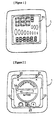
- Figure 2 depicts the back face of the bicycle display device.
- An attaching component 13 is formed on the back face of the display device frame 1, and can be readily attached and detached with a clip (not shown in figure) fixed to the bicycle handle bar.
- a battery lid 14 can be removed with a coin or the like when the battery serving as the power source for the display device is replaced.
- An A switch 21 and B switch 22 for switching the operating mode of the display device are provided on the back face of the display device frame 1.
- An AC switch 23 for initializing data stored in the display device to factory settings and for resetting the display device is similarly provided on the back face.
- Figure 3 depicts the display contents of the liquid crystal display panel 51 of the display device.
- the bicycle speed, time, and other such data are displayed numerically in the main numerical display 52 and auxiliary numerical display 53.
- the content display 54 is a display showing the display contents of the main numerical display 52 and the auxiliary numerical display 53.
- "VEL" indicates traveling speed
- "DST” displays the distance traveled or the cumulative distance
- "CLK” displays the time
- "TIM” displays the traveling time
- "GEA” displays what gear the shifter is in.
- the speed units can be switched between kilometer per hour and miles per hour, and the units of distance can be switched between kilometers and miles.
- the unit display of the liquid crystal display panel 51 also displays the set units.
- the rear sprocket speed step display 55 displays the sprocket speed step of the rear derailleur.
- the rear sprocket speed step display 55 consists of a display of disc shapes lined up from left to right in descending order. This arrangement corresponds to the effective radius of the gears of the actual derailleur.
- the speed steps of the front and rear derailleurs can be set so as to match the actual speed steps of the bicycle. For example, when the rear sprocket is in fifth gear, the rear sprocket speed step display 55 shows the five disc-shaped displays from the left and not the four on the right.
- the front sprocket speed step display 56 displays the sprocket speed step of the front derailleur.
- the front sprocket speed step display 56 consists of a display of disc shapes lined up from left to right in descending order.
- the front sprocket speed step display 56 shows the two disc-shaped displays from the left and not the one on the right.
- the rear and front sprocket speed step displays 55 and 56, respectively, are thus arranged so that the disc-shaped displays corresponding to the gear array of the actual derailleur of the bicycle are in descending order. The speed step can thus be seen intuitively at a glance.
- the positional relation between the group of figures in the front sprocket speed step display 56 and the group of figures in the rear sprocket speed step display 55 is such that the front sprocket speed step display 56 is set up in front or above, intuitively corresponding to the lay out of the actual deraille.
- the disc-shaped displays corresponding to the current gear of the front and rear sprocket speed step displays 56 and 55 begin to blink, and the new gear is displayed.
- the gear can thus be known at a glance.
- the overall status of the sprocket speed step can also be promptly grasped.
- the start/stop switch 24 and the display mode switch 25 are located apart from the display device frame 1 of the display device.
- the start/stop switch 24 is a switch for indicating the start and stop of measurement on the display device when the distance traveled, the lap time, or the like is displayed on the display device.
- the display mode switch 25 is a switch for switching the type of data displayed on the display device. These switches must be operated frequently by the operator while riding the bicycle and are therefore located near the usual grip position for right-handed riders. A lever bracket is a suitable location for these switches.
- Figure 4 depicts a lever bracket on the right side where the start-stop switch 24 and display mode switch 25 are located.
- the lever bracket is a bracket to which is attached an operating lever 3 allowing the brakes to be operated and the shifter to be operated. It is fixed to the bicycle handle bar 15 by a fixing band 16.
- the right side operating lever 3 allows the front brakes to be operated and the rear derailleur to be shifted.
- the entire outer surface of the lever bracket is covered with a synthetic resin bracket cover 17.
- Two push buttons 18 protrude from the bracket cover 17.
- the start/stop switch 24 and the display mode switch 25 of the display device are located inside the push button protrusions 18.
- the bracket cover 17 When the push buttons 18 are pressed, the bracket cover 17 is elastically deformed, allowing the switches to be operated.
- the height of the two push buttons 18, the shapes of the protrusions, the configuration of the textured pattern at the apex of the protrusions, and the like are different, so as to allow them to be distinguished by touch. Since they can be distinguished by touch, when the switch is operated by the thumb, the wrong button can be prevented from being pushed by distinguishing them by finger touch without looking to see which of the push buttons 18 is to be operated.
- the push buttons 18 are located where they will be readily touched by the thumb when the operator grips the operating lever 3 to operate the brakes; that is, they are conveniently located. In other words, the push buttons 18 are located in a different place than is customary for the finger position on the inside of the grip component, so as to prevent the switches from being inadvertently operated.
- An R gear sensor 32 for sensing the gear of the rear derailleur is located at the shift control (not shown in figures) inside the lever bracket. The R gear sensor 32 is connected by a signal cable to the input terminal 134 of the display device.
- FIG. 5 is a block diagram showing the circuit structure of the display device.
- a CPU 10 for data processing is located in the display device.
- ROM 11 and RAM 12 are connected as memory means by a bus to the CPU 10.
- a program and data are stored in the ROM 11 and RAM 12 to operate the CPU 10. That is, various types of data processing of the sensor signals from the sensors and the like take place in the ROM 11, and a display, control program 111 for controlling the display of the liquid crystal display panel 51 of the display device is also stored there.
- the outer peripheral length of the tires, the speed steps of the front and rear deraille set to the initial settings in the display device, and the like are stored in the set value memory 121 in the RAM 12.
- the liquid crystal display panel 51 is connected by a bus and interface circuit to the CPU 10, and the display of the liquid crystal display panel 51 is controlled by the CPU 10 and the display control program 111.
- the A switch 21, B switch 22, start/stop switch 24, and display mode switch 25 are also connected by the bus and interface circuit to the CPU 10.
- the CPU 10 senses when the switches are on and off.
- the start/stop switch 24 and display mode switch 25 are located apart from the lever bracket and the like, and are thus connected by the signal cable to the input terminals 131 and 132.
- the AC switch 23 initializes the display device. When the AC switch 23 is pressed, the CPU 10 is reset, and the data stored in the set value memory 121 is initialized to the factory settings.
- Various sensors such as the F gear sensor 31 for sensing the gear of the front derailleur, the R gear sensor for sensing the gear of the rear derailleur, and the rotation sensor 33 for sensing the rotation of the tires are also connected by the bus and interface circuit to the CPU 10, and the output from these sensors is processed by the CPU 10.
- the signal cables from the various sensors are connected to the input terminals 133, 134, and 135 of the display device.
- the display device described above is operated in the following manner.
- the main numerical display 52 and auxiliary numerical display 53 are set up to display the traveling speed and time.
- the display mode switch 25 can be pressed several times to switch display on the main numerical display 52 between distance traveled, gear numerical value display, maximum speed, average speed, and so forth.
- the start/stop switch 24 can be pressed to start and stop measurement.
- the operating mode for thus displaying these various types of bicycle data is the normal mode for the display device.
- the operating mode of the display device is the display mode of the display control program 111 and the CPU 10 (the display control means).
- the operating modes of the display device include a display diagnostic mode for ascertaining whether or not the various display elements of the liquid crystal display panel 51 are operating properly, and an input diagnostic mode for ascertaining whether or not the sensor signals from the sensors and the switches are operating properly.
- a program for switching between these operating modes is included in the display control program 111.
- the operating modes are switched by the A switch 21 and the B switch 22. That is, the A switch 21 and B switch 22 function as operating mode switches for switching the operating mode of the display device.
- the operating mode of the display device is in normal mode immediately after the battery of the display device has been replaced, or when the AC switch 23 is pressed to reset the display device.
- the operating mode of the display device is switched to display diagnostic mode.
- a period of about 10 seconds, for example, can be set as the first prescribed period of time.
- display diagnostic mode the displays on the main numerical display 52 and auxiliary numerical display 53 of the liquid crystal display panel 51 switch between 0, 1, 2, and so forth at fixed intervals. When the display reaches 7, all the display elements then blink for a certain period of time, and the display again begins to switch between 0, 1, 2, and so forth.
- the display diagnostic mode makes it possible to ascertain whether or not the various display elements of the liquid crystal panel 51 are operating properly.
- the operating mode of the display device switches to input diagnostic mode.
- Input diagnostic mode makes it possible to ascertain whether or not the various sensors and switches are operating properly, The various sensors and remote switches are connected to the display device, and the display device is put into input diagnostic mode.
- the "rpm" display element in the liquid crystal display panel 51 blinks when the rotation sensor 33 is operating properly as the tires are rotated. If it does not blink, the cause may be a malfunction of the rotation sensor 33, broken wires in the signal cables, defective connections in the terminal connections, or the like. The location of the malfunction can be readily determined.
- the gear display corresponding to the gear of the front and rear sprocket speed step displays 56 and 55 in the liquid crystal display panel 51 flash according to the current sensor signals from the F gear sensor 31 and R shift gear sensor 32.
- the switches are actually pressed to ascertain the operation of the switches.
- the main numerical display 52 displays a 1.
- the main numerical display 52 displays a 2.
- the main numerical display 52 displays a 3.
- the start/stop switch 24 is pressed, the main numerical display 52 displays a 4.
- the operating mode of the display device When the B switch 22 is continuously pressed for the second prescribed period of time in input diagnostic mode, the operating mode of the display device returns to normal mode.
- the operating mode of the display device can thus be switched to display diagnostic mode and input diagnostic mode in addition to normal mode. As such, the operation of the display can be readily ascertained, and the source of trouble during malfunctions can be readily determined.
- Display diagnostic mode the operations can be checked with a single unit, even when the various sensors or remote switches are not connected.
- Display diagnostic mode also makes it possible to ascertain whether or not the display elements as well as the CPU 10, ROM 11, and RAM 12 are operating properly. That is, when the displays of the main and auxiliary numerical displays 52 and 53 are switched at fixed time intervals between 0, 1, 2, and so forth, this indicates that the CPU 10 is properly operating the display control program 111, and that the circuits are normal.
- Input diagnostic mode makes it possible to check the operation of each sensor and switch, making it easy to determine the source of trouble, and allowing malfunctions to be promptly repaired. That is, in the absence of displays confirming the operation of the sensors and switches, defects can be determined in a sensor itself, a signal cable, a connecting terminal, or the like.
- the start/stop switch and display mode switch were located on the right side lever bracket, but they can also be located at the left lever bracket for left-handed riders.
- the display device is in input diagnostic mode, the operation of the sensors and switches was checked by the display on the liquid crystal display panel, but audio signals verifying operation may also be output from speakers at the same time that operations are checked by display on the liquid crystal display panel.
- the audio signal frequency, pulse number output in the form of a pulse, time interval, or the like may be varied according to the type of switch or sensor.
- the present invention is constructed as described above, thus affording the following effects.
- the operating mode of the display device can be switched between normal mode as well as display diagnostic mode and input diagnostic mode, thereby allowing the operation of the display device to be easily checked and also allowing operations to be checked with a single display device.
- the source of trouble can be readily determined during malfunctions, allowing such malfunctions to be promptly repaired.
- the display mode switch and the start/stop switch (which are operated while riding) are located at a lever bracket, allowing the switches to be operated in a convenient location at hand, which affords better operability. There is no need to move the hand from ordinary hand position to operate the switches, resulting in greater safety.
- Figure 1 depicts the front face of the bicycle display device in the present invention.
- Figure 2 depicts the back face of the bicycle display device.
- Figure 3 depicts the display contents of the liquid crystal display panel of the bicycle display device.
- Figure 4 depicts a lever bracket on the right side.
- Figure 5 is a block diagram showing the circuit structure of the display device.
Description
- The present invention relates to a bicycle display device for displaying various types of data, such as bicycle speed and distance traveled, which allows the operation of the display elements, sensors, switches, and the like to be self-diagnosed.
- Display devices for displaying various types of data for bicycles, such as the bicycle speed, distance traveled, and shifter gear, are frequently attached to bicycles. Display devices capable of displaying such a variety of parameters are equipped with switches for switching the type of parameter on display and indicating the start and stop of measurement. The display device is also often detachably attached to the bicycle, with the switches often being integrally provided with the display device. It is known that better operability results when these switches are disposed on lever brackets (brackets for fixing brake levers to the handle bar) (US Patent 4,071,892).
- In the past, to determine whether such display devices mounted on bicycles were functioning properly, the display device had to actually be attached to the bicycle, signal lines had to be connected to the various sensors and manually operated switches, and the bicycle had to be operated while the shifter or the like was operated. When the display device was not operating properly, it was no easy feat to determine the cause of the trouble, which could have been caused by malfunctioning of the display means of the display device (liquid crystal display panel, light-emitting diode display panel, and the like), malfunctioning of the data processing means such as the CPU or the like inside the display device, or malfunctioning of the various sensors or the various signal lines from the sensors.
- An object of the present invention is to provide a bicycle display means which allows operations to be checked with a single display device frame, and which allows the source of malfunctions to be readily identified when such malfunctions occur.
- To achieve the aforementioned objective, the bicycle display device of the present invention comprises display means having a plurality of display elements; input terminals for inputting sensor signals from sensors for sensing the states of various components of the bicycle; display control means for processing the sensor signals from said input terminals and displaying the desired data on said display means; at least one operating mode switch for switching the operating mode of said display control means; and at least one display mode switch for switching the type of data displayed by said display control means on the display means; wherein the operating modes of said display control means include -- in addition to normal mode, where the bicycle speed, the gear of the shifter, and the like are displayed -- a display diagnostic mode, in which a display making it possible to check whether or not said display elements are operating properly is displayed on said display means, and an input diagnostic mode, in which a display making it possible to check whether or not the sensor signals from the sensors and the switches are operating properly is displayed on said display means.
- The sensors of the aforementioned bicycle display device preferably include a rotation sensor for detecting the wheel rotation.
- The aforementioned sensors of the aforementioned bicycle display device preferably include position sensors for sensing what gear the shifter is in.
- The aforementioned bicycle display device preferably further comprises a start/stop switch for indicating the start and stop of measurement on the aforementioned display control means.
- In the aforementioned bicycle display device, the aforementioned operating mode switch preferably includes a first operating mode switch and a second operating mode switch; and the aforementioned display control means is such that, in the aforementioned ordinary mode, the aforementioned first operating mode switch is continuously pressed for a first prescribed period of time and is thus switched to the aforementioned display diagnostic mode, while, in the aforementioned display diagnostic mode, the aforementioned second operating mode switch is continuously pressed for a second prescribed period of time and is thus switched to the aforementioned input diagnostic mode.
- The bicycle display device of the present invention comprises: a display device frame; display means mounted on the aforementioned display device frame and having a plurality of display elements; input terminals for inputting sensor signals from sensors for sensing the states of various components of the bicycle; display control means for processing the sensor signals from the aforementioned input terminals and displaying the desired data on the aforementioned display means; at least one operating mode switch for switching the operating mode of the aforementioned display control means; and at least one display mode switch for switching the type of data displayed by the aforementioned display control means on the display means; wherein, among the switches controlling the operation of the aforementioned display control means, the switch that operates while the bicycle is operated is located apart from the aforementioned display device frame; and the operating modes of the aforementioned display control means include -- in addition to normal mode, where the bicycle speed, the gear of the shifter, and the like are displayed -- a display diagnostic mode, in which a display making it possible to check whether or not the aforementioned display elements are operating properly is displayed on the aforementioned display means, and an input diagnostic mode, in which a display making it possible to check whether or not the sensor signals from the sensors and the switches are operating properly is displayed on the aforementioned display means.
- The bicycle display device preferably further comprises a start/stop switch for indicating the start and stop of measurement on the aforementioned display control means, the aforementioned display mode switch and said start/stop switch being located apart from said display device frame.
- In the bicycle display device, the aforementioned display mode switch and the aforementioned start/stop switch are attached to a lever bracket for fixing an operating lever to the bicycle handle bar.
- Embodiments of the present invention are described with reference to drawings. Figure 1 depicts the front face of the bicycle display device of the present invention. The display device frame 1 is constructed of a nearly square plate-shaped body with rounded corners. A
liquid crystal panel 51 is attached as the display means to the front face of the display device frame 1. Several display elements are incorporated in the liquidcrystal display panel 51, allowing various types of data such as speed, distance traveled, the shifter gear, and time, to be displayed, as described below. Display panels based on light-emitting diodes and the like can also be used instead of liquid crystal display panels as the display means. - Figure 2 depicts the back face of the bicycle display device. An attaching
component 13 is formed on the back face of the display device frame 1, and can be readily attached and detached with a clip (not shown in figure) fixed to the bicycle handle bar. A battery lid 14 can be removed with a coin or the like when the battery serving as the power source for the display device is replaced. AnA switch 21 andB switch 22 for switching the operating mode of the display device are provided on the back face of the display device frame 1. AnAC switch 23 for initializing data stored in the display device to factory settings and for resetting the display device is similarly provided on the back face. - Figure 3 depicts the display contents of the liquid
crystal display panel 51 of the display device. The bicycle speed, time, and other such data are displayed numerically in the mainnumerical display 52 and auxiliarynumerical display 53. Thecontent display 54 is a display showing the display contents of the mainnumerical display 52 and the auxiliarynumerical display 53. For example, "VEL" indicates traveling speed, "DST" displays the distance traveled or the cumulative distance, "CLK" displays the time, "TIM" displays the traveling time, and "GEA" displays what gear the shifter is in. The speed units can be switched between kilometer per hour and miles per hour, and the units of distance can be switched between kilometers and miles. When the units of distance are set at the initial settings of the display panel, the unit display of the liquidcrystal display panel 51 also displays the set units. - The rear sprocket speed step display 55 displays the sprocket speed step of the rear derailleur. The rear sprocket speed step display 55 consists of a display of disc shapes lined up from left to right in descending order. This arrangement corresponds to the effective radius of the gears of the actual derailleur. At the initial settings of the display device, the speed steps of the front and rear derailleurs can be set so as to match the actual speed steps of the bicycle. For example, when the rear sprocket is in fifth gear, the rear sprocket speed step display 55 shows the five disc-shaped displays from the left and not the four on the right.
- The front sprocket
speed step display 56 displays the sprocket speed step of the front derailleur. The front sprocketspeed step display 56 consists of a display of disc shapes lined up from left to right in descending order. When, in the initial settings, the front sprocket is in the second speed step, the front sprocketspeed step display 56 shows the two disc-shaped displays from the left and not the one on the right. The rear and front sprocket speed step displays 55 and 56, respectively, are thus arranged so that the disc-shaped displays corresponding to the gear array of the actual derailleur of the bicycle are in descending order. The speed step can thus be seen intuitively at a glance. - The positional relation between the group of figures in the front sprocket
speed step display 56 and the group of figures in the rear sprocket speed step display 55 is such that the front sprocketspeed step display 56 is set up in front or above, intuitively corresponding to the lay out of the actual derailleurs. When a signal (indicating the gear position) from the gear sensor located at the derailleur operating lever is detected, the disc-shaped displays corresponding to the current gear of the front and rear sprocket speed step displays 56 and 55 begin to blink, and the new gear is displayed. The gear can thus be known at a glance. The overall status of the sprocket speed step can also be promptly grasped. - The start/
stop switch 24 and the display mode switch 25 (see Figure 5) are located apart from the display device frame 1 of the display device. The start/stop switch 24 is a switch for indicating the start and stop of measurement on the display device when the distance traveled, the lap time, or the like is displayed on the display device. Thedisplay mode switch 25 is a switch for switching the type of data displayed on the display device. These switches must be operated frequently by the operator while riding the bicycle and are therefore located near the usual grip position for right-handed riders. A lever bracket is a suitable location for these switches. - Figure 4 depicts a lever bracket on the right side where the start-
stop switch 24 anddisplay mode switch 25 are located. The lever bracket is a bracket to which is attached anoperating lever 3 allowing the brakes to be operated and the shifter to be operated. It is fixed to thebicycle handle bar 15 by afixing band 16. The rightside operating lever 3 allows the front brakes to be operated and the rear derailleur to be shifted. The entire outer surface of the lever bracket is covered with a syntheticresin bracket cover 17. Twopush buttons 18 protrude from thebracket cover 17. The start/stop switch 24 and thedisplay mode switch 25 of the display device are located inside thepush button protrusions 18. - When the
push buttons 18 are pressed, thebracket cover 17 is elastically deformed, allowing the switches to be operated. The height of the twopush buttons 18, the shapes of the protrusions, the configuration of the textured pattern at the apex of the protrusions, and the like are different, so as to allow them to be distinguished by touch. Since they can be distinguished by touch, when the switch is operated by the thumb, the wrong button can be prevented from being pushed by distinguishing them by finger touch without looking to see which of thepush buttons 18 is to be operated. - The
push buttons 18 are located where they will be readily touched by the thumb when the operator grips the operatinglever 3 to operate the brakes; that is, they are conveniently located. In other words, thepush buttons 18 are located in a different place than is customary for the finger position on the inside of the grip component, so as to prevent the switches from being inadvertently operated. AnR gear sensor 32 for sensing the gear of the rear derailleur is located at the shift control (not shown in figures) inside the lever bracket. TheR gear sensor 32 is connected by a signal cable to theinput terminal 134 of the display device. - Figure 5 is a block diagram showing the circuit structure of the display device. A
CPU 10 for data processing is located in the display device. ROM 11 andRAM 12 are connected as memory means by a bus to theCPU 10. A program and data are stored in the ROM 11 andRAM 12 to operate theCPU 10. That is, various types of data processing of the sensor signals from the sensors and the like take place in the ROM 11, and a display,control program 111 for controlling the display of the liquidcrystal display panel 51 of the display device is also stored there. The outer peripheral length of the tires, the speed steps of the front and rear derailleurs set to the initial settings in the display device, and the like are stored in theset value memory 121 in theRAM 12. - The liquid
crystal display panel 51 is connected by a bus and interface circuit to theCPU 10, and the display of the liquidcrystal display panel 51 is controlled by theCPU 10 and thedisplay control program 111. TheA switch 21,B switch 22, start/stopswitch 24, anddisplay mode switch 25 are also connected by the bus and interface circuit to theCPU 10. TheCPU 10 senses when the switches are on and off. The start/stop switch 24 anddisplay mode switch 25 are located apart from the lever bracket and the like, and are thus connected by the signal cable to theinput terminals AC switch 23 initializes the display device. When theAC switch 23 is pressed, theCPU 10 is reset, and the data stored in theset value memory 121 is initialized to the factory settings. - Various sensors such as the
F gear sensor 31 for sensing the gear of the front derailleur, the R gear sensor for sensing the gear of the rear derailleur, and therotation sensor 33 for sensing the rotation of the tires are also connected by the bus and interface circuit to theCPU 10, and the output from these sensors is processed by theCPU 10. The signal cables from the various sensors are connected to theinput terminals - The display device described above is operated in the following manner. First, when the battery is set up in the display device, the main
numerical display 52 and auxiliarynumerical display 53 are set up to display the traveling speed and time. Here, thedisplay mode switch 25 can be pressed several times to switch display on the mainnumerical display 52 between distance traveled, gear numerical value display, maximum speed, average speed, and so forth. In the display mode showing the distance traveled on the mainnumerical display 52 and the lap time on the auxiliarynumerical display 53, the start/stop switch 24 can be pressed to start and stop measurement. - The operating mode for thus displaying these various types of bicycle data is the normal mode for the display device. The operating mode of the display device is the display mode of the
display control program 111 and the CPU 10 (the display control means). In addition to the normal mode, the operating modes of the display device include a display diagnostic mode for ascertaining whether or not the various display elements of the liquidcrystal display panel 51 are operating properly, and an input diagnostic mode for ascertaining whether or not the sensor signals from the sensors and the switches are operating properly. A program for switching between these operating modes is included in thedisplay control program 111. The operating modes are switched by theA switch 21 and theB switch 22. That is, theA switch 21 andB switch 22 function as operating mode switches for switching the operating mode of the display device. - The operating mode of the display device is in normal mode immediately after the battery of the display device has been replaced, or when the
AC switch 23 is pressed to reset the display device. When theA switch 21 is continuously pressed for a first prescribed period of time in normal mode, the operating mode of the display device is switched to display diagnostic mode. A period of about 10 seconds, for example, can be set as the first prescribed period of time. In display diagnostic mode, the displays on the mainnumerical display 52 and auxiliarynumerical display 53 of the liquidcrystal display panel 51 switch between 0, 1, 2, and so forth at fixed intervals. When the display reaches 7, all the display elements then blink for a certain period of time, and the display again begins to switch between 0, 1, 2, and so forth. The display diagnostic mode makes it possible to ascertain whether or not the various display elements of theliquid crystal panel 51 are operating properly. - When the
B switch 22 is continuously pressed for a second prescribed period of time in display diagnostic mode, the operating mode of the display device switches to input diagnostic mode. A period of about 2 seconds, for example, can be set as the second prescribed period of time. Input diagnostic mode makes it possible to ascertain whether or not the various sensors and switches are operating properly, The various sensors and remote switches are connected to the display device, and the display device is put into input diagnostic mode. Here, the "rpm" display element in the liquidcrystal display panel 51 blinks when therotation sensor 33 is operating properly as the tires are rotated. If it does not blink, the cause may be a malfunction of therotation sensor 33, broken wires in the signal cables, defective connections in the terminal connections, or the like. The location of the malfunction can be readily determined. - When the operating
lever 3 is operated to control shifting in input diagnostic mode, the gear display corresponding to the gear of the front and rear sprocket speed step displays 56 and 55 in the liquidcrystal display panel 51 flash according to the current sensor signals from theF gear sensor 31 and Rshift gear sensor 32. The switches are actually pressed to ascertain the operation of the switches. When theA switch 21 is pressed, the mainnumerical display 52 displays a 1. Similarly, when theB switch 22 is pressed, the mainnumerical display 52 displays a 2. When thedisplay mode switch 25 is pressed, the mainnumerical display 52 displays a 3. When the start/stop switch 24 is pressed, the mainnumerical display 52 displays a 4. - When the
B switch 22 is continuously pressed for the second prescribed period of time in input diagnostic mode, the operating mode of the display device returns to normal mode. The operating mode of the display device can thus be switched to display diagnostic mode and input diagnostic mode in addition to normal mode. As such, the operation of the display can be readily ascertained, and the source of trouble during malfunctions can be readily determined. - In display diagnostic mode, the operations can be checked with a single unit, even when the various sensors or remote switches are not connected. Display diagnostic mode also makes it possible to ascertain whether or not the display elements as well as the
CPU 10, ROM 11, andRAM 12 are operating properly. That is, when the displays of the main and auxiliarynumerical displays CPU 10 is properly operating thedisplay control program 111, and that the circuits are normal. - Input diagnostic mode makes it possible to check the operation of each sensor and switch, making it easy to determine the source of trouble, and allowing malfunctions to be promptly repaired. That is, in the absence of displays confirming the operation of the sensors and switches, defects can be determined in a sensor itself, a signal cable, a connecting terminal, or the like.
- In the aforementioned embodiments, the start/stop switch and display mode switch were located on the right side lever bracket, but they can also be located at the left lever bracket for left-handed riders. When the display device is in input diagnostic mode, the operation of the sensors and switches was checked by the display on the liquid crystal display panel, but audio signals verifying operation may also be output from speakers at the same time that operations are checked by display on the liquid crystal display panel. In such cases, the audio signal frequency, pulse number output in the form of a pulse, time interval, or the like may be varied according to the type of switch or sensor.
- The present invention is constructed as described above, thus affording the following effects.
- The operating mode of the display device can be switched between normal mode as well as display diagnostic mode and input diagnostic mode, thereby allowing the operation of the display device to be easily checked and also allowing operations to be checked with a single display device. The source of trouble can be readily determined during malfunctions, allowing such malfunctions to be promptly repaired.
- The display mode switch and the start/stop switch (which are operated while riding) are located at a lever bracket, allowing the switches to be operated in a convenient location at hand, which affords better operability. There is no need to move the hand from ordinary hand position to operate the switches, resulting in greater safety.
- [Figure 1] Figure 1 depicts the front face of the bicycle display device in the present invention.
- [Figure 2] Figure 2 depicts the back face of the bicycle display device.
- [Figure 3] Figure 3 depicts the display contents of the liquid crystal display panel of the bicycle display device.
- [Figure 4] Figure 4 depicts a lever bracket on the right side.
- [Figure 5] Figure 5 is a block diagram showing the circuit structure of the display device.
-
- 1:
- display device frame
- 3:
- operating lever
- 10:
- CPU
- 11:
- ROM
- 12:
- RAM
- 14:
- battery lid
- 15:
- handle bar
- 16:
- fixing band
- 17:
- bracket cover
- 18:
- push button protrusions
- 21:
- A switch
- 22:
- B switch
- 23:
- AC switch
- 24:
- start/stop switch
- 25:
- display mode switch
- 31:
- F gear sensor
- 32:
- R gear sensor
- 33:
- rotation sensor
- 51:
- liquid crystal display panel
Claims (8)
- A bicycle display device comprising;wherein the operating modes of said display control means (10 and 111) include -- in addition to normal mode, where the bicycle speed, the gear of the shifter, and the like are displayed -- a display diagnostic mode, which a display making it possible to check whether or not said display elements are working properly is displayed on said display means (10 and 111), and an input diagnostic mode, in which a display making it possible to check whether or not the sensor signals from the sensors (31 through 33) and the switches (21, 22, 25) are operating properly is displayed on said display means (51).display means (51) having a plurality of display elements;input terminals (133 through 135) for inputting sensor signals from sensors (31 through 33) for sensing the states of various components of the bicycle;display control means (10 and 111) for processing the sensor signals from said input terminals (133 through 135) and displaying the desired data on said display means (51);at least one operating mode switch (21, 22) for switching the operating mode of said display control means (10 and 111); andat least one display mode switch (25) for switching the type of data displayed by said display control means (10 and 111) on the display means (51);
- A bicycle display means as defined in Claim 1, wherein said sensors include a rotation sensor (33) for detecting the wheel rotation.
- A bicycle display means as defined in Claim 1 or 2, wherein said sensors include position sensors (31 and 32) for sensing what gear the shifter is in.
- A bicycle display device as defined in any of Claims 1 through 3, further comprising a start/stop switch (24) for indicating the start and stop of measurement on said display control means (10 and 111).
- A bicycle display device as defined Claim 4, wherein said operating mode switch includes a first operating made switch (21) and a second operating mode switch (22); andsaid display control means (10 and 111) is such that, in said ordinary mode, said first operating mode switch (21) is continuously pressed for a first prescribed period of time and is thus switched to said display diagnostic mode, while, in said display diagnostic mode, said second operating mode switch (22) is continuously pressed for a second prescribed period of time and is thus switched to said input diagnostic mode.
- A bicycle display device comprising:a display device frame (1);display means (51) mounted on said display device frame (1) and having a plurality of display elements;input terminals (133 through 135) for inputting sensor signals from sensors (31 through 33) for sensing the states of various components of the bicycle;display control means (10 and 111) for processing the sensor signals from said input terminals (133 through 135) and displaying the desired data on said display means (51);at least one operating mode switch (21, 22) for switching the operating mode of said display control means (10 and 111); andat least one display mode switch (25) for switching the type of data displayed by said display control means (10 and 111) on the display means (51);wherein, among the switches controlling the operation of said display control means (10 and 111), the switch that operates while the bicycle is operated is located apart from said display device frame (1); andthe operating modes of said display control means (10 and 111) include -- in addition to normal mode, where the bicycle speed, the gear of the shifter, and the like are displayed -- a display diagnostic mode, in which a display making it possible to check whether or not said display elements are operating properly is displayed on said display means (10 and 111), and an input diagnostic mode, in which a display making it possible to check whether or not the sensor signals from the sensors (31 through 33) and the switches (21, 22, 25) are operating properly is displayed on said display means (51).
- A bicycle display device as defined in Claim 6, further comprising a start/stop switch (24) for indicating the start and stop of measurement on said display control means (10 and 111), said display mode switch (25) and said start/stop switch (24) being located apart from said display device frame (1).
- A bicycle display device as defined in Claim 7, wherein said display mode switch (25) and said start/stop switch (24) are attached to a lever bracket for fixing an operating lever (3) to the bicycle handle bar (15).
Applications Claiming Priority (3)
| Application Number | Priority Date | Filing Date | Title |
|---|---|---|---|
| JP191997/97 | 1997-07-02 | ||
| JP09191997A JP3125988B2 (en) | 1997-07-02 | 1997-07-02 | Bicycle display device |
| JP19199797 | 1997-07-02 |
Publications (3)
| Publication Number | Publication Date |
|---|---|
| EP0889302A2 EP0889302A2 (en) | 1999-01-07 |
| EP0889302A3 EP0889302A3 (en) | 2000-04-19 |
| EP0889302B1 true EP0889302B1 (en) | 2002-09-11 |
Family
ID=16283902
Family Applications (1)
| Application Number | Title | Priority Date | Filing Date |
|---|---|---|---|
| EP98112083A Expired - Lifetime EP0889302B1 (en) | 1997-07-02 | 1998-06-30 | Bicycle display device |
Country Status (6)
| Country | Link |
|---|---|
| US (1) | US6216060B1 (en) |
| EP (1) | EP0889302B1 (en) |
| JP (1) | JP3125988B2 (en) |
| CN (1) | CN1138665C (en) |
| DE (1) | DE69807794T2 (en) |
| TW (1) | TW445225B (en) |
Families Citing this family (13)
| Publication number | Priority date | Publication date | Assignee | Title |
|---|---|---|---|---|
| US6367833B1 (en) * | 2000-09-13 | 2002-04-09 | Shimano, Inc. | Automatic shifting control device for a bicycle |
| US6698307B2 (en) | 2001-10-23 | 2004-03-02 | Sram Corporation | Electronic shifter for a bicycle |
| JP3635306B2 (en) * | 2002-06-11 | 2005-04-06 | 株式会社キャットアイ | Handle stem and speed indicator |
| DE10353748A1 (en) * | 2003-11-17 | 2005-06-09 | Busch & Müller KG | Two-wheeler e.g. bicycle, operating device, has control unit to calculate gear stage based on gear transmission ratio that depends on rotation frequency of one axle and rear wheel speed, and to output stage and actual gear in display |
| US8086366B2 (en) * | 2004-12-30 | 2011-12-27 | Spx Corporation | Off-board tool with programmable actuator |
| DE102007018830A1 (en) * | 2007-04-20 | 2008-12-24 | Continental Automotive Gmbh | Arrangement for data transmission |
| CN103373436A (en) * | 2012-04-27 | 2013-10-30 | 邱金和 | Device of automatic speed changing bicycle |
| TWM518666U (en) * | 2015-03-18 | 2016-03-11 | Tektro Technology Corp | Bicycle handle and brake gearshift set |
| JP6825901B2 (en) * | 2016-12-22 | 2021-02-03 | 株式会社シマノ | Bicycle display device |
| US10726646B2 (en) * | 2018-05-29 | 2020-07-28 | Valeo North America, Inc. | Serial communication system for automotive circuits |
| IT202100019967A1 (en) | 2021-07-27 | 2023-01-27 | Campagnolo Srl | Manual control device for bicycle |
| IT202100019979A1 (en) | 2021-07-27 | 2023-01-27 | Campagnolo Srl | Manual control device for bicycle |
| IT202100020000A1 (en) * | 2021-07-27 | 2023-01-27 | Campagnolo Srl | Manual control device for bicycle |
Family Cites Families (13)
| Publication number | Priority date | Publication date | Assignee | Title |
|---|---|---|---|---|
| FR2308910A1 (en) * | 1975-04-21 | 1976-11-19 | Genzling Claude | INTEGRATED COUNTER-TACHOMETER DEVICE FOR BICYCLES |
| US4393796A (en) * | 1982-06-28 | 1983-07-19 | The Singer Company | Arrangement for operating an electronically controlled sewing machine in a diagnostic mode |
| EP0318461A3 (en) * | 1982-08-12 | 1989-07-26 | Omron Tateisi Electronics Co. | Measuring circuit device |
| JPS59154616A (en) | 1983-02-23 | 1984-09-03 | Victor Co Of Japan Ltd | System and apparatus for recording digital signal |
| JPS60118712U (en) | 1984-01-20 | 1985-08-10 | 株式会社 津山金属製作所 | Bicycle riding data display device |
| JPS60118711U (en) | 1984-01-20 | 1985-08-10 | 株式会社キャットアイ | Bicycle riding data display device |
| JPS60249015A (en) | 1984-05-24 | 1985-12-09 | Chino Works Ltd | Digital meter |
| DE3622632C2 (en) * | 1986-07-05 | 1995-11-30 | Fichtel & Sachs Ag | Electronic device for measuring and displaying the speed and other data on a bicycle |
| IT208119Z2 (en) | 1986-09-30 | 1988-04-11 | Campagnolo Spa | DEVICE FOR DISPLAYING THE RUNNING PARAMETERS IN A BIKE OR SIMILAR |
| US5213548A (en) * | 1992-03-02 | 1993-05-25 | Colbert Ralph G | Gear shifting system for derailleur equipped bicycle |
| JP2593930Y2 (en) | 1993-06-16 | 1999-04-19 | 株式会社シマノ | Bicycle display device |
| JP2999908B2 (en) * | 1993-09-08 | 2000-01-17 | 株式会社シマノ | Bicycle display device |
| JP3777482B2 (en) | 1995-07-31 | 2006-05-24 | 株式会社ワイエヌエス | Method for diagnosing faulty parts of automobile electrical components and meter set with faulty part diagnostic function |
-
1997
- 1997-07-02 JP JP09191997A patent/JP3125988B2/en not_active Expired - Fee Related
-
1998
- 1998-06-24 TW TW087110188A patent/TW445225B/en not_active IP Right Cessation
- 1998-06-30 DE DE69807794T patent/DE69807794T2/en not_active Expired - Lifetime
- 1998-06-30 EP EP98112083A patent/EP0889302B1/en not_active Expired - Lifetime
- 1998-06-30 CN CNB981156169A patent/CN1138665C/en not_active Expired - Fee Related
- 1998-07-01 US US09/108,865 patent/US6216060B1/en not_active Expired - Lifetime
Also Published As
| Publication number | Publication date |
|---|---|
| US6216060B1 (en) | 2001-04-10 |
| DE69807794T2 (en) | 2003-08-14 |
| CN1138665C (en) | 2004-02-18 |
| EP0889302A2 (en) | 1999-01-07 |
| JPH1123330A (en) | 1999-01-29 |
| CN1205955A (en) | 1999-01-27 |
| EP0889302A3 (en) | 2000-04-19 |
| JP3125988B2 (en) | 2001-01-22 |
| DE69807794D1 (en) | 2002-10-17 |
| TW445225B (en) | 2001-07-11 |
Similar Documents
| Publication | Publication Date | Title |
|---|---|---|
| EP0889302B1 (en) | Bicycle display device | |
| EP0641711B2 (en) | Display apparatus for a bicycle having a speed changer | |
| US11703118B2 (en) | Control device for bicycle and methods | |
| EP2567884B1 (en) | Bicycles with electronic shifting systems and methods | |
| EP1595777B1 (en) | Cycle computer display apparatus | |
| EP1120337B1 (en) | Method and apparatus for selecting a processing mode for a bicycle computer | |
| EP0856458B1 (en) | Display apparatus for a bicycle | |
| EP3296190B1 (en) | Electrically power assisted bicycle and method for controlling an electrically power assisted bicycle | |
| EP2918490A1 (en) | Electric assist bicycle | |
| US20030074997A1 (en) | Electronic shifter for a bicycle | |
| US6877755B2 (en) | Shift control apparatus for a bicycle transmission that operates when signals are detected | |
| US6023646A (en) | Liquid crystal display device for a bicycle | |
| US5886623A (en) | Bicycle display device which displays tire information | |
| JP2004175259A (en) | Electronic control device for bicycle | |
| US20050067808A1 (en) | Bicycle electrical control device with a non-contact reset function | |
| KR20100116052A (en) | Automatic transmission for bicycle | |
| WO2009083956A1 (en) | Steering wheel holding control system |
Legal Events
| Date | Code | Title | Description |
|---|---|---|---|
| PUAI | Public reference made under article 153(3) epc to a published international application that has entered the european phase |
Free format text: ORIGINAL CODE: 0009012 |
|
| AK | Designated contracting states |
Kind code of ref document: A2 Designated state(s): DE FR IT NL |
|
| AX | Request for extension of the european patent |
Free format text: AL;LT;LV;MK;RO;SI |
|
| PUAL | Search report despatched |
Free format text: ORIGINAL CODE: 0009013 |
|
| AK | Designated contracting states |
Kind code of ref document: A3 Designated state(s): AT BE CH CY DE DK ES FI FR GB GR IE IT LI LU MC NL PT SE |
|
| AX | Request for extension of the european patent |
Free format text: AL;LT;LV;MK;RO;SI |
|
| RIC1 | Information provided on ipc code assigned before grant |
Free format text: 7G 01C 22/00 A, 7B 62J 39/00 B |
|
| 17P | Request for examination filed |
Effective date: 20000727 |
|
| AKX | Designation fees paid |
Free format text: DE FR IT NL |
|
| GRAG | Despatch of communication of intention to grant |
Free format text: ORIGINAL CODE: EPIDOS AGRA |
|
| 17Q | First examination report despatched |
Effective date: 20011206 |
|
| GRAG | Despatch of communication of intention to grant |
Free format text: ORIGINAL CODE: EPIDOS AGRA |
|
| GRAH | Despatch of communication of intention to grant a patent |
Free format text: ORIGINAL CODE: EPIDOS IGRA |
|
| GRAH | Despatch of communication of intention to grant a patent |
Free format text: ORIGINAL CODE: EPIDOS IGRA |
|
| GRAA | (expected) grant |
Free format text: ORIGINAL CODE: 0009210 |
|
| AK | Designated contracting states |
Kind code of ref document: B1 Designated state(s): DE FR IT NL |
|
| REF | Corresponds to: |
Ref document number: 69807794 Country of ref document: DE Date of ref document: 20021017 |
|
| ET | Fr: translation filed | ||
| PLBE | No opposition filed within time limit |
Free format text: ORIGINAL CODE: 0009261 |
|
| STAA | Information on the status of an ep patent application or granted ep patent |
Free format text: STATUS: NO OPPOSITION FILED WITHIN TIME LIMIT |
|
| 26N | No opposition filed |
Effective date: 20030612 |
|
| PGFP | Annual fee paid to national office [announced via postgrant information from national office to epo] |
Ref country code: NL Payment date: 20080603 Year of fee payment: 11 |
|
| NLV4 | Nl: lapsed or anulled due to non-payment of the annual fee |
Effective date: 20100101 |
|
| PG25 | Lapsed in a contracting state [announced via postgrant information from national office to epo] |
Ref country code: NL Free format text: LAPSE BECAUSE OF NON-PAYMENT OF DUE FEES Effective date: 20100101 |
|
| PGFP | Annual fee paid to national office [announced via postgrant information from national office to epo] |
Ref country code: IT Payment date: 20140616 Year of fee payment: 17 |
|
| PGFP | Annual fee paid to national office [announced via postgrant information from national office to epo] |
Ref country code: FR Payment date: 20140609 Year of fee payment: 17 |
|
| PGFP | Annual fee paid to national office [announced via postgrant information from national office to epo] |
Ref country code: DE Payment date: 20150624 Year of fee payment: 18 |
|
| PG25 | Lapsed in a contracting state [announced via postgrant information from national office to epo] |
Ref country code: IT Free format text: LAPSE BECAUSE OF NON-PAYMENT OF DUE FEES Effective date: 20150630 |
|
| REG | Reference to a national code |
Ref country code: FR Ref legal event code: ST Effective date: 20160229 |
|
| PG25 | Lapsed in a contracting state [announced via postgrant information from national office to epo] |
Ref country code: FR Free format text: LAPSE BECAUSE OF NON-PAYMENT OF DUE FEES Effective date: 20150630 |
|
| REG | Reference to a national code |
Ref country code: DE Ref legal event code: R119 Ref document number: 69807794 Country of ref document: DE |
|
| PG25 | Lapsed in a contracting state [announced via postgrant information from national office to epo] |
Ref country code: DE Free format text: LAPSE BECAUSE OF NON-PAYMENT OF DUE FEES Effective date: 20170103 |