EP0889263A1 - Control system for automatic transmission installed in motor vehicle equipped with drive road wheel lock detecting system - Google Patents
Control system for automatic transmission installed in motor vehicle equipped with drive road wheel lock detecting system Download PDFInfo
- Publication number
- EP0889263A1 EP0889263A1 EP98112073A EP98112073A EP0889263A1 EP 0889263 A1 EP0889263 A1 EP 0889263A1 EP 98112073 A EP98112073 A EP 98112073A EP 98112073 A EP98112073 A EP 98112073A EP 0889263 A1 EP0889263 A1 EP 0889263A1
- Authority
- EP
- European Patent Office
- Prior art keywords
- transmission
- road wheel
- drive road
- engine
- locked condition
- Prior art date
- Legal status (The legal status is an assumption and is not a legal conclusion. Google has not performed a legal analysis and makes no representation as to the accuracy of the status listed.)
- Withdrawn
Links
Images

Classifications
-
- B—PERFORMING OPERATIONS; TRANSPORTING
- B60—VEHICLES IN GENERAL
- B60T—VEHICLE BRAKE CONTROL SYSTEMS OR PARTS THEREOF; BRAKE CONTROL SYSTEMS OR PARTS THEREOF, IN GENERAL; ARRANGEMENT OF BRAKING ELEMENTS ON VEHICLES IN GENERAL; PORTABLE DEVICES FOR PREVENTING UNWANTED MOVEMENT OF VEHICLES; VEHICLE MODIFICATIONS TO FACILITATE COOLING OF BRAKES
- B60T8/00—Arrangements for adjusting wheel-braking force to meet varying vehicular or ground-surface conditions, e.g. limiting or varying distribution of braking force
- B60T8/17—Using electrical or electronic regulation means to control braking
- B60T8/176—Brake regulation specially adapted to prevent excessive wheel slip during vehicle deceleration, e.g. ABS
- B60T8/1761—Brake regulation specially adapted to prevent excessive wheel slip during vehicle deceleration, e.g. ABS responsive to wheel or brake dynamics, e.g. wheel slip, wheel acceleration or rate of change of brake fluid pressure
- B60T8/17616—Microprocessor-based systems
-
- B—PERFORMING OPERATIONS; TRANSPORTING
- B60—VEHICLES IN GENERAL
- B60T—VEHICLE BRAKE CONTROL SYSTEMS OR PARTS THEREOF; BRAKE CONTROL SYSTEMS OR PARTS THEREOF, IN GENERAL; ARRANGEMENT OF BRAKING ELEMENTS ON VEHICLES IN GENERAL; PORTABLE DEVICES FOR PREVENTING UNWANTED MOVEMENT OF VEHICLES; VEHICLE MODIFICATIONS TO FACILITATE COOLING OF BRAKES
- B60T8/00—Arrangements for adjusting wheel-braking force to meet varying vehicular or ground-surface conditions, e.g. limiting or varying distribution of braking force
- B60T8/32—Arrangements for adjusting wheel-braking force to meet varying vehicular or ground-surface conditions, e.g. limiting or varying distribution of braking force responsive to a speed condition, e.g. acceleration or deceleration
- B60T8/321—Arrangements for adjusting wheel-braking force to meet varying vehicular or ground-surface conditions, e.g. limiting or varying distribution of braking force responsive to a speed condition, e.g. acceleration or deceleration deceleration
- B60T8/3215—Systems characterised by having means acting on components of the drive line, e.g. retarder, clutch or differential gear
-
- F—MECHANICAL ENGINEERING; LIGHTING; HEATING; WEAPONS; BLASTING
- F16—ENGINEERING ELEMENTS AND UNITS; GENERAL MEASURES FOR PRODUCING AND MAINTAINING EFFECTIVE FUNCTIONING OF MACHINES OR INSTALLATIONS; THERMAL INSULATION IN GENERAL
- F16H—GEARING
- F16H61/00—Control functions within control units of change-speed- or reversing-gearings for conveying rotary motion ; Control of exclusively fluid gearing, friction gearing, gearings with endless flexible members or other particular types of gearing
- F16H61/21—Providing engine brake control
-
- B—PERFORMING OPERATIONS; TRANSPORTING
- B60—VEHICLES IN GENERAL
- B60W—CONJOINT CONTROL OF VEHICLE SUB-UNITS OF DIFFERENT TYPE OR DIFFERENT FUNCTION; CONTROL SYSTEMS SPECIALLY ADAPTED FOR HYBRID VEHICLES; ROAD VEHICLE DRIVE CONTROL SYSTEMS FOR PURPOSES NOT RELATED TO THE CONTROL OF A PARTICULAR SUB-UNIT
- B60W2520/00—Input parameters relating to overall vehicle dynamics
- B60W2520/26—Wheel slip
-
- F—MECHANICAL ENGINEERING; LIGHTING; HEATING; WEAPONS; BLASTING
- F16—ENGINEERING ELEMENTS AND UNITS; GENERAL MEASURES FOR PRODUCING AND MAINTAINING EFFECTIVE FUNCTIONING OF MACHINES OR INSTALLATIONS; THERMAL INSULATION IN GENERAL
- F16H—GEARING
- F16H59/00—Control inputs to control units of change-speed-, or reversing-gearings for conveying rotary motion
- F16H59/50—Inputs being a function of the status of the machine, e.g. position of doors or safety belts
- F16H2059/506—Wheel slip
-
- F—MECHANICAL ENGINEERING; LIGHTING; HEATING; WEAPONS; BLASTING
- F16—ENGINEERING ELEMENTS AND UNITS; GENERAL MEASURES FOR PRODUCING AND MAINTAINING EFFECTIVE FUNCTIONING OF MACHINES OR INSTALLATIONS; THERMAL INSULATION IN GENERAL
- F16H—GEARING
- F16H59/00—Control inputs to control units of change-speed-, or reversing-gearings for conveying rotary motion
- F16H59/50—Inputs being a function of the status of the machine, e.g. position of doors or safety belts
- F16H59/54—Inputs being a function of the status of the machine, e.g. position of doors or safety belts dependent on signals from the brakes, e.g. parking brakes
-
- F—MECHANICAL ENGINEERING; LIGHTING; HEATING; WEAPONS; BLASTING
- F16—ENGINEERING ELEMENTS AND UNITS; GENERAL MEASURES FOR PRODUCING AND MAINTAINING EFFECTIVE FUNCTIONING OF MACHINES OR INSTALLATIONS; THERMAL INSULATION IN GENERAL
- F16H—GEARING
- F16H61/00—Control functions within control units of change-speed- or reversing-gearings for conveying rotary motion ; Control of exclusively fluid gearing, friction gearing, gearings with endless flexible members or other particular types of gearing
- F16H61/02—Control functions within control units of change-speed- or reversing-gearings for conveying rotary motion ; Control of exclusively fluid gearing, friction gearing, gearings with endless flexible members or other particular types of gearing characterised by the signals used
- F16H61/0202—Control functions within control units of change-speed- or reversing-gearings for conveying rotary motion ; Control of exclusively fluid gearing, friction gearing, gearings with endless flexible members or other particular types of gearing characterised by the signals used the signals being electric
- F16H61/0204—Control functions within control units of change-speed- or reversing-gearings for conveying rotary motion ; Control of exclusively fluid gearing, friction gearing, gearings with endless flexible members or other particular types of gearing characterised by the signals used the signals being electric for gearshift control, e.g. control functions for performing shifting or generation of shift signal
- F16H61/0213—Control functions within control units of change-speed- or reversing-gearings for conveying rotary motion ; Control of exclusively fluid gearing, friction gearing, gearings with endless flexible members or other particular types of gearing characterised by the signals used the signals being electric for gearshift control, e.g. control functions for performing shifting or generation of shift signal characterised by the method for generating shift signals
Definitions
- the present invention relates in general to a control system for controlling an automotive automatic transmission, and more particularly to a control system for an automatic transmission installed in a motor vehicle which is equipped with a drive wheel lock detecting system for detecting a locked condition of drive wheels.
- the anti-lock brake system when, due to hard depression of a brake pedal, the anti-lock brake system starts to operate, the automatic transmission is up-shifted, that is, shifted up to a gear position of lower transmission ratio. With this up-shifting, the anti-lock brake system becomes to have a higher responsibility in controlling the braking force and thus the running stability of the vehicle is kept.
- a control system for an automatic transmission installed in a motor vehicle equipped with a detecting system for detecting a locked condition of drive wheels, which can induce up-shifting of the transmission when the drive wheels undergo locked condition because, for example, during cruising of the vehicle, the transmission is shifted down from a higher speed gear to a lower speed gear and/or, during running of the vehicle with the lower speed gear, a throttle valve opening is decreased due to releasement of an accelerator pedal or the like.
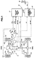
- FIG. 1 there is schematically shown essential devices and parts of a wheeled motor vehicle, to which the present invention is practically applied.
- Fig. 1 denoted by numerals 10, 20 and 30 are respectively a driving section, a braking section and a control section, which are installed in the vehicle.
- the driving section 10 comprises generally an engine 11, an automatic transmission 12, left and right front non-drive wheels 13a and 13b, left and right rear drive wheels 14a and 14b and a rear wheel differential gear 15.
- the engine 11 has in its intake system a throttle valve 16a which is controlled by an accelerator pedal 16b actuated by a driver.
- the rear drive wheels 14a and 14b are driven by the engine 11 through the transmission 12.
- the transmission 12 is of a known type generally comprising a torque converter and planetary gear units.
- the braking section 20 comprises generally a brake pedal 21 actuated by the driver, a hydraulic master cylinder 22 actuated by the brake pedal 21, an electric actuator 23, brake cylinders 25a, 25b, 25c and 25d for the wheels 13a, 13b, 14a and 14b, and connecting pipes 24a, 24b and 24c for connecting the actuator 23 with the brake cylinders 25a, 25b, 25c and 25d in the illustrated manner.
- the control section 30 comprises generally an anti-lock brake control unit 31, a brake switch 32 controlled by the brake pedal 21, rotation speed sensors 33a and 33b for the left and right front non-drive wheels 13a and 13b, a rotation speed sensor 34 for the rear drive wheels 14a and 14b, an automatic transmission control unit 35, a shift lever 36 and a gear position sensor 37 Installed in the transmission.
- the rotation speed sensors 33a, 33b and 34 issue rotation speed signals "SP-a”, “SP-b” and “SP-c” representing the rotation speeds of the corresponding wheels 13a, 13b and 14a (or 14b).
- the brake switch 32 issues a brake-ON signal “BR-ON” representing depression of the brake pedal 21.
- the brake switch 32 issues a brake-OFF signal “BR-OFF” representing non-depression of the brake pedal 21.
- the control unit 31 judges and determines a locked condition of each wheel 13a, 13b, 14a or 14b and feeds the electric actuator 23 with instruction signals "INST-BR" to control the hydraulic pressure fed to each brake cylinder 25a, 25b, 25c or 25d. With this, undesired lock of the wheels 13a, 13b, 14a and 14b upon hard depression of the brake pedal 21 is suppressed or minimized.
- the shift lever 36 when, during cruising of the vehicle, the shift lever 36 is moved to a new position thereby feeding a selected gear signal "SG" to the automatic transmission control unit 35, the unit 35 feeds the transmission 12 with a corresponding instruction signal to allow the same to carry out up-shifting or down-shifting with reference to a running condition of the vehicle.
- up-shifting of the transmission 12 is effected not only when the anti-lock brake system is actuated upon depression of the brake pedal 21, but also when the rear drive wheels 14a and 14b undergo a locked condition due to reasons other than the brake depression, that is, due to engine braking caused by a shift down operation and/or decreasing of the throttle valve opening.
- the anti-lock brake control unit 31 judges and determines a locked condition of the rear drive wheels 14a and 14b and feeds the automatic transmission control unit 35 with a lock signal "LOCK” representing locked condition of the rear drive wheels 14a and 14b. It is now to be noted that since, in this case, the brake pedal 21 is not depressed, the anti-lock brake control unit 31 does not feed the electric actuator 23 with instruction signals, and thus the anti-lock brake system does not operate.
- the automatic transmission control unit 35 Upon receiving and processing the lock signal "LOCK” from the anti-lock brake control unit 31 and a gear position signal “GP” from the gear position sensor 37, the automatic transmission control unit 35 feeds the transmission 12 with an up-instruction signal "UP-INST” to force the transmission 12 to carry out an up-shifting.
- step 40 judgment is carried out as to whether the brake pedal 21 is depressed or not. If YES, that is, when the brake pedal 21 is depressed, the operation ends. While, if NO, that is, when the brake pedal 21 is not depressed, the operation flow goes to step 41.
- step 41 judgement is carried out as to whether the lock signal "LOCK” is issued from the anti-lock brake control unit 31 or not. If YES, that is, when "LOCK” signal is issued, the operation flow goes to step 42. If NO at step 41, the operation ends. At step 42, judgement is carried out as to whether the lock signal "LOCK” is continuously issued for a given time or not.
- step 43 judging that the rear drive wheels 14a and 14b have undergone a locked condition. If NO at step 42, the operation ends.
- step 43 the above-mentioned up-instruction signal "UP-INST" is led to the transmission 12 to force the transmission 12 to carry out an up-shifting.
- the given time at step 42 should be no longer than 1 seconds, preferably from approximately 50 milliseconds to approximately 100 milliseconds. With this very short time, after occurrence of locked condition of the drive wheels 14a and 14b, up-shifting of the transmission 12 is instantly carried out, which assures keeping of the running stability of the vehicle.
- the anti-lock brake control unit 31 and the automatic transmission control unit 35 may be united as a single control unit.
- the automatic transmission 12 may be of a continuously variable type, such as V-belt type continuously variable transmission, toroidal type continuously variable transmission or the like.
- a control system for an automatic transmission installed in a motor vehicle equipped with an engine and at least one drive wheel driven by the engine through the transmission.
- the control system comprises first means which detects a locked condition of the drive wheel which is caused by engine brake, and second means which shifts up the transmission to reduce a transmission ratio thereof when actuated due to detection of the drive wheel locked condition by the first means.
- a control system for an automatic transmission installed in a motor vehicle.
- the motor vehicle is equipped with an engine and at least one drive road wheel driven by the engine through the transmission.
- the engine is capable of generating engine brake force when the transmission is shifted down and/or a throttle valve opening is decreased.
- the control system for the automatic transmission comprises a wheel lock detector for detecting a locked condition of the drive road wheel which is caused by generation of the engine brake force; and a transmission ratio changer for shifting up the transmission when the locked condition of the drive road wheel is detected by the wheel lock detector.
Abstract
A wheeled motor vehicle is equipped with an engine, an
automatic transmission, at least one drive road wheel driven by
the engine through the transmission. A control system comprises
a first device for detecting a locked condition of the drive road
wheel which is caused by engine brake, and a second device for
shifting up the transmission to reduce a transmission ratio
thereof when actuated due to detection of the locked condition of
the drive road wheel by the first device. The first device may be
a road wheel lock detecting system employed in a known anti-lock
brake system.
Description
The contents of Japanese Patent Application 9-175761 filed
July 1, 1997 are hereby incorporated by reference.
The present invention relates in general to a control system
for controlling an automotive automatic transmission, and more
particularly to a control system for an automatic transmission
installed in a motor vehicle which is equipped with a drive wheel
lock detecting system for detecting a locked condition of drive
wheels.
For clarifying the task of the present invention, one control
system of the above-mentioned type will be briefly described,
which is disclosed in Japanese Patent First Provisional Publication
62-187643. That is, this known control system controls an
automatic transmission installed in a motor vehicle which is
equipped with an anti-lock brake system.
In the known control system, when, due to hard depression
of a brake pedal, the anti-lock brake system starts to operate,
the automatic transmission is up-shifted, that is, shifted up to a
gear position of lower transmission ratio. With this up-shifting,
the anti-lock brake system becomes to have a higher
responsibility in controlling the braking force and thus the
running stability of the vehicle is kept.
However, even the above-mentioned control system fails to
satisfy users particularly when drive wheels undergo a locked
condition during running of the vehicle, due to engine brake or
the like. That is, when, during cruising of the vehicle, the
transmission is shifted down from a higher speed gear (viz.,
lower transmission ratio) to a lower speed gear (viz., higher
transmission ratio) and/or when, during running of the vehicle
with the lower speed gear, an accelerator pedal is released, a
marked engine brake is generated causing locked condition of the
drive wheels. However, in the above-mentioned known control
system, up-shifting of the transmission is not carried out in this
locked condition. In other words, in the known control system,
up-shifting of the transmission is effected only when the anti-lock
brake system is actuated upon depression of the brake pedal.
It is therefore an object of the present invention to provide
a control system for an automatic transmission installed in a
motor vehicle equipped with a drive wheel lock detecting system
for detecting a locked condition of drive wheels, which can induce
up-shifting of the transmission when the drive wheel lock
detecting system detects the locked condition of the drive wheels.
According to the present invention, there is provided a
control system for an automatic transmission installed in a motor
vehicle equipped with a detecting system for detecting a locked
condition of drive wheels, which can induce up-shifting of the
transmission when the drive wheels undergo locked condition
because, for example, during cruising of the vehicle, the
transmission is shifted down from a higher speed gear to a lower
speed gear and/or, during running of the vehicle with the lower
speed gear, a throttle valve opening is decreased due to
releasement of an accelerator pedal or the like.
Referring to Fig. 1, there is schematically shown essential
devices and parts of a wheeled motor vehicle, to which the
present invention is practically applied.
In Fig. 1, denoted by numerals 10, 20 and 30 are
respectively a driving section, a braking section and a control
section, which are installed in the vehicle.
The driving section 10 comprises generally an engine 11,
an automatic transmission 12, left and right front non-drive
wheels 13a and 13b, left and right rear drive wheels 14a and 14b
and a rear wheel differential gear 15. The engine 11 has in its
intake system a throttle valve 16a which is controlled by an
accelerator pedal 16b actuated by a driver. As shown, the rear
drive wheels 14a and 14b are driven by the engine 11 through
the transmission 12. The transmission 12 is of a known type
generally comprising a torque converter and planetary gear units.
The braking section 20 comprises generally a brake pedal
21 actuated by the driver, a hydraulic master cylinder 22
actuated by the brake pedal 21, an electric actuator 23, brake
cylinders 25a, 25b, 25c and 25d for the wheels 13a, 13b, 14a
and 14b, and connecting pipes 24a, 24b and 24c for connecting
the actuator 23 with the brake cylinders 25a, 25b, 25c and 25d in
the illustrated manner.
The control section 30 comprises generally an anti-lock
brake control unit 31, a brake switch 32 controlled by the brake
pedal 21, rotation speed sensors 33a and 33b for the left and
right front non-drive wheels 13a and 13b, a rotation speed sensor
34 for the rear drive wheels 14a and 14b, an automatic
transmission control unit 35, a shift lever 36 and a gear position
sensor 37 Installed in the transmission.
The driving section 10, the braking section 20 and the
control section 30 and their mutual connection will be well
understood when taken in conjunction with the disclosure of US
Patent 5, 117, 934 titled "SLIP CONTROL SYSTEM FOR VEHICLE
AND ROUGH ROAD DETECTING SYSTEM" issued on June 2, 1992.
During running of the vehicle, the rotation speed sensors
33a, 33b and 34 issue rotation speed signals "SP-a", "SP-b" and
"SP-c" representing the rotation speeds of the corresponding
wheels 13a, 13b and 14a (or 14b). When a driver depresses the
brake pedal 21, the brake switch 32 issues a brake-ON signal
"BR-ON" representing depression of the brake pedal 21. While,
the driver releases the brake pedal 21, the brake switch 32 issues
a brake-OFF signal "BR-OFF" representing non-depression of the
brake pedal 21. These signals "SP-a", "SP-b", "SP-c", "BR-ON"
and "BR-OFF" are inputted to the anti-lock brake control unit 31.
By processing these signals with respect to a time, the control
unit 31 judges and determines a locked condition of each wheel
13a, 13b, 14a or 14b and feeds the electric actuator 23 with
instruction signals "INST-BR" to control the hydraulic pressure fed
to each brake cylinder 25a, 25b, 25c or 25d. With this, undesired
lock of the wheels 13a, 13b, 14a and 14b upon hard depression
of the brake pedal 21 is suppressed or minimized.
As for the gear change operation of the automatic
transmission 12, when, during cruising of the vehicle, the shift
lever 36 is moved to a new position thereby feeding a selected
gear signal "SG" to the automatic transmission control unit 35,
the unit 35 feeds the transmission 12 with a corresponding
instruction signal to allow the same to carry out up-shifting or
down-shifting with reference to a running condition of the vehicle.
In this embodiment, up-shifting of the transmission 12 is
effected not only when the anti-lock brake system is actuated
upon depression of the brake pedal 21, but also when the rear
drive wheels 14a and 14b undergo a locked condition due to
reasons other than the brake depression, that is, due to engine
braking caused by a shift down operation and/or decreasing of
the throttle valve opening.
That is, when during cruising of the vehicle the
transmission 12 is shifted down from a higher speed gear (viz.,
lower transmission ratio) to a lower speed gear (viz., higher
transmission ratio) and/or when during running with the lower
speed gear an accelerator pedal 16b is released, a marked engine
brake is generated thereby increasing a possibility of locked
condition of the rear drive wheels 14a and 14b.
By processing rotation speed signal "SP-c" issued from the
rotation speed sensor 34, the anti-lock brake control unit 31
judges and determines a locked condition of the rear drive wheels
14a and 14b and feeds the automatic transmission control unit 35
with a lock signal "LOCK" representing locked condition of the
rear drive wheels 14a and 14b. It is now to be noted that since,
in this case, the brake pedal 21 is not depressed, the anti-lock
brake control unit 31 does not feed the electric actuator 23 with
instruction signals, and thus the anti-lock brake system does not
operate.
Upon receiving and processing the lock signal "LOCK" from
the anti-lock brake control unit 31 and a gear position signal "GP"
from the gear position sensor 37, the automatic transmission
control unit 35 feeds the transmission 12 with an up-instruction
signal "UP-INST" to force the transmission 12 to carry out an up-shifting.
Programmed operation steps executed by the automatic
transmission control unit 35 will be described with reference to
the flowchart of Fig. 2.
At step 40, judgment is carried out as to whether the brake
pedal 21 is depressed or not. If YES, that is, when the brake
pedal 21 is depressed, the operation ends. While, if NO, that is,
when the brake pedal 21 is not depressed, the operation flow
goes to step 41. At step 41, judgement is carried out as to
whether the lock signal "LOCK" is issued from the anti-lock brake
control unit 31 or not. If YES, that is, when "LOCK" signal is
issued, the operation flow goes to step 42. If NO at step 41, the
operation ends. At step 42, judgement is carried out as to
whether the lock signal "LOCK" is continuously issued for a given
time or not. If YES, that is, when the lock signal "LOCK" is
continuously issued for the given time, the operation flow goes to
step 43, judging that the rear drive wheels 14a and 14b have
undergone a locked condition. If NO at step 42, the operation
ends. At step 43, the above-mentioned up-instruction signal "UP-INST"
is led to the transmission 12 to force the transmission 12
to carry out an up-shifting.
The given time at step 42 should be no longer than 1
seconds, preferably from approximately 50 milliseconds to
approximately 100 milliseconds. With this very short time, after
occurrence of locked condition of the drive wheels 14a and 14b,
up-shifting of the transmission 12 is instantly carried out, which
assures keeping of the running stability of the vehicle.
If desired, the following modifications may be adopted in
the above-mentioned embodiment.
That is, the anti-lock brake control unit 31 and the
automatic transmission control unit 35 may be united as a single
control unit. Furthermore, if desired, the automatic transmission
12 may be of a continuously variable type, such as V-belt type
continuously variable transmission, toroidal type continuously
variable transmission or the like.
As will be understood from the foregoing description, the
present invention will be summarized in the following.
That is, according to a first aspect of the invention, there is
provided a control system for an automatic transmission installed
in a motor vehicle equipped with an engine and at least one drive
wheel driven by the engine through the transmission. The
control system comprises first means which detects a locked
condition of the drive wheel which is caused by engine brake, and
second means which shifts up the transmission to reduce a
transmission ratio thereof when actuated due to detection of the
drive wheel locked condition by the first means.
According to a second aspect of the invention, there is
provided a control system for an automatic transmission installed
in a motor vehicle. The motor vehicle is equipped with an engine
and at least one drive road wheel driven by the engine through
the transmission. The engine is capable of generating engine
brake force when the transmission is shifted down and/or a
throttle valve opening is decreased. The control system for the
automatic transmission comprises a wheel lock detector for
detecting a locked condition of the drive road wheel which is
caused by generation of the engine brake force; and a
transmission ratio changer for shifting up the transmission when
the locked condition of the drive road wheel is detected by the
wheel lock detector.
Claims (6)
- In a motor vehicle which is equipped with an engine, an automatic transmission and at least one drive road wheel driven by said engine through the transmission,a control system for the automatic transmission comprising:first means for detecting a locked condition of the drive road wheel which is caused by engine brake; andsecond means for shifting up the transmission to reduce a transmission ratio thereof when actuated due to detection of the locked condition of the drive road wheel by said first means.
- A control system as claimed in Claim 1, in which said first means comprises:a rotation speed sensor for sensing the rotation speed of the drive road wheel, the rotation speed sensed by said sensor being used for detecting the locked condition of the drive road wheel;a brake operation detector for detecting whether a brake pedal of the vehicle is depressed or not; anda controller for issuing a wheel lock representing signal to actuate said second means when said rotation speed sensor senses the locked condition of the drive road wheel and said brake operation detector detects non-depression of the brake pedal.
- A control system as claimed in Claim 2, in which said second means shifts up said transmission when said wheel lock representing signal is kept issued for a predetermined time.
- A control system as claimed in Claim 3, in which said predetermined time is no longer than 1 seconds.
- In a motor vehicle which is equipped with an engine, an automatic transmission and at least one drive road wheel driven by said engine through said transmission, said engine being capable of generating engine brake force when the transmission is shifted down and/or a throttle valve opening is decreased,a control system for the automatic transmission comprising:a wheel lock detector for detecting a locked condition of the drive road wheel which is caused by generation of said engine brake force; anda transmission ratio changer for shifting up the transmission when the locked condition of the drive road wheel is detected by said wheel lock detector.
- A control system as claimed in Claim 5, in which said wheel lock detector comprises:a rotation speed sensor for sensing the rotation speed of the drive road wheel, the rotation speed sensed by said sensor being used for detecting the locked condition of the drive road wheel;a brake switch for detecting whether a brake pedal of the vehicle is depressed or not; anda controller for issuing a wheel lock representing signal to actuate said transmission ratio changer when said rotation speed sensor senses the locked condition of the drive road wheel and inhibiting the actuation of said transmission ration changer when said brake switch detects the depression of the brake pedal.
Applications Claiming Priority (2)
| Application Number | Priority Date | Filing Date | Title |
|---|---|---|---|
| JP175761/97 | 1997-07-01 | ||
| JP9175761A JPH1120514A (en) | 1997-07-01 | 1997-07-01 | Shift control device of automatic transmission for vehicle with antilock brake device |
Publications (1)
| Publication Number | Publication Date |
|---|---|
| EP0889263A1 true EP0889263A1 (en) | 1999-01-07 |
Family
ID=16001802
Family Applications (1)
| Application Number | Title | Priority Date | Filing Date |
|---|---|---|---|
| EP98112073A Withdrawn EP0889263A1 (en) | 1997-07-01 | 1998-06-30 | Control system for automatic transmission installed in motor vehicle equipped with drive road wheel lock detecting system |
Country Status (2)
| Country | Link |
|---|---|
| EP (1) | EP0889263A1 (en) |
| JP (1) | JPH1120514A (en) |
Cited By (3)
| Publication number | Priority date | Publication date | Assignee | Title |
|---|---|---|---|---|
| EP1178244A3 (en) * | 2000-08-02 | 2007-05-02 | JATCO Ltd | Shift control system for automatic transmission |
| CN114148334A (en) * | 2021-12-13 | 2022-03-08 | 安徽江淮汽车集团股份有限公司 | Speed direction detection method for automatic transmission automobile |
| CN114148334B (en) * | 2021-12-13 | 2024-04-19 | 安徽江淮汽车集团股份有限公司 | Speed direction detection method for automatic transmission automobile |
Families Citing this family (2)
| Publication number | Priority date | Publication date | Assignee | Title |
|---|---|---|---|---|
| KR20050105327A (en) * | 2004-04-28 | 2005-11-04 | 주식회사 만도 | Method of controlling vehicle |
| CN103640570B (en) * | 2013-12-05 | 2016-06-22 | 广西科技大学 | A kind of Protective device of dual-clutch automatic transmission |
Citations (4)
| Publication number | Priority date | Publication date | Assignee | Title |
|---|---|---|---|---|
| JPS62187643A (en) * | 1986-02-13 | 1987-08-17 | Toyota Motor Corp | Control unit for vehicle equipped with antiskid device |
| EP0373865A2 (en) * | 1988-12-14 | 1990-06-20 | Fuji Jukogyo Kabushiki Kaisha | Transmission ratio control system for a continuously variable transmission |
| US5056637A (en) * | 1989-12-28 | 1991-10-15 | Fuji Jukogyo Kabushiki Kaisha | System for controlling speed of an engine for a motor vehicle having a continuously variable transmission |
| US5109962A (en) * | 1989-12-28 | 1992-05-05 | Fuji Jukogyo Kabushiki Kaisha | Transmission ratio control system for a continuously variable transmission |
-
1997
- 1997-07-01 JP JP9175761A patent/JPH1120514A/en active Pending
-
1998
- 1998-06-30 EP EP98112073A patent/EP0889263A1/en not_active Withdrawn
Patent Citations (4)
| Publication number | Priority date | Publication date | Assignee | Title |
|---|---|---|---|---|
| JPS62187643A (en) * | 1986-02-13 | 1987-08-17 | Toyota Motor Corp | Control unit for vehicle equipped with antiskid device |
| EP0373865A2 (en) * | 1988-12-14 | 1990-06-20 | Fuji Jukogyo Kabushiki Kaisha | Transmission ratio control system for a continuously variable transmission |
| US5056637A (en) * | 1989-12-28 | 1991-10-15 | Fuji Jukogyo Kabushiki Kaisha | System for controlling speed of an engine for a motor vehicle having a continuously variable transmission |
| US5109962A (en) * | 1989-12-28 | 1992-05-05 | Fuji Jukogyo Kabushiki Kaisha | Transmission ratio control system for a continuously variable transmission |
Non-Patent Citations (1)
| Title |
|---|
| PATENT ABSTRACTS OF JAPAN vol. 012, no. 036 (M - 664) 3 February 1988 (1988-02-03) * |
Cited By (3)
| Publication number | Priority date | Publication date | Assignee | Title |
|---|---|---|---|---|
| EP1178244A3 (en) * | 2000-08-02 | 2007-05-02 | JATCO Ltd | Shift control system for automatic transmission |
| CN114148334A (en) * | 2021-12-13 | 2022-03-08 | 安徽江淮汽车集团股份有限公司 | Speed direction detection method for automatic transmission automobile |
| CN114148334B (en) * | 2021-12-13 | 2024-04-19 | 安徽江淮汽车集团股份有限公司 | Speed direction detection method for automatic transmission automobile |
Also Published As
| Publication number | Publication date |
|---|---|
| JPH1120514A (en) | 1999-01-26 |
Similar Documents
| Publication | Publication Date | Title |
|---|---|---|
| US5262952A (en) | Slip control system for motor vehicle | |
| US6086515A (en) | Process and system for retaining a vehicle on an inclined roadway | |
| US6409285B1 (en) | Front wheel and rear wheel interlocking brake system for motorcycle | |
| US7198335B2 (en) | Method and system for controlling regenerative braking of a four wheel drive electric vehicle | |
| US7813859B2 (en) | Automatic braking device for controlling movement of vehicle in unintended direction of the driver with target brake decreasing control | |
| JP4435976B2 (en) | Automobile steering assist method and apparatus | |
| CN101142112B (en) | Method and device for controlling the braking system of a motor vehicle | |
| US9020725B2 (en) | Brake control system and method for motor vehicles | |
| RU2243429C2 (en) | Device for electronic stabilization of vehicle | |
| KR100993137B1 (en) | Apparatus and Method for preventing a vehicle back up in a vehicle | |
| US20010018384A1 (en) | Vehicle deceleration controller | |
| CN100546853C (en) | Deceleration control device for vehicle | |
| US5527235A (en) | Transmission-controlling system | |
| EP0324553B1 (en) | Clutch actuator system for automatic/semi-automatic mechanical transmission system | |
| EP0889263A1 (en) | Control system for automatic transmission installed in motor vehicle equipped with drive road wheel lock detecting system | |
| EP1681196B1 (en) | Method for reducing slippage of the driving wheels, and apparatus | |
| JPH07215196A (en) | On-slope starting auxiliary device/using traction control system | |
| JPH08113121A (en) | On-slope starting auxiliary device | |
| JP2003336666A (en) | Method for adjusting slip of clutch arranged in automatic transmission | |
| JP3741757B2 (en) | Braking force holding device for vehicle | |
| JP3018223B2 (en) | Auxiliary brake control device for vehicle | |
| JP2000193085A (en) | Method for controlling automatic down shift of automatic transmission | |
| JP3624930B2 (en) | Slope start assist device | |
| EP1526051B1 (en) | Method, arrangement and computer program for controlling a hill hold brake | |
| JP2003502206A (en) | Apparatus and method for operating a vehicle braking device depending on driving conditions |
Legal Events
| Date | Code | Title | Description |
|---|---|---|---|
| PUAI | Public reference made under article 153(3) epc to a published international application that has entered the european phase |
Free format text: ORIGINAL CODE: 0009012 |
|
| 17P | Request for examination filed |
Effective date: 19980630 |
|
| AK | Designated contracting states |
Kind code of ref document: A1 Designated state(s): DE GB |
|
| AX | Request for extension of the european patent |
Free format text: AL;LT;LV;MK;RO;SI |
|
| AKX | Designation fees paid |
Free format text: DE GB |
|
| STAA | Information on the status of an ep patent application or granted ep patent |
Free format text: STATUS: THE APPLICATION IS DEEMED TO BE WITHDRAWN |
|
| 18D | Application deemed to be withdrawn |
Effective date: 20010103 |