EP0888992A2 - Feed table for the stepwise feeding of sheets to a sheet processing machine - Google Patents
Feed table for the stepwise feeding of sheets to a sheet processing machine Download PDFInfo
- Publication number
- EP0888992A2 EP0888992A2 EP98110529A EP98110529A EP0888992A2 EP 0888992 A2 EP0888992 A2 EP 0888992A2 EP 98110529 A EP98110529 A EP 98110529A EP 98110529 A EP98110529 A EP 98110529A EP 0888992 A2 EP0888992 A2 EP 0888992A2
- Authority
- EP
- European Patent Office
- Prior art keywords
- feed table
- pressure
- table according
- areas
- suction belts
- Prior art date
- Legal status (The legal status is an assumption and is not a legal conclusion. Google has not performed a legal analysis and makes no representation as to the accuracy of the status listed.)
- Granted
Links
Images

Classifications
-
- B—PERFORMING OPERATIONS; TRANSPORTING
- B65—CONVEYING; PACKING; STORING; HANDLING THIN OR FILAMENTARY MATERIAL
- B65H—HANDLING THIN OR FILAMENTARY MATERIAL, e.g. SHEETS, WEBS, CABLES
- B65H11/00—Feed tables
- B65H11/002—Feed tables incorporating transport belts
- B65H11/005—Suction belts
-
- B—PERFORMING OPERATIONS; TRANSPORTING
- B65—CONVEYING; PACKING; STORING; HANDLING THIN OR FILAMENTARY MATERIAL
- B65H—HANDLING THIN OR FILAMENTARY MATERIAL, e.g. SHEETS, WEBS, CABLES
- B65H2406/00—Means using fluid
- B65H2406/30—Suction means
- B65H2406/32—Suction belts
- B65H2406/322—Suction distributing means
- B65H2406/3221—Suction distributing means for variable distribution in the direction of transport
-
- B—PERFORMING OPERATIONS; TRANSPORTING
- B65—CONVEYING; PACKING; STORING; HANDLING THIN OR FILAMENTARY MATERIAL
- B65H—HANDLING THIN OR FILAMENTARY MATERIAL, e.g. SHEETS, WEBS, CABLES
- B65H2406/00—Means using fluid
- B65H2406/30—Suction means
- B65H2406/32—Suction belts
- B65H2406/322—Suction distributing means
- B65H2406/3223—Suction distributing means details of the openings in the belt, e.g. shape, distribution
Definitions
- the invention relates to a feed table for cyclical conveying of sheets to a sheet processing Machine, with a table surface over which one or more spaced apart, extending in the conveying direction and transporting the sheets Suction belts drivable in the conveying direction are guided, the suction belts being endless are and the feed table over in the takeover and Enclose deflection rollers arranged in the transfer area, as well as distributed over their entire length with continuous Suction openings are provided and the bottom the suction tapes can be pressurized.
- the holding force is different depending on the extent of the cover of the suction openings through the arch.
- the object of the invention is therefore a feed table to create of the type mentioned by which the Sheet at each point on the feed table with the optimal holding force can be held on the suction belts.
- This object is achieved in that under one or more suction belts in the conveying direction a large number of pressurizable and / or negative pressure pressures Application areas arranged are, the pressure and / or negative pressure can be controlled separately.
- This training enables the holding force with which the sheets on the suction belts are held on everyone Adjust the position of the feed table to an optimum. Doing so may require a high area Holding force in which a vacuum is applied, to suddenly reach a low holding force according to exposure areas with high negative pressure Areas of application with less Pressurized or even pressurized consequences. This is e.g. in the end area of the feed table beneficial in a side orientation should take place, which is a shift of the to be aligned Bow required while the immediately following bow still held immovable on the suction belts Need to become.
- the pressure and / or negative pressure application of the application areas can depend on their coverage be controlled by promoted sheets, so that vacuum or pressure losses due to short circuit with the atmosphere and thus a change in the holding power of the Bow on the coffin tapes is avoided.
- the application areas can be with a pressure and / or Different pressure levels can be applied to negative pressure be controllable.
- a simple design of the application areas is that the areas of exposure to arranged under the table surface pressure and / or pressurizable chambers are formed which through openings in the table surface with the bottom the suction belts are connected.
- Each application area can be controlled separately Fan for pressurizing and / or negative pressure be assigned or each area of application is via a separately controllable valve connectable to a pressure and / or vacuum source.
- the feed table shown in the figures has one On table surface 1, in the direction of conveyance 2 extending and spaced apart suction belts 3 are led, one of which is shown.
- the suction belts 3 are designed as endless suction belts 3 and enclose the feed table so that they via first deflection rollers 4 on the feed side and Delivery side of the feed table to that of the table surface 1 facing away from the bottom and there via further arranged on the supply side and delivery side Roll 5 run.
- Deflection rollers 4 and rollers 5 are at right angles to the conveying direction 2 extending axes rotatable, the discharge-side deflection rollers 4 are rotatably drivable and for a movement of the on the table surface 1 provide suction belts 3 in the conveying direction 2.
- On the underside of the table surface 1 are in the area a plurality of chambers 6 under the suction belts 3 arranged in the conveying direction 2 one behind the other Passages 7 in the table surface 1 with the bottom the suction belts 3 are connected.
- the passages 7 form areas of exposure.
- the chambers 6 are lined up directly, whereby the passages 7 have a distance from each other, the about the smallest possible scale spacing supporting scale flow from Bogen corresponds.
- a fan 8 is arranged in each chamber 6 is reversibly driven and depending on the direction of rotation generates a pressure or a negative pressure in the chamber 6. By controlling the fans 8 with higher or lower speed can be different Pressure level in the chambers 6 are generated.
- the chamber has an opening leading to the outside, whose passage cross section is variable between fully closed and fully open adjustable is. Due to the short circuit to the outside air is despite constant Speed of the fans an adjustment of the Pressure levels in the chambers possible.
- each fan 8 in the illustrated embodiment can be taught separately, is in everyone Chamber 6 separately generate a pressure or negative pressure.
Landscapes
- Delivering By Means Of Belts And Rollers (AREA)
- Sheets, Magazines, And Separation Thereof (AREA)
Abstract
Description
Die Erfindung bezieht sich auf einen Anlegetisch zum taktmäßigen Fördern von Bogen zu einer Bogen verarbeitenden Maschine, mit einer Tischoberfläche, über die ein oder mehrere im Abstand zueinander angeordnete, sich in Förderrichtung erstreckende, die Bogen transportierende Saugbänder in Förderrichtung bewegbar antreibbar geführt sind, wobei die Saugbänder endlos ausgebildet sind und den Anlegetisch über im Übernahme- und Übergabebereich angeordnete Umlenkrollen umschliessen, sowie über ihre ganze Lange verteilt mit durchgehenden Saugöffnungen versehen sind und wobei die Unterseite der Saugbänder unterdruckbeaufschlagbar ist.The invention relates to a feed table for cyclical conveying of sheets to a sheet processing Machine, with a table surface over which one or more spaced apart, extending in the conveying direction and transporting the sheets Suction belts drivable in the conveying direction are guided, the suction belts being endless are and the feed table over in the takeover and Enclose deflection rollers arranged in the transfer area, as well as distributed over their entire length with continuous Suction openings are provided and the bottom the suction tapes can be pressurized.
Bei derartigen bekannten Anlegetischen kann es aus verschiedenen Gründen bei einer Unterdruckbeaufschlagung zu einem Unterdruckverlust führen, wenn ein Teil der Saugöffnungen der Saugbänder während des Betriebs des Anlegetischs nicht durch die geförderten Bogen abgedeckt und damit verschlossen werden. Dies ist z.B. der Fall, wenn die geförderten Bogen eine geringere Breite haben, als es der Abstand zwischen den äußeren Saugbändern ist. Dabei kann es sich sowohl um Förderung im Schuppenstrom als auch um Einzelbogenförderung handeln.In such known feed tables, it can consist of different Reasons for applying a vacuum lead to a loss of pressure if part of the Suction openings of the suction belts during the operation of the Feed table not covered by the funded sheets and be closed with it. This is e.g. of the Case when the conveyed sheets have a smaller width than the distance between the outer suction belts is. It can be both funding in Scale flow as well as single sheet promotion.
Bei Einzelbogenförderung kommt es weiterhin zu einem Unterdruckverlust in den Bereichen zwischen den Bogen, in denen die Saugöffnungen der Saugbänder offenliegen.In the case of single sheet conveyance, there is still one Loss of pressure in the areas between the arches, in which the suction openings of the suction belts are exposed.
Ein hoher Unterdruckverlust tritt auch bei Förderung eines einzelnen Bogens durch die vor und hinter dem Bogen offenen Saugöffnungen auf. Der gleiche ungünstige Effekt tritt bei dem ersten und dem letzten Bogen eines Schuppenstroms auf.A high vacuum loss also occurs during delivery a single arch through the front and back of the arch open suction openings. The same inconvenient Effect occurs on the first and last sheets Scale flow.
Diese Unterdruckverluste führen zu einer Reduzierung der Kraft, mit der die Bogen an den Saugbändern gehalten werden, die so gering werden kann, daß die Bogen nicht mehr verschiebungsfrei auf den Saugbändern gehalten werden.These negative pressure losses lead to a reduction the force with which the sheets are held on the suction belts be so low that the bow no longer held on the suction belts without displacement become.
Darüberhinaus ist die Haltekraft unterschiedlich groß abhängig von dem Umfang der Abdeckung der Saugöffnungen durch die Bogen.In addition, the holding force is different depending on the extent of the cover of the suction openings through the arch.
Aufgabe der Erfindung ist es daher einen Anlegetisch der eingangs genannten Art zu schaffen, durch den die Bogen an jeder Stelle des Anlegetischs mit der jeweils optimalen Haltekraft auf den Saugbändern gehalten werden. The object of the invention is therefore a feed table to create of the type mentioned by which the Sheet at each point on the feed table with the optimal holding force can be held on the suction belts.
Diese Aufgabe wird erfindungsgemäß dadurch gelöst, daS unter einem oder mehreren Saugbändern in Förderrichtung hintereinander eine Vielzahl druck- und/oder unterdruckbeaufschlagbare Beaufschlagungsbereiche angeordnet sind, deren Durck- und/oder Unterdruckbeaufschlagungung separat voneinander ansteuerbar ist.This object is achieved in that under one or more suction belts in the conveying direction a large number of pressurizable and / or negative pressure pressures Application areas arranged are, the pressure and / or negative pressure can be controlled separately.
Diese Ausbildung ermöglicht es die Haltekraft, mit der die Bogen auf den Saugbändern gehalten werden an jeder Stelle des Anlegetischs auf ein Optimum einzustellen. Dabei können nach einem Bereich hoher erforderlicher Haltekraft, in dem eine Unterdruckbeaufschlagung erfolgt, zum plötzlichen Erreichen einer geringen Haltekraft nach Beaufschlagungsbereichen mit hoher Unterdruckbeaufschlagung Beaufschlagungsbereiche mit geringer Unterdruckbeaufschlagung oder sogar mit Druckbeaufschlagung folgen. Dies ist z.B. im Endbereich des Anlegetischs von Vorteil, in dem eine Seitenausrichtung erfolgen soll, die ein Verschieben der auzurichtenden Bogen erfordert, während die unmittelbar folgenden Bogen noch unverschiebbar auf den Saugbändern gehalten werden müssen.This training enables the holding force with which the sheets on the suction belts are held on everyone Adjust the position of the feed table to an optimum. Doing so may require a high area Holding force in which a vacuum is applied, to suddenly reach a low holding force according to exposure areas with high negative pressure Areas of application with less Pressurized or even pressurized consequences. This is e.g. in the end area of the feed table beneficial in a side orientation should take place, which is a shift of the to be aligned Bow required while the immediately following bow still held immovable on the suction belts Need to become.
Auch eine Variation der Druck- und/oder Unterdruckbeaufschlagung in Abhängigkeit der Bogenqualität der jeweils verarbeiteten Bogen ist möglich. So benötigen leichte Bogen eine andere Haltekraft als Bogen grösserer Steifigkeit. Auch ist bei Bogen großer Luftdurchlässigkeit ein anderes Unterdruckniveau sinnvoll als bei Bogen geringer Luftdurchlässigkeit.Also a variation of the pressure and / or negative pressure depending on the sheet quality of each processed bow is possible. So need it light arches have a different holding force than arches larger Stiffness. There is also great air permeability with bows a different vacuum level makes sense than for sheets with low air permeability.
Ungewollte Unterdruckverluste bei dem ersten und dem letzten Bogen werden durch die erfindungsgemäße Ausbildung ebenfalls vermieden, da kein Kurzschluß der aktiven Beaufschlagungsbereiche zur Atmosphäre erfolgt.Unintended negative pressure losses with the first and the last bow are through the inventive training also avoided since there is no short circuit of the active Areas of exposure to the atmosphere occur.
Die Druck- und/oder Unterdruckbeaufschlagung der Beaufschlagungsbereiche kann in Abhängigkeit ihrer Abdeckung durch geförderte Bogen ansteuerbar sein, sodaß Unterdruck- oder Druckverluste durch Kurzschluß mit der Atmosphäre und damit eine Veränderung der Haltekraft der Bogen auf den Sarngbändern vermieden wird.The pressure and / or negative pressure application of the application areas can depend on their coverage be controlled by promoted sheets, so that vacuum or pressure losses due to short circuit with the atmosphere and thus a change in the holding power of the Bow on the coffin tapes is avoided.
Darüberhinaus wird die für die Erzeugung des Drucks oder des Unterdrucks aufzubringende Energie auf das mindest erforderliche Maß reduziert.In addition, it is used for generating the pressure or the energy to be applied to the vacuum minimum required size reduced.
Verändern sich durch die Förderbewegung der Bogen die von den Bogen abgedeckten und nicht abgedeckten Beaufschlagungsbereiche, so kann eine permanent sich ändern-de Ansteuerung der Beaufschlagung der Beaufschlagungsbereiche erfolgen, sodaß immer nur die gerade von einem Bogen abgedeckten Beaufschlagungsbereiche mit Druck- oder Unterdruck beaufschlagt werden. Dies ist z.B. auch am Anfang und am Ende eines Bogenstromes von Vorteil.Change through the conveying movement of the bow areas of exposure covered and not covered by the arches, so one can change permanently Control of the application of the application areas done, so that only the one Arc covered areas with pressure or Vacuum can be applied. This is e.g. also an advantage at the beginning and at the end of an arc stream.
Die Beaufschlagungsbereiche können mit einem Druck- und/oder Unterdruck unterschiedlichen Druckniveaus beaufschlagbar ansteuerbar sein.The application areas can be with a pressure and / or Different pressure levels can be applied to negative pressure be controllable.
Um bei Förderung im Schuppenstrom jeden Bogen an jeder Stelle des Transportwegs mit seiner optimalen Haltekraft auf den Saugbändern zu halten, können die Beaufschlagungsbereiche mit einem etwa einem Schuppenabstand eines zu fördernden Schuppenstroms von Bogen entsprechenden Abstand angeordnet sein.In order to convey every bend to everybody in the shingled stream Place of the transport route with its optimal holding force Keeping them on the suction belts can affect the exposure areas with about a scale distance of a scale stream to be conveyed from Bogen corresponding Distance must be arranged.
Will man dabei in Schruppenströmen unterschiedlichen Schuppenabstands fördern können, so können die Beaufschlagungsbereiche mit einem etwa einem geringst möglichen Schuppenabstand eines zu fördernden Schuppenstroms entsprechenden Abstand von Bogen angeordnet sein.If you want different in roughing streams Can promote scale spacing, so the impact areas with about the least possible Scale distance of a scale flow to be conveyed appropriate distance from the arc be.
Bei einem Anlegetisch für Einzelbogenförderung sind vorzugsweise die Beaufschlagungsbereiche mit einem einem Bogenabstand eines zu fördernden Einzelbogenstroms entsprechenden Abstand zueinander angeordnet.At a feed table for single sheet conveyance preferably the application areas with a an arc distance of a single arc stream to be conveyed appropriate distance from each other.
Natürlich ist es durch die erfindungsgemäße Ausbildung grundsätzlich möglich sowohl im Schuppenstrom als auch im Einzelbogenstrom zu fördern.Of course it is due to the training according to the invention basically possible both in the shingled stream and to promote in single sheet flow.
Um die einzelnen Beaufschlagungsbereiche exakt und rasch wechseln ansteuern zu können, kann jedem Beaufschlagungsbereich ein Druck- und/oder Unterdruckerzeuger zugeordnet sein. Damit wird auch das Volumen, welches unter Unterdurck- oder Druck gesetzt werden soll, gering gehalten und somit der Druck- oder Unterdruck schnell auf- bzw. abbaubar.To the individual application areas exactly and Being able to switch quickly to any application area a pressure and / or vacuum generator be assigned. So that also the volume, which are put under pressure or pressure should be kept low and thus the pressure or vacuum can be assembled and disassembled quickly.
Eine einfache Ausgestaltung der Beaufschlagungsbereiche besteht darin, daß die Beaufschlagungsbereiche durch unter der Tischoberfläche angeordnete druck- und/oder unterdruckbeaufschlagbare Kammern gebildet sind, die über Durchlässe in der Tischoberfläche mit der Unterseite der Saugbänder verbunden sind.A simple design of the application areas is that the areas of exposure to arranged under the table surface pressure and / or pressurizable chambers are formed which through openings in the table surface with the bottom the suction belts are connected.
Dabei kann jedem Beaufschlagungsbereich ein separat ansteuerbarer Ventilator zur Druck- und/oder Unterdruckbeaufschlagung zugeordnet sein oder jeder Beaufschlagungsbereich ist über ein separat ansteuerbares Ventil mit einer Druck- und/oder Unterdruckquelle verbindbar.Each application area can be controlled separately Fan for pressurizing and / or negative pressure be assigned or each area of application is via a separately controllable valve connectable to a pressure and / or vacuum source.
Ein Ausführungsbeispiel der Erfindung ist in der Zeichnung dargestellt und wird im folgenden näher beschrieben. Es zeigen
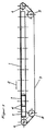
- Figur 1
- eine Seitenansicht eines Anlegetischs
- Figur 2
- eine Draufsicht eines Teils des Anlegetischs nach Figur 1.
- Figure 1
- a side view of a feed table
- Figure 2
- a plan view of part of the feed table of Figure 1.
Der in den Figuren dargestellte Anlegetisch weist eine
Tischoberfläche 1 auf, über die in Förderrichtung 2
sich erstreckend und im Abstand zueinander Saugbänder 3
geführt sind, von denen eines dargestellt ist.The feed table shown in the figures has one
On table surface 1, in the direction of conveyance 2
extending and spaced apart
Die Saugbänder 3 sind als endlose Saugbänder 3 ausgebildet
und umschließen derart den Anlegetisch, daß sie
über erste Umlenkrollen 4 an der Zufuhrseite und der
Abgabeseite des Anlegetischs zu dessen der Tischoberfläche
1 abgewandten Unterseite geführt sind und dort
über weitere zufuhrseitig und abgabeseitig angeordnete
Rollen 5 laufen.The
Umlenkrollen 4 und Rollen 5 sind um quer zur Förderrichtung
2 sich erstreckende Achsen drehbar, wobei die
abgabeseitigen Umlenkrollen 4 drehbar antreibbar sind
und für eine Bewegung der auf der Tischoberfläche 1
aufliegenden Saugbänder 3 in Förderrichtung 2 sorgen.
Auf der Unterseite der Tischoberfläche 1 sind im Bereich
unter den Saugbändern 3 eine Vielzahl Kammern 6
in Förderrichtung 2 hintereinander angeordnet, die über
Durchlässe 7 in der Tischoberfläche 1 mit der Unterseite
der Saugbänder 3 verbunden sind. Die Durchlässe 7
bilden dabei Beaufschlagungsbereiche.
Die Kammern 6 sind unmittelbar aneinandergereiht, wobei
die Durchlässe 7 einen Abstand zueinander besitzen, der
etwa einem geringst möglichen Schuppenabstand eines zu
fördernden Schuppenstroms von Bogen entspricht.The
In jeder Kammer 6 ist ein Ventilator 8 angeordnet, der
reversierbar antreibbar ist und je nach Drehrichtung
einen Druck oder einen Unterdruck in der Kammer 6 erzeugt.
Über eine Ansteuerung der Ventilatoren 8 mit
höherer oder niedrigerer Drehzahl kann ein unterschiedliches
Druckniveau in den Kammern 6 erzeugt werden.A
Eine andere Möglichkeit zur Erzeugung eines unterschiedlichen Druckniveaus in der Kammer besteht darin, daß die Kammer eine nach außen führende Öffnung aufweist, deren Durchgangsquerschnitt variabel zwischen völlig geschlossen und vollständig geöffnet einstellbar ist. Durch den Kurzschluß zur Außenluft ist trotz konstanter Drehzahl der Ventilatoren eine Einstellung des Druckniveaus in den Kammern möglich.Another way to create a different one Pressure levels in the chamber is that the chamber has an opening leading to the outside, whose passage cross section is variable between fully closed and fully open adjustable is. Due to the short circuit to the outside air is despite constant Speed of the fans an adjustment of the Pressure levels in the chambers possible.
Da jeder Ventilator 8 bei dem dargestellten Ausführungsbeispiel
separat ansternerbar ist, ist in jeder
Kammer 6 separat ein Druck oder Unterdruck erzeugbar.Since each
Durch durchgehende Saugöffnungen 9 in den Saugbändern
3, die über die ganze Länge der Saugbänder 3 ausgebildet
sind, wird der in den Kammern 6 erzeugte Druck oder
Unterdruck auf die Oberseite der Saugbänder 6 geführt
und dient dort zum Erfassen und Halten der zu fördernden
Bogen auf den Saugbändern. Through
- 11
- TischoberflächeTable surface
- 22nd
- FörderrichtungDirection of conveyance
- 33rd
- SaugbänderSuction belts
- 44th
- UmlenkrollenPulleys
- 55
- Rollenroll
- 66
- KammernChambers
- 77
- DurchlässeCulverts
- 88th
- Ventilatorfan
- 99
- SaugöffnungenSuction openings
Claims (10)
Applications Claiming Priority (2)
| Application Number | Priority Date | Filing Date | Title |
|---|---|---|---|
| DE19728056 | 1997-07-01 | ||
| DE19728056A DE19728056A1 (en) | 1997-07-01 | 1997-07-01 | Feed table for the cyclical conveying of sheets to a sheet processing machine |
Publications (3)
| Publication Number | Publication Date |
|---|---|
| EP0888992A2 true EP0888992A2 (en) | 1999-01-07 |
| EP0888992A3 EP0888992A3 (en) | 1999-04-14 |
| EP0888992B1 EP0888992B1 (en) | 2002-09-04 |
Family
ID=7834300
Family Applications (1)
| Application Number | Title | Priority Date | Filing Date |
|---|---|---|---|
| EP98110529A Expired - Lifetime EP0888992B1 (en) | 1997-07-01 | 1998-06-09 | Feed table for the stepwise feeding of sheets to a sheet processing machine |
Country Status (4)
| Country | Link |
|---|---|
| EP (1) | EP0888992B1 (en) |
| JP (1) | JP3155245B2 (en) |
| AT (1) | ATE223345T1 (en) |
| DE (2) | DE19728056A1 (en) |
Cited By (3)
| Publication number | Priority date | Publication date | Assignee | Title |
|---|---|---|---|---|
| WO2000061478A1 (en) * | 1999-04-09 | 2000-10-19 | Profold, Inc. | Vacuum table conveying apparatus and associated methods |
| EP3221221B1 (en) | 2014-11-19 | 2019-03-20 | Bobst Mex Sa | Device for optically controlling a face of a blank, blank treatment machine and folder-gluer comprising said device |
| US10781047B2 (en) | 2016-09-16 | 2020-09-22 | Bruks Rockwood, Llc | Air-supported belt conveyors and systems and methods of using same |
Families Citing this family (15)
| Publication number | Priority date | Publication date | Assignee | Title |
|---|---|---|---|---|
| DE10162444B4 (en) * | 2001-02-06 | 2008-06-26 | Heidelberger Druckmaschinen Ag | Device for simultaneous suction and transport of a sheet |
| DE10213705C5 (en) | 2001-04-26 | 2017-01-05 | Heidelberger Druckmaschinen Ag | Apparatus for conveying a sheet flow from a sheet stack to a sheet processing machine |
| EP2093068B1 (en) | 2001-10-17 | 2012-05-16 | Seiko Epson Corporation | A transporting apparatus and a recording apparatus comprising the same |
| JP3783602B2 (en) * | 2001-10-17 | 2006-06-07 | セイコーエプソン株式会社 | RECORDING MEDIUM CONVEYING DEVICE AND RECORDING DEVICE HAVING RECORDING MEDIUM CONVEYING DEVICE |
| DE102006033940A1 (en) * | 2006-07-22 | 2008-01-24 | Koenig & Bauer Aktiengesellschaft | Apparatus for feeding a scaly arc stream |
| DE102006061429B4 (en) * | 2006-12-23 | 2023-07-20 | Koenig & Bauer Ag | Method of feeding a shingled arc stream |
| DE102006061399B4 (en) * | 2006-12-23 | 2023-06-22 | Koenig & Bauer Ag | Method of feeding a shingled arc stream |
| JP2009028917A (en) * | 2007-07-24 | 2009-02-12 | Seiko Epson Corp | Recorder and liquid jet apparatus |
| JP5152980B2 (en) * | 2008-05-27 | 2013-02-27 | 富士フイルム株式会社 | Inkjet recording apparatus and method |
| DE102009048928A1 (en) | 2009-10-10 | 2011-04-14 | Steinemann Technology Ag | Inkjet printer for printing on sheet-shaped substrate, has printing unit transport device including conveyor belt with drive device that impresses speed to belt, where printing sheet or substrate is provided with certain distance to belt |
| JP5538874B2 (en) * | 2009-12-25 | 2014-07-02 | キヤノン株式会社 | Image forming apparatus |
| WO2012102381A1 (en) * | 2011-01-27 | 2012-08-02 | 三菱重工印刷紙工機械株式会社 | Aligning/transferring apparatus, electronic printer, printer, and aligning/transferring method |
| JP6259279B2 (en) * | 2013-03-11 | 2018-01-10 | 株式会社小森コーポレーション | Sheet feeding device |
| JP6865000B2 (en) * | 2016-08-25 | 2021-04-28 | 理想科学工業株式会社 | Sheet transfer device |
| DE102019126657B4 (en) * | 2019-10-02 | 2021-06-02 | Böwe Systec Gmbh | Separating device and method for separating thin sheet units from a stack of sheets by means of a separating device |
Citations (6)
| Publication number | Priority date | Publication date | Assignee | Title |
|---|---|---|---|---|
| US3827548A (en) * | 1972-09-11 | 1974-08-06 | M Matsuo | Belt conveyor for sheet material |
| US4645069A (en) * | 1985-11-12 | 1987-02-24 | Quipp, Incorporated | Vacuum accumulating conveyor |
| EP0453790A1 (en) * | 1990-04-24 | 1991-10-30 | MAN Roland Druckmaschinen AG | Device for conveying sheets |
| GB2289042A (en) * | 1994-05-07 | 1995-11-08 | Heidelberger Druckmasch Ag | Sheet conveyor |
| DE4442629A1 (en) * | 1994-12-01 | 1996-06-05 | Heidelberger Druckmasch Ag | Suction band feed table for sheets of paper |
| EP0776846A2 (en) * | 1995-11-30 | 1997-06-04 | Xerox Corporation | An acquisition levitation transport device |
Family Cites Families (1)
| Publication number | Priority date | Publication date | Assignee | Title |
|---|---|---|---|---|
| US4213604A (en) * | 1977-07-19 | 1980-07-22 | Canon Kabushiki Kaisha | Automatic original handling device |
-
1997
- 1997-07-01 DE DE19728056A patent/DE19728056A1/en not_active Withdrawn
-
1998
- 1998-06-09 DE DE59805382T patent/DE59805382D1/en not_active Expired - Fee Related
- 1998-06-09 EP EP98110529A patent/EP0888992B1/en not_active Expired - Lifetime
- 1998-06-09 AT AT98110529T patent/ATE223345T1/en not_active IP Right Cessation
- 1998-07-01 JP JP18605398A patent/JP3155245B2/en not_active Expired - Fee Related
Patent Citations (6)
| Publication number | Priority date | Publication date | Assignee | Title |
|---|---|---|---|---|
| US3827548A (en) * | 1972-09-11 | 1974-08-06 | M Matsuo | Belt conveyor for sheet material |
| US4645069A (en) * | 1985-11-12 | 1987-02-24 | Quipp, Incorporated | Vacuum accumulating conveyor |
| EP0453790A1 (en) * | 1990-04-24 | 1991-10-30 | MAN Roland Druckmaschinen AG | Device for conveying sheets |
| GB2289042A (en) * | 1994-05-07 | 1995-11-08 | Heidelberger Druckmasch Ag | Sheet conveyor |
| DE4442629A1 (en) * | 1994-12-01 | 1996-06-05 | Heidelberger Druckmasch Ag | Suction band feed table for sheets of paper |
| EP0776846A2 (en) * | 1995-11-30 | 1997-06-04 | Xerox Corporation | An acquisition levitation transport device |
Cited By (7)
| Publication number | Priority date | Publication date | Assignee | Title |
|---|---|---|---|---|
| WO2000061478A1 (en) * | 1999-04-09 | 2000-10-19 | Profold, Inc. | Vacuum table conveying apparatus and associated methods |
| US6216848B1 (en) | 1999-04-09 | 2001-04-17 | Profold, Inc. | Vacuum table conveying apparatus and associated methods |
| EP3221221B1 (en) | 2014-11-19 | 2019-03-20 | Bobst Mex Sa | Device for optically controlling a face of a blank, blank treatment machine and folder-gluer comprising said device |
| EP3221221B2 (en) † | 2014-11-19 | 2024-03-06 | Bobst Mex Sa | Device for optically controlling a face of a blank, blank treatment machine and folder-gluer comprising said device |
| US10781047B2 (en) | 2016-09-16 | 2020-09-22 | Bruks Rockwood, Llc | Air-supported belt conveyors and systems and methods of using same |
| US10947047B2 (en) | 2016-09-16 | 2021-03-16 | Bruks Rockwood, Llc | Air-supported belt conveyors and systems and methods of using same |
| US11420824B2 (en) | 2016-09-16 | 2022-08-23 | Bruks Rockwood, Llc | Air-supported belt conveyors and systems and methods of using same |
Also Published As
| Publication number | Publication date |
|---|---|
| EP0888992B1 (en) | 2002-09-04 |
| DE19728056A1 (en) | 1999-01-07 |
| JPH1171042A (en) | 1999-03-16 |
| ATE223345T1 (en) | 2002-09-15 |
| DE59805382D1 (en) | 2002-10-10 |
| JP3155245B2 (en) | 2001-04-09 |
| EP0888992A3 (en) | 1999-04-14 |
Similar Documents
| Publication | Publication Date | Title |
|---|---|---|
| EP0888992A2 (en) | Feed table for the stepwise feeding of sheets to a sheet processing machine | |
| EP0075685B1 (en) | Device for conveying a progression of overlapping sheets of paper | |
| DE4242730C2 (en) | Sheet delivery of a printing press | |
| DE4013302A1 (en) | DEVICE FOR PROMOTING A PARTICULAR DIVIDED FLOW FROM ARC | |
| EP0559846B1 (en) | Device for turning a sheet with a simultaneous change in the direction of transport | |
| EP1593628B1 (en) | Device for simultaneously feeding and aligning sheets | |
| DE2411238A1 (en) | METHOD AND DEVICE FOR GUIDING THE BEGINNING OF A MATERIAL TRAIL | |
| DE3838078C3 (en) | Device for conveying a flow of sheets | |
| DE202004006615U1 (en) | Device for a conveyor table used for transporting sheet material in a sheet-fed rotary printing machine comprises transport belts, and a blowing device blowing air below the sheets in guide regions via ventilation openings | |
| DE102004030277B4 (en) | Device for conveying sheets by a printing machine | |
| DE29924658U1 (en) | Device for conveying and guiding an infeed strip of a web in a paper machine | |
| DE3001652C2 (en) | Suction channel of a conveyor | |
| DE2915371C2 (en) | Device for separating the sheets of a stack of paper | |
| DE69817310T2 (en) | Apparatus and method for separating sheets from a stack of sheets | |
| EP0844081A1 (en) | Method and apparatus for powdering products, in particular printed products | |
| DE1931208C3 (en) | Device for conveying and depositing sheets of paper and other sheet material in stacks | |
| DE3234155A1 (en) | Device for guiding a sheet and for holding it down in the transport plane of a printing press | |
| DE3527277C2 (en) | Stacking device for stacking sheets while feeding the sheets at the bottom of the stack | |
| DE4012943A1 (en) | System for overlapping successively moved sheets - has air blasts designed to allow overlap | |
| DE102008049809A1 (en) | Sheet conveying device for use in e.g. sheet separating device, has constant pressure controller in air line for maintain constant pressure differential between interior space of air line and air line environment | |
| DD252173A1 (en) | DEVICE FOR ROLLING AND ALIGNING ARC | |
| DE9004967U1 (en) | Device for conveying a particularly shingled stream of sheets | |
| EP1792861B1 (en) | Vacuum belt feeding apparatus for guiding a moving web | |
| DE19523363A1 (en) | Continuous laying process for individual sheets e.g. on carrier track to belt press | |
| DE10059391A1 (en) | Output stacker for printing machine has air nozzles which point forwards at angle so that sheets are blown down against front edge stop |
Legal Events
| Date | Code | Title | Description |
|---|---|---|---|
| PUAI | Public reference made under article 153(3) epc to a published international application that has entered the european phase |
Free format text: ORIGINAL CODE: 0009012 |
|
| AK | Designated contracting states |
Kind code of ref document: A2 Designated state(s): AT DE FR GB IT |
|
| AX | Request for extension of the european patent |
Free format text: AL;LT;LV;MK;RO;SI |
|
| PUAL | Search report despatched |
Free format text: ORIGINAL CODE: 0009013 |
|
| AK | Designated contracting states |
Kind code of ref document: A3 Designated state(s): AT BE CH CY DE DK ES FI FR GB GR IE IT LI LU MC NL PT SE |
|
| AX | Request for extension of the european patent |
Free format text: AL;LT;LV;MK;RO;SI |
|
| 17P | Request for examination filed |
Effective date: 19990317 |
|
| 17Q | First examination report despatched |
Effective date: 19990625 |
|
| AKX | Designation fees paid |
Free format text: AT BE CH CY DE LI |
|
| RBV | Designated contracting states (corrected) |
Designated state(s): AT DE FR GB IT |
|
| GRAG | Despatch of communication of intention to grant |
Free format text: ORIGINAL CODE: EPIDOS AGRA |
|
| GRAG | Despatch of communication of intention to grant |
Free format text: ORIGINAL CODE: EPIDOS AGRA |
|
| GRAH | Despatch of communication of intention to grant a patent |
Free format text: ORIGINAL CODE: EPIDOS IGRA |
|
| GRAH | Despatch of communication of intention to grant a patent |
Free format text: ORIGINAL CODE: EPIDOS IGRA |
|
| GRAA | (expected) grant |
Free format text: ORIGINAL CODE: 0009210 |
|
| AK | Designated contracting states |
Kind code of ref document: B1 Designated state(s): AT DE FR GB IT |
|
| PG25 | Lapsed in a contracting state [announced via postgrant information from national office to epo] |
Ref country code: IT Free format text: LAPSE BECAUSE OF FAILURE TO SUBMIT A TRANSLATION OF THE DESCRIPTION OR TO PAY THE FEE WITHIN THE PRE;WARNING: LAPSES OF ITALIAN PATENTS WITH EFFECTIVE DATE BEFORE 2007 MAY HAVE OCCURRED AT ANY TIME BEFORE 2007. THE CORRECT EFFECTIVE DATE MAY BE DIFFERENT FROM THE ONE RECORDED.SCRIBED TIME-LIMIT Effective date: 20020904 |
|
| REF | Corresponds to: |
Ref document number: 223345 Country of ref document: AT Date of ref document: 20020915 Kind code of ref document: T |
|
| REG | Reference to a national code |
Ref country code: GB Ref legal event code: FG4D Free format text: NOT ENGLISH |
|
| GBT | Gb: translation of ep patent filed (gb section 77(6)(a)/1977) |
Effective date: 20020904 |
|
| REF | Corresponds to: |
Ref document number: 59805382 Country of ref document: DE Date of ref document: 20021010 |
|
| ET | Fr: translation filed | ||
| PLBE | No opposition filed within time limit |
Free format text: ORIGINAL CODE: 0009261 |
|
| STAA | Information on the status of an ep patent application or granted ep patent |
Free format text: STATUS: NO OPPOSITION FILED WITHIN TIME LIMIT |
|
| 26N | No opposition filed |
Effective date: 20030605 |
|
| PGFP | Annual fee paid to national office [announced via postgrant information from national office to epo] |
Ref country code: AT Payment date: 20080616 Year of fee payment: 11 |
|
| PGFP | Annual fee paid to national office [announced via postgrant information from national office to epo] |
Ref country code: DE Payment date: 20080620 Year of fee payment: 11 |
|
| PGFP | Annual fee paid to national office [announced via postgrant information from national office to epo] |
Ref country code: FR Payment date: 20080613 Year of fee payment: 11 |
|
| PGFP | Annual fee paid to national office [announced via postgrant information from national office to epo] |
Ref country code: GB Payment date: 20080620 Year of fee payment: 11 |
|
| REG | Reference to a national code |
Ref country code: FR Ref legal event code: CD |
|
| GBPC | Gb: european patent ceased through non-payment of renewal fee |
Effective date: 20090609 |
|
| REG | Reference to a national code |
Ref country code: FR Ref legal event code: ST Effective date: 20100226 |
|
| PG25 | Lapsed in a contracting state [announced via postgrant information from national office to epo] |
Ref country code: FR Free format text: LAPSE BECAUSE OF NON-PAYMENT OF DUE FEES Effective date: 20090630 |
|
| PG25 | Lapsed in a contracting state [announced via postgrant information from national office to epo] |
Ref country code: GB Free format text: LAPSE BECAUSE OF NON-PAYMENT OF DUE FEES Effective date: 20090609 |
|
| PG25 | Lapsed in a contracting state [announced via postgrant information from national office to epo] |
Ref country code: DE Free format text: LAPSE BECAUSE OF NON-PAYMENT OF DUE FEES Effective date: 20100101 Ref country code: AT Free format text: LAPSE BECAUSE OF NON-PAYMENT OF DUE FEES Effective date: 20090609 |