EP0887543B1 - Spring clip for retaining a fuel injector in a fuel rail cup - Google Patents
Spring clip for retaining a fuel injector in a fuel rail cup Download PDFInfo
- Publication number
- EP0887543B1 EP0887543B1 EP98110989A EP98110989A EP0887543B1 EP 0887543 B1 EP0887543 B1 EP 0887543B1 EP 98110989 A EP98110989 A EP 98110989A EP 98110989 A EP98110989 A EP 98110989A EP 0887543 B1 EP0887543 B1 EP 0887543B1
- Authority
- EP
- European Patent Office
- Prior art keywords
- injector
- clip
- cup
- fuel rail
- fuel
- Prior art date
- Legal status (The legal status is an assumption and is not a legal conclusion. Google has not performed a legal analysis and makes no representation as to the accuracy of the status listed.)
- Expired - Lifetime
Links
- 239000000446 fuel Substances 0.000 title claims description 65
- 230000013011 mating Effects 0.000 claims description 2
- 238000000034 method Methods 0.000 description 4
- 230000000712 assembly Effects 0.000 description 1
- 238000000429 assembly Methods 0.000 description 1
- 230000001186 cumulative effect Effects 0.000 description 1
- 238000009434 installation Methods 0.000 description 1
- 230000014759 maintenance of location Effects 0.000 description 1
- 239000000463 material Substances 0.000 description 1
- 239000007769 metal material Substances 0.000 description 1
- 239000007921 spray Substances 0.000 description 1
- 230000008685 targeting Effects 0.000 description 1
Images
Classifications
-
- F—MECHANICAL ENGINEERING; LIGHTING; HEATING; WEAPONS; BLASTING
- F02—COMBUSTION ENGINES; HOT-GAS OR COMBUSTION-PRODUCT ENGINE PLANTS
- F02M—SUPPLYING COMBUSTION ENGINES IN GENERAL WITH COMBUSTIBLE MIXTURES OR CONSTITUENTS THEREOF
- F02M61/00—Fuel-injectors not provided for in groups F02M39/00 - F02M57/00 or F02M67/00
- F02M61/14—Arrangements of injectors with respect to engines; Mounting of injectors
- F02M61/145—Arrangements of injectors with respect to engines; Mounting of injectors the injection nozzle opening into the air intake conduit
-
- F—MECHANICAL ENGINEERING; LIGHTING; HEATING; WEAPONS; BLASTING
- F02—COMBUSTION ENGINES; HOT-GAS OR COMBUSTION-PRODUCT ENGINE PLANTS
- F02M—SUPPLYING COMBUSTION ENGINES IN GENERAL WITH COMBUSTIBLE MIXTURES OR CONSTITUENTS THEREOF
- F02M69/00—Low-pressure fuel-injection apparatus ; Apparatus with both continuous and intermittent injection; Apparatus injecting different types of fuel
- F02M69/46—Details, component parts or accessories not provided for in, or of interest apart from, the apparatus covered by groups F02M69/02 - F02M69/44
- F02M69/462—Arrangement of fuel conduits, e.g. with valves for maintaining pressure in the pipes after the engine being shut-down
- F02M69/465—Arrangement of fuel conduits, e.g. with valves for maintaining pressure in the pipes after the engine being shut-down of fuel rails
-
- F—MECHANICAL ENGINEERING; LIGHTING; HEATING; WEAPONS; BLASTING
- F02—COMBUSTION ENGINES; HOT-GAS OR COMBUSTION-PRODUCT ENGINE PLANTS
- F02M—SUPPLYING COMBUSTION ENGINES IN GENERAL WITH COMBUSTIBLE MIXTURES OR CONSTITUENTS THEREOF
- F02M2200/00—Details of fuel-injection apparatus, not otherwise provided for
- F02M2200/85—Mounting of fuel injection apparatus
- F02M2200/853—Mounting of fuel injection apparatus involving use of quick-acting mechanism, e.g. clips
Definitions
- This invention relates to the assembly of a fuel injector in a fuel rail cup and more particularly to an improved clip for retaining an associated fuel injector in a corresponding fuel rail cup against axial and relative circumferential rotation.
- One type of arrangement provides a flat portion of a lower clip groove in an injector, or a radially extending flat portion of an injector, that engages with a corresponding flat portion of the clip. This engagement with the flat portion is intended to prevent the injector from rotating to ensure correct targeting of the fuel spray. However, upon repeated turning of the injector, the flats on the injector or radially extending portion become worn away and the injector becomes misaligned.
- the spring clip includes raised tangs formed in the clip which engage a corresponding feature on the fuel injector and fuel rail cup to orient the injector in the cup.
- the application of rotational force to the injector in this arrangement has been found to cause the tangs to bend and allow the injector to become misaligned in service.
- an injector orifice is oriented relative to an electrical connector.
- the electrical connector is referenced to a clip groove in the injector and the injector clip is oriented by the clip groove.
- Features within the clip relate the clip groove location feature to the clip sides.
- the clip sides are located to a tab on the injector cup, and the injector cup is oriented to the fuel rail mounting feature, such as screw holes.
- the fuel rail is oriented to the manifold and the manifold is oriented to the head and eventually to the inlet valves, the desired target. This arrangement results in a large cumulative alignment tolerance. Location is limited by the feature easiest overcome which is the clip to clip groove interface which provides generally about 11 to 15 in.lb. of resistance torque for first time rotation. Once the injector has been rotated, the resistance to subsequent rotations drops off significantly.
- the present invention provides an improved spring clip according to claim 1 for retaining together a fuel injector and a fuel rail clip that fixes an associated fuel injector against axial and rotational movement relative to a corresponding fuel rail cup.
- the spring clip of the invention includes a key feature or aperture for receiving, and retaining therein, corresponding radially protruding keys of an injector and a fuel rail cup, which provides superior resistance to rotation of the injector in the fuel rail cup.
- the spring clip includes first and second parallel spaced side walls and a third side wall resiliently connecting the first and second side walls to form a generally U-shaped body with an open side.
- the first and second parallel spaced side walls include flanges extending inwardly toward one another from opposed lower edges of the side walls. The flanges are configured to coact with an exterior surface of an associated fuel injector to locate the injector axially relative to the clip.
- the first and second parallel spaced side walls also include slots arranged to receive a flanged portion of the fuel rail cup such that the clip is located axially relative to the cup, thereby locating said injector axially relative to the cup.
- An aperture in the third side wall receives both a radially protruding orientation key of the injector and a corresponding orientation key of the fuel rail cup.
- the clip When the injector is assembled in the fuel rail cup, the clip may be snapped onto the assembly to fix the injector against axial and rotational movement relative to the fuel rail cup.
- the clip is designed so that it may be first mounted on the injector in its proper position. Then the injector with the clip attached is inserted into the fuel rail cup and the clip snaps over the cup flanges while its radially protruding key is guided into the orienting aperture of the spring clip. This mode of installation is made possible by outwardly angled upper positions of the three side walls of the clip.
- the aperture in the third side wall of the clip is in the planes of the third side wall.
- the aperture surrounds the protruding keys of an injector and fuel rail cup providing a large perimeter of engagement within the third side wall.
- the aperture in the third side wall thereby prohibits rotation of the fuel injector relative to the fuel rail cup as any rotational force applied to the injector is constrained by the aperture in the third side wall.
- orientation tangs can bend and orientation features can become worn allowing relative rotation of the injector in the fuel rail cup resulting in misalignment of the injector in the cup.
- a spring clip constructed in accordance with one embodiment of the present invention is generally indicated by reference numeral 10 and is used for retaining together an associated fuel injector 12 and a fuel rail cup 14.
- the spring clip 10 provides improved retention of the fuel injector 12 in the fuel rail cup 14, fixing the injector against axial and rotational movement relative to the fuel rail cup.
- clip 10 includes first and second parallel spaced side walls 16,18 which in the assembly extend axially of the axis of the injector 12 and are disposed on diametrically opposite sides of the injector.
- the first, second and third walls 16,18,20 form a generally U-shaped body with an open side at 22 that is diametrically opposed to third side wall 20 and that allows the side walls 16,18 of clip 10 to spring outward to be received over the injector 12 and the fuel rail cup 14 when assembled.
- the first and second parallel spaced side walls 16, 18 include flanges 24,26 extending inwardly toward one another from opposed lower edges 28,30 of the side walls.
- the flanges 24,26 include arcuate inner edges 32, 34 which are configured to coact with an exterior surface feature or injector groove 36 of the fuel injector 12 to locate the injector axially relative to the clip 10.
- edges 32,34 are arcuate and locate in a circumferential groove that defines surface feature 36.
- the first and second parallel spaced side walls 16,18 include slots 38, 40 disposed parallel with each other and transverse to the axis of the injector arranged to receive a flanged portion 42 of the fuel rail cup 14. Slots 38,40 locate clip 10 axially relative to the cup 14, thereby locating the fuel injector 12 axially relative to the cup.
- the third side wall 20 includes an aperture 44 for receiving both a radially protruding orientation key or injector key 46 of the fuel injector 12 and a corresponding orientation key 48 of the fuel rail cup 14.
- Aperture 44 is illustrated as being generally rectangular in shape although other shaped apertures can also be used.
- the orientation keys 46,48 when angularly aligned, provide proper rotational locating of the injector 12 in the fuel rail cup 14.
- the side walls 16,18,20 of the clip 10 include angled upper portions 50,52,54 which are angled outwardly to provide for a preferred method of assembly.
- the upper part of aperture 44 is also angled outward with the upper portion 54 to assist the assembly process.
- the cross sectional shape of the protruding orientation keys 46,48 generally corresponds to the shape of aperture 44 for mating relationship.
- the clip 10 may be made of plastic or metal material provided the material has sufficient resiliency to maintain its U-shape.
- Assembly of the fuel injector 12 into the fuel rail cup 14 is accomplished by axially advancing the inlet end 56 of the injector into the fuel rail cup until the corresponding orientation keys 46,48 are in engaged alignment, assuring that the injector is properly positioned rotationally (or angularly) in the fuel rail cup.
- the spring clip 10 is first mounted on the injector 12 by advancing the open side 22 radially so that flanges 24,26 enter and snap onto the injector groove 36 with the arcuate edges 32,34 firmly gripping groove 36, the injector key 46 extending into aperture 44, and the angled upper portions 50,52,54 disposed axially in the direction of the injector inlet end 56.
- the injector 12 is then assembled with the fuel rail cup 14 as above described during which the angled portions 50,52 cause the sides 16,18 to spring out slightly. This allows the side walls 16,18 to slide over the flange 42 of the cup 14 until the flange is received in the slots 38,40 which then hold the injector against further axial motion.
- the key 48 formed on the cup flange is moved axially into the aperture 44 in the clip side wall 20. This is possible because the upper part of the aperture 44 is angled outward with angled portion 54 of side wall 20 so the key 48 can slide axially into the aperture. Then upon engagement of the flange 42 with slots 38,40, the clip locks the injector 12 to the cup 14, preventing further axial or rotational motion.
- the clip 10 may be installed after assembly of the injector 12 to the cup 14.
- the open side 22 of clip 10 is advanced radially toward the injector/clip assembly.
- Flanges 24,26 enter circumferential groove 36 and the advancing clip 10 spreads the flanges apart to allow them to pass onto the injector.
- slots 38,40 pass over the flanged portion 42 of the fuel rail cup 14.
- aperture 44 receives protruding orientation keys 46,48.
- the clip 10 is advanced further it snaps onto the assembly to fix the injector 12 against axial and rotational movement relative to the fuel rail cup 14.
Description
- This invention relates to the assembly of a fuel injector in a fuel rail cup and more particularly to an improved clip for retaining an associated fuel injector in a corresponding fuel rail cup against axial and relative circumferential rotation.
- It is known in the art relating to the assembly of a fuel injector in a fuel rail cup to use a U-shaped spring clip as the connecting member. In current assemblies, where split or bent stream fuel delivery is employed, it is necessary to provide accurate fuel injector orientation relative to the fuel rail cup. Such accurate injector orientation must be maintained in service.
- Several arrangements of clip, fuel injector and fuel rail cup connections have been employed.
- One type of arrangement provides a flat portion of a lower clip groove in an injector, or a radially extending flat portion of an injector, that engages with a corresponding flat portion of the clip. This engagement with the flat portion is intended to prevent the injector from rotating to ensure correct targeting of the fuel spray. However, upon repeated turning of the injector, the flats on the injector or radially extending portion become worn away and the injector becomes misaligned.
- In other arrangements, the spring clip includes raised tangs formed in the clip which engage a corresponding feature on the fuel injector and fuel rail cup to orient the injector in the cup. The application of rotational force to the injector in this arrangement has been found to cause the tangs to bend and allow the injector to become misaligned in service.
- In current arrangements, an injector orifice is oriented relative to an electrical connector. The electrical connector is referenced to a clip groove in the injector and the injector clip is oriented by the clip groove. Features within the clip relate the clip groove location feature to the clip sides. The clip sides are located to a tab on the injector cup, and the injector cup is oriented to the fuel rail mounting feature, such as screw holes. The fuel rail is oriented to the manifold and the manifold is oriented to the head and eventually to the inlet valves, the desired target. This arrangement results in a large cumulative alignment tolerance. Location is limited by the feature easiest overcome which is the clip to clip groove interface which provides generally about 11 to 15 in.lb. of resistance torque for first time rotation. Once the injector has been rotated, the resistance to subsequent rotations drops off significantly.
- The present invention provides an improved spring clip according to claim 1 for retaining together a fuel injector and a fuel rail clip that fixes an associated fuel injector against axial and rotational movement relative to a corresponding fuel rail cup. More specifically, the spring clip of the invention includes a key feature or aperture for receiving, and retaining therein, corresponding radially protruding keys of an injector and a fuel rail cup, which provides superior resistance to rotation of the injector in the fuel rail cup.
- In carrying out the invention, the spring clip includes first and second parallel spaced side walls and a third side wall resiliently connecting the first and second side walls to form a generally U-shaped body with an open side. The first and second parallel spaced side walls include flanges extending inwardly toward one another from opposed lower edges of the side walls. The flanges are configured to coact with an exterior surface of an associated fuel injector to locate the injector axially relative to the clip. The first and second parallel spaced side walls also include slots arranged to receive a flanged portion of the fuel rail cup such that the clip is located axially relative to the cup, thereby locating said injector axially relative to the cup. An aperture in the third side wall receives both a radially protruding orientation key of the injector and a corresponding orientation key of the fuel rail cup.
- When the injector is assembled in the fuel rail cup, the clip may be snapped onto the assembly to fix the injector against axial and rotational movement relative to the fuel rail cup. However, in the preferred embodiment illustrated, the clip is designed so that it may be first mounted on the injector in its proper position. Then the injector with the clip attached is inserted into the fuel rail cup and the clip snaps over the cup flanges while its radially protruding key is guided into the orienting aperture of the spring clip. This mode of installation is made possible by outwardly angled upper positions of the three side walls of the clip. These allow the parallel side walls to spring out to allow entry of the fuel rail cup flange while the key portion of the cup enters the clip aperture through a radially extended portion formed by outward angling of the aperture upper edge with the upper portion of the third side wall in which the aperture is formed.
- In this arrangement, the aperture in the third side wall of the clip is in the planes of the third side wall. The aperture surrounds the protruding keys of an injector and fuel rail cup providing a large perimeter of engagement within the third side wall. The aperture in the third side wall thereby prohibits rotation of the fuel injector relative to the fuel rail cup as any rotational force applied to the injector is constrained by the aperture in the third side wall. In a conventional clip, orientation tangs can bend and orientation features can become worn allowing relative rotation of the injector in the fuel rail cup resulting in misalignment of the injector in the cup.
- These and other features and advantages of the invention will be more fully understood from the following detailed description of the invention taken together with the accompanying drawings.
- In the drawings:
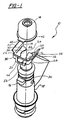
- FIG. 1 is an exploded perspective view of an assembly comprising a fuel injector, fuel rail cup and a spring clip constructed in accordance with the present invention.
-
- Referring now to the drawings in detail, a spring clip constructed in accordance with one embodiment of the present invention is generally indicated by
reference numeral 10 and is used for retaining together an associatedfuel injector 12 and afuel rail cup 14. As is hereinafter more fully described, thespring clip 10 provides improved retention of thefuel injector 12 in thefuel rail cup 14, fixing the injector against axial and rotational movement relative to the fuel rail cup. - As illustrated in Fig. 1,
clip 10 includes first and second parallel spacedside walls injector 12 and are disposed on diametrically opposite sides of the injector. Athird side wall 20, resiliently connects the first andsecond side walls injector 12. The first, second andthird walls third side wall 20 and that allows theside walls clip 10 to spring outward to be received over theinjector 12 and thefuel rail cup 14 when assembled. - The first and second parallel spaced
side walls flanges lower edges flanges inner edges fuel injector 12 to locate the injector axially relative to theclip 10.Herein edges - The first and second parallel spaced
side walls slots portion 42 of thefuel rail cup 14.Slots locate clip 10 axially relative to thecup 14, thereby locating thefuel injector 12 axially relative to the cup. Thethird side wall 20 includes anaperture 44 for receiving both a radially protruding orientation key orinjector key 46 of thefuel injector 12 and acorresponding orientation key 48 of thefuel rail cup 14.Aperture 44 is illustrated as being generally rectangular in shape although other shaped apertures can also be used. Theorientation keys injector 12 in thefuel rail cup 14. - Preferably, the
side walls clip 10 include angledupper portions aperture 44 is also angled outward with theupper portion 54 to assist the assembly process. As illustrated, the cross sectional shape of theprotruding orientation keys aperture 44 for mating relationship. Theclip 10 may be made of plastic or metal material provided the material has sufficient resiliency to maintain its U-shape. - Assembly of the
fuel injector 12 into thefuel rail cup 14 is accomplished by axially advancing theinlet end 56 of the injector into the fuel rail cup until thecorresponding orientation keys - In a preferred method of assembly, the
spring clip 10 is first mounted on theinjector 12 by advancing theopen side 22 radially so thatflanges arcuate edges injector key 46 extending intoaperture 44, and the angledupper portions injector inlet end 56. Theinjector 12 is then assembled with thefuel rail cup 14 as above described during which theangled portions sides side walls flange 42 of thecup 14 until the flange is received in theslots key 48 formed on the cup flange is moved axially into theaperture 44 in theclip side wall 20. This is possible because the upper part of theaperture 44 is angled outward withangled portion 54 ofside wall 20 so thekey 48 can slide axially into the aperture. Then upon engagement of theflange 42 withslots injector 12 to thecup 14, preventing further axial or rotational motion. - Alternatively, if desired, the
clip 10 may be installed after assembly of theinjector 12 to thecup 14. In this method, theopen side 22 ofclip 10 is advanced radially toward the injector/clip assembly.Flanges clip 10 spreads the flanges apart to allow them to pass onto the injector. As theclip 10 is being advanced radially toward theinjector 12,slots flanged portion 42 of thefuel rail cup 14. At the same time,aperture 44 receives protrudingorientation keys clip 10 is advanced further it snaps onto the assembly to fix theinjector 12 against axial and rotational movement relative to thefuel rail cup 14. - Although the invention has been described by reference to a specific embodiment, it should be understood that numerous changes may be made within the scope of the inventive concepts described. Accordingly, it is intended that the invention not be limited to the described embodiment, but that it have the full scope defined by the following claims.
Claims (7)
- A spring clip for retaining together a fuel injector (12) and a fuel rail cup (14), said clip comprising:first and second parallel spaced side walls (16;18); anda third side wall (20) resiliently connecting said first and second side walls to form a generally U-shaped body with an open side;said first and second parallel spaced side walls (16; 18) including flanges (24; 26) extending inwardly toward one another from opposed lower edges of said side walls, said flanges being configured to coact with an exterior surface of an associated fuel injector to locate said injector axially relative to said clip;said first and second parallel spaced side walls also including slots (38,40) arranged to receive a flanged portion (42) of said fuel rail cup such that said clip is located axially relative to said cup, thereby locating said injector axially relative to said cup; characterised in thatsaid third side wall (20) includs an aperture (44) for receiving both a radially protruding orientation key (46) of said injector and a corresponding orientation key (48) of said fuel rail cup;whereby when said injector and said clip are assembled with said fuel rail cup, said clip is effective to fix said injector against axial and rotational movement relative to said fuel rail cup.
- A spring clip as in claim 1 wherein said flanges include generally arcuate inner edges configured to coact with an associated circumferential groove in the fuel injector exterior surface.
- A spring clip as in claim 1 wherein said slots are disposed parallel with each other and transverse to the axis of the injector.
- A spring clip as in claim 1 wherein said aperture is generally rectangular in shape for receiving said orientation keys in mating relationship.
- A spring clip as in claim 1 wherein said side walls have outwardly angled upper portions that allow the clip to be preinstalled on an injector and to snap onto the cup flange when the injector inlet end is inserted into the cup.
- A spring clip as in claim 5 wherein said aperture extends into the angled upper portion of the third side wall, thereby forming a radial extension of the aperture that allows axial entry of the orientation key of said cup into said aperture.
- A spring clip as in claim 1 wherein, after preassembly of said injector into said fuel rail cup, said clip may be snapped onto the assembly to retain the injector against movement in the cup.
Applications Claiming Priority (2)
| Application Number | Priority Date | Filing Date | Title |
|---|---|---|---|
| US08/884,370 US5803052A (en) | 1997-06-27 | 1997-06-27 | Spring clip for retaining a fuel injector in a fuel rail cup |
| US884370 | 1997-06-27 |
Publications (3)
| Publication Number | Publication Date |
|---|---|
| EP0887543A2 EP0887543A2 (en) | 1998-12-30 |
| EP0887543A3 EP0887543A3 (en) | 2001-11-21 |
| EP0887543B1 true EP0887543B1 (en) | 2003-08-20 |
Family
ID=25384469
Family Applications (1)
| Application Number | Title | Priority Date | Filing Date |
|---|---|---|---|
| EP98110989A Expired - Lifetime EP0887543B1 (en) | 1997-06-27 | 1998-06-16 | Spring clip for retaining a fuel injector in a fuel rail cup |
Country Status (3)
| Country | Link |
|---|---|
| US (1) | US5803052A (en) |
| EP (1) | EP0887543B1 (en) |
| DE (1) | DE69817266T2 (en) |
Families Citing this family (53)
| Publication number | Priority date | Publication date | Assignee | Title |
|---|---|---|---|---|
| JPH10288125A (en) * | 1997-04-15 | 1998-10-27 | Sanou Kogyo Kk | Connector for fuel injection nozzle and its manufacture |
| US6053149A (en) * | 1998-05-28 | 2000-04-25 | Siemens Automotive Corporation | Fuel injector clip retention arrangement |
| US6003790A (en) * | 1998-10-14 | 1999-12-21 | Ford Global Technologies, Inc. | Pre-load mechanism having self-mounting coil spring |
| US5970953A (en) * | 1999-01-12 | 1999-10-26 | Siemens Automotive Corporation | High pressure injector clip |
| US6874477B1 (en) * | 1999-04-20 | 2005-04-05 | Siemens Vdo Automotive Corp. | Fuel injector mounting arrangement |
| US6264112B1 (en) * | 1999-05-26 | 2001-07-24 | Delphi Technologies, Inc. | Engine fuel injector |
| US6325049B1 (en) | 1999-06-23 | 2001-12-04 | Siemens Automotive Corporation | Fuel injector with orientation feature for orienting injector with respect to the manifold or head |
| JP3828701B2 (en) * | 1999-12-29 | 2006-10-04 | 株式会社ケーヒン | Mounting structure of fuel injection valve to fuel distribution pipe |
| US6250290B1 (en) | 2000-04-06 | 2001-06-26 | Transportation Design & Manufacturing Co. | Cooled LPG fuel rail |
| US6276339B1 (en) * | 2000-05-02 | 2001-08-21 | Delphi Technologies, Inc. | Fuel injector spring clip assembly |
| US6457456B1 (en) * | 2000-07-28 | 2002-10-01 | Siemens Automotive Corporation | Clip for injector to fuel supply assembly |
| US6382187B1 (en) * | 2000-08-07 | 2002-05-07 | Siemens Automotive Corporation | Clip for attachment of fuel supply assembly |
| US6418912B1 (en) | 2000-12-18 | 2002-07-16 | Siemens Automotive Corporation | HPDI injector and packaging |
| JP4325829B2 (en) * | 2001-03-08 | 2009-09-02 | 本田技研工業株式会社 | Fuel piping structure of fuel injection engine |
| DE10213585A1 (en) * | 2001-03-27 | 2002-10-02 | Denso Corp | Fuel supply device with an anti-slip element |
| LU90777B1 (en) | 2001-05-16 | 2002-11-18 | Delphi Tech Inc | Fuel injector assembly |
| DE10152421A1 (en) * | 2001-10-24 | 2003-06-18 | Bosch Gmbh Robert | fastening device |
| DE10163030B4 (en) * | 2001-12-20 | 2014-10-09 | Robert Bosch Gmbh | fastening device |
| JP3914488B2 (en) * | 2002-05-29 | 2007-05-16 | 株式会社オチアイ | Piping connection bracket |
| JP3922547B2 (en) * | 2002-06-28 | 2007-05-30 | 株式会社デンソー | Fuel supply apparatus and assembly method thereof |
| US6668803B1 (en) * | 2002-12-03 | 2003-12-30 | Ford Global Technologies, Llc | Fuel injector retention arrangement |
| DE10256668A1 (en) * | 2002-12-04 | 2004-07-29 | Robert Bosch Gmbh | support element |
| DE10359299A1 (en) * | 2003-12-17 | 2005-08-25 | Robert Bosch Gmbh | support element |
| US6830037B1 (en) * | 2004-01-27 | 2004-12-14 | Delphi Technologies, Inc. | Anti-rotation fuel injector clip |
| EP1721074A1 (en) * | 2004-02-26 | 2006-11-15 | Robert Bosch Gmbh | Support element |
| DE102004048401A1 (en) * | 2004-10-01 | 2006-04-06 | Robert Bosch Gmbh | Downholder for a fuel injector and fuel injector |
| US7360524B2 (en) * | 2004-12-03 | 2008-04-22 | Millenium Industries, Inc. | Fuel injector retention clip |
| US7159570B2 (en) * | 2004-12-03 | 2007-01-09 | Millennium Industries Corp. | Fuel injector retention clip |
| EP1703121A1 (en) * | 2005-02-24 | 2006-09-20 | Siemens VDO Automotive S.p.A. | Clip and fuel injector assembly |
| DE102006018194B4 (en) * | 2006-04-19 | 2010-06-10 | Winkelmann Powertrain Components Gmbh & Co. Kg | Device for fastening an injection valve in a valve seat of an internal combustion engine |
| FR2924765A3 (en) * | 2007-12-11 | 2009-06-12 | Renault Sas | Fuel injector for internal combustion engine, has cylindrical wall extending around male end and comprising axial maintaining element i.e. elastic ring, for maintaining injector on female end i.e. bush, of fuel injection rail |
| US7556022B1 (en) | 2008-01-04 | 2009-07-07 | Millennium Industries | Attachment for fuel injectors in direct injection fuel systems |
| EP2246555B1 (en) * | 2009-04-20 | 2012-07-18 | Continental Automotive GmbH | Coupling device and fuel injection arrangement |
| US7856962B2 (en) * | 2009-06-02 | 2010-12-28 | Hitachi Automotive Products (Usa), Inc. | Fuel system for a direct injection internal combustion engine |
| US8479710B2 (en) * | 2010-05-07 | 2013-07-09 | Continental Automotive Systems Us, Inc. | Injector to fuel rail coupling structure for high pressure direct injection engines |
| EP2388469B1 (en) | 2010-05-18 | 2013-03-13 | Continental Automotive GmbH | Fuel cup |
| DE102010017725B4 (en) * | 2010-07-05 | 2018-05-30 | Dr. Ing. H.C. F. Porsche Aktiengesellschaft | Injection arrangement for an internal combustion engine of a motor vehicle |
| JP5822271B2 (en) * | 2012-02-27 | 2015-11-24 | 株式会社ケーヒン | Support structure for fuel injection valve |
| JP5822272B2 (en) * | 2012-02-27 | 2015-11-24 | 株式会社ケーヒン | Support structure for fuel injection valve |
| US8701632B2 (en) * | 2012-07-24 | 2014-04-22 | Ford Global Technologies, Llc | Fuel injector mount |
| DE102013200751A1 (en) * | 2013-01-18 | 2014-07-24 | Robert Bosch Gmbh | Fuel injection system with a fuel-carrying component, a fuel injection valve and a connecting element |
| EP2824312B1 (en) | 2013-07-10 | 2017-06-28 | Continental Automotive GmbH | Fuel injection assembly for a combustion engine |
| EP2832986B1 (en) * | 2013-07-31 | 2016-05-25 | Continental Automotive GmbH | Fluid injection assembly for a combustion engine |
| EP2860388B1 (en) | 2013-10-10 | 2017-07-26 | Continental Automotive GmbH | Fluid injection assembly for a combustion engine |
| JP6274524B2 (en) * | 2014-06-30 | 2018-02-07 | ダイハツ工業株式会社 | Fuel supply device assembly method and clip |
| JP6256918B2 (en) * | 2014-09-30 | 2018-01-10 | 本田技研工業株式会社 | Injector assembly |
| JP6347485B2 (en) * | 2014-10-14 | 2018-06-27 | ダイハツ工業株式会社 | Injector unit for internal combustion engine |
| EP3279464B1 (en) * | 2016-08-04 | 2023-07-12 | Vitesco Technologies GmbH | A fuel injection assembly for an internal combustion engine |
| EP3279463A1 (en) * | 2016-08-04 | 2018-02-07 | Continental Automotive GmbH | A fuel injection assembly for an internal combustion engine |
| KR101938481B1 (en) * | 2017-06-23 | 2019-01-14 | 주식회사 현대케피코 | Clip for injector |
| KR20190001367A (en) * | 2017-06-27 | 2019-01-04 | 주식회사 현대케피코 | Injector fixing structure of fuel rail |
| CN108488017A (en) * | 2018-05-24 | 2018-09-04 | 海盐海博特机械有限公司 | A kind of atomizer tube body easy to use |
| US11136953B2 (en) * | 2018-11-20 | 2021-10-05 | Delphi Technologies Ip Limited | Fuel injector with a locating pin, internal combustion engine using the same, and method |
Family Cites Families (13)
| Publication number | Priority date | Publication date | Assignee | Title |
|---|---|---|---|---|
| DE3428597C2 (en) * | 1984-08-02 | 1986-11-27 | Bayerische Motoren Werke AG, 8000 München | Connection of two pipe sections arranged coaxially one behind the other, in particular an injection nozzle, with the coaxially arranged connection piece of an injection line |
| US4993390A (en) * | 1988-05-27 | 1991-02-19 | Mitsubishi Jidosha Kogyo Akbushiki Kaisha | Injector positioning device |
| DE3918410A1 (en) * | 1989-06-06 | 1990-12-13 | Bosch Gmbh Robert | FUEL INJECTION DEVICE FOR INTERNAL COMBUSTION ENGINES |
| GB8926363D0 (en) * | 1989-11-22 | 1990-01-10 | Lucas Ind Plc | Fuel injection system |
| DE4017875C2 (en) * | 1990-06-02 | 1999-02-04 | Bosch Gmbh Robert | Fuel injection device for internal combustion engines |
| US5211149A (en) * | 1990-06-29 | 1993-05-18 | Siemens Automotive L.P. | Fuel rail for bottom and side fed injectors |
| US5035224A (en) * | 1990-07-06 | 1991-07-30 | Siemens Automotive L.P. | Clip retention of a split-stream fuel injector to a fuel rail cup including circumferential locator |
| JP2591812Y2 (en) * | 1992-04-16 | 1999-03-10 | 住友電装株式会社 | Non-rotating connector |
| DE4413914A1 (en) * | 1994-04-21 | 1995-10-26 | Bosch Gmbh Robert | Fuel injector |
| US5501195A (en) * | 1994-09-16 | 1996-03-26 | Siemens Automotive Corporation | Retainer arrangement for a bottom feed fuel injector |
| DE19536441A1 (en) * | 1995-09-29 | 1997-04-03 | Saab Automobile | Spring clamp to connect injection nozzle to injection line |
| US5598824A (en) * | 1996-04-15 | 1997-02-04 | Ford Motor Company | Fuel delivery system for an internal combustion engine |
| JPH09291866A (en) * | 1996-04-30 | 1997-11-11 | Nissan Motor Co Ltd | Injector fixing device of engine |
-
1997
- 1997-06-27 US US08/884,370 patent/US5803052A/en not_active Expired - Lifetime
-
1998
- 1998-06-16 EP EP98110989A patent/EP0887543B1/en not_active Expired - Lifetime
- 1998-06-16 DE DE69817266T patent/DE69817266T2/en not_active Expired - Lifetime
Also Published As
| Publication number | Publication date |
|---|---|
| EP0887543A3 (en) | 2001-11-21 |
| DE69817266T2 (en) | 2004-08-05 |
| DE69817266D1 (en) | 2003-09-25 |
| US5803052A (en) | 1998-09-08 |
| EP0887543A2 (en) | 1998-12-30 |
Similar Documents
| Publication | Publication Date | Title |
|---|---|---|
| EP0887543B1 (en) | Spring clip for retaining a fuel injector in a fuel rail cup | |
| US6668803B1 (en) | Fuel injector retention arrangement | |
| JP3535460B2 (en) | Fuel injector clip holding mechanism | |
| US5967674A (en) | Selective washer and thrust bearing assembly | |
| US5167213A (en) | Fuel injection device for internal combustion engines | |
| US4861208A (en) | Door trim panel fastening assembly | |
| US7017239B2 (en) | Component connection system | |
| US7549199B2 (en) | Device for connecting a carrier part and an add-on piece | |
| US5724946A (en) | Fuel rail and injector assembly | |
| US6830037B1 (en) | Anti-rotation fuel injector clip | |
| US7088297B2 (en) | Vehicle roof antenna attachment | |
| KR0159096B1 (en) | Fuel injection device for internal combustion engines | |
| US8261706B2 (en) | Timing adjustment device for an internal combustion engine | |
| US5005878A (en) | Coupler element | |
| EP0589972A1 (en) | Means for mounting a fuel injector on a fuel rail | |
| US7703813B1 (en) | Electrical connector with snap fit retaining ring with improved holding and grounding tangs | |
| JP2002340210A (en) | Device for installing actuator or thermostat head on valve | |
| JPH03182845A (en) | Device for mounting angle regulating head to reflector for head light for automobile and assembly thereof | |
| EP0101940A1 (en) | Attaching post for snap fastener elements | |
| KR20020029085A (en) | Reduced cost bearing retainer | |
| US20220042637A1 (en) | Device For Connecting Two Tubular Objects | |
| GB2307508A (en) | One-piece fastener | |
| US7445253B2 (en) | Clamp for fastening and connecting tubes | |
| JPH1022047A (en) | Spark plug-boot assembly | |
| US6086021A (en) | Adjustable anti-rotational fastener for wire harness components |
Legal Events
| Date | Code | Title | Description |
|---|---|---|---|
| PUAI | Public reference made under article 153(3) epc to a published international application that has entered the european phase |
Free format text: ORIGINAL CODE: 0009012 |
|
| AK | Designated contracting states |
Kind code of ref document: A2 Designated state(s): AT BE CH CY DE DK ES FI FR GB GR IE IT LI LU MC NL PT SE Kind code of ref document: A2 Designated state(s): DE FR GB IT |
|
| AX | Request for extension of the european patent |
Free format text: AL;LT;LV;MK;RO;SI |
|
| 17P | Request for examination filed |
Effective date: 19990420 |
|
| PUAL | Search report despatched |
Free format text: ORIGINAL CODE: 0009013 |
|
| AK | Designated contracting states |
Kind code of ref document: A3 Designated state(s): AT BE CH CY DE DK ES FI FR GB GR IE IT LI LU MC NL PT SE |
|
| AX | Request for extension of the european patent |
Free format text: AL;LT;LV;MK;RO;SI |
|
| AKX | Designation fees paid |
Free format text: DE FR GB IT |
|
| GRAH | Despatch of communication of intention to grant a patent |
Free format text: ORIGINAL CODE: EPIDOS IGRA |
|
| GRAH | Despatch of communication of intention to grant a patent |
Free format text: ORIGINAL CODE: EPIDOS IGRA |
|
| GRAA | (expected) grant |
Free format text: ORIGINAL CODE: 0009210 |
|
| AK | Designated contracting states |
Designated state(s): DE FR GB IT |
|
| REG | Reference to a national code |
Ref country code: GB Ref legal event code: FG4D |
|
| REF | Corresponds to: |
Ref document number: 69817266 Country of ref document: DE Date of ref document: 20030925 Kind code of ref document: P |
|
| PGFP | Annual fee paid to national office [announced via postgrant information from national office to epo] |
Ref country code: GB Payment date: 20040604 Year of fee payment: 7 |
|
| ET | Fr: translation filed | ||
| PLBE | No opposition filed within time limit |
Free format text: ORIGINAL CODE: 0009261 |
|
| STAA | Information on the status of an ep patent application or granted ep patent |
Free format text: STATUS: NO OPPOSITION FILED WITHIN TIME LIMIT |
|
| 26N | No opposition filed |
Effective date: 20040524 |
|
| PG25 | Lapsed in a contracting state [announced via postgrant information from national office to epo] |
Ref country code: IT Free format text: LAPSE BECAUSE OF NON-PAYMENT OF DUE FEES;WARNING: LAPSES OF ITALIAN PATENTS WITH EFFECTIVE DATE BEFORE 2007 MAY HAVE OCCURRED AT ANY TIME BEFORE 2007. THE CORRECT EFFECTIVE DATE MAY BE DIFFERENT FROM THE ONE RECORDED. Effective date: 20050616 Ref country code: GB Free format text: LAPSE BECAUSE OF NON-PAYMENT OF DUE FEES Effective date: 20050616 |
|
| GBPC | Gb: european patent ceased through non-payment of renewal fee |
Effective date: 20050616 |
|
| PGFP | Annual fee paid to national office [announced via postgrant information from national office to epo] |
Ref country code: FR Payment date: 20060623 Year of fee payment: 9 |
|
| REG | Reference to a national code |
Ref country code: FR Ref legal event code: ST Effective date: 20080229 |
|
| PG25 | Lapsed in a contracting state [announced via postgrant information from national office to epo] |
Ref country code: FR Free format text: LAPSE BECAUSE OF NON-PAYMENT OF DUE FEES Effective date: 20070702 |
|
| PGFP | Annual fee paid to national office [announced via postgrant information from national office to epo] |
Ref country code: DE Payment date: 20150630 Year of fee payment: 18 |
|
| REG | Reference to a national code |
Ref country code: DE Ref legal event code: R119 Ref document number: 69817266 Country of ref document: DE |
|
| PG25 | Lapsed in a contracting state [announced via postgrant information from national office to epo] |
Ref country code: DE Free format text: LAPSE BECAUSE OF NON-PAYMENT OF DUE FEES Effective date: 20170103 |