EP0887530A2 - Gas turbine with exhaust gas recirculation - Google Patents
Gas turbine with exhaust gas recirculation Download PDFInfo
- Publication number
- EP0887530A2 EP0887530A2 EP98111886A EP98111886A EP0887530A2 EP 0887530 A2 EP0887530 A2 EP 0887530A2 EP 98111886 A EP98111886 A EP 98111886A EP 98111886 A EP98111886 A EP 98111886A EP 0887530 A2 EP0887530 A2 EP 0887530A2
- Authority
- EP
- European Patent Office
- Prior art keywords
- compressor
- gas turbine
- exhaust gas
- gas
- recirculation
- Prior art date
- Legal status (The legal status is an assumption and is not a legal conclusion. Google has not performed a legal analysis and makes no representation as to the accuracy of the status listed.)
- Withdrawn
Links
Images


Classifications
-
- F—MECHANICAL ENGINEERING; LIGHTING; HEATING; WEAPONS; BLASTING
- F02—COMBUSTION ENGINES; HOT-GAS OR COMBUSTION-PRODUCT ENGINE PLANTS
- F02C—GAS-TURBINE PLANTS; AIR INTAKES FOR JET-PROPULSION PLANTS; CONTROLLING FUEL SUPPLY IN AIR-BREATHING JET-PROPULSION PLANTS
- F02C3/00—Gas-turbine plants characterised by the use of combustion products as the working fluid
- F02C3/34—Gas-turbine plants characterised by the use of combustion products as the working fluid with recycling of part of the working fluid, i.e. semi-closed cycles with combustion products in the closed part of the cycle
-
- F—MECHANICAL ENGINEERING; LIGHTING; HEATING; WEAPONS; BLASTING
- F01—MACHINES OR ENGINES IN GENERAL; ENGINE PLANTS IN GENERAL; STEAM ENGINES
- F01D—NON-POSITIVE DISPLACEMENT MACHINES OR ENGINES, e.g. STEAM TURBINES
- F01D13/00—Combinations of two or more machines or engines
-
- F—MECHANICAL ENGINEERING; LIGHTING; HEATING; WEAPONS; BLASTING
- F02—COMBUSTION ENGINES; HOT-GAS OR COMBUSTION-PRODUCT ENGINE PLANTS
- F02C—GAS-TURBINE PLANTS; AIR INTAKES FOR JET-PROPULSION PLANTS; CONTROLLING FUEL SUPPLY IN AIR-BREATHING JET-PROPULSION PLANTS
- F02C3/00—Gas-turbine plants characterised by the use of combustion products as the working fluid
- F02C3/20—Gas-turbine plants characterised by the use of combustion products as the working fluid using a special fuel, oxidant, or dilution fluid to generate the combustion products
- F02C3/30—Adding water, steam or other fluids for influencing combustion, e.g. to obtain cleaner exhaust gases
- F02C3/305—Increasing the power, speed, torque or efficiency of a gas turbine or the thrust of a turbojet engine by injecting or adding water, steam or other fluids
-
- F—MECHANICAL ENGINEERING; LIGHTING; HEATING; WEAPONS; BLASTING
- F02—COMBUSTION ENGINES; HOT-GAS OR COMBUSTION-PRODUCT ENGINE PLANTS
- F02C—GAS-TURBINE PLANTS; AIR INTAKES FOR JET-PROPULSION PLANTS; CONTROLLING FUEL SUPPLY IN AIR-BREATHING JET-PROPULSION PLANTS
- F02C6/00—Plural gas-turbine plants; Combinations of gas-turbine plants with other apparatus; Adaptations of gas- turbine plants for special use
- F02C6/18—Plural gas-turbine plants; Combinations of gas-turbine plants with other apparatus; Adaptations of gas- turbine plants for special use using the waste heat of gas-turbine plants outside the plants themselves, e.g. gas-turbine power heat plants
-
- F—MECHANICAL ENGINEERING; LIGHTING; HEATING; WEAPONS; BLASTING
- F02—COMBUSTION ENGINES; HOT-GAS OR COMBUSTION-PRODUCT ENGINE PLANTS
- F02C—GAS-TURBINE PLANTS; AIR INTAKES FOR JET-PROPULSION PLANTS; CONTROLLING FUEL SUPPLY IN AIR-BREATHING JET-PROPULSION PLANTS
- F02C7/00—Features, components parts, details or accessories, not provided for in, or of interest apart form groups F02C1/00 - F02C6/00; Air intakes for jet-propulsion plants
- F02C7/08—Heating air supply before combustion, e.g. by exhaust gases
-
- F—MECHANICAL ENGINEERING; LIGHTING; HEATING; WEAPONS; BLASTING
- F02—COMBUSTION ENGINES; HOT-GAS OR COMBUSTION-PRODUCT ENGINE PLANTS
- F02C—GAS-TURBINE PLANTS; AIR INTAKES FOR JET-PROPULSION PLANTS; CONTROLLING FUEL SUPPLY IN AIR-BREATHING JET-PROPULSION PLANTS
- F02C9/00—Controlling gas-turbine plants; Controlling fuel supply in air- breathing jet-propulsion plants
- F02C9/16—Control of working fluid flow
- F02C9/18—Control of working fluid flow by bleeding, bypassing or acting on variable working fluid interconnections between turbines or compressors or their stages
-
- Y—GENERAL TAGGING OF NEW TECHNOLOGICAL DEVELOPMENTS; GENERAL TAGGING OF CROSS-SECTIONAL TECHNOLOGIES SPANNING OVER SEVERAL SECTIONS OF THE IPC; TECHNICAL SUBJECTS COVERED BY FORMER USPC CROSS-REFERENCE ART COLLECTIONS [XRACs] AND DIGESTS
- Y02—TECHNOLOGIES OR APPLICATIONS FOR MITIGATION OR ADAPTATION AGAINST CLIMATE CHANGE
- Y02E—REDUCTION OF GREENHOUSE GAS [GHG] EMISSIONS, RELATED TO ENERGY GENERATION, TRANSMISSION OR DISTRIBUTION
- Y02E20/00—Combustion technologies with mitigation potential
- Y02E20/16—Combined cycle power plant [CCPP], or combined cycle gas turbine [CCGT]
Definitions
- This invention relates to a gas turbine apparatus, and more particularly to a exhaust gas recirculating type combined cycle plant wherein exhaust gas is recirculated to an air intake side of a compressor.
- Japanese Unexamined Patent Application No.Hei7-34900 has disclosed an exhaust gas recirculating type combined plant wherein a part of exhaust gas from a gas turbine is returned to an air intake of a compressor so as to raise a compressor air intake temperature so that a combustion temperature at the time of partial loading or gas turbine exhaust gas temperature is prevented from dropping thereby preventing a drop in cycle heat efficiency at the time of the partial loading.
- Japanese Unexamined Patent Application No.Hei7-34900 has not disclosed anything about widening a range in which high efficiency partial load operation is enabled by stabilized recirculation of exhaust gas. Further, Japanese Unexamined Patent Application No.Sho56-141040 has not mentioned anything about the partial load operation.
- the combined cycle plant has such a feature that there exists an atmospheric temperature maximizing its plant efficiency and the plant efficiency drops at other temperatures than the atmospheric temperature.
- An object of the present invention is to provide an exhaust gas recirculation type gas turbine apparatus having a wide partial load operation range allowing high efficiency operation.
- Another object of the present invention is to provide an exhaust gas recirculation type gas turbine apparatus capable of obtaining a desired output efficiently even when the external temperature changes.
- the first invention provides an exhaust gas recirculation type gas turbine apparatus comprising: a compressor for compressing air; a combustion chamber for burning compression air exhausted from the compressor and fuel; a gas turbine driven by gas turbine exhaust gas from the combustion chamber; a recirculation path for recirculating a part of the gas turbine exhaust gas to an intake of the compressor: a recirculation amount control unit for adjusting an amount of gas turbine exhaust gas to be returned to the intake of the compressor corresponding to a change in load of the gas turbine; and a spray unit for introducing liquid droplets into an interior of the compressor in which mixing gas comprising gas turbine exhaust gas passing through the recirculation path and air flows go as to vaporize the introduced liquid droplet during a flow in the compressor.
- the gas turbine exhaust gas recirculation type gas turbine apparatus comprises: a compressor for compressing air; a combustion chamber for burning compression air exhausted from the compressor and fuel; a gas turbine driven by gas turbine exhaust gas from the combustion chamber; a recirculation path for recirculating a part of the gas turbine exhaust gas to an intake of the compressor: a recirculation amount control unit for adjusting an amount of gas turbine exhaust gas to be returned to the intake of the compressor corresponding to a change in load of the gas turbine: and a spray unit for spraying liquid droplets over air supplied to the compressor and gas turbine exhaust gas passing through said recirculation path so as to introduce the liquid droplets into the compressor in which the air and the gas turbine exhaust gas flow so that the introduced liquid droplets are vaporized during a flow in said compressor.
- the temperature of the mixing gas entering the compressor can be raised, resulting in the increase of the recirculation amount. Further, the improvement of the heat efficiency in the compressor allows the partial load operation range allowing a high efficiency operation of the compressor to be widened.
- the second invention provides an exhaust gas recirculation type gas turbine apparatus comprising: a compressor for compressing air; a combustion chamber for burning compression air exhausted from the compressor and fuel; a gas turbine driven by gas turbine exhaust gas from the combustion chamber; a recirculation path for recirculating a part of the gas turbine exhaust gas to an intake of the compressor; a recirculation amount control unit for adjusting an amount of gas turbine exhaust gas to be returned to the intake of the compressor corresponding to a change in load of the gas turbine; a spray unit for introducing liquid droplets into an interior of the compressor in which mixing gas comprising gas turbine exhaust gas passing through the recirculation path and air flows so as to vaporize the introduced liquid droplet during a flow in said compressor; and a spray amount control unit for controlling a spray amount of the liquid droplets corresponding to the recirculation amount.
- the temperature of the mixing gas entering the compressor can be raised, resulting in the increase of the recirculation amount. Further, because the heat efficiency in the compressor can be improved, the partial load operation range allowing a high efficiency operation of the compressor can be widened.
- the compressor intake temperature and exit temperature change are depended on the recirculation amount, and thereby the spray amount can be appropriately adjusted.
- the third invention provides an exhaust gas recirculation type gas turbine apparatus comprising: a compressor for compressing air; a combustion chamber for burning compression air exhausted from the compressor and fuel; a gas turbine driven by gas turbine exhaust gas from the combustion chamber; a recirculation path for recirculating a part of the gas turbine exhaust gas to an intake of the compressor; a spray unit for introducing liquid droplets into an interior of the compressor in which mixing gas comprising gas turbine exhaust gas passing through the recirculation path and air flows so as to vaporize the introduced liquid droplet during a flow in the compressor; a temperature detector for detecting a temperature of air supplied to the compressor: and a control unit for controlling so that in the case of a first temperature region in which the detected temperature is set, the recirculation is executed and spray of droplets from the spray unit is stopped, in the case of a second temperature region which is higher than the first temperature region, the recirculation is executed and the spray of droplets from the spray unit is executed and in the case of a third temperature region which is higher than the second
- An exhaust gas recirculation type gas turbine apparatus is preferred to comprise a control unit for controlling a spray amount of droplet from said spray unit depending on a humidity of air supplied to the compressor.
- the fourth invention provides an exhaust gas recirculation type gas turbine apparatus comprising: a control unit for controlling so that in the case of a first temperature region in which the detected temperature is set, the recirculation is executed and spray of droplets from the spray unit is stopped, in the case of a second temperature region which is higher than the first temperature region, the recirculation is stopped and the spray of droplets from the spray unit is stopped and in the case of a third temperature region which is higher than the second temperature region, said recirculation is stopped and the spray of droplets from the spray unit is executed.
- An exhaust gas recirculation type gas turbine apparatus is preferred to comprise a control unit for controlling a spray amount of droplet from said spray unit depending on a humidity of air supplied to the compressor.
- An exhaust gas recirculation type gas turbine apparatus further comprising a control unit for controlling a spray amount of droplet from said spray unit depending on a humidity of air supplied to the compressor.
- an exhaust gas recirculation type gas turbine apparatus comprising: a compressor for compressing air; a gas turbine chamber for burning compression air exhausted from the compressor and fuel; a gas turbine driven by gas turbine exhaust gas from the gas turbine chamber; a recirculation path for recirculating a part of the gas turbine exhaust gas to an intake of the compressor; and a carbon dioxide gas removing unit installed in a flow path of gas turbine exhaust gas for reducing the concentration of carbon dioxide gas in the gas turbine exhaust gas discharged after air containing the recirculated exhaust gas is introduced to the gas turbine chamber.
- carbon dioxide e.g., CO 2
- the size of the carbon dioxide removing unit can be reduced. Because the pressure loss of the gas turbine exhaust path con be reduced by the miniaturization, the efficiency drop during the gas turbine operation can be suppressed thereby contributing to the high efficiency operation.
- the carbon dioxide gas removing measure can be disposed between a diverging portion of the recirculation path of the gas turbine exhaust gas path and an emitting portion for emitting the gas turbine exhaust gas.
- the gas turbine exhaust gas containing high concentration carbon dioxide gas can be removed, so that the carbon dioxide gas removing efficiency can be maintained at a high level in addition to the aforementioned effect. Further, because the pressure loss can be further reduced, the high efficiency operation is enhanced.
- the carbon dioxide gas removing measure can be disposed between the gas turbine of the gas turbine exhaust gas path and the diverging portion of the recirculation path. As a result, a large amount of the gas turbine exhaust gas can be supplied so that the carbon dioxide gas removing efficiency can be maintained at a high level in addition to the aforementioned effect.
- the carbon dioxide gas removing measure can be disposed on the recirculation path.
- the carbon dioxide gas removing unit can be installed easily. Further, the maintenance work for this unit is facilitated. Further, the pressure loss at a discharge portion of exhaust gas to the air can be reduced, the efficiency drop of the gas turbine can be further suppressed.
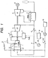
- FIG. 1 shows a first embodiment of the present invention.
- An exhaust gas recirculating type combined plant employing a gas turbine intake air water spraying system comprises: a compressor (compressor) 1 for sucking and compressing air, a combustion chamber 2 for mixing and burning the compressed air and fuel; a gas turbine 3 which is driven by combustion gas supplied from the combustion chamber 2; an exhaust heat recovery boiler 4 for recovering heat of the gas turbine exhaust gas from the gas turbine 3 so as to generate steam by heat exchange with supplied water: a steam turbine 5 which is driven by the steam generated by the gas turbine exhaust heat recovery boiler 4; a generator 6 coupled with the steam turbine 5; a recirculating means (pipe) 9 composing a reCirculating path for taking out part of the gas turbine exhaust gas of the gas turbine 3 and recirculating it up to a compressor intake; and a recirculation amount control means (exhaust gas recirculation amount adjusting valve) 10 for controlling the recirculation amount.
- each turbine may drive each generator.
- This combined plant further comprises a fuel amount control valve (fuel supply system) 7 for controlling an amount of fuel supplied to the combustion chamber 2 and an integrated control device 8 for controlling the fuel amount control valve 7 and the recirculation amount control means 10.
- a fuel amount control valve fuel supply system
- an integrated control device 8 for controlling the fuel amount control valve 7 and the recirculation amount control means 10.
- spray nozzles 11 for spraying fine droplets of liquid are disposed in a suction duct 21.
- a supply water amount adjusting valve 12 for controlling a spray amount, a water tank 13 for storing water and a water supply pump 14 are disposed on a path for supplying water to the spray nozzles. If the aforementioned nozzle requires an air supplying means for obtaining fine liquid droplets, an air flow adjusting valve 15 is disposed on a suction air supply path.
- Generation output of the aforementioned combined plant is operated by the fuel amount control valve 7 for controlling an amount of fuel loaded on the combustion chamber 2, recirculation amount control means 10, spray amount (supply water amount) adjusting valve 12, air flow adjusting valve 15 and determined by adjusting their opening degrees. These operation ends are controlled depending on an operation signal from the integrated control device 8.
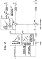
- the integrated control device 8 receives a load request signal Ld from a central power supply control room 16 for the combined plant and controls the entire plant so as to appropriately control air amount, fuel amount and spray amount.
- a deviation between a load request signal Ld and an actual load L is obtained by a subtractor AD1 and a fuel target signal Fd is obtained by an adjusting device PI1. Then, a deviation between the fuel target signal Fd and actual fuel amount F is obtained by a subtractor AD2 and then the fuel amount control valve 7 is adjusted by the adjusting device PI2 to determine an amount of fuel to be loaded on the combustion chamber. According to this control, the larger the load, the larger amount of fuel is supplied to the combustion chamber 2.
- the recirculation amount increases in terms of supplying speed, preventing a reduction of the combustion temperature or gas turbine exhaust gas temperature accompanied by a reduction of the load.
- the combustion temperature gas turbine exhaust gas temperature
- the function generator FG1 of Fig. 1 a recirculation rate of the gas turbine exhaust gas amount is determined corresponding to the load.
- the output signal S1 of the function generator FG1 can maintain the gas turbine exhaust gas temperature substantially constant regardless of the load.
- the gas turbine exhaust gas temperature can be maintained at a substantially constant level regardless of the load.
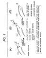
- liquid droplets to be vaporized in the compressor is introduced into the suction air in which the outside air of atmospheric temperature and high temperature gas turbine exhaust gas are mixed with each other.
- internal gas of the compressor is cooled so that the axial velocity A' is reduced at the rear end of the compressor. Consequently, the incidence ⁇ is also reduced so that the apparent velocity B becomes parallel to the vane thereby stabilizing the compressor characteristic.
- the compressor suction air temperature can be further increased. That is, because the gas turbine exhaust air recirculation amount can be increased more, the high efficiency partial load operation range can be expanded.
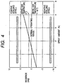
- Fig. 4 shows a change in incidence relative to the spray amount.
- the gas turbine is designed so as to be operated under an atmospheric temperature of 0°C-50°C.
- the characteristic of the compressor is stabilized regardless of the incidence being changed by a change in the compressor auction air temperature.
- the compressor suction air temperature exceeds this range, the absolute value of the incidence is increased, so the characteristic of the compressor becomes unstable.
- a positive stalling (stall) or a negative stalling (choke) may occur.
- the internal gas inside the compressor is cooled so as to improve the incidence.
- the incidence is at the lower limit of the regular operation range when the suction air temperature is 50°C
- the incidence is gradually restored, resulting in the incidence being restored to 0 deg with a spray amount of 1.5%. If the spray amount is increased, the problematic positive stalling (stall) requires an appropriate spray amount to be selected.
- introducing the liquid droplets to be vaporized in the compressor causes a temperature difference between the compressor intake gas and exit gas to be minimized.
- the intake temperature is substantially constant and the exit temperature drops or the reduction amount of the exit temperature is made larger than the reduction amount of the intake temperature.
- the recirculation amount can be increased with the compressor exit temperature being substantially constant.
- the recirculation can be attained even at the time of low partial load operation.
- the efficiency under the partial load can be improved as compared to the case of the aforementioned conventional art.
- the water droplets entering the compressor are vaporized and if the vaporization is completed, the gas in the compressor is subjected to adiabatic compression.
- the specific heat under a constant pressure of steam is about twice that of the mixing gas around a typical temperature (300°C) in the compressor and therefore, in terms of thermal capacity, if calculated on the basis of the mixing gas, the same effect is produced as when the mixing gas having a weight about twice that of water droplets to be vaporized acts as an operating liquid.
- a drop of the mixing gag temperature at the exit of the compressor has an effect (temperature rise inhibit effect).
- the vaporization of water droplets in the compressor like this causes the drop of the mixing gas temperature at the exit of the compressor.
- An operating power of the compressor is equal to a difference of mixing gas entropy between the intake and exit of the compressor and the mixing gas entropy is proportional to the temperature.
- the increased output attains a heat efficiency of 100%. Therefore, the heat efficiency of the gas turbine can be improved. Because the combustion temperature is maintained at a constant level, the heat efficiency of bottoming cycle is the same as before the present invention has been applied. Therefore, the heat efficiency of the combined cycle total can be improved.
- the intake air is cooled so that the weight flow rate of the intake air introduced into the compressor 1 is increased, resulting in the possibility of a increase of the load of the gas turbine to be driven under a low load.
- the diameter of the sprayed liquid droplet is large, it collides with the vane or casing of the compressor 1 so that it is vaporized by receiving a heat from the metal. As a result, the temperature reduction effect of the operating liquid may be obstructed. Thus, the diameter of the liquid droplet is desired to be as small as possible from this viewpoint.
- the sprayed liquid droplet has a distribution of the diameters of the droplets.
- the diameter of the sprayed liquid droplets is controlled so as to be 50 ⁇ m or below.
- the maximum diameter thereof is desired to be 50 ⁇ m or below.
- the Sautor average diameter (S.D.M) is 30 ⁇ m or below. Because the liquid droplets ejected from an injection nozzle has a distribution of grain size, the aforementioned maximum diameter is difficult to be measured. Thus, for actual use, the measurement of the aforementioned Sautor average diameter (S.D.M.) is applied. Although the diameter of the droplet is desired to be as small as possible, an injection nozzle for producing a small droplet requires a high precision production technology. Thus, a lower limit allowing technically as small a droplet as possible is an actual range of the aforementioned diameter thereof.
- the aforementioned main droplet diameter, maximum diameter and average diameter 1 ⁇ m is a lower limit.
- the smaller the diameter of the droplets the more energy is consumed for generating such droplets.
- the aforementioned lower limit considering the energy to be consumed for generation of the liquid droplets, it is permissible to determine the aforementioned lower limit. If the droplet size is a size allowing it to float in the atmosphere so that it is not likely to drop, generally, the condition of its contact surface is excellent.
- Sautor average diameter S.D.M.
- the lover limit technically allowing the droplet diameter to be reduced is the lower limit for the aforementioned grain size.
- such lower limit is 1 ⁇ m.
- An introduction amount of the droplets can be adjusted depending on the temperature, humidity and an increase of the output. Taking into account an amount of the vaporization of the liquid droplets in an interval from a spraying point to the compressor intake, more than 2 wt% relative to the intake air weight flow rate can be introduced. Its upper limit is determined in a range capable of maintaining the function of the compressor in an excellent condition. For example, it is possible to determine the upper limit to be 5 wt% such that the introduction range is below this value.
- the introduction range can be adjusted considering summer season and dry condition, to further increase the output, it is possible to introduce at 0.8 wt% or more and 5 wt% or below.
- reference numeral 22 denotes IGV.
- the spray nozzle is disposed at any position of 11a - 11d.
- the injection nozzle 11a is disposed via a predetermined distance from the compressor exit.
- a silencer is disposed within the suction duct 21, it is disposed in the downstream relative thereto.
- a part of the liquid droplet is vaporized before it is introduced into the compressor and after it is introduced into the compressor, it is further vaporized during a flow in the compressor.
- the spray nozzle 11b is disposed on an introduction vane provided in the most upstream which is an introduction portion of the compressor, provided at the compressor intake.
- An air supplying path and water supplying path are disposed within the same vane.
- a spray nozzle 11c is disposed between the aforementioned guide vane and IGV. This prevents the sprayed liquid droplets from being vaporized before entering the compressor and the weight flow rate of the mixing gas from increasing. From such a viewpoint, it is desirable to install the injection nozzle near the IGV.
- An injection nozzle 11d is disposed at the middle of the compressor.
- this injection nozzle may be installed at the middle stage of the compressor near the rear end.
- the nozzle is installed on a stationary vane as shown by an enlarged view and a water supplying means and air supplying means are provided within the vane.
- the sprayed liquid droplets flowing in the compressor move between the vanes of the compressor along its flow line.
- the intake air is heated by adiabatic compression, so that the liquid droplets are vaporized from the surface by this heat and while the diameter thereof is being reduced, transferred to the rear end vane.
- vaporization latent heat required for vaporization lowers the temperature of the mixing gas in the compressor because it depends on the mixing gas in the compressor.
- the spray amount of the aforementioned injection nozzle 11 is controlled so as to correspond to a recirculating amount of the combustion gas. For example, it is controlled so that the spray amount is larger when the recirculating amount is large than when the recirculating amount is small.
- the mixing gas composed of the gas turbine exhaust gas through the recirculating pipe 9 and air supplied through the suction duct 21 is introduced to the compressor 1 and in the compressor 1, the aforementioned mixing gas is compressed and discharged.
- the aforementioned fine liquid droplets are sprayed from the aforementioned spray nozzle 11 and introduced into the compressor, and during a flow in the compressor 1, the liquid droplets are vaporized.
- the partial load operation range in which a high efficiency operation is enabled by recirculating the gas turbine exhaust gas can be enlarged as compared to carrying out only the gas turbine exhaust gas recirculation.
- This signal is input to the function generator FG3 in which a spray amount increases as a recirculation amount increases.
- An output signal S2 of water droplet spray amount relative to the recirculation amount is obtained.
- This signal S2 and a next gas temperature of the compressor actually measured are applied to a subtractor AD14 and then a correction spray amount signal of the function generator FG3 is output.
- This signal is supplied to an adjustor P14 to control a spray amount (supply water amount) adjusting valve 12.
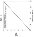
- Fig. 5 indicates a control line of the spray rate relative to the recirculation rate assuming that the gas turbine exhaust temperature is constant. The spray rate increases substantially linearly relative to the recirculation rate.
- the incidence of the vane in the compressor is changed by the recirculating operation as described before, it can be returned to a state before exhaust gas recirculation by control of the aforementioned control line.
- the spray amount on outside air weight basis
- the spray amount is about 5.5%.
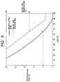
- Fig. 9 indicates a relation between mixing gas intake temperature and recirculation rate relative to each load.
- the mixing gas (volumetric flow rate) sucked into the compressor 1 is constant regardless of the load because the gas turbine 3 is rotating at a constant speed.
- the gas turbine exhaust gas recirculation amount increases, so that correspondingly the compressor intake air temperature rises.
- the gas turbine output drops owing to the decrease of the compressor intake suction weight flow rate.
- the upper limit of the compressor intake air is 50°C and therefore the recirculation amount is restricted so that the gas turbine output reduction is also restricted.
- spraying fine liquid droplets at the compressor intake so as to cool the compressor internal gas liquid behavior in the vicinity of the compressor vane is improved.
- the gas turbine exhaust gas recirculation amount can be increased so that operation at a lower load is enabled and further a higher efficiency partial load operation is enabled.
- the combustion temperature can be maintained at a constant level by increasing a fuel loading amount.
- the combustion gas works in a process of its adiabatic expansion in the gas turbine 3. Because a part of the combustion gas is consumed for driving the compressor 1 and generator 6, net output thereof corresponds to that difference.
- the part of the gas turbine exhaust gas from the gas turbine 3 recirculates through the recirculating means 9 and control means (exhaust gas recirculation amount adjusting valve) 10 as a part of the intake air in the compressor 1.
- control means exhaust gas recirculation amount adjusting valve
- high pressure steam is generated and this steam drives the steam turbine 5 and generator 6 to generate power.
- Fig. 10 shows a comparison of efficiency drop due to respective loads in the combined cycle with efficiency drop in ordinary combined cycle, exhaust gas recirculation type combined cycle and the present embodiment.
- efficiency drop in a range up to 90% load in which combustion temperature constant operation is carried out is not so large, the combustion temperature drops at an operation having a less than 90% load. Therefore the efficiency drops rapidly, so that at the 25% load which is a load determined by a restriction on the bottoming side, the efficiency drops in terms of a relative value by about 40%.
- the combustion temperature constant operation by the aforementioned IGV or the like has a range slightly different depending on machine. However, in most cases, the efficiency drop is up to 80% even if it is small.
- a lower limit is preferred to be determined depending on setting of the apparatus, and generally, it is considered that in most cases, the recirculation is carried out up to at least 50% load.
- Fig. 10 considers operation by control by IGV or the like in a range in which combined cycle load is 100-90% or 80%, the present invention is not restricted to this example, it is permissible to control the recirculation amount correspondingly if the load descends from 100%.
- the compressor intake temperature is 150°C when the combined cycle load is 74%, 112°C when 50% and 240°C when 30%.
- the compressor exit temperature by reducing the compressor exit temperature by introducing liquid droplets to be vaporized in the compressor, inconveniences which may occur at the rear end of the compressor can be avoided.
- the recirculation rate by controlling the spray amount of the liquid droplets to be vaporized in the compressor, it is possible to control so that the temperature of the mixing gas at the compressor intake rises.
- the recirculation amount can be increased as compared to a plain recirculation plant, so that the recirculation amount can be increased even in low partial load operation range.
- a combined plant load range of at least 50-80% it is possible to control so that the aforementioned spray amount is increased as the recirculation amount is increased and that the recirculation amount is continuously increased as the load is decreased.
- the aforementioned recirculation amount corresponding to the load so as to suppress a deflection of the combustion temperature in the combustion chamber in a combined plant load range of at least 50%-80% (for example, controlling so that the recirculation amount is increased as the load is decreased) and introducing the liquid droplets into the compressor, it is possible to suppress a temperature rise of the compression air at the compressor exit.
- the aforementioned recirculation amount and aforementioned liquid droplet spray amount are controlled corresponding to the load so as to suppress a deflection of the combustion temperature of the combustion chamber in a combined plant load range of 50%-80%.
- the recirculation amount is increased and the spray amount is also increased so as to suppress a drop of the combustion temperature and keep it high. As a result, a high efficiency operation is enable in a wide range of the partial load.
- the aforementioned recirculation amount is controlled corresponding to the load and by introducing the liquid droplets into the compressor, a rise of the temperature of the compression air at the compressor exit is suppressed. Because the compressor exit temperature rises as the recirculation amount is increased, the liquid droplets are introduced into the compressor and vaporized therein so that that temperature is maintained in an allowable range.
- the gas turbine exhaust gas amount to be returned to the compressor intake is adjusted corresponding to a change of the load in the aforementioned combined cycle and the aforementioned recirculation amount is controlled corresponding to the load to suppress a deflection of the combustion temperature of the combustion chamber in a combined plant load range of 50%-80% thereby controlling the aforementioned spray amount to be vaporized during a flow in the compressor.
- the recirculation amount is so controlled as to be continuously increased as the load lowers.
- the introduction amount of the liquid droplets to be vaporized in the compressor is adjusted such that the introduction amount of the liquid droplets is increased as the load lowers.
- the recirculation amount can be continuously increased.
- the aforementioned upper limit is a upper limit load for carrying out the recirculation, if the recirculation is carried out when the load drops from 100%, the aforementioned upper limit range is expanded. Further, because the lower limit is determined depending on setting of the apparatus, it is possible to so control as to increase the recirculation amount in a wider range.
- a second embodiment will be described with reference to Fig. 1 and other diagrams. Its basic structure is the same as the first embodiment.
- the spray amount is controlled depending on the gas turbine exhaust gas recirculation amount in the first embodiment
- the spray amount control method differs in that the spray amount is controlled depending on a gas temperature measured it the compressor exit although the gas turbine exhaust gas recirculation amount control is the same as the first embodiment.
- the combined plant apparatus structure is the same as the first embodiment, a means for measuring a compressor exit gas temperature and inputting this signal into the integrated control device 8 has been added as a spray amount controlling means.
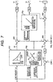
- Fig. 7 shows an integrated control device 8 of the present embodiment. According to the present embodiment, as shown in Fig.
- a measured compressor exit gas temperature is input to the function generator FG3 and then a spray amount is calculated so as to suppress a deflection of the compressor exit gas temperature before the gas turbine exhaust gas is recirculated or preferably so that the temperature is constant. It is so controlled so that the spray amount is increased as the exit temperature rises.
- the spray amount (supply water amount) adjusting valve 12 is controlled.
- the fuel flow rate of a case in which the liquid droplets are sprayed is correctively controlled by applying a spray amount signal to a fuel flow rate signal obtained from the load request signal Ld and actual load L, thereby achieving a constant combustion temperature.
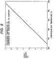
- Fig. 8 shows a control line for calculating a compressor exit gas temperature before the gas turbine exhaust gas recirculation from a compressor exit gas temperature when the atmospheric temperature is 15°C.
- the compressor exit gas temperature is about 450°C when the gas turbine exhaust gas recirculation amount is 10%, by carrying out about 2.5% spray at the compressor intake, the compressor exit gas temperature constant operation before carrying out the gas turbine exhaust gas recirculation is made possible.
- the control line contains the atmospheric temperature as a parameter.
- a third embodiment will be described with reference to Fig. 1 and other diagrams. Its basic structure is the same as the structure of the first embodiment.
- a feature of the present embodiment exists in that a detection unit for detecting a mixing gas temperature at the compressor intake is provided and the spray amount is controlled depending on a temperature provided by that temperature detection unit.
- the spray amount is controlled so as to obtain the compressor exit temperature before exhaust gas recirculation.
- a fourth embodiment will be described with reference to Fig. 1 and other diagrams. Its basic structure is the same as that of the first embodiment.
- a feature of the present embodiment exists in that the spray amount is controlled by the integrated control device 8 according to a signal from a combined cycle plant load measuring apparatus.
- the load is often measured on regular operation as well and can be controlled easily because such a signal is available.
- a point of the present embodiment is a gas turbine apparatus not provided with a exhaust heat recovery boiler 4 supplied with exhaust gas from the gas turbine 3 and a steam turbine supplied with steam generated in the gas turbine exhaust heat recovery boiler 4.
- a spray unit for introducing liquid droplets in the compressor in which the mixing gas comprising gas turbine exhaust gas passing through the aforementioned recirculation path and air flows so as to vaporize the introduced liquid droplets during a flow in the compressor.
- the amount of the gas turbine exhaust gas to be returned to the compressor is adjusted corresponding to the load change of the aforementioned combined cycle plant.
- the liquid droplets are sprayed from the spray unit into the compressor in which the mixing gas comprising gas turbine exhaust gas passing through the aforementioned recirculation path and air flows so as to vaporize the introduced liquid droplets during a flow in the compressor.
- a spray amount control unit for controlling a spray amount corresponding to the aforementioned recirculation amount is also provided. Corresponding to the load on the combined cycle plant, it is so controlled as to spray more when the load is low rather than high.
- the spray amount is controlled corresponding to a change of the temperature of the mixing gas to be introduced to a compressor intake.
- the spray amount is so controlled as to be more when the mixing gas temperature is high rather than low.
- the temperature of the internal gas in the compressor can be reduced so that the characteristic of the compressor can be improved.
- the gas turbine exhaust gas recirculation amount can be increased so that the partial load operation range can be expanded.
- the heat efficiency can be improved higher than the gas turbine exhaust gas recirculation type gas turbine apparatus.
- a sixth embodiment of the present invention will be described with reference to FIGs. 11-16.
- the spray amount and recirculation amount are controlled depending on a temperature of exhaust gas to be introduced to the compressor.
- FIG. 11 shows a schematic view of this embodiment. Basically, this is of the same structure as the schematic view of the first embodiment.
- recirculating exhaust gas is introduced from a downstream side of the gas turbine exhaust heat recovery boiler 4.
- the pipe 9 for fetching out a part of exhaust gas of the gas turbine 3 may be provided at any place of the gas turbine exhaust heat recovery boiler, exhaust heat recovery boiler intake portion and outlet portion, it should be provided at the gas turbine exhaust heat recovery boiler outlet portion like this embodiment so as to make effective use of heat in the gas turbine exhaust gas.
- the operation ends include a fuel amount control valve 7 for controlling the fuel amount to be charged on the combustion chamber 2, a recirculation amount control means 10, a spray amount adjusting valve 12 and air flow amount adjusting valve 15 and these operation ends are controlled depending on an operation signal dispatched from an integrated control unit 8. Such an operation enables to control the power generation efficiency of the combined plant.
- a signal of a temperature detection unit 18 for detecting the temperature of air to be supplied to the compressor is transmitted to the integrated control unit.
- a signal of the humidity detection unit 19 is transmitted.
- the temperature detection unit 18 and humidity detection unit 19 can be provided at a converging portion of the recirculation exhaust gas or in the upstream of the spray nozzle 11.
- the entire plant is controlled by an instruction from the integrated control unit 8 so as to control the recirculation amount, fuel amount, air amount and water spray amount appropriately.
- a compressor intake temperature is inputted to raise plant efficiency so that the plant load is controlled so as to be constant.
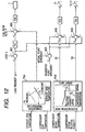
- FIG. 12 shows an example of the control mechanism of the integrated control unit.
- a difference between a load request signal Ld and actual load L is obtained by a subtractor AD1 and then a fuel amount object signal Fd is obtained by an adjuster PI1.
- a difference between the fuel amount object signal Fd and actual fuel amount F is obtained by the subtractor AD2 and a fuel amount control valve 7 is adjusted by an adjuster PI2 so as to determine an amount of fuel to be charged on the combustion chamber.
- the fuel amount can be controlled in this manner. For example, this control is capable of increasing the amount of fuel to be charged on the combustion chamber 2 as the load increases.
- an instruction signal S1 on the recirculation amount is dispatched by a function generator 3 (FG12).
- This signal is supplied to an adjuster P13 so as to control the recirculation control means 10.
- the function generator 3 (FG12) generate, an instruction signal S2 on the spray amount from a spray nozzle 11.
- This signal is supplied to an adjuster P14 and controls a supply water amount adjusting valve 12 and an air flow adjusting valve 15 so as to control a spray amount of droplet from the spray nozzle 11. It is favorable to estimate a combustion temperature from the gas turbine exhaust gas temperature and compressor outlet pressure by means of a function generator 4 (FG12) and apply this value to the subtractor AD2 to carry out corrective control of the fuel amount.
- the fuel is adjusted corresponding to that change thereby suppressing a change in combustion temperature so as to make the combustion temperature constant.
- the combustion temperature may change in actual operation. Therefore, if the change in the combustion temperature is controlled based on an actual combustion temperature estimated from the actual exhaust gas temperature of a gas turbine and compressor discharge pressure, it is possible to carry out the operation while suppressing a drop of the combustion temperature at the time of water spray or recirculation. This prevents a drop of efficiency due to a decrease of the fuel temperature.
- the function generator 3 calculates a combustion temperature according to a signal from the gas turbine exhaust gas temperature detector 24 and a signal from a compressor discharged air temperature detector 23 and dispatches a signal to the AD2. For example, it is possible to calculate so that the combustion temperature is higher when the gas turbine exhaust gas temperature is high than when it is low or the same when the compressor discharge pressure is high than when it is low.
- a numeral value corresponding to the combustion temperature can be outputted by other means.
- the function generator 4 controls a spray amount of a spray nozzle 11 based on a compressor intake temperature. Further, it controls the recirculation amount.
- the spray amount and the like is preferred to be corrected based on the compressor intake humidity.
- the spray amount (or a limit value of the spray amount) increases as the temperature rises, so that the spray amount (or a limit value of the spray amount) can be adjusted so as to be larger when the humidity is low than when it is high.
- the recirculation is stopped and the spray of the droplets from the spray unit is stopped. If the detected temperature is in a third temperature region which is higher than the second temperature region, the recirculation is stopped and the spray unit is controlled to spray the droplets. It is desirable to get a upper limit and lower limit of a region in which a high combined plant efficiency is ensured, so that they are set to a change temperature between the first temperature region and second temperature region and a change temperature between the second temperature region and third temperature region. It is desirable to set the aforementioned respective temperatures from a range between 15°C and 22°C which ensures a high combined plant efficiency. If some plant deviates from this region, it is desirable to set these values depending on the plant.
- the recirculation amount and water spray amount are controlled so as to reach such a compressor intake temperature allowing the plant efficiency to be maximized and realize a constant load on the plant at all times.
- the function generator FG3 to which the compressor intake temperature is to be inputted is requested to dispatch a signal S1 which increases the recirculation rate as the intake temperature decreases.
- This signal S1 is supplied to the adjuster PI3 so as to control the recirculation control means 10.
- the signal S1 controls the recirculation amount to a desired output and can be used as a limit value of the recirculation amount.
- the function generator FG1 to which the compressor intake temperature and humidity are to be inputted is requested to dispatch a signal S2 which increases the spray rate as the intake air temperature rises or the relative humidity lowers.
- This signal S2 is supplied to the adjuster PI4 so as to control the water supply amount adjusting valve 12 and air flow amount adjusting valve 15.
- the compressor intake temperature can be kept constant by the recirculation amount control and spray amount control or the change can be suppressed excellently.
- the combined plant can be operated at a high plant efficiency.
- the control in the second temperature region in which the combined plant efficiency is high can be facilitated. Despite a change in the atmospheric temperature, a desired output can be obtained at a high efficiency.
- the high efficiency operation will be described.
- the plant efficiency is determined by the plant output (gas turbine output and steam turbine output) and fuel flow rate.
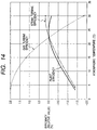
- FIG. 14 shows an efficiency characteristic depending on the atmospheric temperature. If the atmospheric temperature drops below an atmospheric temperature allowing the plant efficiency to be maximized, the compressor intake weight flow rate increases. On the other hand, because the combustion temperature is constant, the fuel flow rate increases so that the gas turbine output also increases.
- the steam cycle is influenced by an increase of the gas turbine exhaust gas flow rate accompanied by an increase of the compressor intake weight flow rate and a drop of the gas turbine exhaust gas temperature due to a drop of the atmospheric temperature, the steam turbine output is increased because the influence by the gas turbine exhaust gas flow rate is large.
- the increase rate of the steam turbine output is smaller than that of the gas turbine output, the increase rate of the plant output is small so that the plant efficiency is also small.
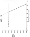
- FIG. 15 shows a relation between the atmospheric temperature and plant output.
- the plant output changes depending on the atmospheric temperature and as the atmospheric temperature lowers, the plant output increases as shown by broken line.
- each approved output is specified and therefore it is considered that an operation exceeding that limit is not carried out. Therefore, if the approved output is reached, the approved output constant operation is continued irrespective of the atmospheric temperature as shown by a solid line and at this time, the gas turbine is operated with a partial load. If the atmospheric temperature rises, the gas turbine compressor intake weight flow rate and fuel flow rate are reduced so that the plant output drops.
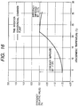
- FIG. 16 shows a plant efficiency characteristic depending on the atmospheric temperature.
- the gas turbine is operated with its partial load, and therefore the plant efficiency is reduced extremely.
- the gas turbine intake temperature can be the same as the atmospheric temperature allowing a high plant efficiency.
- the plant efficiency can be improved by about 0-1.5% in terms of its relative value. If the compressor intake temperature is higher than the atmospheric temperature in which the plant efficiency is high, the plant efficiency can be improved by about 0.1% in terms of the relative value by a spray amount 0-0.2% the gas turbine intake flow rate by spraying droplets from the water spray nozzle 11 to gas turbine intake air. Therefore, if the atmospheric temperature is low, by returning a part of the gas turbine exhaust gas to the compressor intake by the gas turbine exhaust gas recirculation system, the compressor intake weight flow rate can be reduced so as to reduce the plant output. Therefore, the gas turbine can be operated at the approved output constant rating without being operated with its partial load.
- the plant output can be increased by increasing the compressor intake weight flow rate by the intake air water spray system, so that the constant loaded operation can be achieved at a high efficiency without depending on the atmospheric temperature.
- the seventh embodiment will be described with reference to FIGs. 11-16.
- the seventh embodiment is capable of having the same structure as the sixth embodiment except that: If the detected temperature of air supplied to the compressor is in the first temperature region under control of the sixth embodiment, the aforementioned recirculation is carried out and the spray of droplets from the spray unit is stopped. If the detected temperature is in the second temperature region which is higher than the first temperature region, the aforementioned recirculation is carried out and the spray unit is controlled to spray droplets. If the detected temperature is in the third temperature region which is higher than the second temperature region, the aforementioned recirculation is stopped and the spray unit is controlled to spray droplets.
- the change temperature between the first temperature region and second temperature region, and the change temperature between the second temperature region and third temperature region can be set in the same way as in the sixth embodiment.
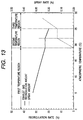
- FIG. 13 shows an example of the control line.
- the recirculation amount increases as the compressor intake temperature lowers.
- the gas turbine exhaust gas is recirculated and the aforementioned droplet spray from the water spray nozzle 11 is carried out.
- FIG. 13 shows a case in which the second temperature region is more than 19°C and less than 25°C.
- the second temperature region is divided to a high temperature side and a low temperature side relative to the set value.
- the set value is preferred to be determined with respect to such a value in which the combined plant efficiency is high. For example, it can be set in a range of 15 °C-22°C. Further the second temperature region can be set by providing the set value with an allowance of ⁇ 2°C - ⁇ 3°C.
- the aforementioned second temperature region should be set to a region in which the plant can be operated with stability.
- the compressor intake temperature allowance may be about 5°C.
- the recirculation amount is kept constant and the intake air water spray system is started.
- the spray amount (or a limit value of the spray amount) of droplets from the water spray nozzle is preferred to be set so as to larger when the temperature is higher.
- the spray amount can be controlled to such a compressor intake temperature in which a plant efficiency is increased when the load on the plant is kept constant. It is possible to so control that the recirculation amount is kept constant until the compressor intake temperature reaches a compressor intake temperature in which the plant efficiency is maximized and the spray amount increases as the compressor intake temperature rises.
- the recirculation amount is decreased when the temperature of air to be supplied to the compressor is high as compared to when it is low.
- the recirculation of the gas turbine exhaust gas is stopped and water is sprayed from the water spray nozzle 11.
- the spray amount increases as the compressor intake temperature rises.
- this embodiment is capable of largely contributing to an operation ensuring a high efficiency and suppressing a change in load (preferably, constant load operation) even if the external air temperature changes. Particularly, it is possible to easily suppress a change in the spray amount due to a change in the external air temperature and a output change due to a change in the recirculation amount.
- the eighth embodiment includes a carbon dioxide gas condensing mechanism for condensing carbon dioxide so as to reduce carbon dioxide (e.g., CO 2 ) in the gas turbine exhaust gas and a carbon dioxide gas removing unit 41 for reducing the concentration of carbon dioxide contained in the gas turbine exhaust gas, which contains the condensed carbon dioxide gas.
- carbon dioxide e.g., CO 2
- the concentration of carbon dioxide gas becomes higher than the conventional plant.
- the concentration of the carbon dioxide in the gas turbine exhaust gas becomes higher.
- the carbon dioxide removing efficiency also rises.
- the concentration of oxygen in the gas turbine exhaust gas becomes zero, namely the gas turbine exhaust gas recirculation rate is 75%, the concentration of carbon dioxide in the gas turbine exhaust gas becomes about four times as compared to the conventional plant.
- the transfer area can be reduced by 1/4.
- the carbon dioxide gas can be reduced by introducing the gas turbine exhaust gas containing the condensed carbon dioxide gas to the carbon dioxide gas removing unit 41. Therefore, as compared to a case when the carbon dioxide gas removing unit is only installed in the gas turbine plant, the carbon dioxide can be removed at a high efficiency. Further, if the same removing performance as the carbon dioxide gas removing unit of the conventional plant is ensured, the size of the carbon dioxide gas removing unit can be reduced.
- the size of the carbon dioxide gas removing unit to be installed on the flow path of the gas turbine exhaust gas can be reduced, the pressure loss can be suppressed thereby contributing to a high efficiency operation of the gas turbine.
- the gas turbine exhaust gas is recirculated so as to run the gas turbine according to this embodiment, carbon dioxide gas of a high concentration is generated and the gas turbine exhaust gas of a high concentration is introduced to the carbon dioxide gas removing unit.
- the gas turbine can be operated at a higher efficiency.
- the carbon dioxide can be removed at a high efficiency while achieving a high efficiency operation of the gas turbine, there is such a basic effect as forming a gas turbine or combined plant taking care of the environment and gentle to the environment.
- the spray nozzle 11 is preferred to be run as described in the aforementioned embodiment.
- the eighth embodiment can possess a structure of the sixth embodiment.
- the eighth embodiment contains a carbon dioxide gas removing unit 41a which is provided on an exhaust gas path 31 as well as the structure of the sixth embodiment.
- the gas turbine exhaust gas emitted from the gas turbine 3 is supplied to the upstream of the compressor 1 through a recirculating means 9.
- Mixing gas comprising air and recirculated exhaust gas is introduced to the compressor 1 so as to raise the pressure.
- the mixing gas discharged from the compressor 1 and fuel are introduced to the gas turbine chamber 2 and burnt together.
- gas turbine exhaust gas having a higher concentration of carbon dioxide than a plain gas turbine having no recirculating means is discharged from the gas turbine chamber 2 so as to drive the gas turbine 3.
- a part of the gas turbine exhaust gas having a high concentration of carbon dioxide is diverged to the recirculating means 9 and the remainder thereof is introduced to the carbon dioxide gas removing unit 41a installed on the gas turbine exhaust gas path 31 in the downstream of the diverging portion so that the concentration of the carbon dioxide is reduced. After the concentration of the carbon dioxide is reduced, the gas turbine exhaust gas is omitted to the air through a stack or the like.
- the carbon dioxide gas removing unit 41 of the present invention is installed on the gas turbine exhaust gas path 32 or recirculation means 9 between the gas turbine and the diverging portion of the recirculating means 9, the carbon dioxide concentration of the gas turbine exhaust gas to be supplied to the carbon dioxide gas removing unit 41 can be maintained at a high level.
- the carbon dioxide can be removed at a high efficiency.
- the size of the carbon dioxide gas removing unit 41 can be reduced while ensuring a desired performance. Due to the reduced size, the pressure loss in the gas turbine exhaust gas path can be reduced, thereby contributing to a high efficiency operation of the gas turbine.
- the recirculation amount is lower than 75% the flow rate of the gas turbine exhaust gag.
- the carbon dioxide gas removing unit 41 it is possible to use one having a carbon dioxide gas removing performance capable of reducing the concentration of carbon dioxide to be supplied to the carbon dioxide gas removing unit by 5%-10%.
- the carbon dioxide gas removing unit may be one using amine base absorptive agent.
- the carbon dioxide gas removing unit is preferred to be located in the downstream of the gas turbine exhaust heat recovery boiler from viewpoints of a more compact structure, material strength and the like.
- This unit may be disposed within the gas turbine exhaust heat recovery boiler from viewpoints of simplification of the apparatus on the gas turbine exhaust gas path.
- the ninth embodiment can employ a structure of the eighth embodiment.
- a carbon dioxide gas removing unit 41b is installed on the gas turbine exhaust gas path 32 between the gas turbine and the diverging portion to the recirculating means 9.
- the gas turbine exhaust gas emitted from the gas turbine 3 is supplied to the compressor 1 through the recirculating means 9.
- Mixing gas comprising air and recirculated exhaust gas is introduced to the compressor 1 so as to raise the pressure.
- the mixing gas discharged from the compressor 1 and fuel are introduced to the gas turbine chamber 2 and burnt together.
- gas turbine exhaust gas having a higher concentration of carbon dioxide than a plain gas turbine having no recirculating means is discharged from the gas turbine chamber 2 so as to drive the gas turbine 3.
- the gas turbine exhaust gas having a high concentration of carbon dioxide is introduced to the carbon dioxide gas removing unit 41b so as to reduce the concentration of the carbon dioxide gas.
- a part of the gas turbine exhaust gas in which the concentration of carbon dioxide is reduced is diverged to the recirculating means 9 and the remainder is emitted to the air through a stack or the like.
- the tenth embodiment can employ a structure of the eighth embodiment.
- a carbon dioxide gas removing unit 41c is installed as the recirculating means 9.
- the gas turbine exhaust gas emitted from the gas turbine 3 is supplied to the upstream of the compressor 1 through a recirculating means 9.
- Mixing gas comprising air and recirculated exhaust gas is introduced to the compressor 1 so as to raise the pressure.
- the mixing gas discharged from the compressor 1 and fuel are introduced to the gas turbine chamber 2 and burnt together.
- gas turbine exhaust gas having a higher concentration of carbon dioxide than a plain gas turbine having no recirculating means is discharged from the gas turbine chamber 2 so as to drive the gas turbine 3.
- a part of the gas turbine exhaust gas having a high concentration of carbon dioxide is diverged to the recirculating means 9 and the remainder thereof is emitted to the air through a stack or the like.
- the diverged exhaust gas to the recirculating means 9 is introduced to the carbon dioxide gas removing unit 41b, in which the concentration of the carbon dioxide is reduced. After the concentration of the carbon dioxide is reduced, the gas turbine exhaust gas is supplied to the compressor 1 again.
- the carbon dioxide gas removing unit 41 As described above, in addition to the basic effect of the eight embodiment, it is unnecessary to install the carbon dioxide gas removing unit 41 producing a pressure loss in a path for discharging the gas turbine exhaust gas to the air, thereby contributing to a high efficiency operation of the gas turbine. Further, the carbon dioxide gas removing unit 41c can be installed easily as well as when it is additionally installed on an existing gas turbine plant. Further, because the carbon dioxide gas removing unit 41c is installed separately from a system in which the gas turbine exhaust gas always flows, in the gas turbine plant using the recirculating means if necessary, the maintenance thereof is facilitated. Even in a case when the maintenance work on the carbon dioxide gas removing unit 41c is carried out, it is possible to carry out the maintenance work with the gas turbine operation being continued by shutting dawn the gas turbine exhaust gas flowing into the recirculating line.
Abstract
Description
Thus, the diameter of the liquid droplet is desired to be as small as possible from this viewpoint.
The
When a detected temperature of air supplied to the compressor is in a set first temperature region, the recirculation is carried out and the spray of droplets from the spray unit is stopped. If the detected temperature is in a second temperature region which is higher than the first temperature region, the recirculation is stopped and the spray of the droplets from the spray unit is stopped. If the detected temperature is in a third temperature region which is higher than the second temperature region, the recirculation is stopped and the spray unit is controlled to spray the droplets. It is desirable to get a upper limit and lower limit of a region in which a high combined plant efficiency is ensured, so that they are set to a change temperature between the first temperature region and second temperature region and a change temperature between the second temperature region and third temperature region. It is desirable to set the aforementioned respective temperatures from a range between 15°C and 22°C which ensures a high combined plant efficiency. If some plant deviates from this region, it is desirable to set these values depending on the plant.
This signal S1 is supplied to the adjuster PI3 so as to control the recirculation control means 10. The signal S1 controls the recirculation amount to a desired output and can be used as a limit value of the recirculation amount.
This signal S2 is supplied to the adjuster PI4 so as to control the water supply
Claims (21)
- An exhaust gas recirculation type gas turbine apparatus comprising: a compressor for compressing air; a combustion chamber for burning compression air exhausted from said compressor and fuel; a gas turbine driven by gas turbine exhaust gas from said combustion chamber; a recirculation path for recirculating a part of said gas turbine exhaust gas to an intake of said compressor; a recirculation amount control unit for adjusting an amount of gas turbine exhaust gas to be returned to the intake of said compressor corresponding to a change in load of said gas turbine; and a spray unit for introducing liquid droplets into an interior of said compressor in which mixing gas comprising gas turbine exhaust gas passing through said recirculation path and air flows so as to vaporize the introduced liquid droplet during a flow in said compressor.
- An exhaust gas recirculation type gas turbine apparatus comprising: a compressor for compressing air; a combustion chamber for burning compression air exhausted from said compressor and fuel; a gas turbine driven by gas turbine exhaust gal from said combustion chamber; a recirculation path for recirculating a part of said gas turbine exhaust gas to an intake of said compressor; a recirculation amount control unit for adjusting an amount of gas turbine exhaust gas to be returned to the intake of said compressor corresponding to a change in load of said gas turbine: and a spray unit for spraying liquid droplets over air supplied to said compressor and gas turbine exhaust gas passing through said recirculation path so as to introduce the liquid droplets into the compressor in which said air and said gas turbine exhaust gas flow so that said introduced liquid droplets are vaporized during a flow in said compressor.
- An exhaust gas recirculation type gas turbine apparatus comprising: a compressor for compressing air; a combustion chamber for burning compression air exhausted from said compressor and fuel; a gas turbine driven by gas turbine exhaust gas from said combustion chamber; a recirculation path for recirculating a part of said gas turbine exhaust gas to an intake of said compressor; a recirculation amount control unit for adjusting an amount of gas turbine exhaust gas to be returned to the intake of said compressor corresponding to a change in load of said gas turbine: and a spray unit for spraying liquid droplets having an average diameter of 30 µm or below so as to introduce the liquid droplets into the compressor in which mixing gas comprising gas turbine exhaust gas passing through said recirculation path and air flows, and said spray unit being disposed at the upstream of said compressor.
- An exhaust gas recirculation type gas turbine apparatus comprising; a compressor for compressing air; a combustion chamber for burning compression air exhausted from said compressor and fuel; a gas turbine driven by gas turbine exhaust gas from said combustion chamber; a recirculation path for recirculating a part of said gas turbine exhaust gas to an intake of said compressor: a recirculation amount control unit for adjusting an amount of gas turbine exhaust gas to be returned to the intake of said compressor corresponding to a change in load of said gas turbine; a spray unit for introducing liquid droplets into an interior of said compressor in which mixing gas comprising gas turbine exhaust gas passing through said recirculation path and air flows so as to vaporize the introduced liquid droplet during a flow in said compressor; and a spray amount control unit for controlling a spray amount of said liquid droplets corresponding to said recirculation amount.
- An exhaust gas recirculation type gal turbine apparatus comprising: a compressor for compressing air; a combustion chamber for burning compression air exhausted from said compressor and fuel; a gas turbine driven by gas turbine exhaust gas from said combustion chamber; a recirculation path for recirculating a part of said gas turbine exhaust gas to an intake of said compressor; a recirculation amount control unit for adjusting an amount of gas turbine exhaust gas to be returned to the intake of said compressor corresponding to a change in load of said gas turbine; a spray unit for introducing liquid droplets into an interior of said compressor in which mixing gas comprising gas turbine exhaust gas passing through said recirculation path and air flows so as to vaporize the introduced liquid droplet during a flow in said compressor: and a spray amount control unit for controlling a spray amount of said liquid droplets corresponding to a change in load of the gas turbine apparatus.
- An exhaust gas recirculation type gas turbine apparatus comprising: a compressor for compressing air; a combustion chamber for burning compression air exhausted from said compressor and fuel; a gas turbine driven by gas turbine exhaust gas from said combustion chamber; a recirculation path for recirculating a part of said gas turbine exhaust gas to an intake of said compressor; a recirculation amount control unit for adjusting an amount of gas turbine exhaust gas to be returned to the intake of said compressor corresponding to a change in load of said gas turbine; a spray unit for introducing liquid droplets into an interior of said compressor in which mixing gas comprising gas turbine exhaust gas passing through said recirculation path and air flows so as to vaporize the introduced liquid droplet during a flow in said compressor; and a spray amount control unit for controlling a spray amount of said liquid droplets corresponding to a change in the temperature of mixing gas to be introduced into said compressor.
- An exhaust gag recirculation type gas turbine comprising: a compressor for compressing air; a combustion chamber for burning compression air exhausted from said compressor and fuel; a gas turbine driven by gas turbine exhaust gas from said combustion chamber; a recirculation path for recirculating a part of said gas turbine exhaust gas to an intake of said compressor; a recirculation amount control unit for adjusting an amount of gas turbine exhaust gas to be returned to the intake of said compressor corresponding to a change in load of said gas turbine; a spray unit for introducing liquid droplets into an interior of said compressor in which mixing gas comprising gas turbine exhaust gas passing through said recirculation path and air flows so as to vaporize the introduced liquid droplet during a flow in said compressor; and a control unit for controlling said recirculation amount and a spray amount of said liquid droplets corresponding to the load so as to suppress a change in the combustion temperature of the combustion chamber under a gas turbine load of within the range of 50%-80%.
- An exhaust gas recirculation type combined cycle plant apparatus comprising: a compressor for compressing air; a combustion chamber for burning compression air exhausted from said compressor and fuel; a gas turbine driven by gas turbine exhaust gas from said combustion chamber; an exhaust heat recovery boiler 4 for recovering heat of the exhaust gas from the gas turbine 3 so as to generate steam by heat exchange with supplied water; a steam turbine 5 which is driven by the steam generated by the exhaust heat recovery boiler 4; a recirculation path for recirculating a part of said gas turbine exhaust gas to an intake of said compressor; a recirculation amount control unit for adjusting an amount of gas turbine exhaust gas to be returned to the intake of said compressor corresponding to a change in load of said gas turbine; a spray unit for introducing liquid droplets into an interior of said compressor in which mixing gas comprising gas turbine exhaust gas passing through said recirculation path and air flows so as to vaporize the introduced liquid droplet during a flow in said compressor; and a control unit for controlling said spray amount in a combined cycle plant load within the range of 50%-80% so that the recirculation amount is continuously increased as the load decreases.
- An exhaust gas recirculation type gas turbine apparatus comprising: a compressor for compressing air; a combustion chamber for burning compression air exhausted from said compressor and fuel; a gas turbine driven by gas turbine exhaust gas from said combustion chamber; a recirculation path for recirculating a part of said gas turbine exhaust gas to an intake of said compressor; a spray unit for introducing liquid droplets into an interior of said compressor in which mixing gas comprising gas turbine exhaust gas passing through said recirculation path and air flows so as to vaporize the introduced liquid droplet during a flow in said compressor; a temperature detector for detecting a temperature of air supplied to the compressor; and a control unit for controlling so that in the case of a first temperature region in which said detected temperature is set, said recirculation is executed and spray of droplets from said spray unit is stopped, in the case of a second temperature region which is higher than said first temperature region, said recirculation is executed and the spray of droplets from said spray unit is executed and in the case of a third temperature region which is higher than said second temperature region, said recirculation is stopped and the spray of droplets from said spray unit is executed.
- An exhaust gas recirculation type gas turbine apparatus comprising: a compressor for compressing air; a combustion chamber for burning compression air exhausted from said compressor and fuel; a gas turbine driven by gas turbine exhaust gas from said combustion chamber; a recirculation path for recirculating a part of said gas turbine exhaust gas to an intake of said compressor; a spray unit for introducing liquid droplets into an interior of said compressor in which mixing gas comprising gas turbine exhaust gas passing through said recirculation path and air flows so as to vaporize the introduced liquid droplet during a flow in said compressor; a temperature detector for detecting a temperature of air supplied to the compressor; and a control unit for controlling so that in the case of a first temperature region in which said detected temperature is set, said recirculation is executed and spray of droplets from said spray unit is stopped, in the case of a second temperature region which is higher than said first temperature region, said recirculation is stopped and the spray of droplets from said spray unit is stopped and in the case of a third temperature region which is higher than said second temperature region, said recirculation is stopped and the spray of droplets from said spray unit is executed.
- An exhaust gas recirculation type gas turbine apparatus according to claim 1 further comprising a control unit for controlling a spray amount of droplet from said spray unit depending on a humidity of air supplied to the compressor.
- An exhaust gas recirculation type gas turbine apparatus comprising: a compressor for compressing air; a gas turbine chamber for burning compression air exhausted from said compressor and fuel; a gas turbine driven by gas turbine exhaust gas from said gas turbine chamber; a recirculation path for recirculating a part of said gas turbine exhaust gas to an intake of said compressor; and a carbon dioxide gas removing unit installed in a flow path of gas turbine exhaust gas for reducing the concentration of carbon dioxide gas in the gas turbine exhaust gas discharged after air containing the recirculated exhaust gas is introduced to said gas turbine chamber.
- An exhaust gas recirculation type gas turbine apparatus according to claim 12 wherein said carbon dioxide gas removing means is disposed between a diverging portion of said recirculation path of said gas turbine exhaust gas path and an emitting portion for emitting said gas turbine exhaust gas to the air.
- An exhaust gas recirculation type gas turbine apparatus according to claim 12 wherein said carbon dioxide gas removing means is disposed between said gas turbine of said gas turbine exhaust gas path and a diverging portion of said recirculating path.
- An exhaust gas recirculation type gas turbine apparatus according to claim 12 wherein said carbon dioxide gas removing means is disposed on said recirculating path.
- An operation method of exhaust gas recirculation type gas turbine apparatus comprising the steps of: compressing air in a compressor; burning the compressed air and fuel; driving a gas turbine with gas turbine exhaust gal from said combustion chamber; recirculating a part of said gas turbine exhaust gas to an intake of said compressor through a recirculation path; adjusting an amount of gas turbine exhaust gas to be returned to the intake of said compressor corresponding to a change in the load of said gas turbine; and introducing liquid droplets into the compressor in which mixing gas comprising gas turbine exhaust gas passing through said recirculation path and air flows by spraying the liquid droplets from a spray unit so that the introduced liquid droplets are vaporized during a flow in said compressor.
- An operation method of exhaust gas recirculation type gas turbine apparatus comprising the steps of: compressing air in a compressor; burning the compressed air and fuel; driving a gas turbine with gas turbine exhaust gas from said combustion chamber; recirculating a part of said exhaust gas to an intake of said compressor through a recirculation path; adjusting an amount of gas turbine exhaust gas to be returned to the intake of said compressor corresponding to a change in the load of said gas turbine; controlling said recirculation amount corresponding to the load so as to suppress a change in the combustion temperature of the combustion chamber in a gas turbine load within the range of 50%-80%; and introducing liquid droplets into the compressor so as to suppress a rise of the temperature of the compression air at an exit of the compressor.
- An operation method of exhaust gas recirculation type combined cycle plant comprising the steps of: compressing air in a compressor; burning the compressed air and fuel; driving a gas turbine with gas turbine exhaust gas from said combustion chamber; an exhaust heat recovery boiler 4 for recovering heat of the exhaust gas from the gas turbine 3 so as to generate steam by heat exchange with supplied water; a steam turbine 5 which is driven by the steam generated by the exhaust heat recovery boiler 4; recirculating a part of said gas turbine exhaust gas to an intake of said compressor through a recirculation path; adjusting an amount of gas turbine exhaust gas to be returned to the intake of said compressor corresponding to a change in the load of said gas turbine; controlling said recirculation amount corresponding to the load so as to suppress a change in the combustion temperature of the combustion chamber in a combined cycle plant load within the range of 50%-80%; and controlling said spray amount of the liquid droplets to be vaporized during a flow in said compressor so that the recirculation amount is continuously increased as the load decreases.
- A running method of an exhaust gas recirculation type turbine apparatus comprising the steps of: compressing air by a compressor; burning the compressed air and fuel in a combustion chamber; driving a gas turbine by gas turbine exhaust gas from said combustion chamber; recirculating a part of said exhaust gas to an intake of said compressor through a recirculation path; spraying liquid droplets from a spray unit to introduce the liquid droplets into the compressor in which mixing gas comprising gas turbine exhaust gas and air flows through said recirculation path so as to vaporize the introduced liquid droplet during a flow in said compressor; detecting a temperature of air supplied to the compressor; and controlling so chat in the case of a first temperature region in which said detected temperature is set, said recirculation is executed and said spray is stopped, in the case of a second temperature region which is higher than said first temperature region, said recirculation is executed and said spray is executed and in the case of a third temperature region which is higher than said second temperature region, said recirculation is stopped and said spray is executed.
- A running method of an exhaust gas recirculation type turbine apparatus comprising the steps of: compressing air by a compressor; burning the compressed air and fuel in a combustion chamber; driving a gas turbine by gas turbine exhaust gas from said combustion chamber; recirculating a part of said exhaust gas to an intake of said compressor through a recirculation path; spraying liquid droplets from a spray unit to introduce the liquid droplets into the compressor in which mixing gas comprising gas turbine exhaust gas and air flows through said recirculation path so as to vaporize the introduced liquid droplet during a flow in said compressor; detecting a temperature of air supplied to the compressor; and controlling so that in the case of a first temperature region in which said detected temperature is set, said recirculation is executed and said spray is stopped, in the case of a second temperature region which is higher than said first temperature region, said recirculation is stopped and said spray is stopped and in the case of a third temperature region which is higher than said second temperature region, said recirculation is stopped and said spray is executed.
- An operation method of exhaust gas recirculation type combined cycle plant comprising the steps of: compressing air in a compressor; burning the compressed air and fuel in a gas turbine chamber; driving a gas turbine with gas turbine exhaust gas from said gas turbine chamber; recirculating a part of said gas turbine exhaust gas to an intake of said compressor through a recirculating path; and burning fuel with air containing said gas turbine exhaust gas recirculated in said gas turbine chamber so as to reduce the concentration of carbon dioxide gas in gas turbine exhaust gas discharged after the burning.
Applications Claiming Priority (3)
| Application Number | Priority Date | Filing Date | Title |
|---|---|---|---|
| JP17146697 | 1997-06-27 | ||
| JP17146697 | 1997-06-27 | ||
| JP171466/97 | 1997-06-27 |
Publications (2)
| Publication Number | Publication Date |
|---|---|
| EP0887530A2 true EP0887530A2 (en) | 1998-12-30 |
| EP0887530A3 EP0887530A3 (en) | 2000-08-09 |
Family
ID=15923636
Family Applications (1)
| Application Number | Title | Priority Date | Filing Date |
|---|---|---|---|
| EP98111886A Withdrawn EP0887530A3 (en) | 1997-06-27 | 1998-06-26 | Gas turbine with exhaust gas recirculation |
Country Status (4)
| Country | Link |
|---|---|
| US (3) | US6256976B1 (en) |
| EP (1) | EP0887530A3 (en) |
| KR (1) | KR19990007373A (en) |
| CN (1) | CN1143953C (en) |
Cited By (21)
| Publication number | Priority date | Publication date | Assignee | Title |
|---|---|---|---|---|
| EP1203866A2 (en) * | 2000-11-06 | 2002-05-08 | General Electric Company | Apparatus and methods for controlling the supply of water mist to a gas-turbine compressor |
| EP1231369A2 (en) | 2001-02-07 | 2002-08-14 | General Electric Company | Gas turbine control system compensating water content in combustion air |
| WO2003048544A1 (en) * | 2001-12-06 | 2003-06-12 | Alstom Technology Ltd | Method and apparatus for achieving power augmentation in gas turbines using wet compression |
| WO2003048545A1 (en) * | 2001-12-06 | 2003-06-12 | Alstom Technology Ltd | Method and apparatus for achieving power augmentation in gas turbines using wet compression |
| WO2004033872A1 (en) * | 2002-10-08 | 2004-04-22 | Kawasaki Jukogyo Kabushiki Kaisha | Atmospheric pressure combustion turbine system |
| WO2004083615A1 (en) | 2003-03-18 | 2004-09-30 | Fluor Corporation | Humid air turbine cycle with carbon dioxide recovery |
| EP1632719A2 (en) * | 2004-09-07 | 2006-03-08 | General Electronic Company | System and method for improving thermal efficiency of dry low emissions (lean premix) combustor assemblies |
| ITMI20082161A1 (en) * | 2008-12-05 | 2010-06-06 | Ansaldo Energia Spa | DEVICE AND METHOD FOR THE CONTROL OF THE EMISSIONS OF A PLANT FOR THE PRODUCTION OF ELECTRICITY |
| EP2368023A2 (en) * | 2008-12-24 | 2011-09-28 | Alstom Technology Ltd | Power plant with co2 capture |
| WO2011139444A1 (en) * | 2010-04-30 | 2011-11-10 | General Electric Company | Method for reducing co2 emissions in a combustion stream and industrial plants utilizing the same |
| FR2966509A1 (en) * | 2010-10-21 | 2012-04-27 | Gen Electric | SYSTEM FOR CONTROLLING A SEMI-CLOSED ENERGY CYCLE SYSTEM |
| EP2503106A1 (en) * | 2011-03-22 | 2012-09-26 | Alstom Technology Ltd | Gas turbine power plant with flue gas recirculation and oxygen-depleted cooling gas |
| CN102996252A (en) * | 2011-09-07 | 2013-03-27 | 阿尔斯通技术有限公司 | Method for operating a combined cycle power plant |
| EP1752616A3 (en) * | 2005-03-31 | 2013-07-03 | Alstom Technology Ltd | Gas turbine plant |
| EP2184464A3 (en) * | 2008-10-27 | 2013-07-03 | General Electric Company | An inlet system for a gas turbine with EGR system |
| WO2014106265A3 (en) * | 2012-12-31 | 2015-01-22 | General Electric Company | Gas turbine load control system |
| EP3170995A1 (en) * | 2015-11-23 | 2017-05-24 | Siemens Aktiengesellschaft | Combined cycle power plant and related method of operation |
| RU180005U1 (en) * | 2017-04-04 | 2018-05-30 | Федеральное государственное бюджетное военное образовательное учреждение высшего образования "Черноморское высшее военно-морское ордена Красной Звезды училище имени П.С. Нахимова" Министерства обороны Российской Федерации | Gas-turbine non-volatile installation of underwater vehicle |
| FR3073002A1 (en) * | 2017-10-26 | 2019-05-03 | Safran Helicopter Engines | GUIDE VANE WITH COOLANT INJECTION CIRCUIT |
| WO2021093806A1 (en) * | 2019-11-12 | 2021-05-20 | 广东第二师范学院 | Intelligent self-checking gas turbine based on variable fuzzy membership degree and detection and analysis method therefor |
| CN113638807A (en) * | 2021-09-15 | 2021-11-12 | 西安热工研究院有限公司 | Heating system and method for bypass auxiliary cylinder cutting of gas-steam combined cycle unit |
Families Citing this family (181)
| Publication number | Priority date | Publication date | Assignee | Title |
|---|---|---|---|---|
| US6777823B1 (en) * | 2001-05-21 | 2004-08-17 | Active Power, Inc. | Integrated continuous power system assemblies having multiple nozzle block segments |
| FR2825935B1 (en) * | 2001-06-14 | 2003-08-22 | Inst Francais Du Petrole | LOW CO2 EMISSIONS POWER GENERATOR AND ASSOCIATED METHOD |
| DE50209742D1 (en) * | 2002-01-07 | 2007-04-26 | Alstom Technology Ltd | METHOD FOR OPERATING A GUESTURBOGROUP |
| US6820689B2 (en) | 2002-07-18 | 2004-11-23 | Production Resources, Inc. | Method and apparatus for generating pollution free electrical energy from hydrocarbons |
| JP3702267B2 (en) * | 2002-11-13 | 2005-10-05 | 三菱重工業株式会社 | Single-shaft combined cycle plant |
| DE10256193A1 (en) * | 2002-12-02 | 2004-06-09 | Alstom Technology Ltd | Method for controlling the liquid injection into an inflow channel of an engine or machine |
| US7637093B2 (en) * | 2003-03-18 | 2009-12-29 | Fluor Technologies Corporation | Humid air turbine cycle with carbon dioxide recovery |
| EP1462633B1 (en) * | 2003-03-28 | 2013-10-30 | Siemens Aktiengesellschaft | Method of controlling the hot gas temperature of a gas turbine |
| US7513099B2 (en) * | 2003-03-28 | 2009-04-07 | Siemens Aktiengesellschaft | Temperature measuring device and regulation of the temperature of hot gas of a gas turbine |
| DE10325111A1 (en) * | 2003-06-02 | 2005-01-05 | Alstom Technology Ltd | Method for generating energy in a gas turbine comprehensive power generation plant and power plant for performing the method |
| JP3930462B2 (en) * | 2003-08-01 | 2007-06-13 | 株式会社日立製作所 | Single-shaft combined cycle power generation facility and operation method thereof |
| DE102004012080A1 (en) * | 2004-03-12 | 2005-10-13 | Alstom Technology Ltd | Apparatus and method for heating a gas stream |
| DE102004039164A1 (en) * | 2004-08-11 | 2006-03-02 | Alstom Technology Ltd | Method for generating energy in a gas turbine comprehensive power generation plant and power generation plant for performing the method |
| US7269953B2 (en) * | 2004-08-27 | 2007-09-18 | Siemens Power Generation, Inc. | Method of controlling a power generation system |
| US7137257B2 (en) * | 2004-10-06 | 2006-11-21 | Praxair Technology, Inc. | Gas turbine power augmentation method |
| KR20080095843A (en) * | 2006-01-27 | 2008-10-29 | 보그워너 인코포레이티드 | Mixing unit for low pressure-egr condensate into the compressor |
| US7895822B2 (en) * | 2006-11-07 | 2011-03-01 | General Electric Company | Systems and methods for power generation with carbon dioxide isolation |
| US7827778B2 (en) * | 2006-11-07 | 2010-11-09 | General Electric Company | Power plants that utilize gas turbines for power generation and processes for lowering CO2 emissions |
| US7739864B2 (en) * | 2006-11-07 | 2010-06-22 | General Electric Company | Systems and methods for power generation with carbon dioxide isolation |
| JP2008121513A (en) * | 2006-11-10 | 2008-05-29 | Mitsubishi Heavy Ind Ltd | Gas turbine power generation system and method of detecting calorie abnormality thereof |
| US20080141645A1 (en) * | 2006-12-14 | 2008-06-19 | General Electric Company | System and method for low emissions combustion |
| WO2008090168A1 (en) * | 2007-01-25 | 2008-07-31 | Shell Internationale Research Maatschappij B.V. | Process for reducing carbon dioxide emission in a power plant |
| US20090320440A1 (en) * | 2007-02-22 | 2009-12-31 | General Electric Company | Wet compression systems in turbine engines |
| US8850789B2 (en) * | 2007-06-13 | 2014-10-07 | General Electric Company | Systems and methods for power generation with exhaust gas recirculation |
| US20090056342A1 (en) * | 2007-09-04 | 2009-03-05 | General Electric Company | Methods and Systems for Gas Turbine Part-Load Operating Conditions |
| US9404418B2 (en) * | 2007-09-28 | 2016-08-02 | General Electric Company | Low emission turbine system and method |
| US7861511B2 (en) * | 2007-10-30 | 2011-01-04 | General Electric Company | System for recirculating the exhaust of a turbomachine |
| US7536252B1 (en) * | 2007-12-10 | 2009-05-19 | General Electric Company | Method and system for controlling a flowrate of a recirculated exhaust gas |
| US8572944B2 (en) * | 2007-12-19 | 2013-11-05 | General Electric Company | Prime mover for an exhaust gas recirculation system |
| US9410479B2 (en) * | 2007-12-19 | 2016-08-09 | General Electric Company | Method for adjusting the operation of a turbomachine receiving a recirculated exhaust gas |
| US20090158739A1 (en) * | 2007-12-21 | 2009-06-25 | Hans-Peter Messmer | Gas turbine systems and methods employing a vaporizable liquid delivery device |
| US8051638B2 (en) * | 2008-02-19 | 2011-11-08 | General Electric Company | Systems and methods for exhaust gas recirculation (EGR) for turbine engines |
| US20090235634A1 (en) * | 2008-03-24 | 2009-09-24 | General Electric Company | System for extending the turndown range of a turbomachine |
| CN104098070B (en) | 2008-03-28 | 2016-04-13 | 埃克森美孚上游研究公司 | Low emission power generation and hydrocarbon recovery system and method |
| CN101981272B (en) | 2008-03-28 | 2014-06-11 | 埃克森美孚上游研究公司 | Low emission power generation and hydrocarbon recovery systems and methods |
| US8479505B2 (en) | 2008-04-09 | 2013-07-09 | Sustainx, Inc. | Systems and methods for reducing dead volume in compressed-gas energy storage systems |
| US8448433B2 (en) | 2008-04-09 | 2013-05-28 | Sustainx, Inc. | Systems and methods for energy storage and recovery using gas expansion and compression |
| US8240140B2 (en) | 2008-04-09 | 2012-08-14 | Sustainx, Inc. | High-efficiency energy-conversion based on fluid expansion and compression |
| US8037678B2 (en) | 2009-09-11 | 2011-10-18 | Sustainx, Inc. | Energy storage and generation systems and methods using coupled cylinder assemblies |
| US7802426B2 (en) | 2008-06-09 | 2010-09-28 | Sustainx, Inc. | System and method for rapid isothermal gas expansion and compression for energy storage |
| US20100307156A1 (en) | 2009-06-04 | 2010-12-09 | Bollinger Benjamin R | Systems and Methods for Improving Drivetrain Efficiency for Compressed Gas Energy Storage and Recovery Systems |
| US8474255B2 (en) | 2008-04-09 | 2013-07-02 | Sustainx, Inc. | Forming liquid sprays in compressed-gas energy storage systems for effective heat exchange |
| US8250863B2 (en) | 2008-04-09 | 2012-08-28 | Sustainx, Inc. | Heat exchange with compressed gas in energy-storage systems |
| US8677744B2 (en) | 2008-04-09 | 2014-03-25 | SustaioX, Inc. | Fluid circulation in energy storage and recovery systems |
| US8359856B2 (en) | 2008-04-09 | 2013-01-29 | Sustainx Inc. | Systems and methods for efficient pumping of high-pressure fluids for energy storage and recovery |
| US8225606B2 (en) | 2008-04-09 | 2012-07-24 | Sustainx, Inc. | Systems and methods for energy storage and recovery using rapid isothermal gas expansion and compression |
| EP2280841A2 (en) | 2008-04-09 | 2011-02-09 | Sustainx, Inc. | Systems and methods for energy storage and recovery using compressed gas |
| US7958731B2 (en) | 2009-01-20 | 2011-06-14 | Sustainx, Inc. | Systems and methods for combined thermal and compressed gas energy conversion systems |
| US8397482B2 (en) * | 2008-05-15 | 2013-03-19 | General Electric Company | Dry 3-way catalytic reduction of gas turbine NOx |
| US20100003123A1 (en) * | 2008-07-01 | 2010-01-07 | Smith Craig F | Inlet air heating system for a gas turbine engine |
| US9297306B2 (en) * | 2008-09-11 | 2016-03-29 | General Electric Company | Exhaust gas recirculation system, turbomachine system having the exhaust gas recirculation system and exhaust gas recirculation control method |
| SG195533A1 (en) | 2008-10-14 | 2013-12-30 | Exxonmobil Upstream Res Co | Methods and systems for controlling the products of combustion |
| US8534073B2 (en) * | 2008-10-27 | 2013-09-17 | General Electric Company | System and method for heating a fuel using an exhaust gas recirculation system |
| CH699804A1 (en) * | 2008-10-29 | 2010-04-30 | Alstom Technology Ltd | Gas turbine plant with exhaust gas recirculation and method for operating such a plant. |
| EP2248999A1 (en) * | 2008-12-24 | 2010-11-10 | Alstom Technology Ltd | Power plant with CO2 capture |
| US20100180565A1 (en) * | 2009-01-16 | 2010-07-22 | General Electric Company | Methods for increasing carbon dioxide content in gas turbine exhaust and systems for achieving the same |
| WO2010105155A2 (en) | 2009-03-12 | 2010-09-16 | Sustainx, Inc. | Systems and methods for improving drivetrain efficiency for compressed gas energy storage |
| US8365530B2 (en) * | 2009-06-03 | 2013-02-05 | General Electric Company | System for conditioning the airflow entering a turbomachine |
| US8104274B2 (en) | 2009-06-04 | 2012-01-31 | Sustainx, Inc. | Increased power in compressed-gas energy storage and recovery |
| SG176670A1 (en) | 2009-06-05 | 2012-01-30 | Exxonmobil Upstream Res Co | Combustor systems and methods for using same |
| CH701236A1 (en) * | 2009-06-09 | 2010-12-15 | Alstom Technology Ltd | Device for sound damping in a flow channel of a gas turbine having apparatus for supplying recirculated exhaust gases elements into the intake air. |
| CH701235A1 (en) * | 2009-06-09 | 2010-12-15 | Alstom Technology Ltd | Apparatus for mixing fresh intake air with recirculated exhaust air in a gas turbine. |
| CH701803A1 (en) | 2009-09-03 | 2011-03-15 | Alstom Technology Ltd | Gas turbine group and method for operating such a gas turbine group. |
| EP2305363A1 (en) * | 2009-09-29 | 2011-04-06 | Alstom Technology Ltd | Power plant for CO2 capture |
| EP2305364A1 (en) * | 2009-09-29 | 2011-04-06 | Alstom Technology Ltd | Power plant for CO2 capture |
| WO2011056855A1 (en) | 2009-11-03 | 2011-05-12 | Sustainx, Inc. | Systems and methods for compressed-gas energy storage using coupled cylinder assemblies |
| EA023673B1 (en) | 2009-11-12 | 2016-06-30 | Эксонмобил Апстрим Рисерч Компани | Low emission power generation and hydrocarbon recovery system and method |
| US20110138766A1 (en) * | 2009-12-15 | 2011-06-16 | General Electric Company | System and method of improving emission performance of a gas turbine |
| EP2348256A1 (en) * | 2010-01-26 | 2011-07-27 | Alstom Technology Ltd | Method for operating a gas turbine and gas turbine |
| US8171728B2 (en) | 2010-04-08 | 2012-05-08 | Sustainx, Inc. | High-efficiency liquid heat exchange in compressed-gas energy storage systems |
| US8191362B2 (en) | 2010-04-08 | 2012-06-05 | Sustainx, Inc. | Systems and methods for reducing dead volume in compressed-gas energy storage systems |
| US8234863B2 (en) | 2010-05-14 | 2012-08-07 | Sustainx, Inc. | Forming liquid sprays in compressed-gas energy storage systems for effective heat exchange |
| DE102011102720B4 (en) | 2010-05-26 | 2021-10-28 | Ansaldo Energia Switzerland AG | Combined cycle power plant with exhaust gas recirculation |
| CH703218A1 (en) * | 2010-05-26 | 2011-11-30 | Alstom Technology Ltd | Method of operating a combined cycle with flue gas recirculation and power plant. |
| US9003761B2 (en) | 2010-05-28 | 2015-04-14 | General Electric Company | System and method for exhaust gas use in gas turbine engines |
| JP5913305B2 (en) | 2010-07-02 | 2016-04-27 | エクソンモービル アップストリーム リサーチ カンパニー | Low emission power generation system and method |
| PL2588727T3 (en) | 2010-07-02 | 2019-05-31 | Exxonmobil Upstream Res Co | Stoichiometric combustion with exhaust gas recirculation and direct contact cooler |
| BR112012031153A2 (en) | 2010-07-02 | 2016-11-08 | Exxonmobil Upstream Res Co | low emission triple-cycle power generation systems and methods |
| MY156099A (en) * | 2010-07-02 | 2016-01-15 | Exxonmobil Upstream Res Co | Systems and methods for controlling combustion of a fuel |
| JP5906555B2 (en) | 2010-07-02 | 2016-04-20 | エクソンモービル アップストリーム リサーチ カンパニー | Stoichiometric combustion of rich air by exhaust gas recirculation system |
| WO2012018458A1 (en) | 2010-08-06 | 2012-02-09 | Exxonmobil Upstream Research Company | System and method for exhaust gas extraction |
| EP2601393B1 (en) | 2010-08-06 | 2020-01-15 | Exxonmobil Upstream Research Company | Systems and methods for optimizing stoichiometric combustion |
| US8495872B2 (en) | 2010-08-20 | 2013-07-30 | Sustainx, Inc. | Energy storage and recovery utilizing low-pressure thermal conditioning for heat exchange with high-pressure gas |
| EP2610465B1 (en) * | 2010-08-27 | 2019-11-20 | Mitsubishi Hitachi Power Systems, Ltd. | Solar gas turbine system |
| US8166766B2 (en) | 2010-09-23 | 2012-05-01 | General Electric Company | System and method to generate electricity |
| US9359953B2 (en) * | 2010-09-30 | 2016-06-07 | Mitsubishi Hitachi Power Systems, Ltd. | Combined cycle power plant with solar assisted cooling of compressor inlet air |
| DE102011115364A1 (en) * | 2010-10-19 | 2012-04-19 | Alstom Technology Ltd. | power plant |
| EP2444631A1 (en) * | 2010-10-19 | 2012-04-25 | Alstom Technology Ltd | Power plant and method for its operation |
| DE102011115365A1 (en) * | 2010-10-19 | 2012-04-19 | Alstom Technology Ltd. | power plant |
| US8726628B2 (en) | 2010-10-22 | 2014-05-20 | General Electric Company | Combined cycle power plant including a carbon dioxide collection system |
| US8578708B2 (en) | 2010-11-30 | 2013-11-12 | Sustainx, Inc. | Fluid-flow control in energy storage and recovery systems |
| US9074530B2 (en) * | 2011-01-13 | 2015-07-07 | General Electric Company | Stoichiometric exhaust gas recirculation and related combustion control |
| CH704381A1 (en) * | 2011-01-24 | 2012-07-31 | Alstom Technology Ltd | Method for operating a gas turbine power plant with flue gas recirculation and gas turbine power plant with exhaust gas recirculation. |
| TWI564474B (en) | 2011-03-22 | 2017-01-01 | 艾克頌美孚上游研究公司 | Integrated systems for controlling stoichiometric combustion in turbine systems and methods of generating power using the same |
| TWI563165B (en) | 2011-03-22 | 2016-12-21 | Exxonmobil Upstream Res Co | Power generation system and method for generating power |
| TWI593872B (en) | 2011-03-22 | 2017-08-01 | 艾克頌美孚上游研究公司 | Integrated system and methods of generating power |
| TWI563166B (en) | 2011-03-22 | 2016-12-21 | Exxonmobil Upstream Res Co | Integrated generation systems and methods for generating power |
| JP2014522460A (en) | 2011-05-17 | 2014-09-04 | サステインエックス, インコーポレイテッド | System and method for efficient two-phase heat transfer in a compressed air energy storage system |
| US8347600B2 (en) | 2011-08-25 | 2013-01-08 | General Electric Company | Power plant and method of operation |
| US8453461B2 (en) | 2011-08-25 | 2013-06-04 | General Electric Company | Power plant and method of operation |
| US8205455B2 (en) | 2011-08-25 | 2012-06-26 | General Electric Company | Power plant and method of operation |
| US8713947B2 (en) | 2011-08-25 | 2014-05-06 | General Electric Company | Power plant with gas separation system |
| US8245492B2 (en) | 2011-08-25 | 2012-08-21 | General Electric Company | Power plant and method of operation |
| US9127598B2 (en) | 2011-08-25 | 2015-09-08 | General Electric Company | Control method for stoichiometric exhaust gas recirculation power plant |
| US8453462B2 (en) | 2011-08-25 | 2013-06-04 | General Electric Company | Method of operating a stoichiometric exhaust gas recirculation power plant |
| US8266913B2 (en) | 2011-08-25 | 2012-09-18 | General Electric Company | Power plant and method of use |
| US8245493B2 (en) | 2011-08-25 | 2012-08-21 | General Electric Company | Power plant and control method |
| US8266883B2 (en) | 2011-08-25 | 2012-09-18 | General Electric Company | Power plant start-up method and method of venting the power plant |
| US8720179B2 (en) * | 2011-10-07 | 2014-05-13 | General Electric Company | Power plant including an exhaust gas recirculation system for injecting recirculated exhaust gases in the fuel and compressed air of a gas turbine engine |
| US20130091836A1 (en) | 2011-10-14 | 2013-04-18 | Sustainx, Inc. | Dead-volume management in compressed-gas energy storage and recovery systems |
| WO2013092411A1 (en) * | 2011-12-19 | 2013-06-27 | Alstom Technology Ltd | Control of the gas composition in a gas turbine power plant with flue gas recirculation |
| CN104428490B (en) | 2011-12-20 | 2018-06-05 | 埃克森美孚上游研究公司 | The coal bed methane production of raising |
| US20130160456A1 (en) * | 2011-12-22 | 2013-06-27 | General Electric Company | System and method for controlling oxygen emissions from a gas turbine |
| US9429069B2 (en) * | 2012-01-10 | 2016-08-30 | Starrotor Corporation | Open brayton bottoming cycle and method of using the same |
| CN104220727A (en) * | 2012-02-24 | 2014-12-17 | 三菱日立电力系统株式会社 | Solar heat assisted gas turbine system |
| EP2636870B1 (en) * | 2012-03-05 | 2018-05-30 | General Electric Technology GmbH | Preparation of exhaust gas from a gas turbine for exhaust gas recirculation |
| WO2013139884A2 (en) * | 2012-03-21 | 2013-09-26 | Alstom Technology Ltd | Combined cycle power plant |
| US20130255267A1 (en) * | 2012-03-30 | 2013-10-03 | General Electric Company | System and method of improving emission performance of a gas turbine |
| US20130269358A1 (en) * | 2012-04-12 | 2013-10-17 | General Electric Company | Methods, systems and apparatus relating to reheat combustion turbine engines with exhaust gas recirculation |
| US9353682B2 (en) | 2012-04-12 | 2016-05-31 | General Electric Company | Methods, systems and apparatus relating to combustion turbine power plants with exhaust gas recirculation |
| US9784185B2 (en) | 2012-04-26 | 2017-10-10 | General Electric Company | System and method for cooling a gas turbine with an exhaust gas provided by the gas turbine |
| US10273880B2 (en) | 2012-04-26 | 2019-04-30 | General Electric Company | System and method of recirculating exhaust gas for use in a plurality of flow paths in a gas turbine engine |
| US20130294887A1 (en) * | 2012-05-01 | 2013-11-07 | General Electric Company | Gas turbine air processing system |
| US9365932B2 (en) * | 2012-06-20 | 2016-06-14 | General Electric Company | Erosion and corrosion resistant coatings for exhaust gas recirculation based gas turbines |
| US9347375B2 (en) | 2012-06-22 | 2016-05-24 | General Electronic Company | Hot EGR driven by turbomachinery |
| US9163561B2 (en) | 2012-10-29 | 2015-10-20 | General Electric Company | Power plant emissions reduction |
| US10107495B2 (en) | 2012-11-02 | 2018-10-23 | General Electric Company | Gas turbine combustor control system for stoichiometric combustion in the presence of a diluent |
| US9869279B2 (en) | 2012-11-02 | 2018-01-16 | General Electric Company | System and method for a multi-wall turbine combustor |
| US9708977B2 (en) | 2012-12-28 | 2017-07-18 | General Electric Company | System and method for reheat in gas turbine with exhaust gas recirculation |
| US10215412B2 (en) | 2012-11-02 | 2019-02-26 | General Electric Company | System and method for load control with diffusion combustion in a stoichiometric exhaust gas recirculation gas turbine system |
| US9611756B2 (en) | 2012-11-02 | 2017-04-04 | General Electric Company | System and method for protecting components in a gas turbine engine with exhaust gas recirculation |
| US9803865B2 (en) | 2012-12-28 | 2017-10-31 | General Electric Company | System and method for a turbine combustor |
| US10161312B2 (en) | 2012-11-02 | 2018-12-25 | General Electric Company | System and method for diffusion combustion with fuel-diluent mixing in a stoichiometric exhaust gas recirculation gas turbine system |
| US9599070B2 (en) | 2012-11-02 | 2017-03-21 | General Electric Company | System and method for oxidant compression in a stoichiometric exhaust gas recirculation gas turbine system |
| US9631815B2 (en) * | 2012-12-28 | 2017-04-25 | General Electric Company | System and method for a turbine combustor |
| US9574496B2 (en) | 2012-12-28 | 2017-02-21 | General Electric Company | System and method for a turbine combustor |
| US9581081B2 (en) | 2013-01-13 | 2017-02-28 | General Electric Company | System and method for protecting components in a gas turbine engine with exhaust gas recirculation |
| US9512759B2 (en) | 2013-02-06 | 2016-12-06 | General Electric Company | System and method for catalyst heat utilization for gas turbine with exhaust gas recirculation |
| US9938861B2 (en) | 2013-02-21 | 2018-04-10 | Exxonmobil Upstream Research Company | Fuel combusting method |
| TW201502356A (en) | 2013-02-21 | 2015-01-16 | Exxonmobil Upstream Res Co | Reducing oxygen in a gas turbine exhaust |
| RU2637609C2 (en) | 2013-02-28 | 2017-12-05 | Эксонмобил Апстрим Рисерч Компани | System and method for turbine combustion chamber |
| US20140250945A1 (en) | 2013-03-08 | 2014-09-11 | Richard A. Huntington | Carbon Dioxide Recovery |
| US9618261B2 (en) | 2013-03-08 | 2017-04-11 | Exxonmobil Upstream Research Company | Power generation and LNG production |
| TW201500635A (en) | 2013-03-08 | 2015-01-01 | Exxonmobil Upstream Res Co | Processing exhaust for use in enhanced oil recovery |
| US9784182B2 (en) | 2013-03-08 | 2017-10-10 | Exxonmobil Upstream Research Company | Power generation and methane recovery from methane hydrates |
| TWI654368B (en) | 2013-06-28 | 2019-03-21 | 美商艾克頌美孚上游研究公司 | System, method and media for controlling exhaust gas flow in an exhaust gas recirculation gas turbine system |
| US9631542B2 (en) | 2013-06-28 | 2017-04-25 | General Electric Company | System and method for exhausting combustion gases from gas turbine engines |
| US9617914B2 (en) | 2013-06-28 | 2017-04-11 | General Electric Company | Systems and methods for monitoring gas turbine systems having exhaust gas recirculation |
| US9835089B2 (en) | 2013-06-28 | 2017-12-05 | General Electric Company | System and method for a fuel nozzle |
| US9903588B2 (en) | 2013-07-30 | 2018-02-27 | General Electric Company | System and method for barrier in passage of combustor of gas turbine engine with exhaust gas recirculation |
| US9587510B2 (en) | 2013-07-30 | 2017-03-07 | General Electric Company | System and method for a gas turbine engine sensor |
| US9951658B2 (en) | 2013-07-31 | 2018-04-24 | General Electric Company | System and method for an oxidant heating system |
| US20150033751A1 (en) * | 2013-07-31 | 2015-02-05 | General Electric Company | System and method for a water injection system |
| EP2837794A1 (en) * | 2013-08-14 | 2015-02-18 | Alstom Technology Ltd | Improved intake arrangement in gas turbine power plant |
| EP2837778A1 (en) * | 2013-08-15 | 2015-02-18 | ALSTOM Technology Ltd | Operation of a gas turbine power plant with carbon dioxide separation |
| JP6261956B2 (en) | 2013-11-11 | 2018-01-17 | 三菱日立パワーシステムズ株式会社 | High humidity gas turbine system |
| US9752458B2 (en) | 2013-12-04 | 2017-09-05 | General Electric Company | System and method for a gas turbine engine |
| US10030588B2 (en) | 2013-12-04 | 2018-07-24 | General Electric Company | Gas turbine combustor diagnostic system and method |
| US10227920B2 (en) | 2014-01-15 | 2019-03-12 | General Electric Company | Gas turbine oxidant separation system |
| US9863267B2 (en) | 2014-01-21 | 2018-01-09 | General Electric Company | System and method of control for a gas turbine engine |
| US9915200B2 (en) | 2014-01-21 | 2018-03-13 | General Electric Company | System and method for controlling the combustion process in a gas turbine operating with exhaust gas recirculation |
| US10079564B2 (en) | 2014-01-27 | 2018-09-18 | General Electric Company | System and method for a stoichiometric exhaust gas recirculation gas turbine system |
| US10047633B2 (en) | 2014-05-16 | 2018-08-14 | General Electric Company | Bearing housing |
| US10060359B2 (en) | 2014-06-30 | 2018-08-28 | General Electric Company | Method and system for combustion control for gas turbine system with exhaust gas recirculation |
| US10655542B2 (en) | 2014-06-30 | 2020-05-19 | General Electric Company | Method and system for startup of gas turbine system drive trains with exhaust gas recirculation |
| US9885290B2 (en) | 2014-06-30 | 2018-02-06 | General Electric Company | Erosion suppression system and method in an exhaust gas recirculation gas turbine system |
| US20160115867A1 (en) * | 2014-10-27 | 2016-04-28 | General Electric Company | Water delivery system for gas turbine compressor |
| US9869247B2 (en) | 2014-12-31 | 2018-01-16 | General Electric Company | Systems and methods of estimating a combustion equivalence ratio in a gas turbine with exhaust gas recirculation |
| US9819292B2 (en) | 2014-12-31 | 2017-11-14 | General Electric Company | Systems and methods to respond to grid overfrequency events for a stoichiometric exhaust recirculation gas turbine |
| US10788212B2 (en) | 2015-01-12 | 2020-09-29 | General Electric Company | System and method for an oxidant passageway in a gas turbine system with exhaust gas recirculation |
| US10094566B2 (en) | 2015-02-04 | 2018-10-09 | General Electric Company | Systems and methods for high volumetric oxidant flow in gas turbine engine with exhaust gas recirculation |
| US10253690B2 (en) | 2015-02-04 | 2019-04-09 | General Electric Company | Turbine system with exhaust gas recirculation, separation and extraction |
| US10316746B2 (en) | 2015-02-04 | 2019-06-11 | General Electric Company | Turbine system with exhaust gas recirculation, separation and extraction |
| US10267270B2 (en) | 2015-02-06 | 2019-04-23 | General Electric Company | Systems and methods for carbon black production with a gas turbine engine having exhaust gas recirculation |
| US10145269B2 (en) | 2015-03-04 | 2018-12-04 | General Electric Company | System and method for cooling discharge flow |
| US10480792B2 (en) | 2015-03-06 | 2019-11-19 | General Electric Company | Fuel staging in a gas turbine engine |
| CN108167915B (en) * | 2017-11-29 | 2019-09-06 | 燕山大学 | A kind of great temperature difference heat supply system and method in conjunction with peaking boiler |
| CN109723556B (en) * | 2018-12-29 | 2021-02-09 | 国电环境保护研究院有限公司 | SCR and spraying-based gas turbine set efficiency improvement control system and control method |
| CN110307088A (en) * | 2019-07-31 | 2019-10-08 | 中国华能集团有限公司 | A kind of device and method improving the power station IGCC combustion engine winter operation stability |
| US11240467B1 (en) * | 2021-03-09 | 2022-02-01 | SQQ Inc | System and method for a timed one-on-one video conference call |
| US11852074B1 (en) * | 2022-07-12 | 2023-12-26 | General Electric Company | Combined cycle power plants with exhaust gas recirculation intercooling |
Citations (2)
| Publication number | Priority date | Publication date | Assignee | Title |
|---|---|---|---|---|
| JPS56141040A (en) | 1980-03-12 | 1981-11-04 | Tno | Heat recovery system of combustion machine including compressor |
| JPH0734900A (en) | 1993-07-14 | 1995-02-03 | Hitachi Ltd | Exhaust recirculation type combined plant |
Family Cites Families (16)
| Publication number | Priority date | Publication date | Assignee | Title |
|---|---|---|---|---|
| CH257535A (en) * | 1947-07-25 | 1948-10-15 | Bbc Brown Boveri & Cie | Method for operating a gas turbine plant and device for carrying out the method. |
| DE1103687B (en) * | 1959-06-30 | 1961-03-30 | Siemens Ag | Gas turbine plant |
| US3703807A (en) * | 1971-01-15 | 1972-11-28 | Laval Turbine | Combined gas-steam turbine power plant |
| US4204401A (en) * | 1976-07-19 | 1980-05-27 | The Hydragon Corporation | Turbine engine with exhaust gas recirculation |
| US4133171A (en) * | 1977-03-07 | 1979-01-09 | Hydragon Corporation | Temperature stratified turbine compressors |
| US4313300A (en) * | 1980-01-21 | 1982-02-02 | General Electric Company | NOx reduction in a combined gas-steam power plant |
| US4528811A (en) * | 1983-06-03 | 1985-07-16 | General Electric Co. | Closed-cycle gas turbine chemical processor |
| US4928478A (en) * | 1985-07-22 | 1990-05-29 | General Electric Company | Water and steam injection in cogeneration system |
| US4702074A (en) * | 1985-07-30 | 1987-10-27 | Michael Munk | Internal combustion engine system with fog injection and heat exchange |
| US4731990A (en) * | 1985-07-30 | 1988-03-22 | Michael Munk | Internal combustion engine system and method with reduced noxious emissions |
| US4667465A (en) * | 1985-07-30 | 1987-05-26 | Michael Munk | Internal combustion engine system and method with reduced noxious emissions |
| EP0444913A1 (en) * | 1990-02-27 | 1991-09-04 | Turbine Developments Aktiengesellschaft | A gas turbine |
| US5353585A (en) * | 1992-03-03 | 1994-10-11 | Michael Munk | Controlled fog injection for internal combustion system |
| US5794431A (en) * | 1993-07-14 | 1998-08-18 | Hitachi, Ltd. | Exhaust recirculation type combined plant |
| US5930990A (en) * | 1996-05-14 | 1999-08-03 | The Dow Chemical Company | Method and apparatus for achieving power augmentation in gas turbines via wet compression |
| US5867977A (en) * | 1996-05-14 | 1999-02-09 | The Dow Chemical Company | Method and apparatus for achieving power augmentation in gas turbines via wet compression |
-
1998
- 1998-06-25 US US09/104,230 patent/US6256976B1/en not_active Expired - Lifetime
- 1998-06-26 EP EP98111886A patent/EP0887530A3/en not_active Withdrawn
- 1998-06-26 KR KR1019980024359A patent/KR19990007373A/en not_active Application Discontinuation
- 1998-06-26 CN CNB981031854A patent/CN1143953C/en not_active Expired - Fee Related
-
2000
- 2000-11-29 US US09/725,108 patent/US6363709B2/en not_active Expired - Lifetime
-
2001
- 2001-09-06 US US09/946,367 patent/US6598402B2/en not_active Expired - Lifetime
Patent Citations (2)
| Publication number | Priority date | Publication date | Assignee | Title |
|---|---|---|---|---|
| JPS56141040A (en) | 1980-03-12 | 1981-11-04 | Tno | Heat recovery system of combustion machine including compressor |
| JPH0734900A (en) | 1993-07-14 | 1995-02-03 | Hitachi Ltd | Exhaust recirculation type combined plant |
Cited By (37)
| Publication number | Priority date | Publication date | Assignee | Title |
|---|---|---|---|---|
| EP1203866A3 (en) * | 2000-11-06 | 2004-08-25 | General Electric Company | Apparatus and methods for controlling the supply of water mist to a gas-turbine compressor |
| EP1203866A2 (en) * | 2000-11-06 | 2002-05-08 | General Electric Company | Apparatus and methods for controlling the supply of water mist to a gas-turbine compressor |
| EP1231369A2 (en) | 2001-02-07 | 2002-08-14 | General Electric Company | Gas turbine control system compensating water content in combustion air |
| EP1231369A3 (en) * | 2001-02-08 | 2005-09-07 | General Electric Company | Gas turbine control system compensating water content in combustion air |
| CN1329647C (en) * | 2001-12-06 | 2007-08-01 | 阿尔斯通技术有限公司 | Method and apparatus for achieving power augmentation in gas turbines using wet compression |
| US7784286B2 (en) | 2001-12-06 | 2010-08-31 | Alstom Technology Ltd | Method and apparatus for achieving power augmentation in gas turbines using wet compression |
| WO2003048544A1 (en) * | 2001-12-06 | 2003-06-12 | Alstom Technology Ltd | Method and apparatus for achieving power augmentation in gas turbines using wet compression |
| WO2003048545A1 (en) * | 2001-12-06 | 2003-06-12 | Alstom Technology Ltd | Method and apparatus for achieving power augmentation in gas turbines using wet compression |
| CN100335762C (en) * | 2001-12-06 | 2007-09-05 | 阿尔斯通技术有限公司 | Method and apparatus for achieving power augmentation in gas turbines using wet compression |
| WO2004033872A1 (en) * | 2002-10-08 | 2004-04-22 | Kawasaki Jukogyo Kabushiki Kaisha | Atmospheric pressure combustion turbine system |
| EP1604102A1 (en) * | 2003-03-18 | 2005-12-14 | Fluor Corporation | Humid air turbine cycle with carbon dioxide recovery |
| EP1604102A4 (en) * | 2003-03-18 | 2011-09-07 | Fluor Corp | Humid air turbine cycle with carbon dioxide recovery |
| WO2004083615A1 (en) | 2003-03-18 | 2004-09-30 | Fluor Corporation | Humid air turbine cycle with carbon dioxide recovery |
| EP1632719A2 (en) * | 2004-09-07 | 2006-03-08 | General Electronic Company | System and method for improving thermal efficiency of dry low emissions (lean premix) combustor assemblies |
| EP1632719A3 (en) * | 2004-09-07 | 2013-07-24 | General Electric Company | System and method for improving thermal efficiency of dry low emissions (lean premix) combustor assemblies |
| EP1752616A3 (en) * | 2005-03-31 | 2013-07-03 | Alstom Technology Ltd | Gas turbine plant |
| EP2184464A3 (en) * | 2008-10-27 | 2013-07-03 | General Electric Company | An inlet system for a gas turbine with EGR system |
| ITMI20082161A1 (en) * | 2008-12-05 | 2010-06-06 | Ansaldo Energia Spa | DEVICE AND METHOD FOR THE CONTROL OF THE EMISSIONS OF A PLANT FOR THE PRODUCTION OF ELECTRICITY |
| EP2213862A1 (en) * | 2008-12-05 | 2010-08-04 | Ansaldo Energia S.p.A. | Device and method for controlling emissions of an electric power plant |
| EP2368023A2 (en) * | 2008-12-24 | 2011-09-28 | Alstom Technology Ltd | Power plant with co2 capture |
| RU2559467C2 (en) * | 2010-04-30 | 2015-08-10 | Дженерал Электрик Компани | Method for decreasing of co2 emissions in combustion gaseous products and industrial plants to this end |
| WO2011139444A1 (en) * | 2010-04-30 | 2011-11-10 | General Electric Company | Method for reducing co2 emissions in a combustion stream and industrial plants utilizing the same |
| FR2966509A1 (en) * | 2010-10-21 | 2012-04-27 | Gen Electric | SYSTEM FOR CONTROLLING A SEMI-CLOSED ENERGY CYCLE SYSTEM |
| US8813472B2 (en) | 2010-10-21 | 2014-08-26 | General Electric Company | System and method for controlling a semi-closed power cycle system |
| EP2503106A1 (en) * | 2011-03-22 | 2012-09-26 | Alstom Technology Ltd | Gas turbine power plant with flue gas recirculation and oxygen-depleted cooling gas |
| EP2789808A1 (en) * | 2011-03-22 | 2014-10-15 | Alstom Technology Ltd | Gas turbine power plant with waste gas recirculation and cooling gas with low oxygen content |
| US9297311B2 (en) | 2011-03-22 | 2016-03-29 | Alstom Technology Ltd | Gas turbine power plant with flue gas recirculation and oxygen-depleted cooling gas |
| CN102996252A (en) * | 2011-09-07 | 2013-03-27 | 阿尔斯通技术有限公司 | Method for operating a combined cycle power plant |
| US9328668B2 (en) | 2011-09-07 | 2016-05-03 | Alstom Technology Ltd | Combined cycle power plant black start method where steam turbine provides increase in demanded load |
| AU2013369676B2 (en) * | 2012-12-31 | 2016-04-28 | Exxonmobil Upstream Research Company | Gas turbine load control system |
| WO2014106265A3 (en) * | 2012-12-31 | 2015-01-22 | General Electric Company | Gas turbine load control system |
| US10208677B2 (en) | 2012-12-31 | 2019-02-19 | General Electric Company | Gas turbine load control system |
| EP3170995A1 (en) * | 2015-11-23 | 2017-05-24 | Siemens Aktiengesellschaft | Combined cycle power plant and related method of operation |
| RU180005U1 (en) * | 2017-04-04 | 2018-05-30 | Федеральное государственное бюджетное военное образовательное учреждение высшего образования "Черноморское высшее военно-морское ордена Красной Звезды училище имени П.С. Нахимова" Министерства обороны Российской Федерации | Gas-turbine non-volatile installation of underwater vehicle |
| FR3073002A1 (en) * | 2017-10-26 | 2019-05-03 | Safran Helicopter Engines | GUIDE VANE WITH COOLANT INJECTION CIRCUIT |
| WO2021093806A1 (en) * | 2019-11-12 | 2021-05-20 | 广东第二师范学院 | Intelligent self-checking gas turbine based on variable fuzzy membership degree and detection and analysis method therefor |
| CN113638807A (en) * | 2021-09-15 | 2021-11-12 | 西安热工研究院有限公司 | Heating system and method for bypass auxiliary cylinder cutting of gas-steam combined cycle unit |
Also Published As
| Publication number | Publication date |
|---|---|
| US6598402B2 (en) | 2003-07-29 |
| US6256976B1 (en) | 2001-07-10 |
| US20010000049A1 (en) | 2001-03-22 |
| EP0887530A3 (en) | 2000-08-09 |
| US6363709B2 (en) | 2002-04-02 |
| CN1207453A (en) | 1999-02-10 |
| KR19990007373A (en) | 1999-01-25 |
| US20020043063A1 (en) | 2002-04-18 |
| CN1143953C (en) | 2004-03-31 |
Similar Documents
| Publication | Publication Date | Title |
|---|---|---|
| EP0887530A2 (en) | Gas turbine with exhaust gas recirculation | |
| KR100762029B1 (en) | Control system and method for gas turbine inlet-air water-saturation and supersaturation system | |
| JP3794168B2 (en) | Exhaust gas recirculation combined plant | |
| JP4193849B2 (en) | Gas turbine equipment | |
| EP1340895B1 (en) | A liquid droplet injection device | |
| CN100593093C (en) | Installation for delivering combustible gas to a energy generator of a ship and regulating method thereof | |
| CN104011346B (en) | Gas turbine generating equipment and its operating method with discharge gas recycling | |
| US7587887B2 (en) | Advanced humid air turbine power plant | |
| EP1898066B1 (en) | High humidity gas turbine system with humidifier bypass | |
| EP1985947B1 (en) | Heat pump, method for controlling a heat pump, and method for modifying a heat pump | |
| US20080216461A1 (en) | Micro Gas Turbine System | |
| KR19990007437A (en) | Gas turbine with power increase mechanism by water spray | |
| JPH1172029A (en) | Gas turbine having output increasing mechanism by water atomization | |
| JP2001289058A (en) | Steam injection type gas turbine device | |
| JP3567090B2 (en) | Gas turbines, combined cycle plants and compressors | |
| JP4898597B2 (en) | Gas turbine equipment and operation method of gas turbine equipment | |
| JP2000192824A (en) | Gas turbine and gas turbine controller | |
| EP2213862B1 (en) | Device and method for controlling emissions of an electric power plant | |
| JP2759634B2 (en) | Transmission control device for underwater vehicle |
Legal Events
| Date | Code | Title | Description |
|---|---|---|---|
| PUAI | Public reference made under article 153(3) epc to a published international application that has entered the european phase |
Free format text: ORIGINAL CODE: 0009012 |
|
| 17P | Request for examination filed |
Effective date: 19980626 |
|
| AK | Designated contracting states |
Kind code of ref document: A2 Designated state(s): CH DE FR GB LI |
|
| AX | Request for extension of the european patent |
Free format text: AL;LT;LV;MK;RO;SI |
|
| PUAL | Search report despatched |
Free format text: ORIGINAL CODE: 0009013 |
|
| AK | Designated contracting states |
Kind code of ref document: A3 Designated state(s): AT BE CH CY DE DK ES FI FR GB GR IE IT LI LU MC NL PT SE |
|
| AX | Request for extension of the european patent |
Free format text: AL;LT;LV;MK;RO;SI |
|
| AKX | Designation fees paid |
Free format text: CH DE FR GB LI |
|
| 17Q | First examination report despatched |
Effective date: 20020502 |
|
| STAA | Information on the status of an ep patent application or granted ep patent |
Free format text: STATUS: THE APPLICATION HAS BEEN WITHDRAWN |
|
| 18W | Application withdrawn |
Effective date: 20030822 |