EP0887294B1 - Winder - Google Patents
Winder Download PDFInfo
- Publication number
- EP0887294B1 EP0887294B1 EP98108285A EP98108285A EP0887294B1 EP 0887294 B1 EP0887294 B1 EP 0887294B1 EP 98108285 A EP98108285 A EP 98108285A EP 98108285 A EP98108285 A EP 98108285A EP 0887294 B1 EP0887294 B1 EP 0887294B1
- Authority
- EP
- European Patent Office
- Prior art keywords
- support
- winding
- winding roll
- axis
- roller
- Prior art date
- Legal status (The legal status is an assumption and is not a legal conclusion. Google has not performed a legal analysis and makes no representation as to the accuracy of the status listed.)
- Expired - Lifetime
Links
Images


Classifications
-
- B—PERFORMING OPERATIONS; TRANSPORTING
- B65—CONVEYING; PACKING; STORING; HANDLING THIN OR FILAMENTARY MATERIAL
- B65H—HANDLING THIN OR FILAMENTARY MATERIAL, e.g. SHEETS, WEBS, CABLES
- B65H18/00—Winding webs
- B65H18/08—Web-winding mechanisms
- B65H18/14—Mechanisms in which power is applied to web roll, e.g. to effect continuous advancement of web
- B65H18/22—Mechanisms in which power is applied to web roll, e.g. to effect continuous advancement of web by friction band
-
- B—PERFORMING OPERATIONS; TRANSPORTING
- B65—CONVEYING; PACKING; STORING; HANDLING THIN OR FILAMENTARY MATERIAL
- B65H—HANDLING THIN OR FILAMENTARY MATERIAL, e.g. SHEETS, WEBS, CABLES
- B65H2301/00—Handling processes for sheets or webs
- B65H2301/40—Type of handling process
- B65H2301/41—Winding, unwinding
- B65H2301/414—Winding
- B65H2301/4148—Winding slitting
- B65H2301/41486—Winding slitting winding on two or more winding shafts simultaneously
- B65H2301/414863—Winding slitting winding on two or more winding shafts simultaneously directly against central support roller
-
- B—PERFORMING OPERATIONS; TRANSPORTING
- B65—CONVEYING; PACKING; STORING; HANDLING THIN OR FILAMENTARY MATERIAL
- B65H—HANDLING THIN OR FILAMENTARY MATERIAL, e.g. SHEETS, WEBS, CABLES
- B65H2404/00—Parts for transporting or guiding the handled material
- B65H2404/20—Belts
- B65H2404/26—Particular arrangement of belt, or belts
- B65H2404/264—Arrangement of side-by-side belts
Definitions
- the invention relates to a winding machine for a Material web, in particular paper or cardboard web, according to the preamble of claim 1.
- winding machines of the type mentioned here known are used for manufacturing a winding roll made of a material web and include at least two supports that support the winding roll during winding, wherein a first support device from a central Back-up roller and a second support device from a support roller is formed.
- the backup roller and the support roller form a winding bed in which during of the winding process, the winding roll rests.
- the known winding machine has to apply the manufacture winding reel an ejector and one parallel to the longitudinal axis of the support roller extending axis swiveling lowering device on.
- the winding roll is removed from the ejector pushed out of the changing bed and through a pivoting of the lowering device is applied.
- Particularly disadvantageous in the known winding machine is that their construction is complex and therefore is expensive. Furthermore, their space requirement relatively large, which incurs additional costs.
- a winding machine of US Pat. No. 4,842,209 mentioned here the first Support device with a support roller and a second support device with two support rollers for Supporting the winding roll has.
- the second Support device is in several functional positions relocatable, being in a first functional position supporting the start-up process and in a second functional position of the flat Support with further winding of the winding roll serves.
- the winding machine also includes a lowering device to bring out the winding roll, the around a to the longitudinal axis of the support roller of the first Support device running essentially parallel Axis is pivotable.
- the support devices and the lowering device are separate from each other Assemblies formed at a distance are arranged side by side. Their space requirements is correspondingly large.
- the object of the invention is a winding machine of the kind mentioned at the beginning to create one has less space.
- the second support device at least two functional positions can take and in a first functional position supporting the start-up process and in a second position of the area support the winding roll during the further Serves winding and in particular in that the second support device on the lowering device is pivotally or rotatably mounted on a further axis and together with the lowering device in order to essentially parallel to the longitudinal axis of a first Back-up roller axis is pivotable, can a compact and thus space-saving construction is realized become.
- the finished winding roll from the lowering device are brought out of the winding machine.
- a separate ejection device for ejecting the winding roll can be dispensed with from the changing bed be made, which simplifies the construction of the winding machine and at the same time larger winding roll diameters can be realized.
- the second support device designed as a relief module which comprises at least two backup rolls, around the at least one endless support band becomes.
- the relief module enables both a linear as well as a flat support the winding roll.
- the linear support by placing at least one of the back-up rolls of the relief module on the winding roll, while the planar support respectively Relief by pressing a support band section to the winding roll.
- a flat support will be a hard nip and an air inclusion under the uppermost layer of the Winding roll, which is particularly useful for sensitive material webs problems during the wrapping process can safely avoided.
- an actuator is assigned to the relief module by means of which at least one of the Back-up rolls and / or one between the back-up rolls lying support band section can be pressed against the winding roll are / is.
- the entire relief module, one of the support rollers or the support belt section, can relieve the winding roll against the Lowering device to be relocated. The bigger the Diameter of the winding roll and thus its own weight during the wrapping process, the more so the winding roller can be supported by the relief module be so that the forces and tensions in the Winding gap can be influenced defined.
- the proportion of the winding roll weight is larger, the area of the relief module is supported while the linear support the winding roll by means of the first support device becomes lower.
- the Flat support of the winding roll increases with increasing Wrapping roll weight too, while the linear Support decreases to a certain extent.
- an embodiment of the winding machine preferred which is characterized by that at least one backup roller of the relief module and / or the support band can be driven.
- the support rollers and the support belt accelerated to the running speed of the material web and while unloading the winding roll at the same speed as this are driven.
- This can reduce the inertia Frictional forces of the support rollers and the support belt of the relief module are overcome, so that when one of the support rollers abuts the winding roller an influence on those acting in the winding gap Line force and when the support band section is in contact an influence on the winding roll circumferential force acting on the winding roller is prevented can be. This will damage the Winding roll layers that tear the web of material can lead, practically excluded.
- the backup rollers and that Support tape faster or slower than the winding roll to drive whereby a circumferential force in the winding gap is applied to the winding roll, which affects the winding result.
- An exemplary embodiment is also preferred the winding machine, in which the pivot axis of the Lowering device with the longitudinal axis of the support roller the first support device coincides.
- the lowering device and the second support are in the same place within the Winding machine arranged or stored, so that the storage effort and thus the structure of the Winding machine can be further simplified.
- an embodiment of the Preferred winding machine which is characterized by that the winding roll is a drive, preferably a center drive is assigned.
- This drive allows it that in the winding nip between the winding reel and the support roller of the first support device and that in the winding nip between the winding roll and the second support device acting Forces and tensions as well as the core moment and thus to influence the tension in the core respectively adjust so that overall Winding result can be improved.
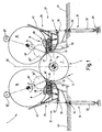
- Figure 1 shows a schematic cross section of a first embodiment of the winding machine according to the invention 1 for a material web 3, the one comprises first support device 5, which acts as a support roller 7 is formed.
- the longitudinal axis 9 of the support roller 7 lies on an imaginary first level E1 extends into the image plane of FIG. 1.
- On both sides of the support roller 7, so left and to the right of level E1 is a second one Support device 11 arranged together with the support roller 7 of the first support device 5 each form a winding bed 13 into the winding tubes 15 can be inserted.
- the winding machine 1 is in the direction of travel of the material web 3 seen - a longitudinal cutting device, not shown preceded the web of material 3 cuts into strips.
- the material strips are fed to the winding machine 1 from below and over part of the driven Support roller 7 of the first support device 5 out.
- the material web strips are on the winding tubes 15 wound into winding rolls, of which in Figure 1 shows only the winding rollers 17 and 19 are.
- the number of in the changing beds 13 aligned winding cores 15 can be the number the material web strip separated from the material web 3 correspond. It is also one Block winding possible, i.e. at least two Material web strips are on a common Winding sleeve wound up after the winding process separated at the joint of the material strips can be.
- the number of winding tubes can also be smaller than the number of material web strips.
- FIG. 4 is a schematic plan view the winding machine 1 according to FIG. 1 can be seen, that in the right of level E1 Changing bed 13 except the winding roll 17 further winding rollers 21 and 23 are wound.
- the winding rolls 17, 21, 23 are at a distance arranged to each other and have different Spread out, with the winding rollers 17 and 23 here are the same width. Of course they can Winding rolls 17, 23 in another embodiment have different widths.
- the Winding roller 19 By doing provided on the left side of the E1 changing bed 13, the winding roll 19 and at a distance another winding roll 25 wound up, the Winding roller 19 the space between the in the right changing bed 13 at a distance from each other arranged winding rollers 17, 21 and the winding roller 25 the space between the winding roll 21 and is opposite the winding roll 23. It becomes clear that the led around the support roller 7, alternating strips of material web lying alternately fed to the left and right changing beds 13 become.
- the winding sleeves inserted into the winding beds 13 15 are each during the winding process guided a guide device, not shown.
- the guide device is designed to be displaceable, the diameter increase of the winding roll to compensate as well as the increasing diameter to guide and relieve the winding roll, which becomes more difficult, so that the forces and tensions in the between the first support device 5 and the second support device 11 formed nip can be set to a desired value.
- Farther can each winding roll 17, 19, 21, 25, 23 assigned a center drive, not shown be the of the winding tube with a driving force or a moment applied.
- the winding machine 1 constructed identically on both sides of level E1, level E1 is thus in this embodiment the mirror plane, so that in the following only the facilities to the right of level E1 the winding machine 1 will be explained in more detail.
- the second support device 11 is on a lowering device 27 arranged as essentially trough-shaped longitudinal bar 29 is formed, the spread over the entire width of the Winding machine 1 extends.
- the lowering device An actuator 31 is assigned to 27, which acts as a piston / cylinder unit is formed and a cylinder 33 and one connected to a piston 34 Piston rod 35 has.
- the cylinder 33 is like indicated in Figure 1 - at one end with a part the winding machine 1 fixedly connected and around a Axis 37, which is substantially parallel to Longitudinal axis 9 of the support roller 7 runs, pivotable stored.
- the piston rod guided in the cylinder 33 35 is pivotable at one end connected to the lowering device 27, which at a Actuation of the actuator 31 by one parallel to the longitudinal axis 9 of the support roller 7 extending axis 39 is pivoted.
- the axis 39 is located below the winding roll 17 and right of the backup roller 7.
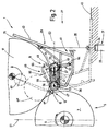
- FIG. 2 shows a section of the winding machine 1 on a greatly enlarged scale, namely the one on the right part of the winding machine 1 lying on the plane E1.
- the same parts are provided with the same reference symbols, so that in this respect based on the description the figure 1 can be referenced.
- the second Support device 11 is a relief module 46 formed and comprises two support rollers 47 and 49, around which an endless support band 51 is guided.
- the support roller 47 of the relief module 46 is over a bearing device also called a bearing block 53 fixedly connected to the lowering device 27 and can be from a drive, not shown, for example, one arranged on the face Motor or an external rotor motor, driven become.
- a Carrier plate 55 which is about the axis of rotation 56 of the Support roller 47 is pivotally mounted, is the other Back-up roller 49 of the relief module 46 in a guide 57 designed as an elongated hole stored.
- a piston / Cylinder unit trained clamping device 59 arranged to adjust the voltage of the Support tape 51 is used. Through the tensioning device 59 the distance of the axis of rotation 61 of the Support roller 49 to the axis of rotation 56 of the support roller 47 and thus the support band tension can be adjusted.
- An actuator 63 is located on the lowering device 27 provided, which is assigned to the relief module 46 and also designed as a piston / cylinder unit is.
- the actuator 63 can also - as the actuator associated with the lowering device 27 31- can be configured as desired, for example one coupled with a mechanical transmission Electric motor or a hydraulic motor that is also referred to as an oil motor.
- the actuator 63 has a cylinder 64 and a guided therein Piston rod 65 on.
- the cylinder 64 is rotatable attached to the lowering device 27 while the piston rod 65 in the region of the axis of rotation 61 of the support roller 49 with the carrier plate 55 connected is.
- the following is the function of the lowering device 27 and that of the second support device 11 of the Winding machine 1 using a single winding roll, namely the winding roll 17, explained in more detail.
- the Lowering device 27 and the second support device 11, that is, the relief module 46 In front the winding of the material web 3 or one of these strips will be the Lowering device 27 and the second support device 11, that is, the relief module 46, in their Starting positions, which are shown in FIGS and 2 are shown with solid lines.
- the lowering device 27 is in this position counterclockwise up to the stop 41 pivoted, whereby the second support device 11 occupies a first functional position.
- the piston rod 65 of the Actuator 63 Before start of the winding process, the piston rod 65 of the Actuator 63 retracted, in this position the piston rod 65 has a dash-dotted line imagined second level E2, on which the Axes of rotation 56, 61 of the support rollers 47, 49 lie, is arranged approximately horizontally, for example.
- the plane 52 can also be easily used as a central roller designated support roller must be employed, include an acute angle with the horizontal and -in Figure 2- fall to the left.
- the Backing roller 47 of the second support device 11 forms together with the support roller 7 of the first support device 5 the changing bed 13 into which the Winding sleeve 15 is inserted.
- Load roller 67 presses at the start of the winding process the winding tube 15 or as it progresses Wind the winding roll 17 with a defined force in the changing bed 13 and until the dead weight of the winding roll 17 is sufficient to achieve a desired line force in the Roll nip between the support roller 7 and the winding roll 17 and the winding roll 17 and the second Adjust support 11.
- the winding roll 17 is short after winding up the free end of the material web 3 on the winding tube 15 (reference number 17 ') and during the winding process (reference number 17 '') indicated by dashed lines.
- the diameter of the winding roll 17 becomes the support roller 49 of the second support device 11 from the actuator 63 about the axis of rotation 56 of the support roller 47 pivoted counterclockwise and so far that from a given diameter Winding roll 17 this one between the Support rollers 47, 49 lying support belt section 69 taken over and during the further winding process is relieved.
- the peripheral area at which the support band section 69 of the second support device 11 on the winding roll 17 applied forces and tensions can by varying the tension of the support band 51 can be set.
- a small perimeter leads to a larger one with the same contact forces Surface pressure.
- the actuator 63 can be a desired support or Relief of the winding roll 17 set and thus the size of the in the winding gap between the winding roll 17 and the Support roller 7 acting the first support device 5 Line force.
- Figure 4 shows a schematic plan view of the Winding machine 1 according to Figure 1 during winding the winding rollers 17, 19, 21, 25, 23. It it becomes clear that the second support device 11 is formed by a number of relief modules 46, which are spaced from each other and each over a relatively narrow, the same extend large width range of the winding machine 1.
- the relief modules 46 are identical to the relief module described with reference to FIG. 2 46 built.
- the maximum width of a Relief module is smaller than the shortest Winding roll.
- “width” is used a longitudinal extension of the relief module, that is, the support band 51 and / or the Back-up rollers 47, 49 in the direction of the longitudinal extent understood the winding rolls.
- the relief modules 46 are all on the not shown in Figure 4 Lowering device arranged. The activated relief modules 46, so the one that has the winding rolls Relieve 17, 19, 21, 25, 23 during the winding process, are shown hatched.
- the other Part of the relief modules in their effective range none of the winding rollers 17, 19, 21, 25, 23 arranged is, as well as the relief modules that immediately border on the edge of a winding roll (relief modules 46 ') or the edge of a winding roll overlap (relief modules 46 '') are deactivated.
- The is in the deactivated state Piston rod 65 of the respective relief module associated actuator 63 in the retracted state. In the deactivated state, the relief modules carry so not to relieve one Winding roll at.
- a relief module is activated or is deactivated, the support band 51 and / or at least one of the support rollers 47, 49 of a drive, not shown, are driven.
- the support band 51 and / or at least one of the support rollers 47, 49 of a drive, not shown are driven.
- Another one Embodiment can also the relief modules 46 ', 46' 'to relieve the respective Winding roll can be activated.
- the relief modules 46 of the second support devices 11 of the winding machine 1 can both together as well as independently activated and be deactivated. It is still possible that the relief modules 46 of the two, left and to the right of the level E1 are arranged second support devices 11 can be controlled together. It will clearly that the relief modules 46 also can be temporally and / or mechanically coupled.
- the support rollers 47 of the relief modules 46, 46 ', 46' 'driven together are, that is, the support rollers 47 of the relief modules are coupled together so that during the entire winding process both for Support of the load-relieving modules as well as the deactivated relief modules are driven.
- the relief modules can be from one Drive, for example an electric motor be, which is the structure of the winding machine 1 can be simplified.
- Another one Each relief module is an embodiment 46 a separate drive assigned.
- the Winding machine 1 is according to the above Rolling up individual webs of a material web can be used. But it is also possible to use the winding machine 1 for winding a single continuous Use material web, for example in Connection with a paper machine.
- the Winding machine 1 is therefore only a winding bed provided in which the winding rolls respectively sleeves lie.
- the winding cores can immediately lie next to each other, so that one of the winding machine upstream longitudinal cutting device Material web strips for example in a so-called block winding to winding rolls be wound up.
- the adjacent winding tubes by at least a winding rod or a Tube practically connected to a winding tube. As a result, the effort to manage the Winding sleeves are simplified.
- Figure 3 shows schematically a section of a another embodiment of the winding machine 1 in Cross-section. Parts that are identical to those in FIGS. 2 and 4 match, have the same reference numerals provided so that in this respect on their description with reference to Figures 1, 2 and 4 can be. The following is intended only for the Differences are discussed in more detail.
- the one in figure 3 is shown by a guided not shown guide device such that the lowering device 27 during a retracting movement the piston rod 35 of the actuator 31 a rotational and a translatory movement performs.
- the rotational movement of the lowering device 27 takes place around an axis that is parallel to the longitudinal axis 9 of the support roller 7 of the first Support device 5 runs. Through the rotation movement the lowering device 27 superimposed
- the translational movement can when swiveling the lowering device 27 reduces the space required and the application of the finished winding roll be further improved.
- the second support device is on the lowering device 27 11 arranged as one by one Rotation axis 73 rotatably mounted relief module 46 is trained.
- the axis of rotation 73 of the relief module 46 lies here between the axes of rotation 56, 61 of the support rollers 47 and 49 and points essentially to the two axes of rotation same distance on.
- the axis of rotation 73 of the relief module 46 too the axis of rotation 56 of the support roller 47 one has a larger or smaller distance than to Axis of rotation 61 of the support roller 49.
- the piston rod 65 of the fixed with the lowering device 27 connected actuator 63 is with their free End in the region of the axis of rotation 56 of the Back-up roller 47 connected to the relief module 46.
- the lowering device is used to wind up a material web 3 27 by extending the piston rod 35 of the actuator 31 in one by Stop 41 pivoted defined end position, the shown in Figure 3 with solid lines is.
- the lowering device 27 connected second support device 11 in the first functional position swiveled.
- the first support device 5 becomes the relief module 46 shown in dashed lines in Figure 3 Position shifted by the piston rod 65 of the Actuator 63 is retracted.
- the winding bed 13 becomes at least one winding tube 15 introduced during the winding of the material web 3 or that of one of the Winding machine 1 upstream slitter separate strips of material from each driven by a center drive and each can be guided by a guide.
- the free end of the material web 3 is on the Winding sleeve 15 wound, the line force in the winding nip between winding roller 17 and Back-up rollers 7, 47 applied by the loading roller 67 becomes.
- the relief module 46 that is Back-up rollers 47, 49 and the support belt 51, of which Actuator 63 clockwise around the axis of rotation 73 rotated, so that between the support rollers 47, 49 lying support band section 69 on the Winding roll 17 abuts and this during the further Winding process flat on a circumferential area supports or relieves.
- Relief module 46 When reached of the end diameter of the winding roll 17 is Relief module 46 in the solid line in FIG Lines shown position arrived.
- Figure 5 shows a schematic plan view of the Winding machine 1 according to FIG. 3. It can be seen that the second support device 11 -like the one based on of Figures 1, 2 and 4 described - by a number is formed by relief modules 46. The to an edge area of the winding rolls directly adjacent or overlapping this Relief modules 46 ', 46' 'are during the Winding process activated, so they are in a position in which the winding roll to be relieved is supported. In an advantageous embodiment it is envisaged that the relief modules 46 ', 46' 'with a lower contact pressure the respective winding roll are pressed so that the load on the edge of the winding roll is reduced can be.
- the size of the contact pressure can depending on the respective coverage or Relief module overlap 46 ', 46' 'selected, preferably set. It is here as in the embodiment according to Figure 4- So possible the relief modules 46 ', 46' 'only with a relatively small contact pressure to press the winding roller so that it only a very small contribution to their support Afford.
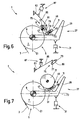
- FIGS 6 and 7 show a functional sequence of a another, shown in schematic cross section Embodiment of the winding machine 1. Same Parts are provided with the same reference symbols, see above in so far as the description of the previous Figures can be referenced.
- the Relief module 46 is as about the axis of rotation 73 rotatable rocker formed in this embodiment no actuator is assigned.
- the relief module 46 is rotated automatically, which will be discussed in more detail below becomes. It is possible that the figures 6 and 7 described second support device 11 formed by a plurality of relief modules 46 is arranged on the lowering device 27 are. The following is purely exemplary assumed that only one relief module 46 is provided is that is essentially the whole Width of the winding machine 1 extends.
- a load device is located above the support devices 5 and 11 75 arranged the two loading rollers 77 and 79 includes the at least a load band 81 is guided.
- the load device 75 is one by one at one end Axis 83 pivotable pivot lever 85 pivotable stored.
- the pivot lever 85 can be of a Piston / cylinder unit indicated drive 87 in and pivoted counterclockwise. As can be seen from Figure 6, when winding the loading device 75, that is, an between the belt section lying the loading rollers 77, 79 89, by pivoting the pivot lever 85 clockwise against the on the Support roller 7 of the first support device 5 Winding roll 17 with a predetermined force pressed. That arranged on the lowering device 27 Relief module 46 is located in the first functional position.
- Winding process becomes the diameter of the winding roll 17 always larger, whereby from a certain roll diameter, for example a diameter of 600 mm, the winding roll 17 from the relief module 46 is supported or relieved (see Figure 7).
- the loading device 75 is now no longer needed and swiveled away as one Control of the force in the nip between the belt section 89 and the winding roller 17 now with the help of the actuator associated with the lowering device 27 31 can be done.
- the winding roll 17 will supported flat during the further winding process, their weight becoming more and more of the relief module 46 is added.
- the lowering device 27 is clockwise pivoted. This will make the relief module 46 shifted to the second functional position, by practically tipping over the axis of rotation 73.
- the tipping of the relief module 46 supports clockwise the deployment of the winding roll 17, the a certain angle of inclination of the support wall 71 compared to the storage space, not shown for the finished winding rolls automatically from the lowering device 27 rolls out.
- winding machine 1 provided that the relief module 46 a separate Actuator is assigned by means of which the size of the contact pressure of the relief module the winding roll and thus its relief set can be. So it is possible that Relief module 46 or one of the Support rollers 47, 49 and the lowering device 27 separately are shiftable from each other. For example it is possible that the relief module 46 an actuator is assigned to the fulcrum the support roller 49 attacks and the relief module 46 about the axis of rotation 73 or the axis of rotation 56 the support roller 47 pivoted. This can do that Relief module 46, for example for takeover the winding roll, pivoted against a stop become.
- the actuator can be deactivated, so it does not Contribution to influencing the winding forces, that is the support of the winding roll.
- the actuator can for example during the winding process Damping of vibrations of the winding roll used become. Due to the separate actuator the relief module 46 into the second functional position be relocated to the Axis of rotation 73 is pivoted. This can Extend the winding roll 17 from the clockwise pivoted lowering device 27 defined be performed.
- a loading device 75 and a second support device 11 comprising Winding station is provided so that on both Sides of the centrally arranged backup roller 7 Rolls can be rolled up.
- Winding sleeves are understood to mean both those have a drum-shaped body as also so-called winding cores, which are made of solid material include existing basic body.
- the Winding cores can - as already described above each held a separate guide device be, so that a defined control of the Each individual winding roll can be wound is. It is also possible that the winding tubes be driven so that an additional possibility given to influence the winding quality is.
- the second support device 11 or the relief module only from a backup roller, support roller or the like can be formed. It is also possible that several at the lowering device Carrier rollers arranged the winding module the relief module form, each relief module an actuator 31 can be assigned.
- the structure the winding machine 1 by the arrangement of the second Support device 11 on the lowering device 27 can be simplified.
- Support band comprehensive relief module a flat relief of the winding roll possible, whereby the winding result can be improved.
Description
Die Erfindung betrifft eine Wickelmaschine für eine Materialbahn, insbesondere Papier- oder Kartonbahn, gemäß Oberbegriff des Anspruchs 1.The invention relates to a winding machine for a Material web, in particular paper or cardboard web, according to the preamble of claim 1.
Wickelmaschinen der hier angesprochenen Art sind
bekannt (DE 35 41 906 C1). Sie dienen der Herstellung
einer Wickelrolle aus einer Materialbahn und
umfassen mindestens zwei Stützeinrichtungen, die
die Wickelrolle während des Aufwickelns abstützen,
wobei eine erste Stützeinrichtung von einer zentralen
Stützwalze und eine zweite Stützeinrichtung von
einer Tragwalze gebildet wird. Die Stützwalze und
die Tragwalze bilden ein Wickelbett, in dem während
des Aufwickelvorgangs die Wickelrolle aufliegt. Die
bekannte Wickelmaschine weist zum Ausbringen der
fertigen Wickelrolle eine Ausstoßvorrichtung und
eine um eine zur Längsachse der Stützwalze parallel
verlaufende Achse verschwenkbare Absenkeinrichtung
auf. Die Wickelrolle wird von der Ausstoßvorrichtung
aus dem Wickelbett herausgedrückt und durch
ein Verschwenken der Absenkeinrichtung ausgebracht.
Besonders nachteilig bei der bekannten Wickelmaschine
ist, daß deren Aufbau aufwendig und somit
kostenintensiv ist. Weiterhin ist deren Platzbedarf
relativ groß, was zusätzliche Kosten verursacht. Are winding machines of the type mentioned here
known (
Aus der US 4 842 209 geht eine Wickelmaschine der hier angesprochene Art hervor, die eine erste Stützeinrichtung mit einer Stützwalze und eine zweite Stützeinrichtung mit zwei Stützwalzen zum Abstützen der Wickelrolle aufweist. Die zweite Stützeinrichtung ist in mehrere Funktionsstellungen verlagerbar, wobei sie in einer ersten Funktionsstellung der Unterstützung des Anwickelvorgangs und in einer zweiten Funktionsstellung der flächigen Unterstützung beim weiteren Wickeln der Wickelrolle dient. Die Wickelmaschine umfaßt ferner eine Absenkeinrichtung zum Ausbringen der Wickelrolle, die um eine zur Längsachse der Stützwalze der ersten Stützeinrichtung im wesentlichen parallel verlaufende Achse schwenkbar ist. Die Stützeinrichtungen und die Absenkeinrichtung sind als voneinander getrennte Baugruppen ausgebildet, die in einem Abstand nebeneinander angeordnet sind. Deren Platzbedarf ist entsprechend groß.A winding machine of US Pat. No. 4,842,209 mentioned here, the first Support device with a support roller and a second support device with two support rollers for Supporting the winding roll has. The second Support device is in several functional positions relocatable, being in a first functional position supporting the start-up process and in a second functional position of the flat Support with further winding of the winding roll serves. The winding machine also includes a lowering device to bring out the winding roll, the around a to the longitudinal axis of the support roller of the first Support device running essentially parallel Axis is pivotable. The support devices and the lowering device are separate from each other Assemblies formed at a distance are arranged side by side. Their space requirements is correspondingly large.
Es ist Aufgabe der Erfindung, eine Wickelmaschine der eingangs genannten Art zu schaffen, die einen geringeren Platzbedarf aufweist.The object of the invention is a winding machine of the kind mentioned at the beginning to create one has less space.
Zur Lösung dieser Aufgabe wird eine Wickelmaschine vorgeschlagen, die die in Anspruch 1 genannten Merkmale aufweist. Dadurch, daß die zweite Stützeinrichtung mindestens zwei Funktionsstellungen einnehmen kann und in einer ersten Funktionsstellung der Unterstützung des Anwickelvorgangs und in einer zweiten Funktionsstellung der flächigen Unterstützung der Wickelrolle während des weiteren Wickelns dient und insbesondere dadurch, daß die zweite Stützeinrichtung an der Absenkeinrichtung an einer weiteren Achse verschwenkbar bzw. verdrehbar gelagert ist und gemeinsam mit der Absenkeinrichtung um die im wesentlichen parallel zur Längsachse einer ersten Stützwalze verlaufende Achse schwenkbar ist, kann ein kompakter und somit raumsparender Aufbau realisiert werden. In der zweiten Funktionsstellung kann die fertige Wickelrolle von der Absenkeinrichtung aus der Wickelmaschine ausgebracht werden. Auf eine separate Ausstoßvorrichtung zum Ausbringen der Wikkelrolle aus dem Wickelbett kann hierbei verzichtet werden, wodurch der Aufbau der Wickelmaschine vereinfacht und gleichzeitig größere Wickelrollendurchmesser realisiert werden können. Die Absenkeinrichtung und die zweite Stützeinrichtung bilden also eine kompakt bauende Einheit, deren Platzbedarf gegenüber bekannten Wickelmaschinen geringer ist.A winding machine is used to solve this task proposed that mentioned in claim 1 Features. In that the second support device at least two functional positions can take and in a first functional position supporting the start-up process and in a second position of the area support the winding roll during the further Serves winding and in particular in that the second support device on the lowering device is pivotally or rotatably mounted on a further axis and together with the lowering device in order to essentially parallel to the longitudinal axis of a first Back-up roller axis is pivotable, can a compact and thus space-saving construction is realized become. In the second functional position the finished winding roll from the lowering device are brought out of the winding machine. On a separate ejection device for ejecting the winding roll can be dispensed with from the changing bed be made, which simplifies the construction of the winding machine and at the same time larger winding roll diameters can be realized. The lowering device and form the second support device So a compact unit, the space required lower than known winding machines is.
Es wird ein Ausführungsbeispiel der Wickelmaschine bevorzugt, das sich dadurch auszeichnet, daß die zweite Stützeinrichtung als Entlastungsmodul ausgebildet ist, das mindestens zwei Stützwalzen umfaßt, um die mindestens ein endloses Stützband herumgeführt wird. Das Entlastungsmodul ermöglicht sowohl eine linienförmige als auch eine flächige Abstützung der Wickelrolle. Die linienförmige Abstützung wird durch Anlegen mindestens einer der Stützwalzen des Entlastungsmoduls an die Wickelrolle realisiert, während die flächige Abstützung beziehungsweise Entlastung durch das Andrücken eines Stützbandabschnitts an die Wickelrolle erfolgt. Durch eine flächige Abstützung werden ein harter Nip und ein Lufteinschluß unter der obersten Wickellage der Wickelrolle, was insbesondere bei empfindlichen Materialbahnen zu Problemen während des Wickelvorgangs führen kann, sicher vermieden.It becomes an embodiment of the winding machine preferred, which is characterized in that the second support device designed as a relief module which comprises at least two backup rolls, around the at least one endless support band becomes. The relief module enables both a linear as well as a flat support the winding roll. The linear support by placing at least one of the back-up rolls of the relief module on the winding roll, while the planar support respectively Relief by pressing a support band section to the winding roll. By a flat support will be a hard nip and an air inclusion under the uppermost layer of the Winding roll, which is particularly useful for sensitive material webs problems during the wrapping process can safely avoided.
Bei einer weiteren Ausführungsform ist vorgesehen, daß dem Entlastungsmodul ein Stellantrieb zugeordnet ist, mittels dessen mindestens eine der Stützwalzen und/oder ein zwischen den Stützwalzen liegender Stützbandabschnitt an die Wickelrolle andrückbar sind/ist. Das gesamte Entlastungsmodul, eine der Stützwalzen oder der Stützbandabschnitt, kann zur Entlastung der Wickelrolle gegenüber der Absenkeinrichtung verlagert werden. Je größer der Durchmesser der Wickelrolle und somit deren Eigengewicht während des Wickelvorgangs wird, um so mehr kann die Wickelrolle vom Entlastungsmodul abgestützt werden, so daß die Kräfte und Spannungen im Wickelspalt definiert beeinflußt werden können. Durch ein Anlegen des zwischen den Stützwalzen liegenden Stützbandabschnitts an den Umfang der Wickelrolle wird ein weicher Nip realisiert; es erfolgt hier eine flächige Entlastung, wodurch die auf die Materialbahn wirkenden Belastungen im Wickelspalt beziehungsweise -bereich zwischen der Wickelrolle und dem Stützbandabschnitt reduziert werden können.In a further embodiment, that an actuator is assigned to the relief module by means of which at least one of the Back-up rolls and / or one between the back-up rolls lying support band section can be pressed against the winding roll are / is. The entire relief module, one of the support rollers or the support belt section, can relieve the winding roll against the Lowering device to be relocated. The bigger the Diameter of the winding roll and thus its own weight during the wrapping process, the more so the winding roller can be supported by the relief module be so that the forces and tensions in the Winding gap can be influenced defined. By applying the lying between the support rollers Support band section to the circumference of the A soft nip is realized; it takes place here a flat relief, which the loads acting on the material web in Winding gap or area between the Winding roll and the support band section reduced can be.
Bei einem besonders bevorzugten Ausführungsbeispiel ist vorgesehen, daß in Abhängigkeit des Wickelrollengewichts der Anteil des Wickelrollengewichts größer wird, der von dem Entlastungsmodul flächig abgestützt wird, während die linienförmige Abstützung der Wickelrolle mittels der ersten Stützeinrichtung geringer wird. Mit anderen Worten: Die flächige Abstützung der Wickelrolle nimmt mit steigendem Wickelrollengewicht zu, während die linienförmige Abstützung in einem bestimmten Maße abnimmt.In a particularly preferred embodiment it is provided that depending on the weight of the winding roll the proportion of the winding roll weight is larger, the area of the relief module is supported while the linear support the winding roll by means of the first support device becomes lower. In other words: the Flat support of the winding roll increases with increasing Wrapping roll weight too, while the linear Support decreases to a certain extent.
Weiterhin wird ein Ausführungsbeispiel der Wickelmaschine bevorzugt, das sich dadurch auszeichnet, daß mindestens eine Stützwalze des Entlastungsmoduls und/oder das Stützband antreibbar sind/ist. Hierdurch können die Stützwalzen und das Stützband auf die Laufgeschwindigkeit der Materialbahn beschleunigt und während der Entlastung der Wickelrolle mit der gleichen Geschwindigkeit wie diese angetrieben werden. Dadurch können die Trägheitsund Reibungskräfte der Stützwalzen und des Stützbandes des Entlastungsmoduls überwunden werden, so daß bei Anlage einer der Stützwalzen an die Wickelrolle eine Beeinflussung der im Wickelspalt wirkenden Linienkraft und bei Anlage des Stützbandabschnitts an der Wickelrolle eine Beeinflussung der an der Wickelrolle wirkenden Umfangskraft verhindert werden können. Somit werden Beschädigungen der Wickelrollenlagen, die zu einem Abriß der Materialbahn führen können, praktisch ausgeschlossen. Es ist aber auch möglich, die Stützwalzen und das Stützband schneller oder langsamer als die Wickelrolle anzutreiben, wodurch im Wickelspalt eine Umfangskraft auf die Wickelrolle aufgebracht wird, die das Wickelergebnis beeinflußt. Mittels der durch die Relativgeschwindigkeit zwischen der Wickelrolle und den Stützwalzen beziehungsweise dem Stützband des Entlastungsmoduls hervorgerufenen und auf den Umfang der Wickelrolle wirkenden Kräfte können die Spannungen im Wickelspalt/-bereich zwischen der zweiten Stützeinrichtung und der Wickelrolle beeinflußt, vorzugsweise eingestellt werden.Furthermore, an embodiment of the winding machine preferred, which is characterized by that at least one backup roller of the relief module and / or the support band can be driven. As a result, the support rollers and the support belt accelerated to the running speed of the material web and while unloading the winding roll at the same speed as this are driven. This can reduce the inertia Frictional forces of the support rollers and the support belt of the relief module are overcome, so that when one of the support rollers abuts the winding roller an influence on those acting in the winding gap Line force and when the support band section is in contact an influence on the winding roll circumferential force acting on the winding roller is prevented can be. This will damage the Winding roll layers that tear the web of material can lead, practically excluded. It but is also possible, the backup rollers and that Support tape faster or slower than the winding roll to drive, whereby a circumferential force in the winding gap is applied to the winding roll, which affects the winding result. By means of the by the relative speed between the Winding roll and the support rollers or the Support band of the relief module evoked and forces acting on the circumference of the winding roll can the tensions in the winding gap / area between the second support device and the winding roll influenced, preferably adjusted.
Bevorzugt wird weiterhin ein Ausführungsbeispiel der Wickelmaschine, bei dem die Schwenkachse der Absenkeinrichtung mit der Längsachse der Stützwalze der ersten Stützeinrichtung zusammenfällt. Die Absenkeinrichtung und die zweite Stützeinrichtung sind also an der gleichen Stelle innerhalb der Wickelmaschine angeordnet beziehungsweise gelagert, so daß der Lageraufwand und somit der Aufbau der Wickelmaschine weiter vereinfacht werden können.An exemplary embodiment is also preferred the winding machine, in which the pivot axis of the Lowering device with the longitudinal axis of the support roller the first support device coincides. The lowering device and the second support are in the same place within the Winding machine arranged or stored, so that the storage effort and thus the structure of the Winding machine can be further simplified.
Schließlich wird ein Ausführungsbeispiel der Wickelmaschine bevorzugt, das sich dadurch auszeichnet, daß der Wickelrolle ein Antrieb, vorzugsweise ein Zentrumsantrieb zugeordnet ist. Die Antriebskraft beziehungsweise das -moment wird also auf die Wickelhülse aufgebracht. Dieser Antrieb erlaubt es, die im Wickelspalt zwischen der Wickelrolle und der Stützwalze der ersten Stützeinrichtung und die im Wickelspalt zwischen der Wickelrolle und der zweiten Stützeinrichtung wirkenden Kräfte und Spannungen sowie das Kernmoment und damit die Spannung im Kern zu beeinflussen beziehungsweise einzustellen, so daß insgesamt das Wickelergebnis verbessert werden kann.Finally, an embodiment of the Preferred winding machine, which is characterized by that the winding roll is a drive, preferably a center drive is assigned. The driving force or the moment applied to the winding tube. This drive allows it that in the winding nip between the winding reel and the support roller of the first support device and that in the winding nip between the winding roll and the second support device acting Forces and tensions as well as the core moment and thus to influence the tension in the core respectively adjust so that overall Winding result can be improved.
Weitere Ausführungsformen ergeben sich aus den übrigen Unteransprüchen.Further embodiments result from the others Dependent claims.
Die Erfindung wird im folgenden anhand der Zeichnung näher erläutert. Es zeigen:
- Figur 1
- einen schematischen Querschnitt einer ersten Ausführungsform der Wickelmaschine, mit einer ersten Ausführungsvariante der zweiten Stützeinrichtung ;
- Figur 2
- einen Ausschnitt der Wickelmaschine gemäß Figur 1 im stark vergrößerten Maßstab;
Figur 3- einen Ausschnitt einer weiteren Ausführungsform der Wickelmaschine, mit einer zweiten Ausführungsvariante der zweiten Stützeinrichtung;
- Figur 4
- eine schematische Draufsicht auf die Wickelmaschine gemäß Figur 1;
Figur 5- eine schematische Draufsicht auf die
Wickelmaschine gemäß
Figur 3 und - Figuren 6 und 7
- einen Ausschnitt einer dritten Ausführungsform der Wickelmaschine, mit einer dritten Ausführungsvariante der zweiten Stützeinrichtung.
- Figure 1
- a schematic cross section of a first embodiment of the winding machine, with a first embodiment of the second support device;
- Figure 2
- a section of the winding machine according to Figure 1 on a greatly enlarged scale;
- Figure 3
- a section of a further embodiment of the winding machine, with a second embodiment of the second support device;
- Figure 4
- a schematic plan view of the winding machine according to Figure 1;
- Figure 5
- a schematic plan view of the winding machine according to Figure 3 and
- Figures 6 and 7
- a section of a third embodiment of the winding machine, with a third embodiment of the second support device.
Figur 1 zeigt einen schematischen Querschnitt einer
ersten Ausführungsform der erfindungsgemäßen Wikkelmaschine
1 für eine Materialbahn 3, die eine
erste Stützeinrichtung 5 umfaßt, die als Stützwalze
7 ausgebildet ist. Die Längsachse 9 der Stützwalze
7 liegt auf einer gedachten ersten Ebene E1, die
sich in die Bildebene der Figur 1 erstreckt. Auf
beiden Seiten der Stützwalze 7, also links und
rechts von der Ebene E1, ist jeweils eine zweite
Stützeinrichtung 11 angeordnet, die zusammen mit
der Stützwalze 7 der ersten Stützeinrichtung 5 jeweils
ein Wickelbett 13 ausbilden, in das Wickelhülsen
15 eingelegt werden.Figure 1 shows a schematic cross section of a
first embodiment of the winding machine according to the invention
1 for a
Der Wickelmaschine 1 ist -in Laufrichtung der Materialbahn
3 gesehen- eine nicht dargestellte Längsschneideeinrichtung
vorgeordnet, die die Materialbahn
3 in Streifen schneidet. Die Materialbahnstreifen
werden der Wickelmaschine 1 von unten zugeführt
und über einen Teilumfang der angetriebenen
Stützwalze 7 der ersten Stützeinrichtung 5 geführt.
Die Materialbahnstreifen werden auf die Wickelhülsen
15 zu Wickelrollen aufgewickelt, von denen in
Figur 1 lediglich die Wickelrollen 17 und 19 dargestellt
sind. Die Anzahl der in den Wickelbetten 13
fluchtend aufgereihten Wickelhülsen 15 kann der Anzahl
der von der Materialbahn 3 abgetrennten Materialbahnstreifen
entsprechen. Es ist auch eine
Blockwicklung möglich, das heißt mindestens zwei
Materialbahnstreifen werden auf eine gemeinsame
Wickelhülse aufgewickelt, die nach dem Wickelvorgang
an der Stoßstelle der Materialstreifen getrennt
werden kann. Die Anzahl der Wickelhülsen
kann also auch kleiner sein als die Anzahl der Materialbahnstreifen.The winding machine 1 is in the direction of travel of the
Aus Figur 4, die eine schematische Draufsicht auf
die Wickelmaschine 1 gemäß Figur 1 zeigt, ist ersichtlich,
daß in dem rechts von der Ebene E1 liegenden
Wickelbett 13 außer der Wickelrolle 17 noch
weitere Wickelrollen 21 und 23 gewickelt werden.
Die Wickelrollen 17, 21, 23 sind in einem Abstand
zueinander angeordnet und weisen unterschiedliche
Breiten auf, wobei die Wickelrollen 17 und 23 hier
gleich breit sind. Selbstverständlich können die
Wickelrollen 17, 23 in einem anderen Ausführungsbeispiel
unterschiedliche Breiten aufweisen. In dem
auf der linken Seite der E1 vorgesehenen Wickelbett
13 werden die Wickelrolle 19 und in einem Abstand
eine weitere Wickelrolle 25 aufgewickelt, wobei die
Wickelrolle 19 dem Zwischenraum zwischen den in dem
rechten Wickelbett 13 in einem Abstand zueinander
angeordneten Wickelrollen 17, 21 und die Wickelrolle
25 dem Raum zwischen der Wickelrolle 21 und
der Wickelrolle 23 gegenüberliegt. Es wird deutlich,
daß die um die Stützwalze 7 herumgeführten,
nebeneinanderliegenden Materialbahnstreifen abwechselnd
dem linken und dem rechten Wickelbett 13 zugeführt
werden. From Figure 4, which is a schematic plan view
the winding machine 1 according to FIG. 1 can be seen,
that in the right of level
Die in die Wickelbetten 13 eingelegten Wickelhülsen
15 werden während des Wickelvorgangs von jeweils
einer nicht dargestellten Führungseinrichtung geführt.
Die Führungseinrichtung ist verlagerbar ausgebildet,
um den Durchmesserzuwachs der Wickelrolle
auszugleichen sowie die mit zunehmendem Durchmesser
schwerer werdende Wickelrolle zu führen und zu entlasten,
so daß die Kräfte und Spannungen in den
zwischen der ersten Stützeinrichtung 5 und der
zweiten Stützeinrichtung 11 gebildeten Wickelspalte
auf einen gewünschten Wert einstellbar sind. Weiterhin
kann jeder Wickelrolle 17, 19, 21, 25, 23
ein nicht dargestellter Zentrumsantrieb zugeordnet
werden, der die Wickelhülse mit einer Antriebskraft
beziehungsweise einem -moment beaufschlagt.The winding sleeves inserted into the winding
Wie aus Figur 1 ersichtlich, ist die Wickelmaschine
1 auf beiden Seiten der Ebene E1 identisch aufgebaut,
die Ebene E1 ist also in diesem Ausführungsbeispiel
die Spiegelebene, so daß im folgenden lediglich
die rechts der Ebene E1 liegenden Einrichtungen
der Wickelmaschine 1 näher erläutert werden.
Die zweite Stützeinrichtung 11 ist an einer Absenkeinrichtung
27 angeordnet, die als im wesentlichen
rinnenförmiger Längsbalken 29 ausgebildet ist, der
sich im wesentlichen über die gesamte Breite der
Wickelmaschine 1 erstreckt. Der Absenkeinrichtung
27 ist ein Stellantrieb 31 zugeordnet, der als Kolben-/Zylindereinheit
ausgebildet ist und einen Zylinder
33 und eine mit einem Kolben 34 verbundene
Kolbenstange 35 aufweist. Der Zylinder 33 ist -wie
in Figur 1 angedeutet- an einem Ende mit einem Teil
der Wickelmaschine 1 ortsfest verbunden und um eine
Achse 37, die im wesentlichen parallel zur
Längsachse 9 der Stützwalze 7 verläuft, schwenkbeweglich
gelagert. Die im Zylinder 33 geführte Kolbenstange
35 ist mit einem Ende schwenkbeweglich
mit der Absenkeinrichtung 27 verbunden, die bei einer
Betätigung des Stellantriebs 31 um eine im wesentlichen
parallel zur Längsachse 9 der Stützwalze
7 verlaufende Achse 39 verschwenkt wird. Die Achse
39 befindet sich unterhalb der Wickelrolle 17 und
rechts der Stützwalze 7.As can be seen from Figure 1, the winding machine
1 constructed identically on both sides of level E1,
level E1 is thus in this embodiment
the mirror plane, so that in the following only
the facilities to the right of level E1
the winding machine 1 will be explained in more detail.
The
Bei einer Ausfahrbewegung der Kolbenstange 35 wird
die Absenkeinrichtung 27 entgegen dem Uhrzeigersinn
um die Achse 39 verschwenkt. Der Schwenkbereich ist
durch einen Anschlag 41 begrenzt. Bei einer Einfahrbewegung
der Kolbenstange 35 in den Zylinder 33
wird die Absenkeinrichtung 27 im Uhrzeigersinn verschwenkt,
bis die Absenkeinrichtung 27 mit einer
Wand 43 an einer Ablagefläche 45 der Wickelmaschine
1 anstößt beziehungsweise auf dieser aufliegt. Um
die Absenkeinrichtung 27 zu verschwenken, kann
grundsätzlich jeder beliebige Stellantrieb 31 eingesetzt
werden, beispielsweise ein mit mechanischen
Übertragungsmitteln gekoppelter Elektromotor oder
dergleichen. Der Aufbau der Absenkeinrichtung 27
und der zweiten Stützeinrichtung 11 werden im folgenden
anhand der Figur 2 näher erläutert.When the
Figur 2 zeigt einen Ausschnitt der Wickelmaschine 1
im stark vergrößerten Maßstab, nämlich den rechts
der Ebene E1 liegenden Teil der Wickelmaschine 1.
Gleiche Teile sind mit gleichen Bezugszeichen versehen,
so daß insofern auf die Beschreibung anhand
der Figur 1 verwiesen werden kann. Die zweite
Stützeinrichtung 11 ist als Entlastungsmodul 46
ausgebildet und umfaßt zwei Stützwalzen 47 und 49,
um die ein endloses Stützband 51 herumgeführt wird.
Die Stützwalze 47 des Entlastungsmoduls 46 ist über
eine auch als Lagerbock bezeichnete Lagereinrichtung
53 ortsfest mit der Absenkeinrichtung 27 verbunden
und kann von einem nicht dargestellten Antrieb,
beispielsweise einem stirnseitig angeordneten
Motor oder einem Außenläufermotor, angetrieben
werden. Im Zusammenhang mit der vorliegenden Erfindung
wird unter "ortsfest" eine Lagerung verstanden,
die eine translatorische Bewegung verhindert
und eine rotatorische Bewegung ermöglicht. An einer
Trägerplatte 55, die um die Rotationsachse 56 der
Stützwalze 47 schwenkbar gelagert ist, ist die andere
Stützwalze 49 des Entlastungsmoduls 46 in
einer als Langloch ausgebildeten Führung 57 verschieblich
gelagert. Zwischen den Stützwalzen 47,
49 ist eine in diesem Ausführungsbeispiel als Kolben-
/Zylindereinheit ausgebildete Spanneinrichtung
59 angeordnet, die zur Einstellung der Spannung des
Stützbandes 51 dient. Durch die Spanneinrichtung 59
kann der Abstand der Rotationsachse 61 der
Stützwalze 49 zur Rotationsachse 56 der Stützwalze
47 und somit die Stützbandspannung eingestellt werden.FIG. 2 shows a section of the winding machine 1
on a greatly enlarged scale, namely the one on the right
part of the winding machine 1 lying on the plane E1.
The same parts are provided with the same reference symbols,
so that in this respect based on the description
the figure 1 can be referenced. The
An der Absenkeinrichtung 27 ist ein Stellantrieb 63
vorgesehen, der dem Entlastungsmodul 46 zugeordnet
und der ebenfalls als Kolben-/Zylindereinheit ausgebildet
ist. Auch der Stellantrieb 63 kann -wie
der der Absenkeinrichtung 27 zugeordnete Stellantrieb
31- beliebig ausgestaltet werden, beispielsweise
ein mit einem mechanischen Getriebe gekoppelter
Elektromotor oder ein hydraulischer Motor, der
auch als Ölmotor bezeichnet wird. Der Stellantrieb
63 weist einen Zylinder 64 und eine darin geführte
Kolbenstange 65 auf. Der Zylinder 64 ist drehbeweglich
an der Absenkeinrichtung 27 angebracht, während
die Kolbenstange 65 im Bereich der Rotationsachse
61 der Stützwalze 49 mit der Trägerplatte 55
verbunden ist. Bei einer Ausfahrbewegung der Kolbenstange
65 werden die Trägerplatte 55 und somit
die Stützwalze 49 entgegen dem Uhrzeigersinn um die
Rotationsachse 56 der Stützwalze 47 verschwenkt,
während bei einer Einfahrbewegung der Kolbenstange
65 ein Verschwenken im Uhrzeigersinn erfolgt. In
Figur 2 ist mit gestrichelten Linien die Position
des Stützbandes 51, der Stützwalze 49 und der Trägerplatte
55 dargestellt, die bei ausgefahrener
Kolbenstange 65 eingenommen wird.An
Im folgenden werden die Funktion der Absenkeinrichtung
27 und die der zweiten Stützeinrichtung 11 der
Wickelmaschine 1 anhand einer einzigen Wickelrolle,
nämlich der Wickelrolle 17, näher erläutert. Vor
dem Aufwickeln der Materialbahn 3 beziehungsweise
eines von dieser abgetrennten Streifens werden die
Absenkeinrichtung 27 und die zweite Stützeinrichtung
11, das heißt das Entlastungsmodul 46, in ihre
Ausgangspositionen verfahren, die in den Figuren 1
und 2 mit durchgezogenen Linien dargestellt sind.
In dieser Position ist die Absenkeinrichtung 27
entgegen dem Uhrzeigersinn bis an den Anschlag 41
verschwenkt, wodurch die zweite Stützeinrichtung 11
eine erste Funktionsstellung einnimmt. Vor Beginn
des Wickelvorgangs wird die Kolbenstange 65 des
Stellantriebs 63 eingefahren, wobei in dieser Stellung
der Kolbenstange 65 eine -strichpunktiert angedeutete-
gedachte zweite Ebene E2, auf der die
Rotationsachsen 56, 61 der Stützwalzen 47, 49 liegen,
beispielsweise etwa horizontal angeordnet ist.
Die Ebene 52 kann auch leicht zu der auch als Zentralwalze
bezeichneten Stützwalze angestellt sein,
also einen spitzen Winkel mit der Horizontalen einschließen
und -in Figur 2- nach links abfallen. Die
Stützwalze 47 der zweiten Stützeinrichtung 11 bildet
zusammen mit der Stützwalze 7 der ersten Stützeinrichtung
5 das Wickelbett 13 aus, in die die
Wickelhülse 15 eingelegt wird.The following is the function of the lowering
Eine in Figur 2 lediglich gestrichelt angedeutete
Belastungswalze 67 drückt zu Beginn des Wickelvorgangs
die Wickelhülse 15 beziehungsweise mit fortschreitendem
Aufwickeln die Wickelrolle 17 mit
einer definierten Kraft in das Wickelbett 13 und
zwar so lange, bis das Eigengewicht der Wickelrolle
17 ausreicht, um eine gewünschte Linienkraft im
Walzennip zwischen der Stützwalze 7 und der Wickelrolle
17 sowie der Wickelrolle 17 und der zweiten
Stützeinrichtung 11 einzustellen.One indicated only by dashed lines in FIG. 2
In den Figuren 1 und 2 ist die Wickelrolle 17 kurz
nach dem Aufwickeln des freien Endes der Materialbahn
3 auf die Wickelhülse 15 (Bezugszeichen 17')
sowie während des Wickelvorgangs (Bezugszeichen
17'') gestrichelt angedeutet. Mit zunehmendem
Durchmesser der Wickelrolle 17 wird die Stützwalze
49 der zweiten Stützeinrichtung 11 von dem Stellantrieb
63 um die Rotationsachse 56 der Stützwalze 47
entgegen dem Uhrzeigersinn verschwenkt und zwar so
weit, daß ab einem vorgegebenen Durchmesser der
Wickelrolle 17 diese von einem zwischen den
Stützwalzen 47, 49 liegenden Stützbandabschnitt 69
übernommen und während des weiteren Wickelvorgangs
entlastet wird. Das heißt, die zuvor an der
Stützwalze 47 anliegende Wickelrolle 17 wird nur
noch von dem über einen Umfangsbereich der Wickelrolle
17 anliegenden Stützbandabschnitt 69 entlastet
beziehungsweise abgestützt. In den Figuren 1
und 2 sind die Stützwalze 49 und das Stützband 51
gestrichelt in der Position angedeutet, in der die
Wickelrolle 17'' von dem Stützbandabschnitt 69 entlastet
wird. Mit zunehmendem Durchmesser der
Wickelrolle 17'' wird die Stützwalze 49 von dem
Stellantrieb 63 im Uhrzeigersinn derart verschwenkt,
daß praktisch nur der Stützbandabschnitt
69 am Umfang der Wickelrolle 17 anliegt und diese
nicht nur auf die Stützwalze 49 aufläuft. Die in
dem Umfangsbereich, an der der Stützbandabschnitt
69 der zweiten Stützeinrichtung 11 an der Wickelrolle
17 anliegt, wirkenden Kräfte und Spannungen
können durch Variation der Spannung des Stützbandes
51 eingestellt werden. Je größer die Stützbandspannung
ist, desto kleiner ist der Umfangsbereich, an
dem der Stützbandabschnitt 69 an der Wickelrolle 17
anliegt und umgekehrt. Ein kleiner Umfangsbereich
führt bei gleichen Anpreßkräften zu einer größeren
Flächenpressung. In Figures 1 and 2, the winding
Bei einem anderen Ausführungsbeispiel ist vorgesehen,
daß zum Anwickeln der Wickelhülse 15 die Kolbenstange
65 des Stellantriebs 63 ausgefahren wird,
so daß das Entlastungsmodul 46 in die in Figur 2
gestrichelt dargestellte Position verfahren wird.
Die Materialbahn 3 wird auf die in das Wickelbett
13 eingelegte Wickelhülse 15 zu der Wickelrolle 17
aufgewickelt. Ab einem definierten Wickelrollendurchmesser
(siehe Wickelrolle 17'' in Figur 2)
läuft die Wickelrolle gegen den Stützbandabschnitt
69 der zweiten Stützeinrichtung 11, so daß die bis
dahin linienförmige Abstützung der Wickelrolle mittels
der zweiten Stützeinrichtung 11 in eine flächige
Abstützung übergeht. Mit zunehmenden Durchmesser
der Wickelrolle 17 wird die Stützwalze 49
der zweiten Stützeinrichtung 11 durch eine Einfahrbewegung
der Kolbenstange 65 des Stellantriebs 63
um die Rotationsachse 56 der Stützwalze 47 kontinuierlich
verschwenkt, bis der End-Durchmesser der
Wickelrolle 17 erreicht wird. Durch den Stellantrieb
63 kann eine gewünschte Abstützung beziehungsweise
Entlastung der Wickelrolle 17 eingestellt
werden und somit die Größe der im Wickelspalt
zwischen der Wickelrolle 17 und der
Stützwalze 7 der ersten Stützeinrichtung 5 wirkenden
Linienkraft.In another embodiment,
that for winding the winding
Nach dem Fertigwickeln der Wickelrolle 17 wird die
Absenkeinrichtung 27 aktiviert, das heißt die Kolbenstange
35 des Stellantriebs 31 fährt in den Zylinder
33 ein, wodurch die Absenkeinrichtung 27 im
Uhrzeigersinn um die Achse 39 verschwenkt wird. Das
Entlastungsmodel 46 beziehungsweise die zweite
Stützeinrichtung 11, die während des Wickelvorgangs
und Fertigstellung der Wickelrolle 17 wieder in die
in Figur 2 mit durchgezogenen Linien dargestellte
Position verschwenkt wird, wird durch das Verschwenken
der Absenkeinrichtung 27 ebenfalls verschwenkt
und zwar in eine zweite Funktionsstellung,
in der die fertige Wickelrolle 17 ausgebracht wird.
Beim Verschwenken der Absenkeinrichtung 27 legt
sich die Wickelrolle 17 an eine parallel zur Wand
43 verlaufende Stützwand 71 der Absenkeinrichtung
27 an. Bei Erreichen einer definierten Position, in
der die Stützwand 71 der Absenkeinrichtung 27 gegenüber
der Ablagefläche 45 der Wickelmaschine 1
einen bestimmten Neigungswinkel aufweist, rollt die
Wickelrolle 17 selbsttätig aus der Absenkeinrichtung
27 heraus, also ohne daß eine Kraft von außen
auf die Wickelrolle 17 aufgebracht werden muß.After the winding of the winding
Figur 4 zeigt eine schematische Draufsicht auf die
Wickelmaschine 1 gemäß Figur 1 während des Aufwickelns
der Wickelrollen 17, 19, 21, 25, 23. Es
wird deutlich, daß die zweite Stützeinrichtung 11
von einer Anzahl Entlastungsmodule 46 gebildet ist,
die in einem Abstand zueinander angeordnet sind und
sich jeweils über einen relativ schmalen, gleich
großen Breitenbereich der Wickelmaschine 1 erstrekken.
Die Entlastungsmodule 46 sind identisch wie
das anhand der Figur 2 beschriebene Entlastungsmodul
46 aufgebaut.Figure 4 shows a schematic plan view of the
Winding machine 1 according to Figure 1 during winding
the winding
In einer vorteilhaften Ausführungsform der Erfindung
ist vorgesehen, daß die maximale Breite eines
Entlastungsmoduls kleiner ist als die kürzeste
Wickelrolle. Unter "Breite" wird in diesem Zusammenhang
eine Längserstreckung des Entlastungsmoduls,
das heißt des Stützbandes 51 und/oder den
Stützwalzen 47, 49 in Richtung der Längserstreckung
der Wickelrollen verstanden. Die Entlastungsmodule
46 sind alle auf der in Figur 4 nicht dargestellten
Absenkeinrichtung angeordnet. Die aktivierten Entlastungsmodule
46, also die, die die Wickelrollen
17, 19, 21, 25, 23 während des Wickelvorgangs entlasten,
sind schraffiert dargestellt. Der andere
Teil der Entlastungsmodule, in deren Wirkbereich
keine der Wickelrollen 17, 19, 21, 25, 23 angeordnet
ist, sowie die Entlastungsmodule, die unmittelbar
an den Rand einer Wickelrolle angrenzen (Entlastungsmodule
46') oder den Rand einer Wickelrolle
überlappen (Entlastungsmodule 46''), sind deaktiviert.
Im deaktivierten Zustand befindet sich die
Kolbenstange 65 des dem jeweiligen Entlastungsmodul
zugeordneten Stellantriebs 63 im eingefahrenen Zustand.
Im deaktivierten Zustand tragen die Entlastungsmodule
also nicht zur Entlastung einer
Wickelrolle bei.In an advantageous embodiment of the invention
it is intended that the maximum width of a
Relief module is smaller than the shortest
Winding roll. In this context, "width" is used
a longitudinal extension of the relief module,
that is, the
Unabhängig davon, ob ein Entlastungsmodul aktiviert
oder deaktiviert ist, kann das Stützband 51
und/oder mindestens eine der Stützwalzen 47, 49 von
einem nicht dargestellten Antrieb angetrieben werden.
Durch die Deaktivierung der im Randbereich
einer Wickelrolle befindlichen Entlastungsmodule
46', 46'' kann eine zu hohe örtliche Beanspruchung
der Wickelrollen vermieden werden. Bei einem anderen
Ausführungsbeispiel können auch die Entlastungsmodule
46', 46'' zur Entlastung der jeweiligen
Wickelrolle aktiviert werden.Regardless of whether a relief module is activated
or is deactivated, the
Die Entlastungsmodule 46 der zweiten Stützeinrichtungen
11 der Wickelmaschine 1 können sowohl gemeinsam
als auch unabhängig voneinander aktiviert
und deaktiviert werden. Es ist weiterhin möglich,
daß die Entlastungsmodule 46 der beiden, links und
rechts der Ebene E1 angeordneten zweiten Stützeinrichtungen
11 gemeinsam gesteuert werden. Es wird
deutlich, daß die Entlastungsmodule 46 also auch
zeitlich und/oder mechanisch gekoppelt werden können.The
Bei einem Ausführungsbeispiel der Wickelmaschine 1
ist vorgesehen, daß die Stützwalzen 47 der Entlastungsmodule
46, 46', 46'' gemeinsam angetrieben
werden, das heißt die Stützwalzen 47 der Entlastungsmodule
sind miteinander gekoppelt, so daß
während des gesamten Wickelvorgangs sowohl die zur
Abstützung der Wickelrolle dienenden Entlastungsmodule
als auch die deaktivierten Entlastungsmodule
angetrieben werden. Durch die Kopplung der Entlastungsmodule
miteinander können diese von einem
Antrieb, beispielsweise einem Elektromotor angetrieben
werden, wodurch der Aufbau der Wickelmaschine
1 vereinfacht werden kann. Bei einem anderen
Ausführungsbeispiel wird jedem Entlastungsmodul
46 ein separater Antrieb zugeordnet. Dabei werden
vorzugsweise alle Entlastungsmodule 46, 46', 46''
so lange angetrieben, bis die Wickelrolle so groß
ist, daß sie nicht mehr an den Stützwalzen 47 der
Entlastungsmodule 46', 46'' anliegt, die während
des weiteren Wickelvorgangs deaktiviert werden,
also nicht der flächigen Abstützung der Wickelrolle
dienen.In one embodiment of the winding machine 1
it is provided that the
Aus allem wird deutlich, daß durch die Anordnung
der zweiten Stützeinrichtung 11 auf der zum Ausbringen
der Wickelrolle beziehungsweise -rollen
dienende Absenkeinrichtung 27 der Aufbau der
Wickelmaschine 1 vereinfacht werden kann. Die
Wickelmaschine 1 ist nach dem oben Gesagten zum
Aufwickeln einzelner Bahnen einer Materialbahn verwendbar.
Es ist aber auch möglich, die Wickelmaschine
1 zum Aufwickeln einer einzelnen durchgehenden
Materialbahn einzusetzen, beispielsweise im
Zusammenhang mit einer Papiermaschine.It is clear from everything that the arrangement
the
Selbstverständlich ist es auch möglich, daß der
ersten Stützeinrichtung 5 lediglich auf einer Seite
eine zweite Stützeinrichtung 11 zugeordnet wird.
Bei einem derartigen Ausführungsbeispiel der
Wickelmaschine 1 ist also lediglich ein Wickelbett
vorgesehen, in dem die Wickelrollen beziehungsweise
-hülsen liegen. Die Wickelhülsen können unmittelbar
aneinanderliegen, so daß von einer der Wickelmaschine
vorgeordneten Längsschneideeinrichtung abgetrennte
Materialbahnstreifen beispielsweise in
einer sogenannten Blockwicklung zu Wickelrollen
aufgewickelt werden. Weiterhin ist es möglich, daß
die aneinanderliegenden Wickelhülsen durch mindestens
eine hindurchgesteckte Wickelstange oder ein
Rohr praktisch zu einer Wickelhülse verbunden werden.
Hierdurch kann der Aufwand zur Führung der
Wickelhülsen vereinfacht werden. Of course, it is also possible that the
Figur 3 zeigt schematisch einen Ausschnitt einer
weiteren Ausführungsform der Wickelmaschine 1 im
Querschnitt. Teile, die mit denen in den Figuren 1,
2 und 4 übereinstimmen, sind mit gleichen Bezugszeichen
versehen, so daß insofern auf deren Beschreibung
anhand der Figuren 1, 2 und 4 verwiesen
werden kann. Im folgenden soll lediglich auf die
Unterschiede näher eingegangen werden. Die in Figur
3 dargestellte Absenkeinrichtung 27 wird von einer
nicht dargestellten Führungseinrichtung derart geführt,
daß die Absenkeinrichtung 27 bei einer Einfahrbewegung
der Kolbenstange 35 des Stellantriebs
31 eine rotatorische und eine translatorische Bewegung
durchführt. Die rotatorische Bewegung der Absenkeinrichtung
27 erfolgt um eine Achse, die parallel
zur Längsachse 9 der Stützwalze 7 der ersten
Stützeinrichtung 5 verläuft. Durch die der Rotationsbewegung
der Absenkeinrichtung 27 überlagerte
Translationsbewegung kann der bei einem Verschwenken
der Absenkeinrichtung 27 benötigte Raum verringert
und das Ausbringen der fertigen Wickelrolle
weiter verbessert werden.Figure 3 shows schematically a section of a
another embodiment of the winding machine 1 in
Cross-section. Parts that are identical to those in FIGS.
2 and 4 match, have the same reference numerals
provided so that in this respect on their description
with reference to Figures 1, 2 and 4
can be. The following is intended only for the
Differences are discussed in more detail. The one in figure
3 is shown by a
guided not shown guide device such
that the lowering
An der Absenkeinrichtung 27 ist die zweite Stützeinrichtung
11 angeordnet, die als ein um eine
Drehachse 73 drehbar gelagertes Entlastungsmodul 46
ausgebildet ist. Die Drehachse 73 des Entlastungsmoduls
46 liegt hier zwischen den Rotationsachsen
56, 61 der Stützwalzen 47 beziehungsweise 49 und
weist zu beiden Rotationsachsen im wesentlichen den
gleichen Abstand auf. Alternativ ist es möglich,
daß die Drehachse 73 des Entlastungsmoduls 46 zu
der Rotationsachse 56 der Stützwalze 47 einen
größeren oder kleineren Abstand aufweist als zur
Rotationsachse 61 der Stützwalze 49. Die Kolbenstange
65 des fest mit der Absenkeinrichtung 27
verbundenen Stellantriebs 63 ist mit ihrem freien
Ende im Bereich der Rotationsachse 56 der
Stützwalze 47 mit dem Entlastungsmodul 46 verbunden.
Bei einer Ausfahrbewegung der Kolbenstange 65
aus dem Zylinder 64 wird das gesamte Entlastungsmodul
46 beziehungsweise die unmittelbar der Entlastung
der Wickelrolle 17 dienenden Teile, nämlich
das Stützband 51 und die Stützwalzen 47, 49, im
Uhrzeigersinn verschwenkt. Bei einer Einfahrbewegung
der Kolbenstange 65 des Stellantriebs 63 erfolgt
eine Drehung des Entlastungsmoduls 46 entgegen
dem Uhrzeigersinn, wobei während der gesamten
Drehung des Entlastungsmoduls 46 die Wickelrolle
flächig abgestützt wird.The second support device is on the lowering
Zum Aufwickeln einer Materialbahn 3 wird die Absenkeinrichtung
27 durch ein Ausfahren der Kolbenstange
35 des Stellantriebs 31 in eine durch den
Anschlag 41 definierte Endposition verschwenkt, die
in Figur 3 mit durchgezogenen Linien dargestellt
ist. Hierdurch wird die mit der Absenkeinrichtung
27 verbundene zweite Stützeinrichtung 11 in die
erste Funktionsstellung verschwenkt. Zur Ausbildung
des Wickelbetts 13 zusammen mit der Stützwalze 7
der ersten Stützeinrichtung 5 wird das Entlastungsmodul
46 in die in Figur 3 gestrichelt dargestellte
Position verlagert, indem die Kolbenstange 65 des
Stellantriebs 63 eingefahren wird. In das zwischen
der Stützwalze 7 und der Stützwalze 47 gebildete
Wickelbett 13 wird mindestens eine Wickelhülse 15
eingebracht, die während des Aufwickelns der Materialbahn
3 beziehungsweise der von einer der
Wickelmaschine 1 vorgeordneten Längsschneideeinrichtung
abgetrennten Materialbahnstreifen von jeweils
einem Zentrumsantrieb angetrieben und jeweils
von einer Führungseinrichtung geführt werden kann.
Das freie Ende der Materialbahn 3 wird auf die
Wickelhülse 15 aufgewickelt, wobei die Linienkraft
im Wickelspalt zwischen Wickelrolle 17 und den
Stützwalzen 7, 47 von der Belastungswalze 67 aufgebracht
wird.The lowering device is used to wind up a
Zur Entlastung der mit zunehmendem Durchmesser
schwerer werdenden Wickelrolle 17 wird ab einem
vorgegebenen, beispielsweise einstellbaren Wickelrollendurchmesser
das Entlastungsmodul 46, also die
Stützwalzen 47, 49 und das Stützband 51, von dem
Stellantrieb 63 im Uhrzeigersinn um die Drehachse
73 verdreht, so daß der zwischen den Stützwalzen
47, 49 liegende Stützbandabschnitt 69 an der
Wickelrolle 17 anliegt und diese während des weiteren
Wickelvorgangs auf einem Umfangsbereich flächig
abstützt beziehungsweise entlastet. Bei Erreichen
des End-Durchmessers der Wickelrolle 17 ist das
Entlastungsmodul 46 in der in Figur 3 mit durchgezogenen
Linien dargestellten Position angelangt.To relieve the increasing diameter
heavier winding
Zum Ausbringen der fertigen Wickelrolle 17 auf die
Ablagefläche 45 der Wickelmaschine 1 wird nun durch
eine Einfahrbewegung der Kolbenstange 35 des Stellantriebs
31 die Absenkeinrichtung 27 im Uhrzeigersinn
verschwenkt, wodurch gleichzeitig die zweite
Stützeinrichtung 11 in die zweite Funktionsstellung
verlagert wird. Durch das Verschwenken wird die
Stützwand 71 der Absenkeinrichtung 27 in Richtung
der Ablagefläche 45 der Wickelmaschine 1 geneigt,
so daß die Wickelrolle 17 ohne Einwirkung von außen
aus der Absenkeinrichtung 27 ausrollt.To deploy the finished winding
Figur 5 zeigt eine schematische Draufsicht auf die
Wickelmaschine 1 gemäß Figur 3. Es ist ersichtlich,
daß die zweite Stützeinrichtung 11 -wie die anhand
der Figuren 1, 2 und 4 beschriebene- von einer Anzahl
von Entlastungsmodulen 46 gebildet wird. Die
an einen Randbereich der Wickelrollen unmittelbar
angrenzenden beziehungsweise diesen überlappenden
Entlastungsmodule 46', 46'' sind während des
Wickelvorgangs aktiviert, sie befinden sich also in
einer Stellung, in der die zu entlastende Wickelrolle
abgestützt wird. Bei einer vorteilhaften Ausführungsform
ist vorgesehen, daß die Entlastungsmodule
46', 46'' mit einer geringeren Anpreßkraft an
die jeweilige Wickelrolle angedrückt werden, so daß
die Belastung der Wickelrollenrandbereiche herabgesetzt
werden kann. Die Größe der Anpreßkraft kann
in Abhängigkeit der jeweiligen Überdeckung beziehungsweise
Überlappung des Entlastungsmoduls
46', 46'' gewählt, vorzugsweise eingestellt werden.
Es ist -hier wie auch bei der Ausführungsform gemäß
Figur 4- also möglich, die Entlastungsmodule
46', 46'' nur mit einer relativ kleinen Anpreßkraft
an die Wickelrolle anzudrücken, damit diese nur
einen sehr geringen Beitrag zu deren Abstützung
leisten. Figure 5 shows a schematic plan view of the
Winding machine 1 according to FIG. 3. It can be seen
that the second support device 11 -like the one based on
of Figures 1, 2 and 4 described - by a number
is formed by
Figuren 6 und 7 zeigen eine Funktionsabfolge einer
weiteren, im schematischen Querschnitt dargestellten
Ausführungsform der Wickelmaschine 1. Gleiche
Teile sind mit gleichen Bezugszeichen versehen, so
daß insofern auf die Beschreibung der vorangegangenen
Figuren verwiesen werden kann. Wie aus den Figuren
6 und 7 ersichtlich, fällt hier die
Schwenkachse der Absenkeinrichtung 27 mit der
Längsachse 9 der Stützwalze 7 der ersten Stützeinrichtung
5 zusammen, wodurch ein besonders einfacher
und platzsparender Aufbau der Wickelmaschine
1 realisiert werden kann. Es ist auch möglich, daß
die Schwenkachse beziehungsweise -achsen der als
Längsbalken 29 ausgebildeten Absenkeinrichtung 27
mit der Längsachse 9 der Stützwalze 7 fluchten. Das
Entlastungsmodul 46 ist als um die Drehachse 73
drehbare Wippe ausgebildet, der in diesem Ausführungsbeispiel
kein Stellantrieb zugeordnet ist.
Eine Drehung des Entlastungsmoduls 46 erfolgt
selbsttätig, worauf im folgenden noch näher eingegangen
wird. Es ist möglich, daß die anhand der Figuren
6 und 7 beschriebene zweite Stützeinrichtung
11 von mehreren Entlastungsmodulen 46 gebildet
wird, die auf der Absenkeinrichtung 27 angeordnet
sind. Rein beispielhaft wird im folgenden davon
ausgegangen, daß nur ein Entlastungsmodul 46 vorgesehen
ist, das sich im wesentlichen über die gesamte
Breite der Wickelmaschine 1 erstreckt.Figures 6 and 7 show a functional sequence of a
another, shown in schematic cross section
Embodiment of the winding machine 1. Same
Parts are provided with the same reference symbols, see above
in so far as the description of the previous
Figures can be referenced. As from the figures
6 and 7 can be seen here
Pivot axis of the lowering
Oberhalb der Stützeinrichtung 5 und 11 ist eine Belastungseinrichtung
75 angeordnet, die zwei Belastungswalzen
77 und 79 umfaßt, um die mindestens
ein Belastungsband 81 geführt wird. Die Belastungseinrichtung
75 ist an einem Ende eines um eine
Achse 83 schwenkbaren Schwenkhebels 85 schwenkbar
gelagert. Der Schwenkhebel 85 kann von einem als
Kolben-/Zylindereinheit angedeuteten Antrieb 87 im
und entgegen dem Uhrzeigersinn verschwenkt werden.
Wie aus Figur 6 ersichtlich, wird beim Anwickeln
die Belastungseinrichtung 75, das heißt ein zwischen
den Belastungswalzen 77, 79 liegender Bandabschnitt
89, durch ein Verschwenken des Schwenkhebels
85 im Uhrzeigersinn gegen die an der
Stützwalze 7 der ersten Stützeinrichtung 5 anliegende
Wickelrolle 17 mit einer vorgegebenen Kraft
gepreßt. Das an der Absenkeinrichtung 27 angeordnete
Entlastungsmodul 46 befindet sich dabei in der
ersten Funktionsstellung. Mit fortschreitendem
Wickelvorgang wird der Durchmesser der Wickelrolle
17 immer größer, wobei ab einem bestimmten Rollendurchmesser,
beispielsweise einem Durchmesser von
600 mm, die Wickelrolle 17 von dem Entlastungsmodul
46 abgestützt beziehungsweise entlastet wird (siehe
Figur 7). Die Belastungseinrichtung 75 wird nun
nicht mehr benötigt und weggeschwenkt, da eine
Steuerung der Kraft im Nip zwischen dem Bandabschnitt
89 und der Wickelrolle 17 jetzt mit Hilfe
des der Absenkeinrichtung 27 zugeordneten Stellantriebs
31 erfolgen kann. Die Wickelrolle 17 wird
während des weiteren Wickelvorgangs flächig abgestützt,
wobei deren Gewicht immer mehr von dem Entlastungsmodul
46 aufgenommen wird.A load device is located above the
Zum Ausbringen der fertigen Wickelrolle 17, die
einen Durchmesser von 1800 mm und größer aufweisen
kann, wird die Absenkeinrichtung 27 im Uhrzeigersinn
verschwenkt. Hierdurch wird das Entlastungsmodul
46 in die zweite Funktionsstellung verlagert,
indem es um die Drehachse 73 quasi abkippt. Das Abkippen
des Entlastungsmodul 46 im Uhrzeigersinn unterstützt
das Ausbringen der Wickelrolle 17, die ab
einem bestimmten Neigungswinkel der Stützwand 71
gegenüber der nicht dargestellten Ablagefläche für
die fertigen Wickelrollen selbsttätig aus der Absenkeinrichtung
27 herausrollt.To bring out the finished winding
Bei einem anderen Ausführungsbeispiel der in den
Figuren 6 und 7 dargestellten Wickelmaschine 1 ist
vorgesehen, daß dem Entlastungsmodul 46 ein separater
Stellantrieb zugeordnet wird, mittels dessen
die Größe der Anpreßkraft des Entlastungsmoduls an
die Wickelrolle und somit deren Entlastung eingestellt
werden kann. Es ist also möglich, daß das
Entlastungsmodul 46 beziehungsweise eine der
Stützwalzen 47, 49 und die Absenkeinrichtung 27 getrennt
voneinander verlagerbar sind. Es ist beispielsweise
möglich, daß dem Entlastungsmodul 46
ein Stellantrieb zugeordnet ist, der am Drehpunkt
der Stützwalze 49 angreift und das Entlastungsmodul
46 um die Drehachse 73 oder die Rotationsachse 56
der Stützwalze 47 verschwenkt. Dadurch kann das
Entlastungmodul 46, beispielsweise zur Übernahme
der Wickelrolle, gegen einen Anschlag verschwenkt
werden. Während des Wickelvorgangs kann der Stellantrieb
deaktiviert werden, er leistet also keinen
Beitrag zur Beeinflussung der Wickelkräfte, also
der Abstützung der Wickelrolle. Der Stellantrieb
kann während des Wickelvorgangs beispeilsweise zur
Dämpfung von Schwingungen der Wickelrolle eingesetzt
werden. Durch den separaten Stellantrieb kann
das Entlastungsmodul 46 in die zweite Funktionsstellung
verlagert werden, indem es um die
Drehachse 73 verschwenkt wird. Hierdurch kann das
Ausbringen der Wickelrolle 17 aus der im Uhrzeigersinn
verschwenkten Absenkeinrichtung 27 definiert
durchgeführt werden.In another embodiment of the in the
Figures 6 and 7 is shown winding machine 1
provided that the relief module 46 a separate
Actuator is assigned by means of which
the size of the contact pressure of the relief module
the winding roll and thus its relief set
can be. So it is possible that
Es ist möglich, daß auf der linken Seite der
Stützwalze 7 eine weitere, eine Belastungseinrichtung
75 und eine zweite Stützeinrichtung 11 umfassende
Wickelstation vorgesehen ist, so daß auf beiden
Seiten der zentral angeordneten Stützwalze 7
Wickelrollen aufgerollt werden können.It is possible that on the left side of the
Back-up
Es bleibt festzuhalten, daß unter dem Begriff "Wickelhülsen" sowohl solche verstanden werden, die einen trommelförmigen Grundkörper aufweisen als auch sogenannte Wickelkerne, die einen aus Vollmaterial bestehenden Grundkörper umfassen. Die Wickelhülsen können -wie oben bereits beschriebenvon jeweils einer separaten Führungseinrichtung gehalten werden, so daß eine definierte Steuerung des Wickelvorgangs jeder einzelnen Wickelrolle möglich ist. Ferner ist es möglich, daß die Wickelhülsen angetrieben werden, so daß eine zusätzliche Möglichkeit zur Beeinflussung der Wickelqualität gegeben ist.It should be noted that under the term "Winding sleeves" are understood to mean both those have a drum-shaped body as also so-called winding cores, which are made of solid material include existing basic body. The Winding cores can - as already described above each held a separate guide device be, so that a defined control of the Each individual winding roll can be wound is. It is also possible that the winding tubes be driven so that an additional possibility given to influence the winding quality is.
Aus allem wird deutlich, daß die zweite Stützeinrichtung
11 beziehungsweise das Entlastungsmodul
lediglich von einer Stützwalze, Tragwalze oder dergleichen
gebildet werden kann. Weiterhin ist möglich,
daß mehrere an der Absenkeinrichtung der
Wickelmaschine angeordnete Tragwalzen das Entlastungsmodul
bilden, wobei jedem Entlastungsmodul
ein Stellantrieb 31 zuordenbar ist.It is clear from everything that the
Zusammenfassend bleibt festzuhalten, daß der Aufbau
der Wickelmaschine 1 durch die Anordnung der zweiten
Stützeinrichtung 11 auf der Absenkeinrichtung
27 vereinfacht werden kann. Durch ein mindestens
zwei Stützwalzen und mindestens ein um diese geführtes
Stützband umfassendes Entlastungsmodul ist
eine flächige Entlastung der Wickelrolle möglich,
wodurch das Wickelergebnis verbessert werden kann.In summary it can be said that the structure
the winding machine 1 by the arrangement of the
Claims (12)
- Winder (1) for a material web (3), in particular a paper- or cardboard web which is rolled onto a winding tube whilst forming at least one winding roll, having at least two support devices (5, 11) supporting the winding roll, a first support device (5) of which is formed by a first support roller (7) and a second support device (11) of which comprises at least one second support roller, the second support device (11) being able to adopt a plurality of operational positions and serving in a first operational position for supporting the winding-on process and in a second operational position for the flat supporting during further winding of the winding roll (17, 21, 23; 19, 25) and having at least one lowering device (27) which serves to withdraw the winding roll and which is pivotable about an axis (39; 9) which extends essentially parallel to the longitudinal axis (9) of the first support roller (7), characterised in that the second support device (11) on the lowering device (27) is mounted pivotably or rotatably on a further axis (56; 73) and is pivotable together with the lowering device (27) about the axis (39; 9).
- Winder according to claim 1, characterised in that the second support device (11) is configured as a load-relieving module (46) which comprises at least two support rollers (47, 49), around which at least one continuous support belt (51) is guided.
- Winder according to claim 2, characterised in that an actuating drive (63) is assigned to the load-relieving module (46), by means of which at least one of the support rollers (47, 49) and/or a support belt portion (69) lying between the support rollers (47, 49) are/is pressable against the winding roll (17, 21, 23; 19, 25).
- Winder according to one of the preceding claims, characterised in that the load-relieving module (46) comprises a tensioning device (59) which can adjust the spacing between the axes of rotation (56, 61) of the support rollers (47, 49).
- Winder according to one of the preceding claims, characterised in that at least one support roller (47, 49) of the load-relieving module (46) and/or the support belt (51) are/is actuatable.
- Winder according to one of the preceding claims, characterised in that the support roller (47) of the load-relieving module (46) is retained by a bearing device connected to the lowering device (27), and in that the support roller (49) of the load-relieving module (46) is pivotable about the axis of rotation (56) of the support roller (47).
- Winder according to one of the claims 1 to 5, characterised in that the load-relieving module (46) is rotatable about an axis, i.e. axis of rotation (73) lying between the support rollers (47, 49).
- Winder according to one of the preceding claims, characterised in that the second support device (11) has at least two load-relieving modules (46) which can be activated and/or deactivated independently of each other or together.
- Winder according to one of the preceding claims, characterised in that the lowering device (27) is configured as a longitudinal beam (29).
- Winder according to one of the preceding claims, characterised in that the pivoting axis (39) of the lowering device (27) extends essentially parallel to the longitudinal axis (9) of the support roller (7) of the first support device (5).
- Winder according to one of the claims 1 to 9, characterised in that the pivoting axis (39) of the lowering device (27) coincides with the longitudinal axis (9) of the support roller (7) of the first support device.
- Winder according to one of the preceding claims, characterised in that a drive, preferably a centre drive, is assigned to the winding roll (17; 19; 21; 25; 23).
Applications Claiming Priority (2)
| Application Number | Priority Date | Filing Date | Title |
|---|---|---|---|
| DE19727012A DE19727012A1 (en) | 1997-06-25 | 1997-06-25 | Winding machine |
| DE19727012 | 1997-06-25 |
Publications (2)
| Publication Number | Publication Date |
|---|---|
| EP0887294A1 EP0887294A1 (en) | 1998-12-30 |
| EP0887294B1 true EP0887294B1 (en) | 2002-09-04 |
Family
ID=7833640
Family Applications (1)
| Application Number | Title | Priority Date | Filing Date |
|---|---|---|---|
| EP98108285A Expired - Lifetime EP0887294B1 (en) | 1997-06-25 | 1998-05-07 | Winder |
Country Status (3)
| Country | Link |
|---|---|
| US (1) | US5938144A (en) |
| EP (1) | EP0887294B1 (en) |
| DE (2) | DE19727012A1 (en) |
Families Citing this family (13)
| Publication number | Priority date | Publication date | Assignee | Title |
|---|---|---|---|---|
| FI101320B1 (en) * | 1997-04-30 | 1998-05-29 | Valmet Corp | Method and plant for damping oscillation in a paper machine or in a paper finishing device |
| DE19803137C1 (en) * | 1998-01-28 | 1999-06-10 | Voith Sulzer Papiertech Patent | Reel for paper rolls |
| US6742873B1 (en) | 2001-04-16 | 2004-06-01 | Silverbrook Research Pty Ltd | Inkjet printhead construction |
| DE19851023B4 (en) * | 1998-11-05 | 2005-11-03 | Stora Enso Publication Paper Ag | Reel winding device |
| FI105800B (en) * | 1999-02-08 | 2000-10-13 | Valmet Corp | Method of winding |
| JP4585136B2 (en) | 2001-03-29 | 2010-11-24 | メッツォペーパージャパン株式会社 | Winding roll presser and long material winding method |
| DE10115862A1 (en) * | 2001-03-30 | 2002-10-17 | Jagenberg Papiertech Gmbh | Winding machine for winding a material web, in particular a paper or cardboard web, into winding rolls |
| FI113960B (en) * | 2001-06-06 | 2004-07-15 | Metso Paper Inc | Method and apparatus for rolling a web |
| US20030141402A1 (en) * | 2002-01-30 | 2003-07-31 | Matthias Schmitt | Aid for starting to wind a belt on a reel |
| DE10308055B3 (en) * | 2003-02-26 | 2004-07-15 | Voith Paper Patent Gmbh | Web winding unit, to wind a paper/cardboard web into a roll, has two carrier rollers for an initial winding bed with a third roller to form a second winding bed as the roll diameter increases |
| US8281633B2 (en) * | 2008-02-21 | 2012-10-09 | Hatch Ltd. | Active transfer apparatus for hot strip mill coilbox |
| FR2953207B1 (en) * | 2009-11-27 | 2011-12-30 | Michelin Rech Tech | DEVICE FOR HANDLING A BAND OF A PRODUCT CONTAINING A GUM AND METHOD FOR PRODUCING A ROLL ON WHICH THE BAND IS WOUND |
| DE102011112032A1 (en) * | 2011-08-31 | 2013-02-28 | Andritz Küsters Gmbh | Process for winding cut fed winding material and double carrier roll |
Family Cites Families (31)
| Publication number | Priority date | Publication date | Assignee | Title |
|---|---|---|---|---|
| US2743065A (en) * | 1952-04-08 | 1956-04-24 | Rol O Matic Corp | Web rolling machine |
| US3098619A (en) * | 1960-12-23 | 1963-07-23 | Beloit Iron Works | Winder drum arrangement |
| FR2082373A5 (en) * | 1970-03-12 | 1971-12-10 | Jager Jeune Nle Ets | |
| US3941055A (en) * | 1972-02-16 | 1976-03-02 | Wilhelm Barenschee | Carrier for flexible printing plates |
| DE2313943A1 (en) * | 1973-03-21 | 1974-09-26 | Monforts Fa A | TWO-ROLLER DOCK |
| DE2808168A1 (en) * | 1978-02-25 | 1979-08-30 | Barenschee Wilhelm | Printing cylinder flexible plate securing system - uses adjustable foot and head blocks secured in recess by screws |
| DE2908294C3 (en) * | 1979-03-03 | 1983-11-10 | J.M. Voith Gmbh, 7920 Heidenheim | Device for winding web-shaped material, e.g. paper |
| DE3243994C2 (en) * | 1982-11-27 | 1986-07-10 | J.M. Voith Gmbh, 7920 Heidenheim | Winding machine for winding a lengthwise split web |
| DE3327972A1 (en) * | 1983-08-03 | 1985-02-14 | Fa. Georg Gernhard, 6000 Frankfurt | Rubber blanket |
| FI74260C (en) * | 1985-11-20 | 1988-01-11 | Valmet Paper Machinery Inc | Reeling device. |
| DE3541906C1 (en) * | 1985-11-27 | 1987-02-26 | Voith Gmbh J M | Winding machine for winding a lengthways divided web |
| FI81551C (en) * | 1987-05-20 | 1990-11-12 | Valmet Paper Machinery Inc | PROCEDURE FOR THE MEASUREMENT OF ROLLING OF BANA. |
| FI81770C (en) * | 1987-05-20 | 1990-12-10 | Valmet Paper Machinery Inc | FOERFARANDE VID STYRNING AV PAPPERS RULLSTOL. |
| FI81768C (en) * | 1987-05-20 | 1990-12-10 | Valmet Paper Machinery Inc | Method and apparatus for rolling paper |
| DE3719093A1 (en) * | 1987-06-06 | 1988-12-22 | Jagenberg Ag | DEVICE FOR REWINDING MATERIALS |
| DE3744961C2 (en) * | 1987-11-05 | 1995-05-18 | Beloit Corp | Roll cutting machine for making smaller rolls |
| DE3832601C1 (en) * | 1988-09-26 | 1989-12-07 | J.M. Voith Gmbh, 7920 Heidenheim, De | Winding machine for web-like material, especially paper |
| US5022597A (en) * | 1989-09-27 | 1991-06-11 | Krantz America, Inc. | Sheet winding apparatus |
| US5275345A (en) * | 1989-11-30 | 1994-01-04 | Werner Stahl | Strip coiler |
| US5405100A (en) * | 1990-09-06 | 1995-04-11 | Cooper Machinery, Inc. | Belt let-off assembly |
| DE4039048C2 (en) * | 1990-12-07 | 1994-06-23 | Reifenhaeuser Masch | Winding device for winding a continuously fed plastic web |
| US5150850A (en) * | 1991-05-10 | 1992-09-29 | Beloit Corporation | Method for winding a traveling web on a belted two drum wound web roll winder |
| DE4219485A1 (en) * | 1992-01-24 | 1993-12-16 | Jagenberg Ag | Machine for winding paper or cardboard web on winding tubes - has transversely adjustable air boxes for each winding line, height swivelable in direction of winding roller |
| DE4204839C2 (en) * | 1992-02-18 | 2003-12-11 | Voith Paper Patent Gmbh | Winding machine for winding paper or cardboard webs |
| FI932674A (en) * | 1992-06-13 | 1993-12-14 | Jagenberg Ag | ROLLER MASK FOR ROLLING AV EN PAPPERS- ELLER CARTON |
| ES2105019T3 (en) * | 1993-08-24 | 1997-10-16 | Beloit Technologies Inc | PROCEDURE AND WINDING DEVICE FOR WINDING A STRIP. |
| FI100467B (en) * | 1994-05-26 | 1997-12-15 | Valmet Corp | Method and apparatus for web rolling |
| ATE175171T1 (en) * | 1995-03-29 | 1999-01-15 | Heinrich Schnell | DEVICE FOR RECEIVING OR TAKEOVER RODLESS WINDING CORE |
| DE19513143C2 (en) * | 1995-04-07 | 1998-02-19 | Voith Sulzer Papiermasch Gmbh | Winding machine for winding a running web, in particular a paper web, into a roll |
| DE19606758C2 (en) * | 1996-02-23 | 1999-11-25 | Voith Sulzer Papiermasch Gmbh | Winding machine |
| DE19606755A1 (en) * | 1996-02-23 | 1997-08-28 | Voith Sulzer Papiermasch Gmbh | Winding machine for winding or unwinding a material web |
-
1997
- 1997-06-25 DE DE19727012A patent/DE19727012A1/en not_active Withdrawn
-
1998
- 1998-05-07 EP EP98108285A patent/EP0887294B1/en not_active Expired - Lifetime
- 1998-05-07 DE DE59805378T patent/DE59805378D1/en not_active Expired - Fee Related
- 1998-06-25 US US09/104,800 patent/US5938144A/en not_active Expired - Fee Related
Also Published As
| Publication number | Publication date |
|---|---|
| DE19727012A1 (en) | 1999-01-07 |
| EP0887294A1 (en) | 1998-12-30 |
| DE59805378D1 (en) | 2002-10-10 |
| US5938144A (en) | 1999-08-17 |
Similar Documents
| Publication | Publication Date | Title |
|---|---|---|
| DE69916444T2 (en) | Winding machine for forming large diameter rolls of sheet material with means for inserting a sleeve | |
| EP0887294B1 (en) | Winder | |
| AT398561B (en) | WRAPPING MACHINE FOR SIMULTANEOUSLY AXLE REWINDING OF THE STRIPS OF A LONGITUDINAL SHEET ON AT LEAST TWO WRAPPING REELS | |
| AT505818B1 (en) | METHOD AND ARRANGEMENT FOR A ROLLING DEVICE FOR A FIBERWORK | |
| EP0855355A2 (en) | Winding machine and method for the continuous winding of a web of material | |
| DE3832601C1 (en) | Winding machine for web-like material, especially paper | |
| AT394704B (en) | DEVICE FOR WRAPPING REELS | |
| DE1574301A1 (en) | Roll-up machine for paper or the like, especially roll cutting and rewinding machine | |
| EP0300220B1 (en) | Winding method for winding material fed without interruption on the several winding cores, as well as two-drum winder | |
| DE3800702C2 (en) | Back-up roll winding device | |
| DE3102894C2 (en) | Device for the separate winding of lengthways divided webs | |
| DE7622890U1 (en) | REEL WINDING DEVICE FOR MULTIPLE SLOTTED, FLEXIBLE STRIPS | |
| EP0916603B1 (en) | Winding machine and method, especially for a slitter | |
| EP1055624B1 (en) | Device for winding a web | |
| EP1108669A2 (en) | Reel winding device, in particular for a reel slitting machine | |
| DE8414845U1 (en) | REEL SCAFFOLDING WITH REEL REPLACEMENT FOR FILM OR TAPE MATERIAL REELS | |
| DE19649354B4 (en) | Winding machine for paper or board webs | |
| EP1454858A1 (en) | Winder | |
| DE4302345A1 (en) | Roller cutting machine for winding of narrow material strips | |
| EP0918033B1 (en) | Winding device and method to take up material webs | |
| EP0933320B1 (en) | Reel winder | |
| DE60011271T2 (en) | METHOD AND DEVICE IN THE PROCESS OF WINDING UP A PAPER | |
| DE60118964T2 (en) | DEVICE AND METHOD FOR WRAPPING TRACKS | |
| DE19748995A1 (en) | Method for continuous reeling of strip of material esp. for paper or cardboard | |
| DE19944295A1 (en) | Rolling up device for paper web producing machine, with beams of each primary arm at specified spacing from drum store |
Legal Events
| Date | Code | Title | Description |
|---|---|---|---|
| PUAI | Public reference made under article 153(3) epc to a published international application that has entered the european phase |
Free format text: ORIGINAL CODE: 0009012 |
|
| AK | Designated contracting states |
Kind code of ref document: A1 Designated state(s): DE FI FR GB IT |
|
| AX | Request for extension of the european patent |
Free format text: AL;LT;LV;MK;RO;SI |
|
| 17P | Request for examination filed |
Effective date: 19990120 |
|
| AKX | Designation fees paid |
Free format text: DE FI FR GB IT |
|
| 17Q | First examination report despatched |
Effective date: 20010102 |
|
| GRAG | Despatch of communication of intention to grant |
Free format text: ORIGINAL CODE: EPIDOS AGRA |
|
| GRAG | Despatch of communication of intention to grant |
Free format text: ORIGINAL CODE: EPIDOS AGRA |
|
| GRAH | Despatch of communication of intention to grant a patent |
Free format text: ORIGINAL CODE: EPIDOS IGRA |
|
| RAP1 | Party data changed (applicant data changed or rights of an application transferred) |
Owner name: VOITH PAPER PATENT GMBH |
|
| GRAH | Despatch of communication of intention to grant a patent |
Free format text: ORIGINAL CODE: EPIDOS IGRA |
|
| GRAA | (expected) grant |
Free format text: ORIGINAL CODE: 0009210 |
|
| AK | Designated contracting states |
Kind code of ref document: B1 Designated state(s): DE FI FR GB IT |
|
| PG25 | Lapsed in a contracting state [announced via postgrant information from national office to epo] |
Ref country code: IT Free format text: LAPSE BECAUSE OF FAILURE TO SUBMIT A TRANSLATION OF THE DESCRIPTION OR TO PAY THE FEE WITHIN THE PRESCRIBED TIME-LIMIT;WARNING: LAPSES OF ITALIAN PATENTS WITH EFFECTIVE DATE BEFORE 2007 MAY HAVE OCCURRED AT ANY TIME BEFORE 2007. THE CORRECT EFFECTIVE DATE MAY BE DIFFERENT FROM THE ONE RECORDED. Effective date: 20020904 |
|
| REG | Reference to a national code |
Ref country code: GB Ref legal event code: FG4D Free format text: NOT ENGLISH |
|
| REF | Corresponds to: |
Ref document number: 59805378 Country of ref document: DE Date of ref document: 20021010 |
|
| GBT | Gb: translation of ep patent filed (gb section 77(6)(a)/1977) |
Effective date: 20021127 |
|
| ET | Fr: translation filed | ||
| PGFP | Annual fee paid to national office [announced via postgrant information from national office to epo] |
Ref country code: GB Payment date: 20030422 Year of fee payment: 6 |
|
| PGFP | Annual fee paid to national office [announced via postgrant information from national office to epo] |
Ref country code: FR Payment date: 20030522 Year of fee payment: 6 |
|
| PLBE | No opposition filed within time limit |
Free format text: ORIGINAL CODE: 0009261 |
|
| STAA | Information on the status of an ep patent application or granted ep patent |
Free format text: STATUS: NO OPPOSITION FILED WITHIN TIME LIMIT |
|
| 26N | No opposition filed |
Effective date: 20030605 |
|
| PG25 | Lapsed in a contracting state [announced via postgrant information from national office to epo] |
Ref country code: GB Free format text: LAPSE BECAUSE OF NON-PAYMENT OF DUE FEES Effective date: 20040507 |
|
| GBPC | Gb: european patent ceased through non-payment of renewal fee |
Effective date: 20040507 |
|
| PG25 | Lapsed in a contracting state [announced via postgrant information from national office to epo] |
Ref country code: FR Free format text: LAPSE BECAUSE OF NON-PAYMENT OF DUE FEES Effective date: 20050131 |
|
| REG | Reference to a national code |
Ref country code: FR Ref legal event code: ST |
|
| PGFP | Annual fee paid to national office [announced via postgrant information from national office to epo] |
Ref country code: FI Payment date: 20070514 Year of fee payment: 10 |
|
| PGFP | Annual fee paid to national office [announced via postgrant information from national office to epo] |
Ref country code: DE Payment date: 20070522 Year of fee payment: 10 |
|
| PG25 | Lapsed in a contracting state [announced via postgrant information from national office to epo] |
Ref country code: FI Free format text: LAPSE BECAUSE OF NON-PAYMENT OF DUE FEES Effective date: 20080507 |
|
| PG25 | Lapsed in a contracting state [announced via postgrant information from national office to epo] |
Ref country code: DE Free format text: LAPSE BECAUSE OF NON-PAYMENT OF DUE FEES Effective date: 20081202 |