EP0887189A2 - Tintenstrahldruckpatronenkörper - Google Patents
Tintenstrahldruckpatronenkörper Download PDFInfo
- Publication number
- EP0887189A2 EP0887189A2 EP98111857A EP98111857A EP0887189A2 EP 0887189 A2 EP0887189 A2 EP 0887189A2 EP 98111857 A EP98111857 A EP 98111857A EP 98111857 A EP98111857 A EP 98111857A EP 0887189 A2 EP0887189 A2 EP 0887189A2
- Authority
- EP
- European Patent Office
- Prior art keywords
- ink
- cartridge body
- opening
- jet printer
- printer cartridge
- Prior art date
- Legal status (The legal status is an assumption and is not a legal conclusion. Google has not performed a legal analysis and makes no representation as to the accuracy of the status listed.)
- Withdrawn
Links
Images


Classifications
-
- B—PERFORMING OPERATIONS; TRANSPORTING
- B41—PRINTING; LINING MACHINES; TYPEWRITERS; STAMPS
- B41J—TYPEWRITERS; SELECTIVE PRINTING MECHANISMS, i.e. MECHANISMS PRINTING OTHERWISE THAN FROM A FORME; CORRECTION OF TYPOGRAPHICAL ERRORS
- B41J2/00—Typewriters or selective printing mechanisms characterised by the printing or marking process for which they are designed
- B41J2/005—Typewriters or selective printing mechanisms characterised by the printing or marking process for which they are designed characterised by bringing liquid or particles selectively into contact with a printing material
- B41J2/01—Ink jet
- B41J2/17—Ink jet characterised by ink handling
- B41J2/175—Ink supply systems ; Circuit parts therefor
- B41J2/17503—Ink cartridges
- B41J2/17556—Means for regulating the pressure in the cartridge
-
- B—PERFORMING OPERATIONS; TRANSPORTING
- B41—PRINTING; LINING MACHINES; TYPEWRITERS; STAMPS
- B41J—TYPEWRITERS; SELECTIVE PRINTING MECHANISMS, i.e. MECHANISMS PRINTING OTHERWISE THAN FROM A FORME; CORRECTION OF TYPOGRAPHICAL ERRORS
- B41J2/00—Typewriters or selective printing mechanisms characterised by the printing or marking process for which they are designed
- B41J2/005—Typewriters or selective printing mechanisms characterised by the printing or marking process for which they are designed characterised by bringing liquid or particles selectively into contact with a printing material
- B41J2/01—Ink jet
- B41J2/17—Ink jet characterised by ink handling
- B41J2/175—Ink supply systems ; Circuit parts therefor
- B41J2/17503—Ink cartridges
- B41J2/17513—Inner structure
-
- B—PERFORMING OPERATIONS; TRANSPORTING
- B41—PRINTING; LINING MACHINES; TYPEWRITERS; STAMPS
- B41J—TYPEWRITERS; SELECTIVE PRINTING MECHANISMS, i.e. MECHANISMS PRINTING OTHERWISE THAN FROM A FORME; CORRECTION OF TYPOGRAPHICAL ERRORS
- B41J2/00—Typewriters or selective printing mechanisms characterised by the printing or marking process for which they are designed
- B41J2/005—Typewriters or selective printing mechanisms characterised by the printing or marking process for which they are designed characterised by bringing liquid or particles selectively into contact with a printing material
- B41J2/01—Ink jet
- B41J2/17—Ink jet characterised by ink handling
- B41J2/175—Ink supply systems ; Circuit parts therefor
- B41J2/17503—Ink cartridges
- B41J2/17559—Cartridge manufacturing
-
- B—PERFORMING OPERATIONS; TRANSPORTING
- B41—PRINTING; LINING MACHINES; TYPEWRITERS; STAMPS
- B41J—TYPEWRITERS; SELECTIVE PRINTING MECHANISMS, i.e. MECHANISMS PRINTING OTHERWISE THAN FROM A FORME; CORRECTION OF TYPOGRAPHICAL ERRORS
- B41J2/00—Typewriters or selective printing mechanisms characterised by the printing or marking process for which they are designed
- B41J2/005—Typewriters or selective printing mechanisms characterised by the printing or marking process for which they are designed characterised by bringing liquid or particles selectively into contact with a printing material
- B41J2/01—Ink jet
- B41J2/17—Ink jet characterised by ink handling
- B41J2/175—Ink supply systems ; Circuit parts therefor
- B41J2/17563—Ink filters
Definitions
- the present invention relates to ink-jet printer pens or cartridges, and more particularly to an ink-jet printer cartridge body having an opening extending from a duct of an ink flow pathway to an outer surface of the ink-jet cartridge body and a sealant plug formed in situ to close the opening.
- Color ink-jet printers employ cartridges having ink reservoirs divided into three distinct chambers, each chamber holding ink of one of three primary colors, for example cyan, magenta and yellow.
- the architecture of such cartridges is more complicated than monochromatic cartridges since ink flow pathways from the three chambers converge into a small region at a printhead.
- the cartridges include a cartridge body which may be molded as a monolithic body of plastic material as disclosed in U.S. Patent No. 5,497,178 of DeFosse et. al. which is assigned to the same assignee as the present application and incorporated herein by reference.
- the rigid plugs disclosed in the DeFosse et. al. and Brandon et. al. patents can cause microscopic flash to be released into the ink flow pathways in the cartridge body. The microscopic flash can then travel to the printhead and result in clogs in ink flow channels within the printhead. To minimize the flash, tight tolerances are required for the plugs, opening dimensions and plug placement within the openings.
- the rigid plugs must be prepared for use by cleaning to remove surface contaminating microscopic flash. All of these requirements add to the cost of the ink-jet cartridges.
- the instant invention is directed to an ink-jet printer cartridge body wherein an opening extending to an outer surface of the cartridge body is closed by a sealant plug formed in situ in the opening and a method for making an ink-jet printer cartridge including at least one sealant plug.
- the cartridge body includes an ink flow pathway which interconnects an ink reservoir chamber to an exit port.
- the opening which extends from a duct of the ink flow pathway of the cartridge body to the outer surface of the body, is closed by a polymeric material sealant plug formed by injecting a polymeric material into the opening.
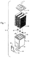
- Fig. 1 illustrates a tri-color ink-jet cartridge 10 or pen comprising a cartridge body 12, a lid 14 and a tape automated bonding (TAB) circuit 20 having a printhead (not shown) attached thereto.
- the cartridge body 12 is formed of a polymeric material, for example, like polysulfone, polyvinyl chloride and, preferably modified polyphenylene oxide which is commercially available from the General Electric Company under the trademark "NORYL SE-1", and has a hollow interior divided into a center and two side ink reservoir chambers 22 by two dividing walls 24.
- Three blocks of foam material 26 are disposed in the reservoir chambers 22 and the chambers are each filled or later refilled with an ink of a different color.
- At the bottom of each of the reservoir chambers 22 is a standpipe 28 and the top of each standpipe is covered with a filter 30 for filtering the ink as it is withdrawn from a chamber.
- the TAB circuit 20 is attached to the bottom and front surface of the cartridge body 12 by two adhesive preforms 32, 34.
- the TAB circuit 20 carries terminals 36 which conduct electrical signals from a printer energy supply circuit (not shown) to a heater chip forming part of the printhead to control ejection of ink through nozzles or orifices in a nozzle plate also forming part of the printhead.
- Inks in the reservoir chambers 22 are drawn from the chambers 22 through filters 30 and the stand pipes 28 during printing.
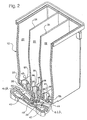
- the cartridge body 12 is formed with three ink flow pathways 38, 41, 45 or passages, as shown by dash-dot lines in FIG. 2, which extend from the reservoir chambers 22 to three exit ports 46, 48 and 50 located within a recess 52 in a bottom surface 54 of the cartridge body 12 as shown in Fig. 3.
- the ink flow pathways 41, 45 include duct portions 42, 40, respectively, see Figs. 2 and 4.
- the printhead comprises print means and is mounted to the surface 54 of the cartridge body 16 so that the three colored inks available at the exit ports 46, 48 and 50 can be selectively ejected through groups of nozzles in the nozzle plate to cause printing in a conventional manner.
- the bottoms of the standpipes 28 are partially closed by sloping bottom surfaces 56, see FIG. 2, so that the openings 44 of approximately semi-circular configuration are formed in the bottoms of the standpipes 28.
- the first ink flow pathway 38 extends from the center ink reservoir chamber 22 to the exit port 46 and includes the center standpipe 28 and a short ink feed tube 39, the ink feed tube 39 extending parallel to the vertical or Z axis, see FIG. 1, of the cartridge 10 between the opening 44 and the exit port 46.
- Two ridges 58 are provided which extend along the entire length of the interior walls of the center standpipe 28 and feed tube 39. These ridges serve to wick ink from the center chamber 22 and also prevent air bubbles from completely blocking the feed tube or standpipe.
- the standpipes 28 for the side reservoir chambers 22 are also provided with ridges 60 and 62, respectively, extending vertically along the entire length of the interior walls of the standpipes. Only one ridge 60 and one ridge 62 is visible in FIG. 2 although the two ridges 60 for the left side standpipe of FIG. 2 are visible in FIG. 4. As shown in FIG. 4, which is a sectional perspective view looking toward the standpipe openings 44, one of the ridges 60 joins with a ridge 64 that extends along the entire length of the top wall 86 of the duct 40.
- the second ink flow pathway 41 extends from the right side ink reservoir chamber 22 of FIG. 2 to the exit port 48.
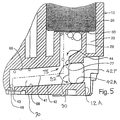
- the second ink flow pathway 41 includes the right-hand standpipe 28, the duct portion 42, and a short feed tube 43, see FIG. 5.
- the duct portion 42 is irregular in shape and is bounded by a top wall 66, a bottom wall 68, and two side walls 70 and 72, see Figs. 4 and 5.
- the side walls 70 and 72 converge to close one end of the duct, the point of convergence being slightly beyond where feed tube 43 joins an opening 73 in the bottom wall.
- the other end of the duct portion 42 extends to an outer surface 12A of the cartridge body 12 through an opening 42A which accommodates removal of a core pin during molding of the cartridge body 12.
- Ink from the right standpipe 28 of FIG. 2 enters the duct 42 through an opening 75 in the top wall 66.
- the standpipe opening 44 is connected with the opening 75 by a short passage 77.
- the duct 42 is generally trapezoidal in cross-section. Side walls 70 and 72 intersect the top wall 66 at acute angles. Since air bubbles assume nearly spherical shapes they will not nest into the acute angles, hence they cannot completely block the flow of ink through the duct 42.
- the third ink flow pathway 45 connects the left ink reservoir chamber 22 to the exit port 50, see FIG. 3.
- the pathway 45 is similar to the pathway 41 and will not be described in detail except to note that it includes a duct portion 40 which extends to an outer surface of the cartridge body 12 through an opening 40A, is provided with side walls 80 and 82 intersecting a top wall 86 at acute angles, a ridge (not shown) on the side wall 80 and a further ridge 64 on the top wall 86.
- the cartridge body 12 may be molded as a monolithic body of plastic material as explained in the referenced DeFosse et al. patent.
- the duct portions 40 and 42 In order to mold the duct portions 40 and 42, it is necessary to provide corresponding openings 40A, 42A in the cartridge body 12 through which core pins of the mold tool may be withdrawn after the cartridge body 12 is formed. After the core pins are withdrawn, the openings 40A, 42A must be closed to prevent ink from leaking from the ink-jet cartridge 10.
- preformed rigid plugs formed of the same material as the cartridge body 12 have been inserted into the openings and ultrasonically welded therein as noted in the "Background of the Invention" portion of the application.
- an improved plug for closing the openings is disclosed in the referenced Brandon et. al. patent.
- the plugs of the Brandon et. al. patent are formed to improve the internal formation of the ink flow pathways to better accommodate movement of air bubbles formed within the ink flow pathways the cartridges.
- the rigid plugs of the prior art can cause microscopic flash to be released into the ink flow pathways 41, 45 which can result in clogs in internal channels in the printhead, thereby preventing ink from being ejected from one or more of the nozzles in the printhead.
- tight tolerances are required for the rigid plugs, the dimensions of the openings and the placement of the rigid plugs within the openings.
- the rigid plugs must be prepared for use by cleaning to remove surface contaminating microscopic flash. All of these requirements add to the production time and cost of manufacturing ink-jet cartridges.
- the sealant plugs are formed by injecting a polymeric material into the openings 40A, 42A.
- the sealant plugs may be made using a thermoset material such as a thermoset adhesive or a thermoplastic material such as a thermoplastic adhesive which is capable of withstanding the temperatures encountered for completing the production of the ink-jet cartridge 10 and is compatible with inks to be used in the cartridge 10.
- Thermoset adhesives which can be used to form the sealant plugs include epoxy resins, polyurethanes, silicone resins and phenolic resins.
- Thermoplastic adhesives which can be used to form the sealant plugs include ethylene-vinyl acetates, ethylene ethylacrylates, polyamides, polyesters, polyurethanes and polystyrenes.
- Other thermoplastics which can be used to form the sealant plugs include high molecular weight materials such as polyolefins, polyesters and polyurethanes. It is currently preferred to use a thixotropic material such as a thermoset urethane adhesive to form the sealant plugs.
- thermoset urethane adhesive is a one-component moisture curing urethane adhesive sold under the trademark "Jet-Weld TE-031” by Minnesota Mining and Manufacturing (3M), although tests have also been made using a two-part epoxy adhesive sold under the trademark "Scotch-Weld DP-11" by 3M.
- the sealant is injected into each of the openings 40A, 42A.
- the sealant may be injected using a commercial adhesive applicator (not shown) such as one which is sold under the "Jet-Weld" trademark by 3M.
- the adhesive applicator may be manually operated or it may be incorporated into a cartridge production apparatus (not shown) such that its operation is machine controlled.
- the volume or shot size of the sealant is selected to seal the opening into which it is injected.
- each of the openings 40A, 42A have a defined volume and, preferably, the shot size of the sealant is selected to substantially equal the volume of the corresponding opening.
- an inner surface 90 of the sealant plug 42P forms a portion of the ink flow pathway 41 and forms a junction portion 92 of the ink flow pathway 41 which junction portion 92 surrounds the plug 42P.
- any microscopic flash which may be present within the openings 40A, 42A is entrapped by injection of the sealant. In this way, no microscopic flash is produced by insertion or formation of the sealant plugs and any such flash which may be present in the openings 40A, 42A of the cartridge body 12 is captured by the sealant plugs.
Applications Claiming Priority (2)
| Application Number | Priority Date | Filing Date | Title |
|---|---|---|---|
| US88290097A | 1997-06-26 | 1997-06-26 | |
| US882900 | 1997-06-26 |
Publications (2)
| Publication Number | Publication Date |
|---|---|
| EP0887189A2 true EP0887189A2 (de) | 1998-12-30 |
| EP0887189A3 EP0887189A3 (de) | 2000-02-02 |
Family
ID=25381568
Family Applications (1)
| Application Number | Title | Priority Date | Filing Date |
|---|---|---|---|
| EP98111857A Withdrawn EP0887189A3 (de) | 1997-06-26 | 1998-06-26 | Tintenstrahldruckpatronenkörper |
Country Status (3)
| Country | Link |
|---|---|
| EP (1) | EP0887189A3 (de) |
| JP (1) | JPH1120195A (de) |
| KR (1) | KR19990007209A (de) |
Cited By (1)
| Publication number | Priority date | Publication date | Assignee | Title |
|---|---|---|---|---|
| WO2006091600A2 (en) * | 2005-02-24 | 2006-08-31 | Hewlett-Packard Development Company, L.P. | Fluid supply system |
Families Citing this family (3)
| Publication number | Priority date | Publication date | Assignee | Title |
|---|---|---|---|---|
| KR100512987B1 (ko) * | 2003-01-16 | 2005-09-07 | 삼성전자주식회사 | 잉크카트리지 |
| KR100571776B1 (ko) * | 2004-02-06 | 2006-04-18 | 삼성전자주식회사 | 잉크카트리지 |
| EP2265683A4 (de) * | 2008-04-18 | 2014-03-26 | Hewlett Packard Development Co | Klebeband zur verwendung mit einem polymersubstrat |
Citations (2)
| Publication number | Priority date | Publication date | Assignee | Title |
|---|---|---|---|---|
| US5497178A (en) | 1993-12-10 | 1996-03-05 | Lexmark International, Inc. | Multicolor liquid ink jet print head |
| US5576750A (en) | 1994-10-11 | 1996-11-19 | Lexmark International, Inc. | Reliable connecting pathways for a three-color ink-jet cartridge |
Family Cites Families (3)
| Publication number | Priority date | Publication date | Assignee | Title |
|---|---|---|---|---|
| EP0419193B1 (de) * | 1989-09-18 | 1996-12-11 | Canon Kabushiki Kaisha | Tintenstrahlgerät |
| CA2136514C (en) * | 1993-11-26 | 2000-01-11 | Masashi Kitani | An ink jet recording head, an ink jet unit and an ink jet apparatus using said recording head |
| JPH07171958A (ja) * | 1993-12-17 | 1995-07-11 | Fuji Xerox Co Ltd | インクジェット記録ヘッド及びその組立方法 |
-
1998
- 1998-06-22 KR KR1019980023430A patent/KR19990007209A/ko not_active Application Discontinuation
- 1998-06-26 EP EP98111857A patent/EP0887189A3/de not_active Withdrawn
- 1998-06-26 JP JP19665198A patent/JPH1120195A/ja not_active Withdrawn
Patent Citations (2)
| Publication number | Priority date | Publication date | Assignee | Title |
|---|---|---|---|---|
| US5497178A (en) | 1993-12-10 | 1996-03-05 | Lexmark International, Inc. | Multicolor liquid ink jet print head |
| US5576750A (en) | 1994-10-11 | 1996-11-19 | Lexmark International, Inc. | Reliable connecting pathways for a three-color ink-jet cartridge |
Cited By (4)
| Publication number | Priority date | Publication date | Assignee | Title |
|---|---|---|---|---|
| WO2006091600A2 (en) * | 2005-02-24 | 2006-08-31 | Hewlett-Packard Development Company, L.P. | Fluid supply system |
| WO2006091600A3 (en) * | 2005-02-24 | 2007-05-31 | Hewlett Packard Development Co | Fluid supply system |
| US7575309B2 (en) | 2005-02-24 | 2009-08-18 | Hewlett-Packard Development Company, L.P. | Fluid supply system |
| US8182076B2 (en) | 2005-02-24 | 2012-05-22 | Hewlett-Packard Development Company, L.P. | Fluid supply system |
Also Published As
| Publication number | Publication date |
|---|---|
| KR19990007209A (ko) | 1999-01-25 |
| EP0887189A3 (de) | 2000-02-02 |
| JPH1120195A (ja) | 1999-01-26 |
Similar Documents
| Publication | Publication Date | Title |
|---|---|---|
| US5497178A (en) | Multicolor liquid ink jet print head | |
| US6331054B1 (en) | Unitary one-piece body structure for ink-jet cartridge | |
| US5831653A (en) | Ink jet print head cartridge | |
| US5621446A (en) | Method of filling an ink container | |
| KR100710975B1 (ko) | 잉크젯 프린터 카트리지 및 그 제조방법 | |
| US9139011B2 (en) | Tank unit and liquid ejecting system having tank unit | |
| US20050185037A1 (en) | Method for making multi-color ink reservoirs for ink jet printers | |
| EP2043869B1 (de) | Druckerpatrone | |
| US5821964A (en) | Cartridge for supplying liquid to a print head | |
| EP0887189A2 (de) | Tintenstrahldruckpatronenkörper | |
| KR100571776B1 (ko) | 잉크카트리지 | |
| EP1024005B1 (de) | Tintenstrahldruckkopf und Verfahren zur Herstellung | |
| EP2170615B1 (de) | Farbdruckpatrone | |
| US6003983A (en) | Contaminant cleaned inkjet cartridge manufacture | |
| US8029118B2 (en) | Ink jet print cartridge with independent adjacent sealing plugs | |
| KR100503082B1 (ko) | 잉크젯 프린터용 잉크 카트리지 | |
| CN1152782C (zh) | 设有气泡储存室的墨水盒及其制作方法 | |
| KR20060020052A (ko) | 잉크젯 카트리지 및 그 제조방법 |
Legal Events
| Date | Code | Title | Description |
|---|---|---|---|
| PUAI | Public reference made under article 153(3) epc to a published international application that has entered the european phase |
Free format text: ORIGINAL CODE: 0009012 |
|
| AK | Designated contracting states |
Kind code of ref document: A2 Designated state(s): AT BE CH CY DE DK ES FI FR GB GR IE IT LI LU MC NL PT SE |
|
| AX | Request for extension of the european patent |
Free format text: AL;LT;LV;MK;RO;SI |
|
| PUAL | Search report despatched |
Free format text: ORIGINAL CODE: 0009013 |
|
| AK | Designated contracting states |
Kind code of ref document: A3 Designated state(s): AT BE CH CY DE DK ES FI FR GB GR IE IT LI LU MC NL PT SE |
|
| AX | Request for extension of the european patent |
Free format text: AL;LT;LV;MK;RO;SI |
|
| STAA | Information on the status of an ep patent application or granted ep patent |
Free format text: STATUS: THE APPLICATION HAS BEEN WITHDRAWN |
|
| 18W | Application withdrawn |
Withdrawal date: 20000125 |