EP0886750B1 - A cooling device - Google Patents
A cooling device Download PDFInfo
- Publication number
- EP0886750B1 EP0886750B1 EP97915656A EP97915656A EP0886750B1 EP 0886750 B1 EP0886750 B1 EP 0886750B1 EP 97915656 A EP97915656 A EP 97915656A EP 97915656 A EP97915656 A EP 97915656A EP 0886750 B1 EP0886750 B1 EP 0886750B1
- Authority
- EP
- European Patent Office
- Prior art keywords
- chilling
- trough
- container
- heat transfer
- transfer medium
- Prior art date
- Legal status (The legal status is an assumption and is not a legal conclusion. Google has not performed a legal analysis and makes no representation as to the accuracy of the status listed.)
- Expired - Lifetime
Links
Images


Classifications
-
- F—MECHANICAL ENGINEERING; LIGHTING; HEATING; WEAPONS; BLASTING
- F25—REFRIGERATION OR COOLING; COMBINED HEATING AND REFRIGERATION SYSTEMS; HEAT PUMP SYSTEMS; MANUFACTURE OR STORAGE OF ICE; LIQUEFACTION SOLIDIFICATION OF GASES
- F25D—REFRIGERATORS; COLD ROOMS; ICE-BOXES; COOLING OR FREEZING APPARATUS NOT OTHERWISE PROVIDED FOR
- F25D17/00—Arrangements for circulating cooling fluids; Arrangements for circulating gas, e.g. air, within refrigerated spaces
- F25D17/02—Arrangements for circulating cooling fluids; Arrangements for circulating gas, e.g. air, within refrigerated spaces for circulating liquids, e.g. brine
-
- F—MECHANICAL ENGINEERING; LIGHTING; HEATING; WEAPONS; BLASTING
- F25—REFRIGERATION OR COOLING; COMBINED HEATING AND REFRIGERATION SYSTEMS; HEAT PUMP SYSTEMS; MANUFACTURE OR STORAGE OF ICE; LIQUEFACTION SOLIDIFICATION OF GASES
- F25D—REFRIGERATORS; COLD ROOMS; ICE-BOXES; COOLING OR FREEZING APPARATUS NOT OTHERWISE PROVIDED FOR
- F25D31/00—Other cooling or freezing apparatus
- F25D31/006—Other cooling or freezing apparatus specially adapted for cooling receptacles, e.g. tanks
- F25D31/007—Bottles or cans
-
- F—MECHANICAL ENGINEERING; LIGHTING; HEATING; WEAPONS; BLASTING
- F25—REFRIGERATION OR COOLING; COMBINED HEATING AND REFRIGERATION SYSTEMS; HEAT PUMP SYSTEMS; MANUFACTURE OR STORAGE OF ICE; LIQUEFACTION SOLIDIFICATION OF GASES
- F25D—REFRIGERATORS; COLD ROOMS; ICE-BOXES; COOLING OR FREEZING APPARATUS NOT OTHERWISE PROVIDED FOR
- F25D2331/00—Details or arrangements of other cooling or freezing apparatus not provided for in other groups of this subclass
- F25D2331/80—Type of cooled receptacles
- F25D2331/803—Bottles
-
- F—MECHANICAL ENGINEERING; LIGHTING; HEATING; WEAPONS; BLASTING
- F25—REFRIGERATION OR COOLING; COMBINED HEATING AND REFRIGERATION SYSTEMS; HEAT PUMP SYSTEMS; MANUFACTURE OR STORAGE OF ICE; LIQUEFACTION SOLIDIFICATION OF GASES
- F25D—REFRIGERATORS; COLD ROOMS; ICE-BOXES; COOLING OR FREEZING APPARATUS NOT OTHERWISE PROVIDED FOR
- F25D2700/00—Means for sensing or measuring; Sensors therefor
- F25D2700/02—Sensors detecting door opening
-
- F—MECHANICAL ENGINEERING; LIGHTING; HEATING; WEAPONS; BLASTING
- F25—REFRIGERATION OR COOLING; COMBINED HEATING AND REFRIGERATION SYSTEMS; HEAT PUMP SYSTEMS; MANUFACTURE OR STORAGE OF ICE; LIQUEFACTION SOLIDIFICATION OF GASES
- F25D—REFRIGERATORS; COLD ROOMS; ICE-BOXES; COOLING OR FREEZING APPARATUS NOT OTHERWISE PROVIDED FOR
- F25D2700/00—Means for sensing or measuring; Sensors therefor
- F25D2700/06—Sensors detecting the presence of a product
Definitions
- Refrigerated cabinets are provided for cooling wines and for maintaining the wines at a desired chill temperature, typically, white wine and rosé wines to approximately 5°C.
- a desired chill temperature typically, white wine and rosé wines to approximately 5°C.
- the interior of such cabinets is illuminated and the cabinets are provided with glass doors for permitting visual inspection of the wines therein.
- Such cabinets in general, tend to be relatively large and are free-standing, in other words, are suitable for standing on a floor or the like. They are also relatively high, typically of height of approximately six feet. While such refrigerated cabinets do chill wines to the desired chill temperature, and maintain the wines at the desired chill temperature, nonetheless, they suffer from a number of disadvantages.
- refrigerated cabinets tend to be relatively unattractive, and are unsightly when located in the dining area of a restaurant. Since, in general, in restaurants, particularly relatively small restaurants, space is at a premium, the only available space in many instances for such cabinets is in the dining area.
- a level control means is provided for controlling the level of the heat transfer medium in the chilling trough.
- the level control means is provided for controlling the level of the heat transfer medium in the chilling trough so that the container is submerged in the heat transfer medium during cooling thereof.
- the level control means comprises an outlet weir over which heat transfer medium flows from the chilling trough.
- a return means is provided for returning heat transfer medium from the chilling trough to the refrigerating means.
- the return means comprises a return pipe located for receiving heat transfer medium from the level control means, and terminating adjacent the refrigerating means for returning the heat transfer medium to the refrigerating means.
- the drain means comprises the inlet port, the inlet port being located adjacent the lowest point of the chilling trough for draining the heat transfer medium therefrom.
- the circulating means facilitates draining of the heat transfer medium therethrough from the chilling trough to the refrigerating means.
- the circulating means is adapted for accommodating draining of the heat transfer medium from the chilling trough to the refrigerating means when the circulating means is deactivated.
- the first sensor is mounted externally of the chilling trough, and the plunger of the first sensor extends into the chilling trough for engaging the container when located in the chilling trough.
- the first sensor is mounted on the lid, and the plunger extends into the hollow interior region of the chilling trough when the lid is in the closed position for engaging the container when placed in the chilling trough.
- the timing means times a second predetermined period of time from the end of the first predetermined period of time
- the control means is responsive to the timing means having timed the second predetermined period of time for activating the circulating means for circulating the heat transfer medium in the event that the container has not been removed from the chilling trough after the end of the first predetermined period of time for maintaining the container at the desired temperature
- timing means times a third predetermined period of time during which the circulating means is operated from the end of the second predetermined period of time for maintaining the temperature of the container at the desired temperature.
- the timing means times further second predetermined periods of time at the end of each third period of time.
- the second predetermined period of time is in the range of 3 minutes to 5 minutes. Preferably, the second predetermined period of time is approximately 4 minutes.
- the first predetermined period of time is in the range of 3 minutes to 5 minutes. Preferably, the first predetermined period of time is approximately 4 minutes.
- the timing means is incorporated in the control means.
- the heat transfer medium comprises an aqueous solution of propylene glycol.
- a means for moving the container within the chilling trough is provided for causing circulation of the contents of the container within the container for improving the heat transfer efficiency between the heat transfer medium and the contents of the container.
- the means for moving the container is adapted for rotating the container about a longitudinally extending central axis of the container.
- the means for moving the container comprises a gripping means located in the chilling trough for gripping the container, and a drive means for driving the gripping means is provided.
- the gripping means is adapted for gripping the container adjacent an axial end thereof, and the gripping means is rotatable by the drive means for rotating the container about its longitudinally extending central axis.
- a common return means is provided for returning the heat transfer medium from the respective chilling troughs to the refrigerating means.
- a heating compartment for heating a container is provided, and a second heat transfer medium transfers waste heat from the refrigerating means to the heating compartment for heating the container therein.
- a second flow means is provided for accommodating the second heat transfer medium from the refrigerating means to each heating trough.
- a level control means is provided for controlling the level of second heat transfer medium in each heating trough.
- a common return means is provided for returning the second heat transfer medium from one or more of the level control means of the respective heating troughs to the second reservoir.
- control means times first, second and third predetermined periods of time for operating the second circulating means of the respective heating troughs in similar fashion as the first, second and third predetermined periods of time are timed in respect of the chilling troughs.
- a plurality of flow means namely, four flow pipes 23, one for each chilling trough 8 connect the respective chilling troughs 8 independently of each other to the reservoir 20 for receiving heat transfer medium therefrom.
- the flow pipes 23 are connected to respective inlet ports 25 of the chilling troughs 8.
- a common return means namely, a common return pipe 27 returns the heat transfer medium from the respective chilling troughs 8 to the reservoir 20.
- a level control comprising an outlet weir 28 is provided in a rear axial end wall 29 of each chilling trough 8 over which heat transfer medium flows from the respective chilling troughs 8 for maintaining the level of heat transfer medium in the chilling troughs 8 at a predetermined level, which is above a wine bottle 2 when the wine bottle 2 is lying on its side in the chilling trough 8.
- each outlet weir 28 maintains the level of heat transfer medium in its corresponding chilling trough 8 so that a wine bottle 2 placed in the chilling trough 8 is completely submerged in the heat transfer medium.
- the inlet ports 25 to the respective chilling troughs 8 are located at the lowest point of the hollow interior region 10 of each chilling trough 8 for facilitating draining of the respective chilling troughs 8 through the corresponding inlet port 25.
- the circulating pumps 34 are of the type which when deactivated permit return flow of heat transfer medium therethrough to the reservoir 20.
- a drain means is provided for draining the heat transfer medium from each chilling trough 8 when the corresponding circulating pump 34 has been deactivated.
- a first detecting means for detecting the presence of a wine bottle 2 in the respective chilling troughs 8 comprises four first sensors 38, namely four plunger type operated micro-switches, one for each chilling trough 8.
- the respective first sensors 38 are located on the respective lids 16 and plungers 39 of the first sensors 38 extend into the hollow interior regions 10 of the chilling troughs 8 when the corresponding lids 16 are in the closed position for engaging a wine bottle 2 in the chilling troughs 8.
- a second detecting means for detecting when the lids 16 of the respective chilling troughs 8 are in the closed position comprises four second sensors 40, namely, plunger type operated micro-switches, one being provided for each chilling trough 8.
- the first predetermined period of time timed by the timer 43 is approximately four minutes.
- the second predetermined period of time timed by the timer 43 is approximately four minutes, and the third predetermined period of time is approximately thirty seconds. It has been found that by circulating the heat transfer medium at a temperature of approximately -20°C for four minutes at a flow rate of approximately 1,300ml per minute is sufficient for reducing the temperature of a wine bottle, and needless to say, the contents thereof from room temperature to a desired chill temperature, which typically, is approximately 5°C.
- the timer 43 commences to time the second predetermined period of time also of four minutes. At the end of the second predetermined period of time should the wine bottle 2 not have been removed from the chilling trough 8, the timer 43 commences to time a third period of time of approximately thirty seconds, and the control circuit 35 reactivates the relevant circulating pump 34 for again circulating heat transfer medium through the chilling trough 8 continuously for the duration of the third predetermined period of time for returning and maintaining the temperature of the wine and the wine bottle 2 at the desired chill temperature of approximately 3°C. The timer 43 continues to alternatively and sequentially time second and third predetermined periods of time until the wine bottle 2 has been removed from the chilling trough 8. The presence or otherwise of a wine bottle 2 in a chilling trough 8 during the second and third periods of time is determined by the control circuit 35 from the status of the first sensor 38 of that chilling trough 8.
- Fig. 7 there is illustrated a portion of a cooling device according to another embodiment of the invention, which is indicated generally by the reference numeral 60.
- the cooling device 60 is substantially similar to the cooling device 1, and similar components are identified by the same reference numerals.
- Four chilling troughs 8 are provided in the cooling device 60.
- the main difference between the cooling device 60 and the cooling device 1 is that a means for moving the wine bottle 2 within each chilling trough 6 is provided for causing circulation of the wine within the wine bottle 2 for facilitating heat transfer between the wine in the wine bottle 2 and the heat transfer medium.
- the means for moving the wine bottle 2 rotates the wine bottle about its longitudinally extending central axis, and comprises a gripping means which is provided by a cup shaped grip 62 for engaging the wine bottle 2 adjacent its end.
- the grip 62 is carried on a shaft 63 which is rotatable in bearings (not shown) in the rear end wall 29 and an end wall 65 which are formed in the top plate 9.
- a drive means namely, an electrically powered motor 66 is located and mounted in a sub-housing (not shown) which extends from the rear of the housing 3 for driving the shaft 63 for in turn rotating the grip 62.
- a wine bottle may be rotated by the grip 62 at rotational speeds in the range of 20 revs per minute to 40 revs per minute, and preferably, speeds in the range of 28 revs per minute to 32 revs per minute. Ideally, the rotational speed of each grip 62 should be maintained constant.
- FIG. 8 there is illustrated a diagrammatic view of a portion of a cooling device according to another embodiment of the invention which is indicated generally by the reference numeral 70.
- the cooling device 70 is substantially similar to the cooling device 1, and similar components are identified by the same reference numerals.
- the main difference between the cooling device 70 and the cooling device 1 is that as well as having four chilling troughs 8 for cooling bottles 2 of wine, the cooling device 1 also comprises two heating troughs 71 for raising the temperature of respective containers, in this case, bottles 2 of red wine to a desired temperature.
- only one chilling trough 8 and one heating trough 71 are illustrated.
- Each heating trough 71 is identical to the chilling troughs 8, and the chilling and heating troughs 8 and 71 are arranged side by side with their respective central axes 12 parallel to each other.
- the two heating troughs 71 are located together, and the four heating troughs 8 are located together.
- Waste heat from the refrigeration circuit 21 is used for heating a second liquid heat transfer medium, which in this case is water for raising the temperature of respective wine bottles 2 in the heating troughs 71.
- a second reservoir 72 is located in the housing 3 within which the water heat transfer medium is heated.
- a collection channel 78 located at the rear end of the two heating troughs 71 collects water from the outlet weirs 77 which is returned through a common return pipe 79 to the reservoir 72.
- Each heating trough 71 is closed by a lid 16 which is hingedly connected by a hinge 17 to the top panel 9 in similar fashion as the lids 16 close the chilling troughs 8.
- a separate lid 16 is provided for each heating trough 71.
- Separate third and fourth sensors 80 and 81 are provided for each heating trough 71 and the sensors 80 and 81 are identical to the first and second sensors 38 and 40. The third and fourth sensors 80 and 81 are read by the control circuit 35.
- An auxiliary heating means in this case an electrically powered immersion heater 85 is located in the water reservoir 72 for boosting the heat of the water therein should this be necessary.
- the immersion heater 85 is operated under the control the control circuit 35 in response to a temperature sensor 86 located in the water reservoir 72 for monitoring the water temperature.
- the circulating pumps 74 are operated independently of each other by the control circuit 35, and in response to the third and fourth sensors 80 and 81 detecting a bottle 2 in one of the heating troughs 71 and the corresponding lid 16 being closed the corresponding circulating pump 74 is operated for circulating water from the reservoir 72 through the relevant heating trough 71 which is returned to the reservoir 72 through the common return pipe 79.
- the cooling device 70 may also be used to heat wine bottles, typically red wine, to a desired temperature
- a particularly important advantage of the invention is that the wine bottles, in general, can be raised to the desired temperature without the need for additional heat from the immersion heater 85, since, in general, it has been found that the waste heat from the refrigeration circuit 21 is adequate for raising the temperature of wine bottles and the contents thereof to the desired temperature.
- cooling devices have been described as comprising four chilling troughs, it will be readily apparent to those skilled in the art that the cooling devices may be provided with any number of chilling troughs.
- a cooling device with a single chilling trough may be provided, and indeed, it is expected that an advantageous form of the cooling device may be one which comprises two chilling troughs.
- the heat transfer medium has been described as being an aqueous solution of propylene glycol, any other suitable heat transfer medium may be provided, and it will of course be appreciated that the heat transfer medium may be maintained at any other desired temperature besides -20°C. In cases where the heat transfer medium is to be maintained at a higher temperature than -20°C, it is envisaged that the proportion of propylene glycol in the aqueous solution may vary for raising the freezing point of the heat transfer medium.
- the first, second and third predetermined periods of time may also be varied and/or the temperature at which the heat transfer medium is maintained in order to achieve the desired chill temperature of the wine bottle and its contents may be varied.
Abstract
Description
- The present invention relates to a cooling device, and in particular, though not limited to a cooling device for cooling a beverage in a container, such as, a bottle or can, for example, wine in a wine bottle.
- Refrigerated cabinets are provided for cooling wines and for maintaining the wines at a desired chill temperature, typically, white wine and rosé wines to approximately 5°C. In general, the interior of such cabinets is illuminated and the cabinets are provided with glass doors for permitting visual inspection of the wines therein. Such cabinets, in general, tend to be relatively large and are free-standing, in other words, are suitable for standing on a floor or the like. They are also relatively high, typically of height of approximately six feet. While such refrigerated cabinets do chill wines to the desired chill temperature, and maintain the wines at the desired chill temperature, nonetheless, they suffer from a number of disadvantages.
- Because of their size, they tend to occupy a considerable amount of floor space, and this can be a significant disadvantage, particularly, in a restaurant where floor space, in general, is at a premium.
- While such cabinets are relatively large, and have a reasonable storage capacity, nonetheless, in general, where a restaurant carries a relatively wide range of white and rosé wines, it is not possible to store the entire range of wines in such cabinets for maintaining the wines at the desired chill temperature.
- The temperature within such refrigerated cabinets, in general, is maintained just below the desired chill temperature at which the wine is to be maintained. Accordingly, the temperature difference between wine, even at room temperature and the temperature within the cabinet is relatively small, typically, not more than 13°C and thus, the time required to chill a bottle of wine in such refrigerated cabinets tends to be relatively long, typically, in the order of three hours. Because of this, and because of the fact that such refrigerated cabinets have a limited capacity, restaurateurs tend to stock such cabinets with white and rosé wines which are most commonly in demand. Accordingly, should a request be made for a white or rosé wine which is not stocked in the cabinet, a problem arises in that to chill the requested wine to the desired chill temperature a three hour period approximately is required. This is undesirable.
- Additionally, such refrigerated cabinets tend to be relatively unattractive, and are unsightly when located in the dining area of a restaurant. Since, in general, in restaurants, particularly relatively small restaurants, space is at a premium, the only available space in many instances for such cabinets is in the dining area.
- A further disadvantage of such refrigerated cabinets is that they tend to hold wine bottles up to six deep from the front to the back, in other words, six deep from the door of the wine cabinet. This, tends to lead to another problem in that those bottles adjacent the door tend to be replaced relatively frequently, while the bottles away from the door tend not to be replaced as frequently. This, is a particular problem in cases where six bottles of the same wine are placed in the cabinet in a row from front to back. In such cases, the first two or three bottles adjacent the door tend to be replaced frequently, while the bottles towards the rear may not be replaced for many months. In many instances, where a bottle is not replaced for a number of months, mould and other bacterial growth may commence to grow on the bottle, and in particular, on the label of the bottle. This, can be unsightly, and even where the mould or bacterial growth has been removed, staining may remain on the label.
- A further problem with such refrigerated cabinets is that in order for the cabinet to maintain the bottles at the desired chill temperature the refrigerated cabinet must be operated continuously, thereby, requiring a relatively high and costly energy input, which typically is required on a twenty-four hour basis.
- There is therefore a need for a cooling device for cooling a beverage which overcomes the problems of cooling cabinets and other known cooling devices.
- The present invention is directed towards providing such a cooling device.
- According to the invention there is provided a cooling device for cooling a beverage in a container such as a bottle or a can, the cooling device comprising a chilling trough for receiving the container, a refrigerating means for chilling a liquid heat transfer medium, and a circulating means for circulating the heat transfer medium between the refrigerating means and the chilling trough and through the chilling trough for cooling the container therein, wherein a means is provided for moving the container within the chilling trough for causing circulation of the contents of the container within the container for improving the heat transfer efficiency between the heat transfer medium and the contents of the container.
- In one embodiment of the invention a flow means is provided for accommodating the heat transfer medium from the refrigerating means to the chilling trough. Preferably, the circulating means cooperates with the flow means for delivering heat transfer medium to the chilling trough. Advantageously, the flow means comprises a flow pipe communicating the chilling trough and the refrigerating means.
- Ideally, the circulating means is located between the refrigerating means and the chilling trough.
- In one embodiment of the invention the circulating means comprises a circulating pump.
- In another embodiment of the invention a level control means is provided for controlling the level of the heat transfer medium in the chilling trough.
- Preferably, the level control means is provided for controlling the level of the heat transfer medium in the chilling trough so that the container is submerged in the heat transfer medium during cooling thereof. Advantageously, the level control means comprises an outlet weir over which heat transfer medium flows from the chilling trough.
- In another embodiment of the invention a return means is provided for returning heat transfer medium from the chilling trough to the refrigerating means.
- Preferably, the return means comprises a return pipe located for receiving heat transfer medium from the level control means, and terminating adjacent the refrigerating means for returning the heat transfer medium to the refrigerating means.
- In one embodiment of the invention an inlet port is provided to the chilling trough through which the heat transfer medium is delivered to the chilling trough by the circulating means.
- In another embodiment of the invention a drain means is provided for draining the heat transfer medium from the chilling trough, for returning heat transfer medium to the reservoir from the chilling trough after the container has been cooled.
- Preferably, the drain means comprises the inlet port, the inlet port being located adjacent the lowest point of the chilling trough for draining the heat transfer medium therefrom. Ideally, the circulating means facilitates draining of the heat transfer medium therethrough from the chilling trough to the refrigerating means. Preferably, the circulating means is adapted for accommodating draining of the heat transfer medium from the chilling trough to the refrigerating means when the circulating means is deactivated.
- In one embodiment of the invention the chilling trough is an elongated chilling trough and defines a longitudinally extending central axis for receiving an elongated container with a central axis of the container lying substantially parallel to the central axis of the chilling trough.
- In another embodiment of the invention the chilling trough is disposed with the longitudinally extending central axis thereof extending substantially horizontally. Advantageously, the level control means is located adjacent an axial end of the chilling trough.
- In a further embodiment of the invention the chilling trough defines a hollow interior region for receiving the container, and an open mouth for providing access to the hollow interior region. Ideally, the hollow interior region defined by the chilling trough is adapted for receiving one container, and preferably, when viewed in plan, the hollow interior region substantially defines a longitudinal cross section of the container. Advantageously, the open mouth defined by the chilling trough lies in a substantially horizontal plane and faces upwardly, and preferably, the open mouth substantially defines the longitudinal cross-section of the container.
- In another embodiment of the invention a lid is provided for closing the open mouth of the chilling trough, the lid being moveable between a closed position closing the open mouth, and an open position providing access through the open mouth to the hollow interior region of the chilling trough. Preferably, the lid is connected to the chilling trough. Advantageously, the lid is connected to the chilling trough adjacent the axial end thereof adjacent the level control means. Ideally, the lid is hingedly connected to the chilling trough.
- In another embodiment of the invention a first detecting means is provided for detecting the presence of a container in the chilling trough.
- In another embodiment of the invention a second detecting means is provided for detecting the lid in the closed position.
- Preferably, the first and second detecting means comprise first and second sensors, respectively. Preferably, each sensor is a plunger operated micro-switch type sensor.
- In one embodiment of the invention the first sensor is mounted externally of the chilling trough, and the plunger of the first sensor extends into the chilling trough for engaging the container when located in the chilling trough. Preferably, the first sensor is mounted on the lid, and the plunger extends into the hollow interior region of the chilling trough when the lid is in the closed position for engaging the container when placed in the chilling trough.
- In a further embodiment of the invention the plunger of the second sensor is located for engaging the lid when the lid is in the closed position.
- In a further embodiment of the invention a control means is provided for controlling the operation of the circulating means, the control means being responsive to the first and second detecting means detecting the presence of a container in the chilling trough, and the lid of the chilling trough being in the closed position for activating the circulating means for circulating the heat transfer medium.
- In one embodiment of the invention a monitoring means is provided for monitoring the temperature of the heat transfer medium, and the control means is responsive to the monitoring means for operating the refrigerating means for maintaining the temperature of the heat transfer medium at a predetermined temperature.
- In a further embodiment of the invention a timing means is provided for timing a first predetermined period of time during which the circulating means is operated for circulating the heat transfer medium through the chilling trough for cooling the container to a desired temperature.
- In a further embodiment of the invention a control means reads the first detecting means for detecting removal of a container from the chilling trough after the first predetermined period of time.
- In one embodiment of the invention the timing means times a second predetermined period of time from the end of the first predetermined period of time, and the control means is responsive to the timing means having timed the second predetermined period of time for activating the circulating means for circulating the heat transfer medium in the event that the container has not been removed from the chilling trough after the end of the first predetermined period of time for maintaining the container at the desired temperature.
- In another embodiment of the invention the timing means times a third predetermined period of time during which the circulating means is operated from the end of the second predetermined period of time for maintaining the temperature of the container at the desired temperature.
- Preferably, the timing means times further second predetermined periods of time at the end of each third period of time.
- In one embodiment of the invention the third predetermined period of time is in the range of 0.25 minutes to 1 minute. Preferably, the third predetermined period of time is approximately 0.5 minutes.
- In another embodiment of the invention the second predetermined period of time is in the range of 3 minutes to 5 minutes. Preferably, the second predetermined period of time is approximately 4 minutes.
- In another embodiment of the invention the first predetermined period of time is in the range of 3 minutes to 5 minutes. Preferably, the first predetermined period of time is approximately 4 minutes.
- Advantageously, the timing means is incorporated in the control means.
- In one embodiment of the invention the circulating means circulates the heat transfer medium at a rate in the range of 1,000ml per minute to 2,000ml per minute, and preferably, the circulating means circulates the heat transfer medium at a rate of approximately 1,300ml per minute.
- In one embodiment of the invention the heat transfer medium is a liquid having a freezing point lower than the freezing point of water. Preferably, the freezing point of the heat transfer medium is below -10°C. Advantageously, the freezing point of the heat transfer medium is below -13°C. Ideally, the freezing point of the heat transfer medium is below -20°C.
- Preferably, the heat transfer medium comprises an aqueous solution of propylene glycol.
- In one embodiment of the invention the refrigerating means comprises a reservoir for storing the heat transfer medium, and a refrigeration circuit cooperating with the reservoir for maintaining the temperature of the heat transfer medium at a temperature below 0°C. Preferably, the refrigeration circuit maintains the temperature of the heat transfer medium at a temperature below -10°C. Advantageously, the refrigeration circuit maintains the temperature of the heat transfer medium at a temperature below -13°C. Ideally, the refrigeration circuit maintains the temperature of the heat transfer medium at a temperature of approximately -20°C.
- In another embodiment of the invention the refrigeration circuit is operable under the control of the control means.
- According to the invention a means for moving the container within the chilling trough is provided for causing circulation of the contents of the container within the container for improving the heat transfer efficiency between the heat transfer medium and the contents of the container.
- Preferably, the means for moving the container is adapted for rotating the container about a longitudinally extending central axis of the container. Advantageously, the means for moving the container comprises a gripping means located in the chilling trough for gripping the container, and a drive means for driving the gripping means is provided. Ideally, the gripping means is adapted for gripping the container adjacent an axial end thereof, and the gripping means is rotatable by the drive means for rotating the container about its longitudinally extending central axis.
- In one embodiment of the invention the drive means is mounted externally of the chilling trough. Preferably, the drive means comprises an electrically powered motor. Advantageously, the gripping means is located in the chilling trough adjacent one axial end thereof, and ideally, the gripping means is located adjacent the level control means.
- Ideally, a plurality of chilling troughs are provided, each chilling trough having an associated circulating means, the circulating means of each chilling rough being operable independently of the respective circulating means of the other chilling troughs.
- Preferably, that the circulating means of the respective chilling troughs are operable under the control of the control means independently of each other.
- Preferably, each chilling trough is connected to the refrigerating means by a corresponding flow means independently of the flow means of the other chilling troughs.
- Advantageously, a common return means is provided for returning the heat transfer medium from the respective chilling troughs to the refrigerating means.
- Ideally, each chilling trough is provided with an associated first detecting means and an associated second detecting means which are independent of the first and second detecting means associated with the other chilling troughs.
- In one embodiment of the invention the chilling troughs are located side by side relative to each other with their respective central axes extending parallel to each other.
- In another embodiment of the invention four chilling troughs are provided.
- In another embodiment of the invention each chilling trough is adapted for receiving one wine bottle, and in a further embodiment of the invention each chilling trough is adapted for receiving one wine bottle of size in the range of 700ml to 750ml.
- In one embodiment of the invention a heating compartment for heating a container is provided, and a second heat transfer medium transfers waste heat from the refrigerating means to the heating compartment for heating the container therein.
- Preferably, a second circulating means is provided for circulating the second heat transfer medium between the refrigeration means and the heating compartment.
- Advantageously, the second heat transfer medium is a liquid heat transfer medium, and a second reservoir is provided for the second heat transfer medium, the second circulating means circulating the second heat transfer medium between the second transfer and the heating compartment.
- In another embodiment of the invention the heating compartment comprises a heating trough.
- In a further embodiment of the invention a plurality of heating troughs are provided.
Preferably, each heating trough is identical to each chilling trough. - Preferably, the heating troughs are located side by side relative to each other with their respective central axes extending parallel to each other. Advantageously, the heating troughs are located side by side relative to the chilling troughs, and the central axes of the respective heating troughs extend parallel to the central axes of the chilling troughs.
- In another embodiment of the invention a second flow means is provided for accommodating the second heat transfer medium from the refrigerating means to each heating trough.
- In a further embodiment of the invention a level control means is provided for controlling the level of second heat transfer medium in each heating trough.
- In another embodiment of the invention a common return means is provided for returning the second heat transfer medium from one or more of the level control means of the respective heating troughs to the second reservoir.
- Preferably, the control means times first, second and third predetermined periods of time for operating the second circulating means of the respective heating troughs in similar fashion as the first, second and third predetermined periods of time are timed in respect of the chilling troughs.
- The advantages of the invention are many. One of the most important advantages of the invention is that it permits a wine bottle and the contents thereof to be cooled to a desired chill temperature in a relatively short period of time. This, is achieved by virtue of the fact that the liquid heat transfer medium is circulated along the wine bottle in the chilling trough. By maintaining the liquid heat transfer medium at a temperature of approximately -20°C and circulating the heat transfer medium at the rate of approximately 1,300ml per minute it has been found that the temperature of a wine bottle and its contents may be reduced from room temperature to a desired chill temperature, typically, 3°C in approximately four minutes. Additionally, by providing the cooling device with a plurality of chilling troughs, a number of wine bottles can be simultaneously chilled independently of each other. This is achieved by virtue of the fact that each chilling trough is provided with an independent flow means from the refrigerating means and an independent circulating means. Another important advantage of the invention is that a wine bottle and its contents can be maintained at a desired chill temperature until the bottle has been removed from the chilling trough by virtue of the fact that the heat transfer medium is periodically circulated through the chilling trough at predetermined intervals, namely, second predetermined periods of time for so long as a wine bottle remains in a chilling trough after the first predetermined period of time. Other advantages of the invention are that by virtue of the cooling device being relatively small, it occupies relatively little space, and additionally, when provided with ground engaging castors can be moved from place to place within a restaurant. Additionally, by virtue of the fact that wine bottles are chilled rapidly, they may be chilled to order, and thus, there is no need for a wine bottle to be left in the cooling device for an extended period of time, thereby avoiding any danger of mould or other bacterial growth growing on the wine bottle or its label.
- The invention will be more clearly understood from the following description of some preferred embodiments thereof which are given by way of example only with reference to the accompanying drawings, in which:
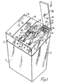
- Fig. 1 is a perspective view of a cooling device according to the invention,
- Fig. 2 is a perspective device of a portion of the cooling device of Fig. 1,
- Fig. 3 is a partly diagrammatic front cross-section elevational view of the cooling device of Fig. 1,
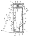
- fig. 4 is a side cross-section elevational view of a portion of the cooling device of Fig. 1,
- Fig. 5 is a circuit diagram of circuitry of the cooling device of Fig. 1 illustrated in combination with a plan view of the cooling device of Fig. 1.
- Fig. 6 is a circuit diagram of a portion of the circuitry of the cooling device of Fig. 1 illustrating the circuitry in combination with a single chilling trough of the cooling device of Fig. 1,
- Fig. 7 is a view similar to Fig. 4 of a cooling device according to another embodiment of the invention, and
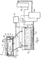
- Fig. 8 is a view similar to Fig. 6 of a circuit diagram of a portion of circuitry of a cooling device according to another embodiment of the invention, the circuitry being illustrated in combination with a single chilling trough, and a single heating trough of the cooling device.
-
- Referring to the drawings and initially to Figs. 1 to 6 there is illustrated a cooling device according to the invention indicated generally by the
reference numeral 1 for coolingwine bottles 2 to a desired chill temperature, typically, 5°C. Thecooling device 1 is of cabinet type construction and comprises ahousing 3 which is supported on four ground engaging castors (not shown). In this embodiment of the invention thehousing 3 is of approximately 700mm in height, and is of area in plan view 900mm in width by 525mm fromfront 5 to rear 6. - Four
chilling troughs 8 are formed in atop panel 9 for receiving fourbottles 2 of wine lying on their respective sides, and also for receiving a liquid heat transfer medium, for cooling thewine bottles 2. Thechilling troughs 8 are identical to each other, and eachchilling trough 8 defines a hollowinterior region 10 which in plan view substantially defines the outline of a longitudinal cross-section of a wine bottle. Eachchilling trough 8 defines a longitudinally extendingcentral axis 12, and thebottles 2 are placed in thechilling troughs 8 with a longitudinal central axis of the respective bottles extending generally parallel to thecentral axis 12 of the correspondingchilling trough 8. Thechilling troughs 8 are arranged side by side adjacent each other with their respectivecentral axes 12 parallel to each other. Eachchilling trough 8 defines an upwardly facingopen mouth 15 which is closed by alid 16. Thelids 16 of the respectivechilling troughs 8 are hingedly connected to the top panel 9 of thehousing 3 adjacent the rear 6 thereof by respective hinges 17. Eachlid 16 is hingable from a closed position closing the hollowinterior region 10 of the correspondingchilling trough 8 to an open position for providing access to awine bottle 2 through theopen mouth 15 to the hollowinterior region 10. One of thelids 16 is illustrated in the open position in Fig. 1, and three are illustrated in the closed position. - A refrigerating means comprises a
reservoir 20 for the liquid heat transfer medium and arefrigeration circuit 21 for maintaining the liquid heat transfer medium in thereservoir 20 at a predetermined temperature, which in this embodiment of the invention is -20°C. Thereservoir 20 andrefrigeration circuit 21 are located within thehousing 3 beneath thechilling troughs 8, see Fig. 3. In this embodiment of the invention the liquid heat transfer medium is an aqueous solution of propylene glycol, the proportion of propylene glycol being such that the freezing point of the aqueous solution is below -20°C, and preferably is in the order of -25°C. A plurality of flow means, namely, fourflow pipes 23, one for eachchilling trough 8 connect the respectivechilling troughs 8 independently of each other to thereservoir 20 for receiving heat transfer medium therefrom. Theflow pipes 23 are connected torespective inlet ports 25 of thechilling troughs 8. A common return means, namely, acommon return pipe 27 returns the heat transfer medium from the respectivechilling troughs 8 to thereservoir 20. - A level control comprising an
outlet weir 28 is provided in a rearaxial end wall 29 of eachchilling trough 8 over which heat transfer medium flows from the respectivechilling troughs 8 for maintaining the level of heat transfer medium in thechilling troughs 8 at a predetermined level, which is above awine bottle 2 when thewine bottle 2 is lying on its side in thechilling trough 8. In other words, eachoutlet weir 28 maintains the level of heat transfer medium in its correspondingchilling trough 8 so that awine bottle 2 placed in thechilling trough 8 is completely submerged in the heat transfer medium. Anelongated collection channel 30 extends adjacent therear end wall 29 transversely of thechilling troughs 8 and communicates with thechilling troughs 8 over theoutlet weirs 28 for receiving heat transfer medium from the respectivechilling troughs 8. Thecollection channel 30 slopes downwardly towards a centrally locatedoutlet port 31 for the draining heat transfer medium through theoutlet port 31. Thecommon return pipe 27 is connected to theoutlet port 31 for returning the heat transfer medium to thereservoir 20. - Four circulating means, namely, four electrically powered circulating pumps 34, one for each
chilling trough 8 are located, one in eachflow pipe 23 for circulating heat transfer medium from thereservoir 20 to the respectivechilling troughs 8 under the control of a control means, namely, acontrol circuit 35 which is illustrated in block representation only. The circulating pumps 34 are independently operable under the control of thecontrol circuit 35 for delivering heat transfer medium into the correspondingchilling trough 8 independently of the otherchilling troughs 8 and for circulating the heat transfer medium independently through thechilling troughs 8. Therefrigeration circuit 21 is also operated under the control of thecontrol circuit 35. - The
inlet ports 25 to the respectivechilling troughs 8 are located at the lowest point of the hollowinterior region 10 of eachchilling trough 8 for facilitating draining of the respectivechilling troughs 8 through thecorresponding inlet port 25. The circulating pumps 34 are of the type which when deactivated permit return flow of heat transfer medium therethrough to thereservoir 20. Thus, a drain means is provided for draining the heat transfer medium from eachchilling trough 8 when the corresponding circulatingpump 34 has been deactivated. - A first detecting means for detecting the presence of a
wine bottle 2 in the respectivechilling troughs 8 comprises fourfirst sensors 38, namely four plunger type operated micro-switches, one for eachchilling trough 8. The respectivefirst sensors 38 are located on therespective lids 16 andplungers 39 of thefirst sensors 38 extend into the hollowinterior regions 10 of thechilling troughs 8 when the correspondinglids 16 are in the closed position for engaging awine bottle 2 in thechilling troughs 8. A second detecting means for detecting when thelids 16 of the respectivechilling troughs 8 are in the closed position comprises foursecond sensors 40, namely, plunger type operated micro-switches, one being provided for eachchilling trough 8. Thesecond sensors 40 are located in thehousing 3 beneath the top plate 9, andplungers 41 of the respectivesecond sensors 40 extend through the top plate 9 for engaging thelid 16 of the correspondingchilling trough 8. The first andsecond sensors control circuit 35 and their status is read by thecontrol circuit 35. A microprocessor 42 in thecontrol circuit 35 controls thecontrol circuit 35 for in turn controlling therefrigeration circuit 21 and for operating the circulating pumps 34 in response to the first andsecond sensors - A timing means, namely, a
timer 43 in thecontrol circuit 35 times three predetermined periods of time, namely, a first predetermined period of time, a second predetermined period of time and a third predetermined period of time for eachchilling trough 8. The circulating pumps 34 are continuously operated during the first predetermined period of time for circulating heat transfer medium from thereservoir 20 through thechilling troughs 8 for cooling awine bottle 2 in the correspondingchilling troughs 8 to the desired chill temperature. At the end of the first predetermined period of time the circulatingpump 34 remains deactivated. The second predetermined period of time is timed by thetimer 43 immediately at the end of the first predetermined period of time, and during the second predetermined period of time the relevant circulatingpump 34 is deactivated. The third predetermined period of time is timed by thetimer 43 at the end of the second predetermined period of time if thewine bottle 2 has not been removed from the relevantchilling trough 8 during the second predetermined period of time. During the third predetermined period of time the circulatingpump 34 corresponding to the relevantchilling trough 8 is again operated for circulating the heat transfer medium for maintaining the temperature of thewine bottle 2 at the desired chill temperature while thewine bottle 2 is left in thechilling trough 8. Thetimer 43 under the control of the microprocessor 42 continues to sequentially time second predetermined periods of time and third predetermined periods of time for so long as the wine bottle remains in thechilling trough 8 for maintaining thewine bottle 8 at the desired chill temperature. Thetimer 43 times first, second and third periods of time for the correspondingchilling troughs 8 and the circulating pumps 34 independently of each other. - In this embodiment of the invention the first predetermined period of time timed by the
timer 43 is approximately four minutes. The second predetermined period of time timed by thetimer 43 is approximately four minutes, and the third predetermined period of time is approximately thirty seconds. It has been found that by circulating the heat transfer medium at a temperature of approximately -20°C for four minutes at a flow rate of approximately 1,300ml per minute is sufficient for reducing the temperature of a wine bottle, and needless to say, the contents thereof from room temperature to a desired chill temperature, which typically, is approximately 5°C. It has been found that by circulating the heat transfer medium for a third predetermined period of time of approximately 30 seconds at intervals of four minutes, namely, the second predetermined periods of time is sufficient for maintaining the temperature of the wine bottle and its contents at the desired chill temperature while thewine bottle 2 remains in achilling trough 8 after its temperature has been reduced to the desired chill temperature at the end of the first predetermined period of time. - Referring to Fig. 6, the
refrigeration circuit 21 is a conventional refrigeration circuit which comprises acompressor 45, acondenser 46, an evaporator 47 and anexpansion valve 49, all of which will be well known to those skilled in the art and their inter-connection within therefrigeration circuit 21 will be well known to those skilled in the art. Theexpansion valve 49 is responsive to atemperature sensor 50 which monitors the temperature of the refrigerant from the evaporator 47. Atemperature sensor 52 is located in thereservoir 20 for monitoring the temperature of the heat transfer medium in thereservoir 20. Thetemperature sensor 52 is read by thecontrol circuit 35. The evaporator 47 andcompressor 45 are operated under the control of thecontrol circuit 35 in response to thesensor 52 for maintaining the temperature of the heat transfer medium at approximately -20°C in thereservoir 20. - The lower profile of each
chilling trough 8 in side elevational view is shaped to have a raisedportion 54 and alower portion 55, see Fig. 4. The height of the raisedportion 54 above thelower portion 55 is such that when a wine bottle is placed in the hollowinterior region 10, the side wall of the bottle adjacent the base rests on thelower portion 55, and the neck of the bottle is supported on the raisedportion 54 with most of the side wall of the bottle spaced apart above thelower portion 55, see Fig. 4. This facilitates circulation of the heat transfer medium substantially around the entire circumference of thewine bottle 2 along substantially the entire length of thewine bottle 2. Theinlet port 25 of eachchilling trough 8 is located in thelower portion 55 of thechilling trough 8. - In use, when a
wine bottle 2 is placed in one of thechilling troughs 8 and thelid 16 is closed, theplunger 39 of the correspondingfirst sensor 38 is depressed by engaging thewine bottle 2, thereby closing the micro-switch of thefirst sensor 38, and delivering a signal to thecontrol circuit 35 indicating that a wine bottle has been placed in the relevantchilling trough 8. Theplunger 41 of thesecond sensor 40 is depressed on engaging thelid 16, and closes the micro-switch of thesecond sensor 40, thereby sending a signal to thecontrol circuit 35 indicating that thelid 16 of the relevantchilling trough 8 is closed. On receiving the signals from the first andsecond sensors control circuit 35 activates the circulatingpump 34 which corresponds to thechilling trough 8 in which thewine bottle 2 has been placed and thelid 16 has been closed, thereby circulating heat transfer medium from thereservoir 20 through theflow pipe 23 into the relevantchilling trough 8, and thetimer 43 commences to time the first predetermined period of time of four minutes. On the heat transfer medium rising to the level of theoutlet weir 28 of thechilling trough 8, the heat transfer medium flows over theoutlet weir 28 into the collectingchannel 30, and is returned through thecommon return pipe 27 to thereservoir 20. The circulatingpump 34 is continuously operated for the duration of the first predetermined period of time for continuously circulating the heat transfer medium through thechilling trough 8. - When the
timer 43 has timed the first predetermined period of time the circulatingpump 34 is deactivated. Deactivation of the circulatingpump 35 permits heat transfer medium in thechilling trough 8 to return through theflow pipe 23 to thereservoir 20, thereby draining thechilling trough 8 and thewine bottle 2 and its contents at this stage are chilled to the desired chill temperature of approximately 3°C. By opening thelid 16 thewine bottle 2 may be removed from thechilling trough 8 and is ready for use. - At the end of the first predetermined period of time, the
timer 43 commences to time the second predetermined period of time also of four minutes. At the end of the second predetermined period of time should thewine bottle 2 not have been removed from thechilling trough 8, thetimer 43 commences to time a third period of time of approximately thirty seconds, and thecontrol circuit 35 reactivates the relevant circulatingpump 34 for again circulating heat transfer medium through thechilling trough 8 continuously for the duration of the third predetermined period of time for returning and maintaining the temperature of the wine and thewine bottle 2 at the desired chill temperature of approximately 3°C. Thetimer 43 continues to alternatively and sequentially time second and third predetermined periods of time until thewine bottle 2 has been removed from thechilling trough 8. The presence or otherwise of awine bottle 2 in achilling trough 8 during the second and third periods of time is determined by thecontrol circuit 35 from the status of thefirst sensor 38 of thatchilling trough 8. - On the
wine bottle 2 having been removed from thechilling trough 8 thefirst sensor 38 and thesecond sensor 40 reset the part of thecontrol circuit 35 which controls the circulatingpump 34 which corresponds to that chilling trough for timing a cooling cycle for the next wine bottle in thatchilling trough 8. - Referring now to Fig. 7 there is illustrated a portion of a cooling device according to another embodiment of the invention, which is indicated generally by the
reference numeral 60. Thecooling device 60 is substantially similar to thecooling device 1, and similar components are identified by the same reference numerals. Fourchilling troughs 8 are provided in thecooling device 60. The main difference between the coolingdevice 60 and thecooling device 1 is that a means for moving thewine bottle 2 within eachchilling trough 6 is provided for causing circulation of the wine within thewine bottle 2 for facilitating heat transfer between the wine in thewine bottle 2 and the heat transfer medium. In this embodiment of the invention the means for moving thewine bottle 2 rotates the wine bottle about its longitudinally extending central axis, and comprises a gripping means which is provided by a cup shapedgrip 62 for engaging thewine bottle 2 adjacent its end. Thegrip 62 is carried on a shaft 63 which is rotatable in bearings (not shown) in therear end wall 29 and anend wall 65 which are formed in the top plate 9. A drive means, namely, an electricallypowered motor 66 is located and mounted in a sub-housing (not shown) which extends from the rear of thehousing 3 for driving the shaft 63 for in turn rotating thegrip 62. Onegrip 62, one shaft 63 and onemotor 66 are provided for eachchilling trough 8, and themotors 66 are operated independently of each other under the control of thecontrol circuit 35 in the same sequence as the corresponding circulating pumps 34. In other words, when the circulating pumps 34 of the respectivechilling troughs 8 are operated, the correspondingmotor 66 is also operated for rotating the wine bottle in the relevantchilling trough 8. Themotors 66 are operated to drive thegrips 62 at a speed of approximately 30 revs per minute. It has been found that by rotating a wine bottle in thechilling trough 8 at a speed of approximately 30 revs per minute sufficient circulation of wine within the wine bottle takes place to improve heat transfer efficiency between the wine in the wine bottle and the heat transfer medium for significantly reducing the time required for chilling the wine bottle to the desired chill temperature. It is envisaged that a wine bottle may be rotated by thegrip 62 at rotational speeds in the range of 20 revs per minute to 40 revs per minute, and preferably, speeds in the range of 28 revs per minute to 32 revs per minute. Ideally, the rotational speed of eachgrip 62 should be maintained constant. - Referring now to Fig. 8, there is illustrated a diagrammatic view of a portion of a cooling device according to another embodiment of the invention which is indicated generally by the
reference numeral 70. Thecooling device 70 is substantially similar to thecooling device 1, and similar components are identified by the same reference numerals. The main difference between the coolingdevice 70 and thecooling device 1 is that as well as having fourchilling troughs 8 for coolingbottles 2 of wine, thecooling device 1 also comprises twoheating troughs 71 for raising the temperature of respective containers, in this case,bottles 2 of red wine to a desired temperature. In Fig. 8, only onechilling trough 8 and oneheating trough 71 are illustrated. Eachheating trough 71 is identical to thechilling troughs 8, and the chilling andheating troughs central axes 12 parallel to each other. The twoheating troughs 71 are located together, and the fourheating troughs 8 are located together. Waste heat from therefrigeration circuit 21 is used for heating a second liquid heat transfer medium, which in this case is water for raising the temperature ofrespective wine bottles 2 in theheating troughs 71. Asecond reservoir 72 is located in thehousing 3 within which the water heat transfer medium is heated. A pair of second circulating means, namely, circulating pumps 74 which are identical to the circulating pumps 34 independently circulate heated water from thereservoir 72 through respective second flow means, namely,flow pipes 75 to thecorresponding heating troughs 71 throughrespective inlet ports 76. The circulating pumps 74,flow pipes 75 andinlet ports 76 are identical to the circulatingpump 34,flow pipes 23 andinlet ports 25, respectively. Level control means for maintaining the level of water in theheating troughs 71 at a level to completely submerge thewine bottles 2 are provided byoutlet weirs 77 which are identical to theoutlet weirs 28 of thechilling troughs 8. Acollection channel 78 located at the rear end of the twoheating troughs 71 collects water from theoutlet weirs 77 which is returned through acommon return pipe 79 to thereservoir 72. Eachheating trough 71 is closed by alid 16 which is hingedly connected by ahinge 17 to the top panel 9 in similar fashion as thelids 16 close thechilling troughs 8. Aseparate lid 16 is provided for eachheating trough 71. Third and fourth detector means provided by third and fourth plunger type operatedmicro-switch sensors 80 and 81, respectively, detect the presence of abottle 2 in eachheating trough 71, and thelid 16 of thatheating trough 71 in the closed position, respectively. Separate third andfourth sensors 80 and 81 are provided for eachheating trough 71 and thesensors 80 and 81 are identical to the first andsecond sensors fourth sensors 80 and 81 are read by thecontrol circuit 35. - In this embodiment of the invention, the
condenser 46 of therefrigeration circuit 21 is replaced by thereservoir 72, and refrigerant of therefrigeration circuit 21 is passed through aheat exchange coil 83 located in thereservoir 72 for cooling the refrigerant, and in turn heating the water in thereservoir 72. In this way, waste heat from therefrigeration circuit 21 is stored in the water in thereservoir 72. - An auxiliary heating means, in this case an electrically
powered immersion heater 85 is located in thewater reservoir 72 for boosting the heat of the water therein should this be necessary. Theimmersion heater 85 is operated under the control thecontrol circuit 35 in response to atemperature sensor 86 located in thewater reservoir 72 for monitoring the water temperature. - Operation of the
cooling device 70 is identical to thecooling device 1 insofar as thechilling troughs 8 are concerned. Operation of theheating troughs 71 is also substantially similar to the operation of thechilling troughs 8. Typically, the temperature of the water in thewater reservoir 72 is maintained at approximately 30°C by the heating effect of theheat exchange coil 83. In the event that the temperature of the water in thewater reservoir 72 falls below 30°C, thecontrol circuit 35 activates the immersion heater for raising the temperature to 30°C. The circulating pumps 74 are operated independently of each other by thecontrol circuit 35, and in response to the third andfourth sensors 80 and 81 detecting abottle 2 in one of theheating troughs 71 and the correspondinglid 16 being closed the corresponding circulatingpump 74 is operated for circulating water from thereservoir 72 through therelevant heating trough 71 which is returned to thereservoir 72 through thecommon return pipe 79. - The
timer 43 in thecontrol circuit 35 times similar first, second and third predetermined periods of time for operating the circulatingpump 74 of theheating trough 71 in which awine bottle 2 is placed for heating in similar fashion as the first, second and third predetermined periods are timed in connection with thechilling troughs 1. In this embodiment of the invention, the first, second and third predetermined periods of time will be substantially similar to the first, second and third predetermined periods of time of thechilling troughs 8. - The advantage of this embodiment of the invention is that as well as being capable of cooling
wine bottles 2 to a desired chill temperature, thecooling device 70 may also be used to heat wine bottles, typically red wine, to a desired temperature, and a particularly important advantage of the invention is that the wine bottles, in general, can be raised to the desired temperature without the need for additional heat from theimmersion heater 85, since, in general, it has been found that the waste heat from therefrigeration circuit 21 is adequate for raising the temperature of wine bottles and the contents thereof to the desired temperature. - It is also envisaged that instead of using a water heat transfer medium for transferring the waste heat from the
refrigeration circuit 21 for heating the bottles, air may be used as the heat transfer medium, and in which case the bottles to be heated would be placed in a compartment adjacent the condenser of the refrigeration circuit of thecooling device 1 for heating thereof by the waste heat from the condenser. - While the cooling devices have been described as comprising four chilling troughs, it will be readily apparent to those skilled in the art that the cooling devices may be provided with any number of chilling troughs. For example, in certain cases, a cooling device with a single chilling trough may be provided, and indeed, it is expected that an advantageous form of the cooling device may be one which comprises two chilling troughs.
- It will also be appreciated that each chilling trough may be of any other suitable shape, and indeed, it is envisaged in certain cases that the chilling troughs may be oriented for receiving a wine bottle in a different orientation, for example, standing vertically upwards.
- Needless to say, while the heat transfer medium has been described as being an aqueous solution of propylene glycol, any other suitable heat transfer medium may be provided, and it will of course be appreciated that the heat transfer medium may be maintained at any other desired temperature besides -20°C. In cases where the heat transfer medium is to be maintained at a higher temperature than -20°C, it is envisaged that the proportion of propylene glycol in the aqueous solution may vary for raising the freezing point of the heat transfer medium. It will also be appreciated that the first predetermined period of time during which the heat transfer medium is continuously circulated through each chilling trough for cooling a wine bottle may be varied, and in cases where the heat transfer medium is maintained at a higher temperature than -20°C, for example, -13°C, the time to reduce the wine bottle and its contents to the desired chill temperature may be longer. Similarly, the second and third predetermined periods of time may be altered appropriately depending on the temperature at which the heat transfer medium is maintained. Needless to say, it will be appreciated that under varying circumstances, for example, a difference in room temperature between winter and summer, the first, second and third predetermined periods of time may also be varied and/or the temperature at which the heat transfer medium is maintained in order to achieve the desired chill temperature of the wine bottle and its contents may be varied.
Claims (16)
- A cooling device for cooling a beverage in a container (2) such as a bottle or a can, the cooling device (1) comprising a chilling trough (8) for receiving the container (2), a refrigerating means (20,21) for chilling a liquid heat transfer medium, and a circulating means (34) for circulating the heat transfer medium between the refrigerating means (20,21) and the chilling trough (8) and through the chilling trough (8) for cooling the container (2) therein, characterised in that a means (62, 66) is provided for moving the container (2) within the chilling trough (8) for causing circulation of the contents of the container (2) within the container (2) for improving the heat transfer efficiency between the heat transfer medium and the contents of the container (2).
- A cooling device as claimed in Claim 1 characterised in that the means (62,66) for moving the container (2) rotates the container (2) about a longitudinally extending central axis of the container (2).
- A cooling device as claimed in Claim 1 or 2 characterised in that the means (62,66) for moving the container (2) comprises a gripping means (62) for gripping the container (2), the gripping means (62) being located in the chilling trough (8) adjacent an axial end (29) thereof, and a drive means (66) for rotating the gripping means (62).
- A cooling device as claimed in any preceding claim characterised in that the chilling trough (8) is an elongated chilling trough (8) defining a longitudinally extending central axis (12) for receiving an elongated container (2) with the central axis of the container (2) lying substantially parallel to the central axis (12) of the chilling trough (8), the chilling trough (8) being disposed with the longitudinally extending central axis (12) thereof extending substantially horizontally.
- A cooling device as claimed in Claim 4 characterised in that the chilling trough (8) defines a hollow interior region (10) for receiving the container (2), and an upwardly facing open mouth (15) for providing access to the hollow interior region (10).
- A cooling device as claimed in Claim 5 characterised in that the open mouth (15) substantially defines the longitudinal cross-section of the container (2), and a lid (16) is provided for closing the open mouth (15) of the chilling trough (8), the lid (16) being moveable between a closed position closing the open mouth (15), and an open position providing access through the open mouth (15) to the hollow interior region (10) of the chilling trough (8).
- A cooling device as claimed in Claim 6 characterised in that a first detecting means (38) is provided for detecting the presence of a container (2) in the chilling trough (8), and a second detecting means (40) is provided for detecting the lid (16) in the closed position.
- A cooling device as claimed in Claim 7 characterised in that a control means (35) is provided for controlling the operation of the circulating means (34), the control means (35) being responsive to the first and second detecting means (38,40) detecting the presence of a container (2) in the chilling trough (8), and the lid (16) of the chilling trough (8) being in the closed position for activating the circulating means (34) for circulating the heat transfer medium through the chilling trough (8) for a first predetermined period of time which is timed by a timing means for cooling the container (2) to a desired temperature.
- A cooling device as claimed in Claim 8 characterised in that the timing means (43) times a second predetermined period of time from the end of the first predetermined period of time, and the control means (35) is responsive to the timing means (43) having timed the second predetermined period of time for activating the circulating means (34) for circulating the heat transfer medium through the chilling trough (8) for a third predetermined period of time which is timed by the timing means, in the event that the container (2) has not been removed from the chilling trough (8) after the end of the second predetermined period of time for maintaining the container (2) at the desired temperature.
- A cooling device as claimed in any preceding claim characterised in that a level control means (28) is provided for controlling the level of the heat transfer medium in the chilling trough (8).
- A cooling device as claimed in Claim 10 characterised in that the level control means (28) comprises an outlet weir (28) over which heat transfer medium flows from the chilling trough (8).
- A cooling device as claimed in Claim 10 or 11 characterised in that the level control means (28) is provided for controlling the level of the heat transfer medium in the chilling trough (8) so that the container (2) is submerged in the heat transfer medium during cooling thereof.
- A cooling device as claimed in any preceding claim characterised in that a return means (27) is provided for returning heat transfer medium from the chilling trough (8) to the refrigerating means (20,21), and a flow means (23) is provided for accommodating the heat transfer medium from the refrigerating means (20,21) to the chilling trough (8), the circulating means (34) co-operating with the flow means (23) for delivering heat transfer medium to the chilling trough (8).
- A cooling device as claimed in any preceding claim characterised in that a plurality of chilling troughs (8) are provided, each chilling trough (8) having an associated circulating means (34), the circulating means (34) of each chilling rough being operable independently of the respective circulating means (34) of the other chilling troughs (8).
- A cooling device as claimed in claim 14 characterised in that each chilling trough (8) is adapted for receiving one wine bottle (2).
- A cooling device as claimed in any preceding claim characterised in that a heating compartment (71) for heating a container (2) is provided, and a second heat transfer medium transfers waste heat from the refrigerating means (21) to the heating compartment for heating the container (2) therein.
Applications Claiming Priority (3)
| Application Number | Priority Date | Filing Date | Title |
|---|---|---|---|
| IE960220 | 1996-03-15 | ||
| IE960220 | 1996-03-15 | ||
| PCT/IE1997/000018 WO1997035155A1 (en) | 1996-03-15 | 1997-03-18 | A cooling device |
Publications (2)
| Publication Number | Publication Date |
|---|---|
| EP0886750A1 EP0886750A1 (en) | 1998-12-30 |
| EP0886750B1 true EP0886750B1 (en) | 2003-04-23 |
Family
ID=11041110
Family Applications (1)
| Application Number | Title | Priority Date | Filing Date |
|---|---|---|---|
| EP97915656A Expired - Lifetime EP0886750B1 (en) | 1996-03-15 | 1997-03-18 | A cooling device |
Country Status (4)
| Country | Link |
|---|---|
| EP (1) | EP0886750B1 (en) |
| AU (1) | AU2304897A (en) |
| DE (1) | DE69721244D1 (en) |
| WO (1) | WO1997035155A1 (en) |
Families Citing this family (21)
| Publication number | Priority date | Publication date | Assignee | Title |
|---|---|---|---|---|
| FR2788677B1 (en) * | 1999-01-26 | 2001-03-30 | Seb Sa | APPARATUS FOR PROVIDING CONDITIONED BEVERAGES TO TEMPERATURE |
| GB9903685D0 (en) * | 1999-02-19 | 1999-04-14 | Bullivant Nicholas T | Rapid fluid cooler |
| FR2790543A1 (en) * | 1999-03-03 | 2000-09-08 | Elie Kalfon | MODULAR FAST LIQUID COOLING SYSTEM |
| IL152816A0 (en) * | 2000-05-18 | 2003-06-24 | Supachill Internat Pty Ltd | Cooling method for controlled high speed chilling or freezing |
| CZ20031811A3 (en) | 2001-01-02 | 2004-02-18 | Supachill Technologies Pty. Ltd. | Process for preparing samples of tissues for histological and pathological investigation and a system for making the same |
| US7707848B2 (en) | 2001-03-01 | 2010-05-04 | The Cooper Union For The Advancement Of Science And Art | Rapid fluid cooling system and refrigeration device having same |
| WO2002070970A2 (en) * | 2001-03-01 | 2002-09-12 | Revolutionary Cooling Systems, Inc. | Rapid fluid cooling and heating device and method |
| US6656380B2 (en) | 2001-10-16 | 2003-12-02 | Supachill Technologies Pty. Ltd. | Super-coolable composition having long-duration phase change capability, process for preparation of same, process for super-cooling same and articles comprising same |
| US6681581B2 (en) | 2001-11-20 | 2004-01-27 | Supachill Technologies Pty. Ltd. | Pre-conditioned solute for use in cryogenic processes |
| EP1650514A1 (en) * | 2004-10-20 | 2006-04-26 | Remo Guerra | A dispenser for spirits |
| US7343748B2 (en) * | 2005-12-29 | 2008-03-18 | Whirlpool Corporation | Device for rapidly chilling articles in a refrigerator |
| US9497988B2 (en) | 2007-03-07 | 2016-11-22 | The Cooper Union | Rapid fluid cooling system and method for hot bulk liquids and container therefor |
| US8783058B2 (en) | 2007-03-07 | 2014-07-22 | The Cooper Union For The Advancement Of Science And Art | Compact rapid chilling device and compact method of rapidly chilling contained liquids |
| US8001795B2 (en) * | 2007-07-27 | 2011-08-23 | The Coca-Cola Company | Method of adjusting temperatures of products to desired product temperatures |
| EP2446424A1 (en) | 2009-06-25 | 2012-05-02 | Cambridge Design Research LLP | Dispensing apparatus and methods |
| WO2017218653A1 (en) * | 2016-06-14 | 2017-12-21 | John Lauchnor | Modular retrofit quench unit |
| US11619436B2 (en) | 2019-04-08 | 2023-04-04 | Blue Quench Llc | Containers and methods and devices for enhancing thermal energy transfer between container contents and external environment |
| US11852407B2 (en) | 2012-12-21 | 2023-12-26 | Blue Quench Llc | Device for altering temperature of beverage containers |
| US9810473B2 (en) * | 2012-12-21 | 2017-11-07 | Blue Quench Llc | Modular retrofit quench unit |
| US10174995B2 (en) | 2012-12-21 | 2019-01-08 | Blue Quench Llc | Modular retrofit quench unit |
| GB2530327A (en) * | 2014-09-22 | 2016-03-23 | 42 Technology Ltd | Heat transfer apparatus |
Family Cites Families (12)
| Publication number | Priority date | Publication date | Assignee | Title |
|---|---|---|---|---|
| US2418300A (en) * | 1944-06-22 | 1947-04-01 | Earl Hovey C | Constant level tank for vending machines |
| FR1014754A (en) * | 1950-03-17 | 1952-08-21 | Improvements to processes and apparatus for drafting beer and cooling beverages | |
| US3888092A (en) * | 1973-12-26 | 1975-06-10 | James I Fisher | Device for changing the temperature of containers and their contents |
| FR2305935A1 (en) * | 1975-04-01 | 1976-10-29 | Locolas Claude | Conditioning cabinet for dough in bakeries - with separate power unit and programmer |
| US4164851A (en) * | 1977-12-19 | 1979-08-21 | Bryant Jon A | Beverage container cooler |
| DE2939122A1 (en) * | 1979-09-27 | 1981-04-16 | Hans Fick | Portable cold accumulator charging in deep freeze store - involves holding several accumulators in close contact with several deep cooled walls and maintaining contact during charging |
| EP0174170A3 (en) * | 1984-09-07 | 1988-06-08 | Castleton, Inc. | Method and apparatus for chilling and freezing articles |
| US4549409A (en) * | 1985-03-21 | 1985-10-29 | Smith Jeffrey I | Apparatus for cooling beverage containers and the like |
| BR8707513A (en) * | 1986-10-23 | 1989-02-21 | Phillip Blake Provest | REFRIGERATION APPLIANCE |
| FR2632713B1 (en) * | 1988-06-13 | 1990-09-21 | Frigelice Sarl | RAPID COOLING DEVICE AND METHOD FOR IMPLEMENTING THE DEVICE |
| IT1232419B (en) * | 1989-07-26 | 1992-02-17 | Grassi Luca | APPARATUS FOR QUICK COOLING OF LIQUIDS IN CONTAINERS |
| BE1004012A3 (en) * | 1990-12-17 | 1992-09-08 | F R J Concept | Refresh device for liquids contained in containers. |
-
1997
- 1997-03-18 EP EP97915656A patent/EP0886750B1/en not_active Expired - Lifetime
- 1997-03-18 DE DE69721244T patent/DE69721244D1/en not_active Expired - Lifetime
- 1997-03-18 WO PCT/IE1997/000018 patent/WO1997035155A1/en active IP Right Grant
- 1997-03-18 AU AU23048/97A patent/AU2304897A/en not_active Abandoned
Also Published As
| Publication number | Publication date |
|---|---|
| EP0886750A1 (en) | 1998-12-30 |
| WO1997035155A1 (en) | 1997-09-25 |
| AU2304897A (en) | 1997-10-10 |
| DE69721244D1 (en) | 2003-05-28 |
Similar Documents
| Publication | Publication Date | Title |
|---|---|---|
| EP0886750B1 (en) | A cooling device | |
| US7703301B2 (en) | Rapid fluid cooling system and refrigeration device having same | |
| US5191773A (en) | Recirculating chilling apparatus with a submerged electric motor and impeller | |
| AU596950B2 (en) | Method and apparatus for chilling and freezing articles | |
| EP1364175B1 (en) | Rapid fluid cooling and heating device and method | |
| US4715195A (en) | Apparatus for rapid cooling of containers | |
| US20080271475A1 (en) | Refrigerator having compartment capable of converting between refrigeration and freezing temperatures | |
| US2572508A (en) | Ice maker and bottle cooler | |
| US4437319A (en) | Beverage dispensing device | |
| GB2354061A (en) | Cold storage appliance | |
| CN101363680B (en) | Fast-cooling device for bottle-packaged, can-packaged and box-packaged drinks | |
| US4448036A (en) | Refrigeration system | |
| US20220018589A1 (en) | Stand-alone ice and beverage appliance | |
| IES75685B2 (en) | A cooling device | |
| CN110986472A (en) | Device capable of rapidly cooling beer and beverage and refrigerator with device | |
| EP2095044B1 (en) | Method and device for cooling products | |
| CN219199645U (en) | Refrigerator with a refrigerator body | |
| EP0927860A1 (en) | Instantaneous cooler for liquids and the like or solids | |
| KR20030028470A (en) | Cooling method for controlled high speed chilling or freezing | |
| AU638270B2 (en) | Chilling apparatus | |
| CN220489475U (en) | Dry-wet dual-purpose water-cooled showcase | |
| EP4159095A1 (en) | Apparatus for cooking food and blast chilling the tempreature of said food, and associated method | |
| CN220062257U (en) | Ultralow temperature freezing preservation box | |
| US2318309A (en) | Device for refrigerating beverages | |
| KR100215764B1 (en) | Cooling apparatus for making bean curd |
Legal Events
| Date | Code | Title | Description |
|---|---|---|---|
| PUAI | Public reference made under article 153(3) epc to a published international application that has entered the european phase |
Free format text: ORIGINAL CODE: 0009012 |
|
| 17P | Request for examination filed |
Effective date: 19980929 |
|
| AK | Designated contracting states |
Kind code of ref document: A1 Designated state(s): DE ES FR GB IE PT |
|
| 17Q | First examination report despatched |
Effective date: 20010418 |
|
| GRAH | Despatch of communication of intention to grant a patent |
Free format text: ORIGINAL CODE: EPIDOS IGRA |
|
| GRAH | Despatch of communication of intention to grant a patent |
Free format text: ORIGINAL CODE: EPIDOS IGRA |
|
| GRAA | (expected) grant |
Free format text: ORIGINAL CODE: 0009210 |
|
| AK | Designated contracting states |
Designated state(s): DE ES FR GB IE PT |
|
| PG25 | Lapsed in a contracting state [announced via postgrant information from national office to epo] |
Ref country code: FR Free format text: LAPSE BECAUSE OF FAILURE TO SUBMIT A TRANSLATION OF THE DESCRIPTION OR TO PAY THE FEE WITHIN THE PRESCRIBED TIME-LIMIT Effective date: 20030423 |
|
| REG | Reference to a national code |
Ref country code: GB Ref legal event code: FG4D |
|
| REF | Corresponds to: |
Ref document number: 69721244 Country of ref document: DE Date of ref document: 20030528 Kind code of ref document: P |
|
| REG | Reference to a national code |
Ref country code: IE Ref legal event code: FG4D |
|
| PG25 | Lapsed in a contracting state [announced via postgrant information from national office to epo] |
Ref country code: PT Free format text: LAPSE BECAUSE OF FAILURE TO SUBMIT A TRANSLATION OF THE DESCRIPTION OR TO PAY THE FEE WITHIN THE PRESCRIBED TIME-LIMIT Effective date: 20030723 |
|
| PG25 | Lapsed in a contracting state [announced via postgrant information from national office to epo] |
Ref country code: DE Free format text: LAPSE BECAUSE OF FAILURE TO SUBMIT A TRANSLATION OF THE DESCRIPTION OR TO PAY THE FEE WITHIN THE PRESCRIBED TIME-LIMIT Effective date: 20030724 |
|
| PG25 | Lapsed in a contracting state [announced via postgrant information from national office to epo] |
Ref country code: ES Free format text: LAPSE BECAUSE OF FAILURE TO SUBMIT A TRANSLATION OF THE DESCRIPTION OR TO PAY THE FEE WITHIN THE PRESCRIBED TIME-LIMIT Effective date: 20031030 |
|
| PLBE | No opposition filed within time limit |
Free format text: ORIGINAL CODE: 0009261 |
|
| STAA | Information on the status of an ep patent application or granted ep patent |
Free format text: STATUS: NO OPPOSITION FILED WITHIN TIME LIMIT |
|
| PG25 | Lapsed in a contracting state [announced via postgrant information from national office to epo] |
Ref country code: IE Free format text: LAPSE BECAUSE OF NON-PAYMENT OF DUE FEES Effective date: 20040318 Ref country code: GB Free format text: LAPSE BECAUSE OF NON-PAYMENT OF DUE FEES Effective date: 20040318 |
|
| 26N | No opposition filed |
Effective date: 20040126 |
|
| EN | Fr: translation not filed | ||
| GBPC | Gb: european patent ceased through non-payment of renewal fee |
Effective date: 20040318 |
|
| REG | Reference to a national code |
Ref country code: IE Ref legal event code: MM4A |