EP0886389A2 - ContrÔle de puissance d'émission pour système de téléphone mobile à AMDC à débit variable - Google Patents
ContrÔle de puissance d'émission pour système de téléphone mobile à AMDC à débit variable Download PDFInfo
- Publication number
- EP0886389A2 EP0886389A2 EP19980111370 EP98111370A EP0886389A2 EP 0886389 A2 EP0886389 A2 EP 0886389A2 EP 19980111370 EP19980111370 EP 19980111370 EP 98111370 A EP98111370 A EP 98111370A EP 0886389 A2 EP0886389 A2 EP 0886389A2
- Authority
- EP
- European Patent Office
- Prior art keywords
- transmission
- electric power
- value
- unit
- bit rate
- Prior art date
- Legal status (The legal status is an assumption and is not a legal conclusion. Google has not performed a legal analysis and makes no representation as to the accuracy of the status listed.)
- Granted
Links
- 230000005540 biological transmission Effects 0.000 title claims abstract description 219
- 230000003247 decreasing effect Effects 0.000 claims abstract description 8
- 238000000034 method Methods 0.000 claims description 36
- 108010003272 Hyaluronate lyase Proteins 0.000 claims description 14
- 238000012545 processing Methods 0.000 claims description 11
- FZNCGRZWXLXZSZ-CIQUZCHMSA-N Voglibose Chemical compound OCC(CO)N[C@H]1C[C@](O)(CO)[C@@H](O)[C@H](O)[C@H]1O FZNCGRZWXLXZSZ-CIQUZCHMSA-N 0.000 claims 1
- 238000010586 diagram Methods 0.000 description 22
- 238000010276 construction Methods 0.000 description 13
- 238000005259 measurement Methods 0.000 description 8
- 238000004364 calculation method Methods 0.000 description 6
- 230000007423 decrease Effects 0.000 description 4
- 238000009792 diffusion process Methods 0.000 description 4
- 230000006866 deterioration Effects 0.000 description 3
- 230000001413 cellular effect Effects 0.000 description 2
- 230000006870 function Effects 0.000 description 2
- 238000007476 Maximum Likelihood Methods 0.000 description 1
- 238000004891 communication Methods 0.000 description 1
- 238000007796 conventional method Methods 0.000 description 1
- 238000012937 correction Methods 0.000 description 1
- 230000001934 delay Effects 0.000 description 1
- 238000001514 detection method Methods 0.000 description 1
- 239000006185 dispersion Substances 0.000 description 1
- 230000000694 effects Effects 0.000 description 1
- 239000000284 extract Substances 0.000 description 1
- 238000005562 fading Methods 0.000 description 1
- 230000005484 gravity Effects 0.000 description 1
- 238000003672 processing method Methods 0.000 description 1
- 238000001228 spectrum Methods 0.000 description 1
- 230000001360 synchronised effect Effects 0.000 description 1
Images


Classifications
-
- H—ELECTRICITY
- H04—ELECTRIC COMMUNICATION TECHNIQUE
- H04W—WIRELESS COMMUNICATION NETWORKS
- H04W52/00—Power management, e.g. TPC [Transmission Power Control], power saving or power classes
- H04W52/04—TPC
- H04W52/18—TPC being performed according to specific parameters
- H04W52/26—TPC being performed according to specific parameters using transmission rate or quality of service QoS [Quality of Service]
- H04W52/267—TPC being performed according to specific parameters using transmission rate or quality of service QoS [Quality of Service] taking into account the information rate
-
- H—ELECTRICITY
- H04—ELECTRIC COMMUNICATION TECHNIQUE
- H04W—WIRELESS COMMUNICATION NETWORKS
- H04W52/00—Power management, e.g. TPC [Transmission Power Control], power saving or power classes
- H04W52/04—TPC
- H04W52/18—TPC being performed according to specific parameters
- H04W52/24—TPC being performed according to specific parameters using SIR [Signal to Interference Ratio] or other wireless path parameters
- H04W52/241—TPC being performed according to specific parameters using SIR [Signal to Interference Ratio] or other wireless path parameters taking into account channel quality metrics, e.g. SIR, SNR, CIR, Eb/lo
Definitions
- the present invention relates to an electric power controlling system for variable bit rate CDMA transmission which is applied to a mobile telephone system (cellular mobile telephone system) or the like using a direct spread code-division multiple accessing (DS-CDMA) system. More particularly, the invention relates to an electric power controlling system for variable bit rate CDMA transmission in which a plurality of bit rates are switched and a mobile telephone system adopting the system.
- a mobile telephone system cellular mobile telephone system
- DS-CDMA direct spread code-division multiple accessing
- IS-95 Standard of North American Standards TIA/EIA is widely known.
- DS-CDMA direct spread code-division multiple accessing
- variable rate transmission is executed in such a manner that transmission data are thinned to 1/2, 1/4, and 1/8, respectively, and the resultant data is transmitted.
- one frame (20 msec) is divided into 16 slots each having an interval of 1.25 msec and, when data are transmitted at the basic rate of 9.6 kbps, the data are transmitted with all of 16 slots.
- the bit rate of 4.8 kbps, 2.4 kbps, or 1.2 kbps data are transmitted with only 8, 4, or 2 slots per one frame and transmission of other slots is stopped.
- the slot transmission is merely turned ON/OFF and a transmission electric power does not depend on the bit rate.
- the base station Since the base station cannot previously know a bit rate at which the mobile terminal transmits, the base station compares the reception electric power with a reference value for all slots and instructs the mobile terminal to increase or decrease the transmission electric power so that the reception electric power coincides with the reference value.
- the mobile terminal controls in accordance with only the instruction of the base station for the slots which have actually been transmitted and ignores the instruction to slots which have not been transmitted.
- the transmission in which one of the four kinds of bit rates of 9.6 kbps, 4.8 kbps, 2.4 kbps, and 1.2 kbps is selected can be similarly executed.
- the variable bit rate of the reverse link it is different from a realizing method for the variable bit rate of the reverse link.
- the low bit rate is not realized by turning ON/OFF the transmission on a slot unit basis, namely, thinning in a manner similar to the reverse link but, for example, in case of 4.8 kbps as shown in Fig. 1, the transmission electric power per one time is controlled to 1/2 instead of executing the transmission by repeating the same bit twice.
- the electric powers per one time are set to 1/4 and 1/8, respectively, instead of repeating the same bit four times and eight times, respectively.
- the transmission electric power per one bit can be held to be constant.
- the problems involved in the reverse link as explained above namely, a deterioration in characteristics due to the restriction of the interleave and hazard noise caused by with the burst transmission can be solved.
- the transmission electric power is dynamically changed depending upon the bit rate in use, it is difficult to control the transmission electric power without previously knowing the bit rate so that the reception electric power per 1-bit information is equalized.
- the reason why the realizing method for the variable bit rate for the forward link is different from that for the reverse link in IS-95 Standard is that the forward link uses a method in which it is unnecessary to execute a high-speed transmission electric power control and in which a deterioration in characteristics is little.
- variable bit rate transmitting system for the reverse link in IS-95 Standard namely, a deterioration in transmitting characteristics caused by delays of the control for the interleave and control for the transmission electric power
- another variable bit rate transmission method for transmitting only part of slots without turning ON/OFF the transmission on a slot unit basis on which the transmission electric power controlled is executed in a manner similar to that in the reverse link of IS-95 Standard for example, a method of transmitting a frame which is transmitted at a bit rate that is 1/2 of the basic rate by using the whole slot in such a manner that the transmission of only the former half of one slot is ON and that of the latter half is OFF.
- variable bit rate transmitting method since ON time per slot for transmission changes depending upon the bit rate, a measuring method for the reception electric power is restricted. For example, when the reception electric power is measured during only interval in which the transmission is ON at even the lowest bit rate, it is possible to prevent measurement of the reception electric power at intervals in which the transmission is OFF. However, there is a problem that measurement interval is shorten, so that a measurement precision is deteriorated.
- variable bit rate for transmission wherein the transmission ON/OFF is effected on a slot unit basis as in the reverse link in IS-95 Standard, its transmitting characteristics are deteriorated.
- variable bit rate transmitting method wherein changing a diffusion rate is changed in correspondence to the bit rate and simultaneously the transmission electric power is changed in inverse proportion to the diffusion rate, as in the forward link in IS-95 Standard, for example, in a method in which the diffusion rate is set to be twice as large as that of the basic rate and the transmission electric power is set to 1/2 of that of the basic rate in a frame in which data are transmitted at a bit rate of 1/2 of the basic rate, it is difficult to measure the reception electric power or a reception quality per 1-bit information.
- variable bit rate transmission with only parts of the slots for example, the method of transmitting a frame in which data are transmitted at a bit rate of 1/2 of the basic rate for the whole slot in such a manner that the transmission of only the former half of one slot is ON and that of the latter half is OFF, the measuring interval of the reception electric power is restricted, with the result that its measurement precision deteriorates.
- the present invention has been made in consideration of the above points and it is the first object of the invention to provide a variable bit rate CDMA transmission electric power control system in which a transmission electric power is controlled at a high precision when it is applied to a variable bit rate transmitting method of transmitting data in such a manner that a transmission quality is not deteriorated, a spread factor is changed depending upon a bit as selected, and a transmission electric power is changed in inverse proportion to the spread factor and a variable bit rate transmission for transmitting only parts of slots depending upon a bit rate in use.
- the second object of the invention is to provide a mobile telephone system adopting the CDMA transmission electric power controlling system according to the invention.
- variable bit rate CDMA transmission electric power controlling system for switching a plurality of bit rates in transmission wherein reception quality is estimated for transmission bit rates obtained from a reception baseband signal and a transmission electric power is controlled on the basis of the reception quality thus estimated.
- the reception quality is estimated by measuring an Eb/Io value that is a ratio of a signal electric energy per bit Eb to an interference electric power per Hz Io value for the plurality of bit rates obtained from a reception base-band signal, obtaining a maximum value of the Eb/Io value, and a transmission electric power is controlled on the basis of the maximum value of the Eb/Io value.
- a variable bit rate CDMA transmission electric power controlling system comprises reception processing means for converting a reception signal to output a reception base-band signal; Eb/Io calculating means for calculating an Eb/Io value that is a ratio of a signal electric energy per bit Eb to an interference electric power per Hz Io for every bit rate in use; maximum value detecting means for detecting a maximum value of the Eb/Io values for all bit rates; comparing means for comparing the maximum Eb/Io value with a target Eb/Io value to produce a transmission electric power control bit instructing so that when the maximum Eb/Io value is large, a transmission electric power is decreased and, when the maximum Eb/Io value is small, the transmission electric power is increased; multiplexing means for multiplexing the transmission electric power control bit and transmission data to produce the resultant data; transmitting means for modulating and frequency converting multiplexed data and the transmission data for transmission; and demodulating means for demodulating and transmitting the reception base-band
- variable bit rate CDMA transmission electric power controlling system further has as Eb/Io calculating means: a basic rate Eb/Io measuring unit for measuring an Eb/Io value for a basic rate; and a plurality of Eb/Io measuring units for calculating an Eb/Io value per one bit for remaining bit rates.
- the transmission bit rate is changed with a frame having a time length of at least 10 msec to 80 msec as a unit and a process is executed by using a slot which is obtained by dividing one frame into a plural and which has a time length of at least 0.5 msec to 2.5 msec as a unit.
- a spreading factor is changed depending upon the bit rate and the transmission electric power is changed in inverse proportion to the spreading factor.
- the bit rate is changed within a range of one integer (N) of the basic rate by setting the maximum rate as a basic rate and, when the bit rate is equal to 1/N of the basic rate, the same data is repeated N times and is transmitted, the spreading factor is changed, and the transmission electric power is changed in inverse proportion to N.
- a tee ratio in which the transmission is ON in the slot is changed in proportion to the bit rate.
- variable bit rate CDMA transmission electric power controlling system has in order to execute the Eb/Io calculation: basic rate de-spreading unit for de-spreading the reception base-band signal; a plurality of symbol adding unit for adding the number of transmission symbols repeated in correspondence to the bit rate; and a plurality of Eb/Io measuring units for measuring the Eb/Io values for the symbols added by the plurality of symbol adding units.
- variable bit rate CDMA transmission electric power controlling system has in order to perform the Eb/Io calculation: a de-spreading and inverse modulating unit for de-spreading the reception base-band signal and for inversely modulating the signal by using reception data, thereby eliminating a modulation component; a mean squared value unit for calculating a mean squared value of the signal from the de-spreading and inverse modulating unit in a slot interval; a plurality of mean squared value calculating units for obtaining a mean value from the signal from the de-spreading and inverse modulating unit in a transmission ON interval in the slot corresponding to the bit rate; and a plurality of Eb/Io measuring units for obtaining the Eb/Io value for every bit rate by using mean values from the mean squared value from the means squared value unit and the mean values from the plurality of mean value calculating units.
- variable bit rate CDMA transmission electric power controlling system has as a plurality of Eb/Io measuring units: a basic rate Eb/Io measuring unit for measuring an Eb/Io value of the basic rate; a 1/2 rate Eb/Io measuring unit for measuring the Eb/Io value of 1/2 rate; a 1/4 rate Eb/Io measuring unit for measuring the Eb/Io value of 1/4 rate; and a 1/8 rate Eb/Io measuring unit for measuring the Eb/Io value of 1/8 rate.
- variable bit rate CDMA transmission electric power controlling system has as a plurality of symbol adding units: a 1-symbol adding unit for adding one symbol of a transmission repeated depending upon the bit rate from an output signal of the basic rate de-spreading unit; a 2-symbol adding unit for adding two symbols of a transmission repeated depending upon the bit rate; a 4-symbol adding unit for adding four symbols of a transmission repeated depending upon to the bit rate; and a 8-symbol adding unit for adding eight symbols of a transmission repeated depending upon the bit rate.
- variable bit rate CDMA transmission electric power controlling system has as a plurality of mean value calculating units: a whole slot mean value unit for calculating a mean value of a whole slot interval; a 1/2 slot mean value unit for obtaining a 1/2 slot interval mean value; a 1/4 slot mean value unit for obtaining a 1/4 slot interval mean value; and a 1/8 slot mean value unit for obtaining a 1/8 slot interval mean value.
- the system in the variable bit rate CDMA transmission electric power controlling system, the system is applied to a mobile telephone system using a direct spread code-division multiple accessing system.
- the maximum value of the Eb/Io values measured for a plurality of bit rates obtained from the reception base-band signal is obtained and the transmission electric power control is executed.
- variable rate transmitting method of changing the spreading factor depending upon the bit rate in combination with the variable rate transmitting method of changing the spreading factor depending upon the bit rate, a transmitting efficiency is not deteriorated at even a low bit rate and it is possible to prevent an occurrence of hazard noise for, for example, a hearing aid or medical instruments.
- variable rate transmitting method of varying ON time of a slot content depending upon the bit rate measuring time for a reception quality can be extended, so that the precision of the transmission electric power control is improved.
- Fig. 2 is a block diagram showing a construction of a base station apparatus to which a variable bit rate CDMA transmission electric power controlling system according to the invention is applied.
- the base station apparatus comprise an antenna 1 adopted to be used commonly for transmission and reception; a duplexer 10; a radio receiving unit (Rx) 20 for converting a received radio frequency signal (RF signal) to a base-band signal; a radio transmitting unit (Tx) 30 for converting the base-band signal to radio frequency signal (RF signal) as a transmission signal; a plurality of channel processing units 40a, 40b, 40c, ... ; spreading means 50 for spreading a pilot channel commonly used for a plurality of mobile terminals; and adding and multiplexing means 60 for adding the transmission signals of the plurality of channels and a signal after completion of the spreading of the pilot channel and code-dividing and multiplexing the resultant signal.
- Rx radio receiving unit
- Tx radio transmitting unit
- the base station ordinarily has the plurality of channel processing units 40a, 40b, 40c, ... in order to simultaneously communicate with the plurality of mobile terminals.
- the pilot channel is a signal that is used for a search of a base station located near, a chip synchronization of a reception signal, a reference signal for a synchronous detection, or the like for all of the mobile terminals.
- the unit comprise a RAKE receiver 100 for combining a plurality of de-spread base-band signals having different phases concerning multi-path propagation generated from the radio receiving unit (Rx) 20; a demultiplexing unit (DMUX) 101 for demultiplexing an output of the RAKE receiver 100; a reception quality estimation circuit 102 for estimating a reception quality of the received signal and outputting a transmission electric power instruction signal (f-TPC); a multiplexing unit (MUX) 103 for multiplexing forward transmission data (f-td) and the transmission electric power instruction signal (f-TPC) from the reception quality estimation circuit 102; spreading means 104 for spreading the multiplexed forward transmission data; and transmission electric power control means 105 for controlling a transmission electric power of the spread forward transmission data on the basis of an instruction signal (r-TPC) to increase or decrease a transmission electric power from the demultiplexing unit 101.
- the reception quality estimation circuit 102 constructs a significant portion of the invention. The construction and operation will be described here
- Fig. 3 is a block diagram showing a construction of a mobile machine to which the variable bit rate CDMA transmission electric power controlling system according to the invention is applied.
- the same reference numerals are added to component elements having the same functions as those in Fig. 2 and M which means the mobile terminal is added to the end of each reference numeral.
- the terminal Since the mobile terminal ordinarily executes only the trasmission and reception of one channel, the terminal has one channel processing unit 40M. In case of a mobile terminal for executing the transmission and -reception of a plurality of channels, the terminal can have a plurality of channel processing units. As will be understood from the diagram, the transmission and reception data of the mobile terminal are different from those of the base station apparatus. However, since the circuit construction of the mobile terminal is substantially the same as that of the above-mentioned base station apparatus except for the pilot channel, the explanation is omitted.
- a quality (for example, Eb/Io, which will be explained in detail hereinafter) of the reception signal is measured on the basis of the reverse link base-band signal generated by the radio receiving unit (Rx) 20, the quality value is compared with a predetermined target quality value, and a check is made to see whether the quality value is too large or too small, thereby estimating the reception quality of a signal received by the base station apparatus.
- the instruction signal (f-TPC) of whether the transmission electric power of the mobile machine should be increased or decreased by one dB (decibel) is formed, the signal is multiplexed with the forward transmission data (f-td) in the multiplexing unit (MUX)103, the resultant data is spread by the spreading means 104, and then, the resultant data is transmitted from the antenna 1 to the mobile terminal via the transmission electric power control means 105, multiplexing means 60, radio transmitting unit (Tx) 30, and antenna common device 10.
- the mobile terminal extracts the instruction signal (f-TPC) by demodulating by an RAKE receiver 100M and a demultiplexing unit (DMUX) 101M and transmits the signal as a transmission electric power instruction signal (r-TPC) to transmission electric power control means 105M.
- the transmission electric power control means 105M increases or decreases the reverse transmission electric power by one dB (decibel) on the basis of the transmission electric power instruction signal (r-TPC).
- a quality for example, a value of Eb/Io
- the reception quality is estimated by comparing the quality value of the signal with a predetermined target quality value and the transmission electric power instruction signal (r-TPC) of whether the transmission electric power of the base station apparatus should be increased or decreased by one dB (decibel) is produced.
- the instruction signal (r-TPC) is multiplexed to the reverse transmission data (r-td) by a multiplexing unit (MUX) 103M and the resultant data is transmitted from an antenna 1M to the base station apparatus.
- the base station apparatus receives the instruction signal (r-TPC) by the antenna 1, processes the signal by the channel processing unit (for example, 40a), and then, increases or decreases the transmission electric power of the forward transmission data (f-td) of the relevant channel by one dB by the transmission electric power control means 105.
- the channel processing unit for example, 40a
- Fig. 4 is a block diagram showing the first embodiment of the variable bit rate CDMA transmission electric power controlling system of the invention and particularly shows a circuit construction of an embodiment of the reception quality estimation circuit 102 of the base station apparatus shown in, for example, Fig. 2.
- a demodulating unit 18 corresponds to the RAKE receiver 100 and demultiplexing unit (DMUX) 101 in Fig. 2.
- the reception quality determining circuit 102 has an Eb/Io calculating circuit 11 for calculating a ratio (Eb/Io) of a signal electric energy per bit Eb to an interference electric power per Hz Io for different bit rates on the basis of the base-band signal rs generated from the radio receiving unit (Rx) 20.
- the Eb/Io value for each bit rate is output from the Eb/Io calculating circuit 11.
- the reception quality estimation circuit 102 further has a maximum value detecting unit 16 for detecting a maximum value of Eb/Io values for the different bit rates from the Eb/Io calculating circuit 11; and a comparing unit 17 for comparing the maximum Eb/Io value from the maximum value detecting unit 16 with a predetermined target Eb/Io value and for outputting a transmission electric power control bit (TPC bit) to instruct in such a manner that as a comparison result, when the maximum Eb/Io value is larger than the target Eb/Io value, a transmission electric power is decreased or, when the maximum Eb/Io value is smaller than the target Eb/Io value, the transmission electric power is increased.
- TPC bit transmission electric power control bit
- the Eb/Io calculating circuit 11 has a basic rate Eb/Io measuring unit 12 for measuring an Eb/Io value of a basic rate and a 1/2 rate Eb/Io measuring unit 13 for measuring of an Eb/Io value of 1/2 rate. Further, the circuit 11 has a 1/4 rate Eb/Io measuring unit 14 for measuring an Eb/Io value of 1/4 rate and a 1/8 rate Eb/Io measuring unit 15 for measuring an Eb/Io value of 1/8 rate.
- the Eb/Io calculating circuit 11 calculates the ratio (Eb/Io) of the signal electric energy per bit Eb to interference electric power per Hz Io on the basis the base-band signal rs generated from the radio receiving unit (Rx) 20 for all bit rates and outputs the Eb/Io values for respective bit rates to the maximum value detecting unit 16.
- the basic rate Eb/Io measuring unit 12 measures and outputs the Eb/Io value for the basic rate.
- the 1/2 rate Eb/Io measuring unit 13 measures and outputs the Eb/Io value for the 1/2 rate.
- the 1/4 rate Eb/Io measuring unit 14 measures and outputs the Eb/Io value for the 1/4 rate.
- the 1/8 rate Eb/Io measuring unit 15 measures and outputs the Eb/Io value for the 1/8 rate.
- the maximum value detecting unit 16 detects the maximum value among the Eb/Io values for all bit rates from the Eb/Io calculating circuit 11 and outputs the maximum value to the comparing unit 17.
- the comparing unit 17 compares the maximum Eb/Io value with the target Eb/Io value (target value) and outputs the instruction signal, namely, the transmission electric power control bit (TPC bit) to instruct in such a manner that when the maximum Eb/Io value is larger than the target Eb/Io value, the transmission electric power is decreased or, when the maximum Eb/Io value is smaller than the target Eb/Io value, the transmission electric power is increased to the multiplexing unit 103.
- TPC bit transmission electric power control bit
- the multiplexing unit 103 multiplexes the TPC bit from the comparing unit 17 with the forward transmission data (f-td) and transmits the resultant data to a radio transmitting unit (Tx) 30.
- the unit 30 modulates the multiplexed data from the multiplexing unit 103, converts a frequency of the data, and transmits the resultant data as a forward link or a reverse link at a transmission electric power based on the transmission electric power control bit.
- the demodulating unit 18 transmits the reverse transmission data (r-rd) obtained by demodulating the reception base-band signal rs from the radio receiving unit (Rx) 20.
- the transmission bit rate is changed by using a frame having a time length of, for example, 10 msec to 80 msec as a unit and the process is executed by using a slot which is obtained by dividing one frame into a plural and which has a time length of at least 0.5 msec to 2.5 msec as a unit.
- the Eb/Io values of a plurality of bit rates are measured as indices of the reception quality and the transmission electric power control is executed by using the maximum value in the first embodiment, it is unnecessary to previously know the bit rate in use for transmission and it is possible to rapidly form the transmission electric power control bit for every slot as a unit of the transmission electric power control.
- variable bit rate transmitting system without being limited by a method due to the turn ON/OFF for every slot.
- variable bit rate transmitting method of changing the spreading factor depending upon -the bit rate the transmission efficiency is not deteriorated at even a low bit rate and an occurrence of hazard noise for, for example, a hearing aid or medical instruments can be prevented.
- measuring time of the reception quality can be extended, so that the precision of the transmission electric power control can be improved.
- Fig. 5 is a block diagram showing a construction of the Eb/Io calculating circuit in the second embodiment.
- an Eb/Io calculating circuit 11a has a basic rate de-spreading unit 31 for de-spreading the base-band signal rs generated by the radio receiving unit (Rx) 20 shown in Fig.
- a 1-symbol adding unit 32 for adding the number of transmission symbols repeated depending upon the bit rate from the output signal of the basic rate de-spreading unit 31; and Eb/Io measuring units 36, 37, 38, and 39 for measuring the Eb/Io values for respective symbols added by the 1-symbol adding unit 32 to 4-symbol adding unit 35, respectively.
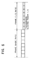
- Fig. 6 is a diagram for explaining the transmission electric power control in the second embodiment.
- a part of the Eb/Io measurement for the bit rates is common by using a situation that when the bit rate is decreased, the same symbol is repetitively transmitted.
- the reception base-band signal rs from the radio receiving unit (Rx) 20 (refer to Fig. 4) is supplied to the basic rate de-spreading unit 31.
- the signal is de-spread at the basic rate by the unit 31.
- a de-spread signal from the basic rate de-spreading unit 31 is supplied to the 1-symbol, 2-symbol, 4-symbol, and 8-symbol adding units 32, 33, 34, and 35, respectively. In each of the units, the number of symbols repeated depending upon the bit rate is added.
- the Eb/Io measuring units 36, 37, 38, and 39 execute the Eb/Io measurements for the symbols added by the 1-symbol adding unit 32 to 8-symbol adding unit 35 and output the resultant values to the maximum value detecting unit 16.
- the processes subsequent to that of the maximum value detecting unit 16 are substantially the same as those in the first embodiment explained with reference to Fig. 4.
- Various methods are known for measurement of the Eb/Io serving as an index of the reception quality.
- the CDMA in order to increase a communication capacity, it is normal to execute the operation at an extremely low Eb/Io value.
- a reception signal is inversely modulated to provide a carrier component and an interference component.
- the slot content mean value (or a gravity) of the inverse modulation signal as a carrier component (desired signal component) and a variance as an interference component the signal electric energy per bit Eb is obtained from a square value of the mean value, and the interference electric power per Hz Io is obtained from the variance.
- variable bit rate transmission As shown in Fig. 6, a first frame is transmitted at the basic rate (maximum bit rate) and a second frame is transmitted at a bit rate that is 1/2 of the basic rate.
- Each slot of the second frame in which the bit rate is 1/2 is transmitted by an electric power that is 1/2 as compared with that of a slot of the first frame transmitted at the basic rate.
- the transmission is continuously executed without turning ON/OFF the transmission in the frame or slot.
- a changed portion of the transmission electric power on a slot unit basis by the transmission electric power control is omitted.
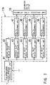
- Fig. 7 is a block diagram showing a construction of an Eb/Io calculating circuit in the third embodiment.
- an Eb/Io calculating circuit 11b has a de-spreading and inverse modulating unit 41 for de-spreading the base-band signal rd from the radio receiving unit (Rx) 20 and executing an inverse modulation to the signal rd by the reverse transmission data (r-rd) from the demodulating unit 18 in Fig. 4, thereby eliminating a modulation component; and a mean squared value unit 42 for calculating a mean squared value of the reception signal in which the modulation component was eliminated of the de-spreading and inverse modulating unit 41 in a slot interval.
- the Eb/Io calculating circuit 11b further has a whole slot mean value unit 43 for calculating a mean value of a whole slot interval; a 1/2 slot means value unit 44 for calculating a mean value of 1/2 slot interval; a 1/4 slot mean value unit 45 for calculating a mean value of 1/4 slot interval; and a 1/8 slot mean value unit 46 for calculating a mean value of 1/8 slot interval.
- the Eb/Io calculating circuit 11b also has an Eb/Io measuring unit 47 for outputting the Eb/Io value based on the mean squared value generated by the mean squared value unit 42 and the mean value of the whole slot interval from the whole slot mean value unit 43 to the maximum value detecting unit 16; and an Eb/Io measuring unit 48 for outputting the Eb/Io value based on the mean squared value generated by the mean squared value unit 42 and the mean value of the 1/2 slot interval from the 1/2 slot mean value unit 44 to the maximum value detecting unit 16.
- the Eb/Io calculating circuit 11b further has an Eb/Io measuring unit 49 for outputting the Eb/Io value based on the mean squared value generated by the mean squared value unit 42 and the mean value of the 1/4 slot interval from the 1/4 slot mean value unit 45 to the maximum value detecting unit 16; and an Eb/Io measuring unit 50 for outputting the Eb/Io value based on the mean squared value generated by the mean squared value unit 42 and t he mean value of the 1/8 slot interval from the 1/8 slot mean value unit 46 to the maximum value detecting unit 16.
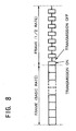
- Fig. 8 is a diagram for explaining the transmission electric power control in the operation of the third embodiment.
- the Eb/Io calculating circuit 11b transmits or receives only parts of the slots depending upon the bit rate and, particularly, sets the maximum bit rate to a basic rate, varies the bit rate to 1/2, 1/4, and 1/8 of the basic rate, and measures the Eb/Io values in the variable rate transmissions in which the intervals of the slot in which the transmission is ON are set to 1/2, 1/4, and 1/8 of one slot, respectively.
- the de-spreading and inverse modulating unit 41 de-spreads the reception base-band signal rs from the radio receiving unit (Rx) 20 and also inversely modulates the signal with the demodulation data rd, thereby eliminating the modulation component.
- a mean squared value of the reception signal with the modulation eliminated of the de-spreading and inverse modulating unit 41 is calculated in the slot interval by the mean squared value unit 42. The mean squared values are commonly extracted at all of the bit rates.
- the transmission ON interval includes the desired signal component and interference component
- only the interference component of the transmission OFF interval is included, so that the Eb/Io measurement can be executed with all of the reception signals (reception base-band signal rs) in the slot.
- the dispersion can be obtained as a difference between a mean squared value, namely, a value obtained by squaring samples, summing the squared value, and then dividing the summed value by the number of samples, and a square of the mean value, namely, a value of a sum obtained in such a manner that when the reception base-band signal rs is shown as a complex number in which a same phase component is set to a real number portion and an orthogonal component is set to an imaginary number portion, after a mean value of the complex number is obtained, a square of the real number portion and a square of the imaginary number are added.
- a mean squared value namely, a value obtained by squaring samples, summing the squared value, and then dividing the summed value by the number of samples
- a square of the mean value namely, a value of a sum obtained in such a manner that when the reception base-band signal rs is shown as a complex number in which a same phase component is
- the mean squared value it is a calculation common to all of the bit rates.
- the mean value since the calculation of only the portion in which the transmission is ON is executed, the interval in which the mean value is obtained depending upon the bit rate is different.
- Eb/Io(N)
- the reason why the square of the mean value is divided by N is that a desired signal is included in only the interval of 1/N of the slot and only the interference component is included in other intervals, namely, it is assumed that the electric power of the desired signal component is equal to 0.
- the mean squared value of the mean value of the signal after completion of the de-spreading -and inverse modulation is set to a value proportional to the reception signal electric energy per bit (Eb)
- the distribution is set to a value proportional to the interference electric power per Hz (Io)
- an estimate of the Eb/Io is calculated for every bit rate.
- the interference wave electric power per Hz (Io) is a value which doesn't depend on the bit rate but an estimated expression of the interference wave electric power (Io) per Hz is different depending on a bit rate that is assumed when Io is estimated from the reception signal.
- the variable bit rate transmitting system in which the interference wave electric power is sufficiently large as compared with the desired signal electric power and the transmission electric power is constant in one slot (for example, the variable bit rate transmitting method of changing the spreading factor depending upon the bit rate and also changing the transmission electric power in inverse proportion to the spreading factor), the estimate of the interference wave electric power that does not depend on the bit rate can be used.
- Eb measuring units 51, 52, 53 and 54 for estimating the reception signal electric energy Eb for all of the bit rates and an Io measuring unit 55 for estimating the interference wave electric power (Io) by a method which does not depend on the bit rate are provided.
- the maximum value detecting unit 16 obtains the maximum value of the reception signal electric energys Eb obtained for all bit rates.
- An Eb/Io calculating unit 56 calculates the Eb/Io from the obtained maximum value of Eb and Io estimated by the Io measuring unit 55.
- the comparing unit 17 compares the Eb/Io value with the target Eb/Io. As mentioned above, the reception quality can thus be estimated.
- variable rate CDMA transmission electric power controlling system of the invention since the maximum value of the Eb/Io values measured depending upon a plurality of bit rates obtained from the reception baseband signal is obtained and the transmission electric power control is executed, it is unnecessary to previously know the bit rate, so that it is possible to rapidly form the transmission electric power control bit rate for every slot serving as a unit of the transmission electric power control.
- the transmitting quality is not deteriorated, the spreading factor is changed depending upon the bit rates, and when it is applied to the variable rate transmitting method of changing the transmission electric power in inverse proportion to the spreading factor and transmitting and the variable rate transmission in which only parts of the slots are transmitted in correspondence to the bit rate, a high-precision transmitting electric power control can be executed.
- a transmission electric power controlling system has been explained as being applicable to a base station apparatus and a mobile terminal. It is to be noted, however, that the present invention claims not only the transmission electric power controlling system but also a base station apparatus and/or a mobile terminal itself adopting the transmission electric power controlling system. The present invention is applicable to a forward link and a reverse link in the same manner.
Landscapes
- Engineering & Computer Science (AREA)
- Quality & Reliability (AREA)
- Computer Networks & Wireless Communication (AREA)
- Signal Processing (AREA)
- Mobile Radio Communication Systems (AREA)
- Communication Control (AREA)
- Transmitters (AREA)
Applications Claiming Priority (3)
| Application Number | Priority Date | Filing Date | Title |
|---|---|---|---|
| JP16357797A JP3202658B2 (ja) | 1997-06-20 | 1997-06-20 | 可変レートcdma送信電力制御方式 |
| JP163577/97 | 1997-06-20 | ||
| JP16357797 | 1997-06-20 |
Publications (3)
| Publication Number | Publication Date |
|---|---|
| EP0886389A2 true EP0886389A2 (fr) | 1998-12-23 |
| EP0886389A3 EP0886389A3 (fr) | 2003-05-02 |
| EP0886389B1 EP0886389B1 (fr) | 2005-08-31 |
Family
ID=15776561
Family Applications (1)
| Application Number | Title | Priority Date | Filing Date |
|---|---|---|---|
| EP19980111370 Expired - Lifetime EP0886389B1 (fr) | 1997-06-20 | 1998-06-19 | Contrôle de puissance d'émission pour système de téléphone mobile à AMDC à débit variable |
Country Status (5)
| Country | Link |
|---|---|
| US (1) | US6414948B1 (fr) |
| EP (1) | EP0886389B1 (fr) |
| JP (1) | JP3202658B2 (fr) |
| KR (1) | KR100319995B1 (fr) |
| DE (1) | DE69831368T2 (fr) |
Cited By (7)
| Publication number | Priority date | Publication date | Assignee | Title |
|---|---|---|---|---|
| EP1037483A1 (fr) * | 1999-03-16 | 2000-09-20 | Alcatel | Méthode pour sélectionner dynamiquement une valeur paramétrique optimale pour un algorithme de contrôle de puissance dans un système de radiocommunication mobile |
| DE19913371A1 (de) * | 1999-03-24 | 2000-10-19 | Siemens Ag | Initiale Sendeleistungseinstellung für die Abwärtsrichtung von W-CDMA Funk-Kommunikationssystemen |
| EP1061668A1 (fr) * | 1999-06-16 | 2000-12-20 | Alcatel | Méthode pour améliorer les performances d'un système mobile de radiocommunication en utilisant un algorithme de commande de puissance |
| EP1113589A2 (fr) * | 1999-12-28 | 2001-07-04 | NTT DoCoMo, Inc. | Reglage de debit sur base du trafic et de la puissance d'émission |
| US7929723B2 (en) | 1997-01-13 | 2011-04-19 | Micro Ear Technology, Inc. | Portable system for programming hearing aids |
| US8300862B2 (en) | 2006-09-18 | 2012-10-30 | Starkey Kaboratories, Inc | Wireless interface for programming hearing assistance devices |
| US9344817B2 (en) | 2000-01-20 | 2016-05-17 | Starkey Laboratories, Inc. | Hearing aid systems |
Families Citing this family (36)
| Publication number | Priority date | Publication date | Assignee | Title |
|---|---|---|---|---|
| JP3267569B2 (ja) | 1998-11-27 | 2002-03-18 | 日本電気株式会社 | サーチャ制御方法とサーチャ制御装置及び無線通信装置 |
| JP3178442B2 (ja) | 1998-12-10 | 2001-06-18 | 日本電気株式会社 | 符号分割多重接続における回線速度制御システム |
| AU774602B2 (en) * | 1998-12-23 | 2004-07-01 | Nokia Inc. | A unified routing scheme for ad-hoc internetworking |
| US6249683B1 (en) * | 1999-04-08 | 2001-06-19 | Qualcomm Incorporated | Forward link power control of multiple data streams transmitted to a mobile station using a common power control channel |
| JP3374908B2 (ja) * | 1999-05-06 | 2003-02-10 | 日本電気株式会社 | 高速クローズトループ送信電力制御における基準値の更新方法 |
| JP2001016166A (ja) * | 1999-07-01 | 2001-01-19 | Matsushita Electric Ind Co Ltd | 送信電力制御方法および送受信装置 |
| US6496706B1 (en) * | 1999-07-23 | 2002-12-17 | Qualcomm Incorporated | Method and system for transmit gating in a wireless communication system |
| US6603752B1 (en) * | 1999-07-29 | 2003-08-05 | Ahmed Saifuddin | Method and system for controlling transmission energy in a variable rate gated communication system |
| DE50013196D1 (de) * | 1999-08-10 | 2006-08-31 | Nanotron Technologies Gmbh | Übertragungsverfahren mit senderseitiger frequenz- und zeitspreizung |
| US20030156624A1 (en) * | 2002-02-08 | 2003-08-21 | Koslar | Signal transmission method with frequency and time spreading |
| US6621808B1 (en) * | 1999-08-13 | 2003-09-16 | International Business Machines Corporation | Adaptive power control based on a rake receiver configuration in wideband CDMA cellular systems (WCDMA) and methods of operation |
| JP2001077724A (ja) | 1999-09-07 | 2001-03-23 | Nec Corp | 送信電力制御装置および送信電力制御方法 |
| US7170928B1 (en) * | 1999-09-09 | 2007-01-30 | Nokia Corporation | Determination of data rate, based on power spectral density estimates |
| JP2001203668A (ja) * | 2000-01-18 | 2001-07-27 | Matsushita Electric Ind Co Ltd | 干渉信号除去装置および干渉信号除去方法 |
| JP4385489B2 (ja) * | 2000-03-03 | 2009-12-16 | ソニー株式会社 | 通信システム、通信方法及び通信装置 |
| FR2810177B1 (fr) * | 2000-06-13 | 2005-05-06 | Cit Alcatel | Procede pour le controle de puissance d'emission dans un systeme de radiocommunications mobiles |
| JP2002009692A (ja) | 2000-06-23 | 2002-01-11 | Matsushita Electric Ind Co Ltd | データ伝送装置及びデータ伝送方法 |
| JP3583353B2 (ja) * | 2000-07-03 | 2004-11-04 | 松下電器産業株式会社 | 通信端末装置および基地局装置 |
| US6963752B1 (en) * | 2000-09-18 | 2005-11-08 | Telefonaktiebolaget L M Ericsson (Publ) | Method and apparatus for setting transmit power control command energy |
| KR100396778B1 (ko) * | 2001-06-25 | 2003-09-02 | 엘지전자 주식회사 | 이동통신 단말기의 전력 제어방법 |
| CN100571058C (zh) * | 2001-07-24 | 2009-12-16 | 株式会社Ntt都科摩 | 移动通信系统发送功率控制装置与方法 |
| AU2002361468A1 (en) * | 2001-08-14 | 2003-03-18 | The Government Of The United States Of America As Represented By The Secretary Of Health And Human S | Method for rapid generation of mature dendritic cells |
| JP3577021B2 (ja) * | 2001-09-12 | 2004-10-13 | 埼玉日本電気株式会社 | 移動局および移動局における電界状態判定方法 |
| JP4606668B2 (ja) * | 2001-09-17 | 2011-01-05 | Okiセミコンダクタ株式会社 | 電力制御回路及び電力制御方法 |
| US6717931B2 (en) * | 2002-01-02 | 2004-04-06 | Nokia Corporation | Adaptive spreading factor based on power control |
| JP2003218778A (ja) * | 2002-01-24 | 2003-07-31 | Nec Corp | 無線送受信装置及び無線通信システム |
| US7209517B2 (en) * | 2002-03-04 | 2007-04-24 | Qualcomm Incorporated | Method and apparatus for estimating a maximum rate of data and for estimating power required for transmission of data at a rate of data in a communication system |
| US7751843B2 (en) | 2002-07-29 | 2010-07-06 | Qualcomm Incorporated | Reducing interference with a multiple format channel in a communication system |
| JP4071598B2 (ja) * | 2002-10-04 | 2008-04-02 | 株式会社エヌ・ティ・ティ・ドコモ | 移動通信システム、移動通信方法、及びこれらに用いて好適な無線局 |
| TWI330949B (en) * | 2002-11-20 | 2010-09-21 | Interdigital Tech Corp | Receiver and wireless transmit receive unit |
| JP4709276B2 (ja) * | 2005-04-22 | 2011-06-22 | テレフオンアクチーボラゲット エル エム エリクソン(パブル) | 電力制御に関する方法および装置 |
| WO2007083636A1 (fr) * | 2006-01-17 | 2007-07-26 | Matsushita Electric Industrial Co., Ltd. | Dispositif de transmission radio et méthode de transmission radio |
| US8670355B1 (en) * | 2007-10-18 | 2014-03-11 | At&T Mobility Ii Llc | System and method for network based hearing aid compatible mode selection |
| US8218493B2 (en) * | 2008-09-08 | 2012-07-10 | Wisconsin Alumni Research Foundation | System and method for interference mitigation in wireless networks |
| US7702290B1 (en) * | 2009-04-08 | 2010-04-20 | On-Ramp Wirless, Inc. | Dynamic energy control |
| US20110263212A1 (en) * | 2010-04-26 | 2011-10-27 | Chih-Hao Yeh | Wireless device and controlling method of wireless device |
Citations (1)
| Publication number | Priority date | Publication date | Assignee | Title |
|---|---|---|---|---|
| WO1996004718A1 (fr) * | 1994-07-29 | 1996-02-15 | Qualcomm Incorporated | Procede et appareil pour reguler la puissance dans un systeme de communication a vitesse variable |
Family Cites Families (12)
| Publication number | Priority date | Publication date | Assignee | Title |
|---|---|---|---|---|
| US5103459B1 (en) | 1990-06-25 | 1999-07-06 | Qualcomm Inc | System and method for generating signal waveforms in a cdma cellular telephone system |
| JPH05102943A (ja) | 1991-10-04 | 1993-04-23 | Nippon Telegr & Teleph Corp <Ntt> | スペクトル拡散伝送方式 |
| JPH06209274A (ja) | 1993-01-11 | 1994-07-26 | Oki Electric Ind Co Ltd | 電力制御装置 |
| JP3148071B2 (ja) | 1994-04-01 | 2001-03-19 | 沖電気工業株式会社 | 電力制御装置 |
| JP2701761B2 (ja) | 1994-11-02 | 1998-01-21 | 日本電気株式会社 | 送信ビットレート判別方法及び装置 |
| US5629934A (en) * | 1995-06-30 | 1997-05-13 | Motorola, Inc. | Power control for CDMA communication systems |
| KR970013834A (ko) * | 1995-08-23 | 1997-03-29 | 사와무라 시코우 | 전송속도 추정장치(A computing apparatus of transmission rate) |
| JPH09327059A (ja) * | 1996-06-07 | 1997-12-16 | N T T Ido Tsushinmo Kk | Cdma移動通信システムにおけるセル選択方法およびその基地局装置と移動局装置 |
| JP3818702B2 (ja) * | 1996-08-07 | 2006-09-06 | 松下電器産業株式会社 | Cdma無線伝送システム並びに該システムにおいて用いられる送信電力制御装置および送信電力制御用測定装置 |
| US5974042A (en) * | 1997-02-28 | 1999-10-26 | Motorola, Inc. | Service detection circuit and method |
| US6094428A (en) * | 1997-04-30 | 2000-07-25 | Motorola, Inc. | Method and apparatus for transmission and reception of a transmission rate in a CDMA communication system |
| KR100243213B1 (ko) * | 1997-06-14 | 2000-02-01 | 윤종용 | 제로상태평가량을이용한비터비복호데이터의품질평가장치 |
-
1997
- 1997-06-20 JP JP16357797A patent/JP3202658B2/ja not_active Expired - Lifetime
-
1998
- 1998-06-18 US US09/099,593 patent/US6414948B1/en not_active Expired - Lifetime
- 1998-06-19 EP EP19980111370 patent/EP0886389B1/fr not_active Expired - Lifetime
- 1998-06-19 DE DE1998631368 patent/DE69831368T2/de not_active Expired - Lifetime
- 1998-06-20 KR KR1019980023235A patent/KR100319995B1/ko not_active IP Right Cessation
Patent Citations (1)
| Publication number | Priority date | Publication date | Assignee | Title |
|---|---|---|---|---|
| WO1996004718A1 (fr) * | 1994-07-29 | 1996-02-15 | Qualcomm Incorporated | Procede et appareil pour reguler la puissance dans un systeme de communication a vitesse variable |
Non-Patent Citations (1)
| Title |
|---|
| SAMPATH A ET AL: "Power control and resource management for a multimedia CDMA wireless system" SIXTH IEEE INTERNATIONAL SYMPOSIUM ON PERSONAL, INDOOR AND MOBILE RADIO COMMUNICATIONS. PIMRC'95. WIRELESS: MERGING ONTO THE INFORMATION SUPERHIGHWAY (CAT. NO.95TH8135), PROCEEDINGS OF 6TH INTERNATIONAL SYMPOSIUM ON PERSONAL, INDOOR AND MOBILE RADIO , pages 21-25 vol.1, XP002157913 1995, New York, NY, USA, IEEE, USA ISBN: 0-7803-3002-1 * |
Cited By (12)
| Publication number | Priority date | Publication date | Assignee | Title |
|---|---|---|---|---|
| US7929723B2 (en) | 1997-01-13 | 2011-04-19 | Micro Ear Technology, Inc. | Portable system for programming hearing aids |
| EP1037483A1 (fr) * | 1999-03-16 | 2000-09-20 | Alcatel | Méthode pour sélectionner dynamiquement une valeur paramétrique optimale pour un algorithme de contrôle de puissance dans un système de radiocommunication mobile |
| DE19913371A1 (de) * | 1999-03-24 | 2000-10-19 | Siemens Ag | Initiale Sendeleistungseinstellung für die Abwärtsrichtung von W-CDMA Funk-Kommunikationssystemen |
| EP1061668A1 (fr) * | 1999-06-16 | 2000-12-20 | Alcatel | Méthode pour améliorer les performances d'un système mobile de radiocommunication en utilisant un algorithme de commande de puissance |
| US6337973B1 (en) | 1999-06-16 | 2002-01-08 | Alcatel | Method for improving performances of a mobile radiocommunication system using a power control algorithm |
| US7477912B2 (en) | 1999-06-16 | 2009-01-13 | Alcatel | Method for improving performances of a mobile radiocommunication system using a power control algorithm |
| EP1113589A2 (fr) * | 1999-12-28 | 2001-07-04 | NTT DoCoMo, Inc. | Reglage de debit sur base du trafic et de la puissance d'émission |
| EP1113589A3 (fr) * | 1999-12-28 | 2003-10-15 | NTT DoCoMo, Inc. | Reglage de debit sur base du trafic et de la puissance d'émission |
| US6909905B2 (en) | 1999-12-28 | 2005-06-21 | Ntt Docomo, Inc. | Mobile communications control including change of bit rate based on traffic and transmit power |
| US9344817B2 (en) | 2000-01-20 | 2016-05-17 | Starkey Laboratories, Inc. | Hearing aid systems |
| US9357317B2 (en) | 2000-01-20 | 2016-05-31 | Starkey Laboratories, Inc. | Hearing aid systems |
| US8300862B2 (en) | 2006-09-18 | 2012-10-30 | Starkey Kaboratories, Inc | Wireless interface for programming hearing assistance devices |
Also Published As
| Publication number | Publication date |
|---|---|
| EP0886389A3 (fr) | 2003-05-02 |
| JPH1117646A (ja) | 1999-01-22 |
| KR19990007171A (ko) | 1999-01-25 |
| US6414948B1 (en) | 2002-07-02 |
| EP0886389B1 (fr) | 2005-08-31 |
| KR100319995B1 (ko) | 2002-04-22 |
| DE69831368D1 (de) | 2005-10-06 |
| DE69831368T2 (de) | 2006-02-09 |
| JP3202658B2 (ja) | 2001-08-27 |
Similar Documents
| Publication | Publication Date | Title |
|---|---|---|
| EP0886389B1 (fr) | Contrôle de puissance d'émission pour système de téléphone mobile à AMDC à débit variable | |
| JP2785804B2 (ja) | 移動通信システム | |
| CA2323099C (fr) | Correction de mesures du rapport signal-interferences | |
| CA2158270C (fr) | Methode et appareil servant a reduire l'autoparasitage dans les systemes de communication | |
| KR100493079B1 (ko) | 고속 순방향 패킷 접속 방식을 사용하는 광대역 부호 분할다중 접속 통신 시스템에서 순방향 채널 품질을 보고하는장치 및 방법 | |
| US7236537B2 (en) | Method and radio system for digital signal transmission | |
| EP1358721B1 (fr) | Procede et systeme de commande de la puissance de transmission d'appareil dans un reseau de communication sans fil | |
| US7058363B2 (en) | Data transmission method and radio system | |
| US6507603B1 (en) | CDMA receiver | |
| CN101199145B (zh) | 共享控制信道检测策略 | |
| KR20050114631A (ko) | 소프트-핸드오프 동안 전력 제어 명령의 신뢰성 결정 및결합 | |
| JPH09252266A (ja) | Cdmaセルラ無線伝送装置 | |
| US20030072253A1 (en) | Communication terminal apparatus and demodulation method | |
| US20050174968A1 (en) | Apparatus and Method for Transmission | |
| KR100934832B1 (ko) | 이동체 통신 시스템, 이동체 통신 시스템에 있어서의 이동단말, 그 제어 프로그램 및 이동체 통신 시스템에 있어서의동기 확립 판정 방법 | |
| EP1065802B1 (fr) | Procédé et dispositif de commande de la puissance de transmission en mésurant l' Eb/No de la combinaison de signaux pondérés | |
| KR20030017950A (ko) | 고속 순방향 패킷 접속 방식을 사용하는 통신 시스템에서역방향 전송 전력을 제어하는 장치 및 방법 | |
| KR100354165B1 (ko) | 고속 순방향 전력제어 방법 | |
| KR20040016330A (ko) | 광대역 시분할 듀플렉싱 고속 순방향 패킷 접속 방식을사용하는 이동 통신시스템에서 고속 공통 정보 채널 송신전력 제어 장치 및 방법 | |
| KR100866759B1 (ko) | Td-scdma 시스템에서의 전력 제어 방법 및 이에적용되는 장치 | |
| JP2013247500A (ja) | 無線通信装置及び電力制御方法 | |
| KR20010066567A (ko) | 디지탈 통신 시스템의 순방향 전력제어를 위한 snr평가 장치 |
Legal Events
| Date | Code | Title | Description |
|---|---|---|---|
| PUAI | Public reference made under article 153(3) epc to a published international application that has entered the european phase |
Free format text: ORIGINAL CODE: 0009012 |
|
| AK | Designated contracting states |
Kind code of ref document: A2 Designated state(s): AT BE CH CY DE DK ES FI FR GB GR IE IT LI LU MC NL PT SE |
|
| AX | Request for extension of the european patent |
Free format text: AL;LT;LV;MK;RO;SI |
|
| PUAL | Search report despatched |
Free format text: ORIGINAL CODE: 0009013 |
|
| AK | Designated contracting states |
Designated state(s): AT BE CH CY DE DK ES FI FR GB GR IE IT LI LU MC NL PT SE |
|
| AX | Request for extension of the european patent |
Extension state: AL LT LV MK RO SI |
|
| 17P | Request for examination filed |
Effective date: 20030319 |
|
| AKX | Designation fees paid |
Designated state(s): DE GB IT |
|
| 17Q | First examination report despatched |
Effective date: 20040726 |
|
| GRAP | Despatch of communication of intention to grant a patent |
Free format text: ORIGINAL CODE: EPIDOSNIGR1 |
|
| GRAS | Grant fee paid |
Free format text: ORIGINAL CODE: EPIDOSNIGR3 |
|
| GRAA | (expected) grant |
Free format text: ORIGINAL CODE: 0009210 |
|
| AK | Designated contracting states |
Kind code of ref document: B1 Designated state(s): DE GB IT |
|
| REG | Reference to a national code |
Ref country code: GB Ref legal event code: FG4D |
|
| REF | Corresponds to: |
Ref document number: 69831368 Country of ref document: DE Date of ref document: 20051006 Kind code of ref document: P |
|
| PLBE | No opposition filed within time limit |
Free format text: ORIGINAL CODE: 0009261 |
|
| STAA | Information on the status of an ep patent application or granted ep patent |
Free format text: STATUS: NO OPPOSITION FILED WITHIN TIME LIMIT |
|
| 26N | No opposition filed |
Effective date: 20060601 |
|
| PGFP | Annual fee paid to national office [announced via postgrant information from national office to epo] |
Ref country code: GB Payment date: 20170614 Year of fee payment: 20 Ref country code: DE Payment date: 20170613 Year of fee payment: 20 |
|
| PGFP | Annual fee paid to national office [announced via postgrant information from national office to epo] |
Ref country code: IT Payment date: 20170619 Year of fee payment: 20 |
|
| REG | Reference to a national code |
Ref country code: DE Ref legal event code: R071 Ref document number: 69831368 Country of ref document: DE |
|
| REG | Reference to a national code |
Ref country code: GB Ref legal event code: PE20 Expiry date: 20180618 |
|
| PG25 | Lapsed in a contracting state [announced via postgrant information from national office to epo] |
Ref country code: GB Free format text: LAPSE BECAUSE OF EXPIRATION OF PROTECTION Effective date: 20180618 |