BACKGROUND OF THE INVENTION
Field of the Invention
The present invention relates to a white optical pulse source
produced by injecting pump pulses into a waveguided nonlinear optical
medium to generate white pulses having a flatly broadened spectrum, and
applications of the white pulse source to other optical devices.
This application is based on patent application Nos. Hei 9-161603,
Hei 9-274593, Hei 10-81176 and Hei 10-81177 filed in Japan, the contents of
which are incorporated herein by reference.
Description of the Related Art
As shown in Figure 23, an optical pulse source is comprise by an
optical pump pulse source and a waveguided nonlinear optical medium. A
pump pulse propagating in the waveguided nonlinear optical medium
induces a third order nonlinear optical effect and generates white pulse of a
broad bandwidth. The propagation distance from the input end of the
waveguided nonlinear optical medium is designated by z such that at the
input end z = 0 and at the output end z = L.
A reference 1 (a Japanese Patent Application, First Publication, Hei
8-234249, "Coherent white pulse source") disclosed a white pulse source
using a single-mode optical fiber as the nonlinear optical medium, and
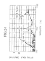
reported a production of white pulses having an excellent spectral flatness
over a wide range of wavelengths as illustrated in Figure 24. Based on a
supposition that such white pulses were produced because of the choice of a
low dispersion slope of the waveguided nonlinear optical medium, values of
the dispersion slope which is defined as the first derivative of chromatic
dispersion with respect to wavelength and magnitudes of dispersion are
specified. Figure 24 shows the spectrum of the pump pulse also.
The reference 1 also disclosed that the bandwidth of the white pulse
increases by using a waveguided nonlinear optical medium whose chromatic
dispersion decreased with propagation distance z.
This effect is also shown in reference 2 (Okuno et. al., "Study about
optical fibers for generating supercontinuum pulses with high efficiency",
National Convention Record-The Institute of Electronics Information and
Communication Engineers, SB-13-6, 1997). As is shown in Figure 25, by
altering the chromatic dispersion at the center wavelength of the pump
pulses λ 0 from positive at the input end (z=0) to negative at the output end
(z=L), while suppressing the dispersion slope to be low, broadband white
pulses are generated. The spectrum of the white pulse produced by the white
pulse source in reference 2 is shown in Figure 26.
In reference 3 (Tamura et. al., "Generation of 10 GHz pulse trains at
16 wavelengths by spectrally slicing a high power femtosecond source",
Electronics Letters, vol. 32, no. 18, pp. 1691-1693, 1996), white pulses are
generated by a device to pump a waveguided nonlinear optical medium with
optical gain (rare-earth doped optical fiber). This device is able to generate
white pulses even when the power of pump pulses is low or the length of the
waveguided nonlinear optical medium is short.
Here, it should be reminded that, for communication or
instrumentation purpose, it is necessary to be able to reproduce white pulses
that are not only broadband but remain flat, i.e., a constant optical power
output over a wide range of wavelengths.
The conventional techniques disclosed in references 1 and 2 specify
only the first order term (dispersion slope) in the chromatic dispersion to
wavelengths in the waveguided nonlinear optical medium. In reference 3,
the results are associated mostly with doping effects in the waveguided
nonlinear optical medium, and the manner of chromatic dispersion reduction
is only minimally specified. Therefore, at the present time, a white pulse
such as the one illustrated by the special curve in Figure 24 that satisfy
both requirements of wide band-width and spectral flattening have not been
reproduced in practice.
Further, conventional white optical pulse sources have not been able
to generate white pulses having low noise over a wide spectral range,
because of the lack of knowledge regarding the mechanism of noise in white
pulse generation process.
Further, because it has not been possible to generate low-noise white
pulses, a pulse source that combines a white pulse source with a wavelength
filter to produce low-noise optical pulses could not be realized also.
SUMMARY OF THE INVENTION
It is an object of the present invention to provide a white pulse source
to produce white pulses having a equalized spectrum over a wide spectral
range based on the mechanism of white pulse generation.
The object has been achieved in a white pulse source comprised by a
pump pulse source for generating optical pump pulses having a center
wavelength λ 0 and a waveguided nonlinear optical medium with a length of
L, wherein the waveguided nonlinear optical medium is characterized by two
properties: a first property being that chromatic dispersion D(λ 0,z) at the
wavelength of pump pulses λ 0 in ps/nm/km is positive at an input end of
the waveguided nonlinear optical medium, where z=0, and decreases
towards an output; and a second property being that there are two zero-dispersion
wavelengths λ 1(z) and λ 2(z), where D(λ 1(z), z) = D(λ 2(z), z) =
0, within a range of propagation distance given by L1 ≦ z ≦ L, where 0 ≦
L1 < L, that chromatic dispersion D(λ, z) has a local maximum D(λ p(z), z)
at a peak wavelength λp(z) and that the local maximum D(λp(z), z) has
positive values.
White pulses generate via a two stage process: a spectral broadening
stage caused by adiabatic soliton compression; and a rectangular-shape
forming stage caused by soliton changing into dispersive waves. The result is
a generation of a white pulse spectrum, showing flatness over a wide range of
wavelength.
Another object of the present invention is to provide a stable-output
white pulse source to generate white pulses having stable output power and
low noise characteristics.
The object has been achieved in a white pulse source, having a pump
pulse generating section for producing pump pulses and a waveguided
nonlinear optical medium for generating white pulses by being injected with
the pump pulses, comprising a power stabilization section for controlling the
optical power of pump pulses to be input into the waveguided nonlinear
optical medium by reducing a noise component according to a relation of
pump pulse power to noise coefficients generated in the course of a white
pulse generation.
Accordingly, the white pulse source of the present invention has been
applied to produce white pulses having low noise and stable output power.
Another object is to provide a low-noise optical pulse source to
produce optical pulses having extremely low noise using the white pulse
source of the present invention.
The object has been achieved in an optical pulse source, having a
pump pulse generating section for producing pump pulses, a wave guided
nonlinear optical medium for generating white pulses by being injected with
the pump pulses, and a wavelength filter for filtering the white pulses to
produce an optical pulse having a specific wavelength, the optical pulse
source comprising a noise reducing section for controlling the optical power
of pump pulses to be input into the waveguided nonlinear optical medium by
reducing a noise component in the specific wavelength according to a relation
of pump pulse power to noise coefficients generated in the course of a white
pulse generation.
Accordingly, it is possible to generate low noise optical pulses that
are not affected by power fluctuations contained in the pump pulse.
BRIEF DESCRIPTION OF THE DRAWINGS
Figure 1 is a graph showing the first chromatic dispersion
characteristic of a waveguided nonlinear optical medium with respect to
wavelength for use in a equalized-output white optical pulse source.
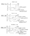
Figures 2A∼2C are graphs showing a refractive index profiles of the
waveguided nonlinear optical medium.
Figure 3 is a graph showing a spectrum of pump pulses input into the
waveguided nonlinear optical medium.
Figure 4 is a graph showing a spectrum of white pulses generated by
the waveguided nonlinear optical medium having the first chromatic
dispersion characteristics shown in Figure 1.
Figure 5 is an example of the output spectrum from a waveguided
noNlinear optical medium whose chromatic dispersion has two zero-dispersion
wavelengths but does not decrease with propagation distance.
Figure 6 is a graph showing how a white pulse spectrum evolves
along a waveguided nonlinear optical medium having the first chromatic
dispersion characteristics shown in Figure 1.
Figure 7 is a graph showing an example of the dependence of the
spectral width of the white pulse on the effective medium length L0.
Figure 8 is a graph showing an example of the relation of the
threshold value Lth of the effective medium length L0 for generating white
pulses to the peak power of the pump pulses.
Figure 9 is a graph showing an example of the dependence of the
spectral width of the white pulse on chromatic dispersion D(λ 0, 0) at the
input end of the waveguided nonlinear optical medium.
Figure 10 is an example of the dependence of spectral width of the
white pulse on the pulse width of the pump pulse.
Figure 11 is an example of the dependence of the spectral width of
the white pulse on the pump pulse width, in which chromatic dispersion D(λ
0, 0) is a parameter.
Figure 12 is a graph showing a second chromatic dispersion
characteristic of a waveguided nonlinear optical medium with respect to
wavelength for use in a equalized-output white optical pulse source.
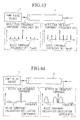
Figures 13A∼13C are graphs showing a spectra of white pulses
generated by the waveguided nonlinear optical medium having the
chromatic dispersion characteristics shown in Figure 12 for different
wavelength difference Λ.
Figure 14 is a graph showing a third chromatic dispersion
characteristic of a waveguided nonlinear optical medium with respect to
wavelength for use in a equalized-output white optical pulse source.
Figure 15 is a graph showing a spectrum of white pulses generated
by the waveguided nonlinear optical medium having the chromatic
dispersion characteristics shown in Figure 14.
Figure 16 is a schematic configuration of a equalized-output white
pulse source in Embodiment 2.
Figure 17 is an example of a white pulse spectrum produced from a
equalized-output white pulse source in Embodiment 2.
Figure 18 is a schematic configuration of an equalized-output white
pulse source in Embodiment 3.
Figure 19 is a graph showing an example of the dependence of the
white pulse spectral width on the effective medium length L0 of the
waveguided nonlinear optical medium with gain.
Figure 20 is a schematic configuration of an equalized-output white
pulse source in Embodiment 4.
Figure 21 is a schematic configuration of an equalized-output white
pulse source in Embodiment 5.
Figure 22 is a schematic configuration of an equalized-output white
pulse source in Embodiment 6.
Figure 23 is a schematic configuration of a conventional white pulse
source.
Figure 24 is an example of a spectrum produced by a white pulse
source cited in reference 1.
Figure 25 is a graph showing the chromatic dispersion
characteristics of the waveguided nonlinear optical medium used in the
white pulse source cited in reference 2.
Figure 26 is an example of a spectrum produced by a white pulse
source cited in reference 2.
Figure 27 is a map showing a contour curves of spectral widths of
output from the waveguided nonlinear optical medium with respect to
chromatic dispersion at the input end D(λ0, 0) on the vertical axis and
effective medium lengths L0 on the horizontal axis.
Figure 28 is a map showing a contour curves of spectral widths of
output from the waveguided nonlinear optical medium with Raman effect
with respect to chromatic dispersion at the input end D(λ0, 0) on the
vertical axis and effective medium lengths L0 on the horizontal axis.
Figure 29 is a spectrum of white pulses generated from the
waveguided nonlinear optical medium designed according to a third relation
of wavelengths to chromatic dispersion.
Figure 30 is a block diagram of the basic configuration of the stable-output
white pulse source of the present invention.
Figure 31 is a block diagram of a configuration of the stable-output
white pulse source in Embodiment 1 in Section 2.
Figure 32 is a schematic configuration of the experimental setup for
measuring the noise coefficient.
Figure 33 is an example of the measurement results of the noise
coefficient depending on the peak power of pump pulses for different
wavelengths.
Figures 34A and 34B are a block diagrams of the stable-output white
pulse source in Embodiment 2 in Section 2.
Figure 35 is a block diagram of the stable-output white pulse source
in Embodiment 3 in Section 2.
Figure 36 is a block diagram of the stable-output white pulse source
in Embodiment 4 in Section 2.
Figure 37 is a block diagram of the stable-output white pulse source
in Embodiment 5 in Section 2.
Figure 38 is a block diagram of the stable-output white pulse source
in Embodiment 6 in Section 2.
Figure 39 is a block diagram of the stable-output white pulse source
in Embodiment 7 in Section 2.
Figure 40 is a block diagram of the stable-output white pulse source
in Embodiment 8 in Section 2.
Figure 41 is a block diagram of the stable-output white pulse source
in Embodiment 9 in Section 2.
Figure 42 is a block diagram of the stable-output white pulse source
in Embodiment 10 in Section 2.
Figure 43 is an example of noise components in a harmonically
mode-locked laser as a pump pulse source.
Figure 44 is another example of low-frequency noise components in a
mode-locked laser as a pump pulse source.
Figure 45 is a block diagram of the stable-output white pulse source
in Embodiment 11 in Section 2.
Figure 46 is a block diagram of a basic configuration of the low-noise
pulse source of the present invention.
Figure 47 is a block diagram of a configuration of the low-noise pulse
source of the present invention in Embodiment 1 in Section 3.
Figure 48 illustrates the dependence of intensity fluctuation in
optical pulses filtered from white pulses for different noise coefficients.
Figures 49A, 49B are block diagrams of the low-noise pulse source of
Embodiment 2 in Section 3.
Figure 50 is a block diagram of the low-noise pulse source of
Embodiment 3 in Section 3.
Figure 51 is a block diagram of the low-noise pulse source of
Embodiment 4 in Section 3.
Figure 52 is a block diagram of the low-noise pulse source of
Embodiment 5 in Section 3.
Figure 53 is a block diagram of the low-noise pulse source of
Embodiment 6 in Section 3.
Figure 54 is a block diagram of the low-noise pulse source of
Embodiment 7 in Section 3.
Figure 55 is a block diagram of the low-noise pulse source of
Embodiment 8 in Section 3
Figure 56 is a block diagram of the stable-output white pulse source
in Embodiment 9 in Section 3.
DESCRIPTION OF THE PREFERRED EMBODIMENTS
In the following, the white pulse source for generating white pulses
by inputting pump pluses into the waveguided nonlinear optical medium will
be presented under the following three sections dealing with white pulse
sources of respective properties as defined below:
Section 1 Equalized-output White Pulse Sources and Evolution of White
Pulses
First, some features of the white pulse sources in this section will be
explained.
The white pulse sources in this section are comprised by a pump
pulse source for generating pump pulses having a center wavelength λ 0,
and the waveguided nonlinear optical medium (shortened to optical medium
hereinbelow) having a length of L for generating white pulses by being
injected with the pump pulses.
Chromatic dispersion D(λ 0, z), in units of ps/nm/km, at the center
wavelength λ 0 of the pump pulses in the optical medium at the input end (z
= 0) is positive and decreases in the propagation direction of the pump
pulses.
Further, within the propagation distance z of the pump pulses, where
L1 ≦ z ≦ L and 0 ≦ L1 < L, the chromatic dispersion D(λ, z) has a
maximum value of D(λp(z), z) at a peak wavelength λp(z), and within a
range of propagation distance z where D(λp(z), z) are positive, chromatic
dispersion is zero (ps/nm/km) at two wavelengths λ 1(z) and λ 2(z).
Next, generation and evolution of the white pulses in the white pulse
source will be explained.
A white pulse evolves through a two-stage process: a spectral
broadening stage due to adiabatic soliton compression and a stage of
rectangular shaping and output power flattening caused by solitons
changing into dispersive waves.
A pump pulse injected into the optical meclium undergoes spectral
broadening in the stage of adiabatic soliton compression within the
propagation distance z where the chromatic dispersion D(λ 0, z) of the
optical medium is positive (anomalous dispersion) at the center wavelength
λ 0. As the chromatic dispersion D(λ 0, z) of the optical medium decreases
with propagation distance z, and as the two zero-dispersion wavelengths, λ
1(z) and λ 2(z), approach the center wavelength λ 0 of the pump pulse,
although the both edges of the spectrum of the pulse being compressed enter
into the negative (normal dispersion) dispersion region, the pulse being
compressed as a whole retains soliton characteristics during spectral
broadening stage.
Further, as the chromatic dispersion D(λ 0, z) decreases with
increasing propagation distance z, soliton characteristics begin to be lost
from the both edges of the spectrum towards the pump wavelength λ 0 and
the pulse being compressed make transition from soliton pulse to a
dispersive wave. Accordingly, the spectrum stops broadening at the
breakdown points where the both edges of the spectrum begins to change to a
dispersive wave. On the other hand, in the regions close to the pump
wavelength λ 0 where the chromatic dispersion is still positive (anomalous
dispersion), the spectrum still continues to broaden so that optical energy
accumulates at the breakdown points to evolve into a rectangular spectral
shape. As the two zero-dispersion wavelengths approach the pump
wavelength λ 0, the both break down wavelengths also come near to the
pump wavelength λ 0 to result in a flattened spectrum.
Figure 6 illustrates how a white pulse spectrum evolves with
propagation distance z. The zero-dispersion wavelengths are indicated by
broken lines in Figure 6, and, at the propagation distance L0, the two zero-dispersion
wavelengths become coincident with the pump wavelength λ 0.
In Figure 6, the spectrums of the pump pulses are indicated by (a) at the
input end of the optical medium. As the two zero-dispersion wavelengths
approaches the pump pulse wavelength, the spectrum progressively changes
to a rectangular shape and, at the output end, a flattened spectrum is
obtained as is shown in (e).
In the following, the white pulse source having the features described
above will be described in more detail.
S1E1 Embodiment 1 in Section 1
The first embodiment of the white pulse source is comprised by a
pump pulse source similar to the one shown in Figure 23 and a waveguided
nonlinear optical medium (shortened to optical medium hereinbelow).
However, the optical medium to be used in the white pulse source in the
present invention is distinguished by a special characteristic of a chromatic
dispersion with respect to wavelength and distance from the input end.
S1E1-1. A first characteristic of a chromatic dispersion
Figure 1 illustrates a first characteristic of a chromatic dispersion
with respect to wavelength and distance in the optical medium to be used as
a white pulse source. In the graph, the vertical axis and the horizontal axis
represent chromatic dispersion in ps/nm/km and wavelength in nm.
Chromatic dispersion D(λ 0, z) at the center wavelength λ0 of pump
pulses in the optical medium is positive at the input end (z = 0), and
decreases towards the output end.
Further, chromatic dispersion D(λ, z) shows a maximum value D(λ
p(z), z) at a wavelength λ p(z), and in the vicinity of the peak wavelength λ
p(z), the graph can be approximated by a quadratic function. In Figure 1,
although it is indicated that λ 0 is set equal to λ p(z), the two wavelengths
λ 0 and λ p(z) do not necessarily have to be equal, such that some difference
Λ in wavelength can be allowed. Also, chromatic dispersion D(λ, z)
decreases from positive value to negative value with the propagation
distance z in the optical medium. These two features will be further
explained later.
Within the propagation distance in which the maximum value D(λ
p(z), z) is positive, chromatic dispersion D(λ, z) has two zero-dispersion
wavelengths λ 1(z) and λ 2(z), where λ 1(z) < λ 2(z). In other words, the
chromatic dispersion D(λ, z) is more than zero ps/nm/km (anomalous
dispersion) when a wavelength λ is greater than λ 1(z) and less than λ
2(z), and becomes less than zero ps/nm/km (normal dispersion) when a
wavelength λ is less than λ 1(z) or more than λ 2(z). These two
wavelengths λ 1(z) and λ 2(z) approach towards each other as the
chromatic dispersion D(λ p(z), z) decreases. Also, these two wavelengths λ
1(z) and λ 2(z) vanish when the maximum value D(λ p(z), z) become
negative.
As discussed above, the characteristic of a chromatic dispersion with
respect to wavelength and distance in the optical medium for use in the
white pulse source of the present invention is characterized by: (1) the
chromatic dispersion D(λ 0,z) at the pump wavelength λ0 decreases from a
positive value to negative value with propagation distance z, and also (2)
chromatic dispersion D(λ 0, z) has a maximum value D(λ p (z), z) and within
the range of propagation clistance z where the maximum value is positive,
there are two zero-dispersion wavelengths λ 1(z) and λ 2(z).
Such characteristics of the chromatic dispersion discussed in the
above paragraph can be realized in a double-clad, triple-clad or quadruple-clad
waveguide having a refractive index profile such as those illustrated in
Figures 2A∼2C. In the double-clad waveguide, average refractive indexes,
n0, n1 and n2 for a core, a first cladding and a second cladding, respectively,
are related by:
n0 > n2 > n1.
Also, in the triple-clad waveguide having refractive indexes n0, n1, n2 and
n3, for a core, a first cladding, a second cladding and a third cladding,
respectively, the relation among the refractive indexes is:
n0 > n2 > n3 > n1.
Also, in the quadruple-clad waveguide having refractive indexes n0, n1, n2,
n3 and n4 for a core, a first cladding, a second cladding, a third cladding and
a fourth cladding, respectively, the relation is:
n0 > n2 > n4 > n3 > n1.
Or, it may also be such that n0 > n2 > n4 > n3 = n1. These types of refractive
index profiles are known, for example, as indicated in reference 4
(Kawakami et. al., "Optical fibers and fiber devices", Baifukan, pp114-115,
1966) or in reference 5 (L.G. Cohen et. al., "Low-loss quadruple-clad single-mode
lightguides with dispersion value of less than 2 ps/nm/km over the 1.28
to 1.65 µm wavelength range", Electron. Lett., vol.18, p.1023, 1982).
Chromatic dispersion along the longitudinal propagation direction in
such waveguides can be altered by changing the core or cladding diameters,
or by changing the refractive index of the core or the claddings.
An example of the spectrum of a white pulse obtained by numerical
analysis is shown in Figure 4, which is obtained by inputting a pump pulse
whose spectrum is shown in Figure 3 into an optical medium having the
characteristic of chromatic dispersion shown in Figure 1. As is shown in
Figure 4, a white pulse whose spectrum shows high flatness over a wide
range of wavelength can be obtained by use of an optical medium fulfilling
the requirements (1) and (2) in the optical medium mentioned above. The
peak in the white pulse spectrum in Figure 4 corresponds to the pedestal of
the pump pulse which were not converted to white pulse.
It should be noted that, if only the requirement (1) is satisfied, that
is, for an optical medium in which the decrease in chromatic dispersion is
present but there is only one zero-dispersion wavelength as in the
conventional optical medium (cf. Figure 25), then optical energy accumulates
at only one breakdown point on the side near the zero-dispersion wavelength
with respect to the pump wavelength, so that a symmetrical evolution of the
spectrum cannot be achieved, resulting in producing a spectrum of white
pulse having inadequate flatness as illustrated in Figure 26.
On the other hand, when only the requirement (2) is satisfied, that is,
there are two zero-dispersion wavelengths but the chromatic dispersion does
not decrease with the propagation distance, then, optical energy accumulates
at the two breakdown points on both sides of the pump wavelength, but the
breakdown points do not approach the pump wavelength, such that the
rectangular shape of the spectrum cannot be evolved in the propagation
direction. Such a case is illustrated in Figure 5, which does not achieve
sufficient flatness as well.
Requirements for the Optical Medium and the Pump Pulse to Generate
White Pulses
In the following, characteristics required for the optical medium for
use in white pulse source and those for the input pump pulse will be
discussed in terms of specific examples under five sub-sections 1a∼1e, in
Section 1, Embodiment 1.
S1E1-1a Chromatic dispersion D(λ 0, 0) at the input end and chromatic
clispersion D(λ 0, L) at the output end of the optical medium
Chromatic dispersion D(λ 0, z) at the center wavelength λ 0 of the
pump pulse is positive at the input end (z = 0) for the pump pulse and
decreases with propagation clistance z along the optical medium. In this case,
the spectrum of the white pulses, generated within the wavelength region in
which the chromatic dispersion D(λ 0, z) is positive (normal dispersion) in
the optical medium, begins to become rectangular at a propagation distance
z = Lf where the chromatic dispersion D(λ0, Lf) becomes less than 1/40 of
the chromatic dispersion D(λ0, 0) at the input end. It follows that:
D(λ0,Lf) < D(λ0, 0)/40.
As shown in the spectra (d) and (e) in Figure 6, the spectrum of a
white pulse still evolves for a while even after propagation distance z ≧ L0
where chromatic dispersion is always negative (normal dispersion) for all
wavelengths. Moreover, flattening effect improves when the pulse wave is
propagated further in the normal dispersion region rather than outputting
the pulse wave at propagation distance z = L0 where D(λp(L0), L0) = 0
ps/nm/km. Therefore, the chromatic dispersion D(λ0, L) at the output end (z
= L) for optimum flattening is given by:
D(λ0, L) ≦ - D(λ0, 0)/40.
S1E1-1b The effective medium length L0 of the optical medium and spectral
width of the white pulse
The effective medium length of the optical medium is defined as a
propagation distance z = L0 where a relation D(λp(L0),L0) = 0. In case of
chromatic dispersion characteristic shown in Figure 1, at the propagation
distance z = L0, the zero-dispersion wavelengths become identical to the
wavelength λ 0 of the pump pulse.
Figure 7 shows an typical example of the dependence of the spectral
width of the white pulse on the effective medium length L0 of the optical
medium. As seen in this example, there is a particular effective medium
length L0 in an optical medium at which the spectral width begins to
increase suddenly. This is termed the threshold value Lth of the effective
medium length L0.
S1E1-1c Threshold value Lth of the elective medium length L0 and the peak
power of the pump pulse
Figure 8 shows an typical example of the dependence of the threshold
value Lth of the effective medium length L0 on the normalized peak power
γP0 of the pump pulse where P0 is a peak power in W and a nonlinear
coefficient γ is defined as (ω0 nNL)/(c0 A); ω0 = 2π c0/λ 0 is an angular
frequency of the pump pulse and c0 is the speed of light in a vacuum; nNL is
a nonlinear refractive index of the optical medium in m2/W; and A is a mode
field area in m2 of the optical medium at the center wavelength λ0. The
threshold value Lth becomes smaller as the peak power of the pump pulse
increases according to the following expression:
γ P0 Lth = 4.6
Therefore, by choosing the peak power P0 a the pump pulse and the
effective medium length L0 so as to satisfy a relation:
γ P0 L0 ≧ 4.6,
it is possible to generate white pulse having a wide spectral width. For
example, when γP0 = 0.00775 m-1, the medium length should be longer
than 600 m.
S1E1-1d Chromatic dispersion D(λ0, 0) and spectral width of the white
pulse
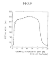
Figure 9 shows a typical example of the dependence of the spectral
width of the white pulse on a chromatic dispersion D(λ 0, 0) at the input end
of a optical medium. As seen in this example, the chromatic dispersion D(λ
0, 0) to generate white pulse having a wide spectral width is found to have a
lower limit (2 ps/nm/km) of D(λ 0, 0) and an upper limit (27 ps/nm/km).
S1E1-1e Pulse width of the pump pulse and spectral width of the white pulse
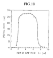
Figure 10 shows a typical example of the dependence of the spectral
width of the white pulse on the pulse width of a pump pulse. As seen in this
example, a pulse width (full width half maximum, FWHM) to generate white
pulse having a wide spectral width is found to have a lower limit (2 ps) and
an upper limit (8 ps).
Figure 11 shows a typical example of the dependence of spectral
width of the white pulse on the pulse width of a pump pulse and a chromatic
dispersion D(λ0, 0) at the input end of a optical medium. As the chromatic
dispersion D(λ0, 0) is set higher, a lower and an upper limits for FWHM of
pump pulse shift towards higher to generate white pulse having a wide
spectral width.
Specific examples are as follows. If the relation between the peak
power P0 of a pump pulse and the effective medium length L0 is:
γ P0 L0 ≧ 4.6
then, the chromatic dispersion D(λ 0, 0) at the input end and the FWHM of
the pump pulse Δt of the pump pulse should satisfy the following
expression:
0.05 Δt2 ≦ D(λ0, 0) ≦ 3.0 Δt2.
Also, when
γ P0 L0 ≧ 3.5.
then, the chromatic dispersion D(λ0, 0) at the input end and the FWHM of
the pump pulse Δt of the pump pulse should satisfy the following
expression:
0.2 Δt2 ≦ D(λ0, 0) ≦ 1.2 Δt2
For example, when γP0 = 0.00775 m-1, L0 ≧ 600 m and Δt= 4 ps and
chromatic dispersion should satisfy a relation 2 ps/nm/km ≦ D(λ 0, 0) ≦
27 ps/nm/km.
The requirements for a waveguided nonlinear optical medium to
generate white pulses are expressed in a general expression as follows:
Ln ≧ a / Dn + b + c Dn + d Dn2
where Ln is a normalized effective medium length defined as Ln = γ P0L0;
Dn is a normalized chromatic dispersion at z = 0 defined as Dn = D(Δ0,
0)/(γ P0 Δt2); a = 0.30 x 10²⁰, b = 2.9, c = -0.17 x 10⁻²⁰ and d = 0.40 x 10-40.
For example, when the peak power is 0.5 W and the pulse width is 4 ps, the
spectral widths of the white pulse output from the optical medium are
represented by a contour graph with respect to effective medium length L0
on the horizontal axis and chromatic dispersion D(λ0, 0) on the vertical axis
as shown in Figure 27. The spacing between the contour curves corresponds
to a spectral width of 25 nm.
In this case, the requirements for the optical medium to generate
white pulses are expressed by:
L0 ≧ 473/D(λ0, 0) + 374 - 1.8D(λ0, 0) + 0.34 D(λ0, 0)2
where L0 is in meter and D(λ0, 0) is in ps/nm/km.
Many of the optical materials used for nonlinear waveguides are
susceptible to Raman effect. Figure 28 shows a contour graph for spectral
widths in a typical optical material, fused silica, with respect to effective
medium length L0 on the horizontal axis and chromatic dispersion D(λ0, 0)
on the vertical axis. The values of peak power P0 and the FWHM of a pump
pulse Δt were the same as those in Figure 27, respectively, at 0.5 W and 4
ps.
In the case shown in Figure 28, the requirements to produce white
pulses are expressed as:
L0 ≧ 426 / D(λ0, 0) + 308 - 1.7 D(λ0, 0) + 0.18 D(λ0, 0)2
where L0 is in meter and D(λ 0, 0) is in ps/nm/km. Threshold value for the
effective medium length L0 to generate white pulses has been reduced
compared with the results in Figure 27. A general expression for normalized
effective medium length Ln and normalized chromatic dispersion Dn at z = 0,
with respect to the peak power P0 and the FWHM of a pump pulse Δt, is
expressed as:
Ln ≧ a / Dn + b + c Dn + d Dn2
where a = 0.26 x 10²⁰, b = 2.3, c = -0.16 x 10⁻²⁰ and d = 0.21 x 10-40.
S1E1-2 A second dispersion characteristic of chromatic dispersion
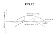
Figure 12 shows a second characteristic of chromatic dispersion in
the optical medium for use in a white pulse source of the present invention.
A feature of the second dispersion characteristic is that the center
wavelength λ0 and the peak wavelength λp(z) do not necessarily coincide
with each other, but there is some tolerance for deviation in the wavelengths,
represented by a wavelength differential Λ, according to the following
expression:
λp(L0) - Λ ≦ λ0 ≦ λp(L0) + Λ.
Figures 13A∼13C show white pulse spectra corresponding to Λ = 30, 40 and
50 nm. When the difference between the center wavelength λ0 of the pump
pulses and the peak wavelength λp(L0) is 30 or 40 nm, symmetry of the
white pulse is somewhat degraded but the degree of flatness is reasonably
acceptable. If the difference becomes 50 nm, flat spectrum cannot be
obtained.
S1E1-3 A third dispersion characteristic of chromatic dispersion
In the examples presented above, the peak wavelength λp(L0)
stayed at the same wavelength with decrease in the maximum dispersion
D(λp(L0), z); however, it is not necessary that the peak wavelength λp(L0)
remains unchanged with respect to the propagation distance z. For example,
as shown in Figure 14, the optical medium may allow some shift in the peak
wavelength λp(L0) as the maximum dispersion D(λp(L0), z) decreases.
This third dispersion characteristic is produced in practice when only the
diameters of the core and the cladding(s) in the longitudinal direction are
altered. The white pulse spectrum generated from a white pulse source
having an optical medium of such dispersion characteristics is shown in
Figure 15. It can be seen that the white pulses having high degree of flatness
over a wide range of wavelengths are obtained, as in the case of a medium
having the first or second characteristic of chromatic dispersion.
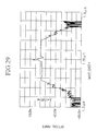
Figure 29 shows another example of white pulse spectrum
experimentally generated from an optical medium designed and
manufactured according to the third dispersion characteristic. The optical
meclium was a single-mode optical fiber which generated white pulses
having a equalized spectrum over a spectral range in excess of 200 nm.
S1E2 Embodiment 2
Generation of white pulses always passes through a stage of spectral
broadening caused by soliton compression, as discussed above. To cause this
soliton narrowing, it is not always necessary to use an optical medium
having two zero-dispersion wavelengths. That is, it is possible to connect two
types of optical media in series, as shown in Figure 16, in such a way that, in
the first stage (0 ≦ z ≦ L1), use an optical medium to satisfy requirement
(1) mentioned under E1-1, to cause soliton compression to generate spectral
broadening, and in the second stage (L1 ≦ z ≦ L), use an optical medium
to satisfy requirements (1) and (2), to cause the spectrum to become
rectangular and flat. An example of the white pulse spectrum generated by
such a configuration of optical medium is shown in Figure 17.
S1E3 Embodiment 3
In manufacturing of waveguided nonlinear optical media, the portion
that does not contribute to white pulse generation is sometimes
manufactured in addition to the portion that contributes to such a process. In
some cases, the optical medium is made so that the portion that contributes
to white pulse generation are carried out in a range of propagation distance,
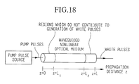
L1 ≦ z ≦ L2, as illustrated in Figure 18. In such a case also, white pulses
will be produced when the input pump pulse satisfies the requirements of
peak power and pulse width at z = L1 to enable white pulses to be generated.
S1E4 Embodiment 4
It is allowable to use an waveguided nonlinear optical medium with
optical gain in a white pulse source. Such a white pulse source is able to
generate white pulses even with low-power pump pulses that would not
produce white pulses in a optical medium with no gain, or in a short length of
optical medium.
Figure 19 shows a dependence of the spectral width of the output
white pulses on the effective medium length L0 in an optical medium with
optical gain. White circles refer to the cases of optical medium having a gain
of 0.01 dB/m and filled circles refer to the case of optical medium having a
gain of 0.05 dB/m. In this example, the parameters of the pump pulse, such
as the peak power and pulse width, and chromatic dispersion D(λ 0, 0) at the
input end of the optical medium, were kept the same as those in the optical
medium with no gain shown in Figure 7.
Compared with Figure 7, the threshold, value Lth in the effective
medium length L0 for optical medium with gain is shortened. Also, the effect
of the optical medium with gain is equivalent to that of using a high power
pump pulse according to a relation of the threshold value Lth to the peak
power of pump pulse shown in Figure 8. In other words, an amplifying
optical medium is able to generate white pulses even if the power of the
pump pulse is low or the optical medium is short.
Figure 20 is a schematic configuration of a white pulse source in
Embodiment 4 comprised by pump pulse source and an amplifying optical
medium represented by a semi-conductor amplifier and the like.
S1E5 Embodiment 5
Figure 21 is a schematic configuration of a white pulse source in
Embodiment 5. The white pulse source is comprised by: a pump pulse source;
a rare-earth-doped waveguided nonlinear optical medium; a pump source for
generating pump light to cause a population inversion in the rare-earth-doped
optical medium; and a wavelength-division optical multiplexer for
multiplexing pump light and pump pulse to be input into the rare-earth-doped
optical medium.
S1E6 Embodiment 6
Figure 22 is a schematic configuration of a white pulse source in
Embodiment 6. The white pulse source is comprised by: a pump pulse source;
a rare-earth-doped waveguided nonlinear optical medium; a pump source for
generating pump light to cause a population inversion in the rare-earth-doped
optical medium; and a wavelength-division optical multiplexer for
inputting pump light into an output end of the rare-earth-doped optical
medium; and an optical isolator to prevent the pump light which has
propagated backward the rare-earth-doped optical medium to be input into
the pump pulse source or to prevent the optical medium to oscillate like a
laser.
It is permissible to combine Embodiment 5 (forward pumping
configuration) with Embodiment 6 (backward pumping configuration). It is
also permissible to replace the rare-earth-doped optical medium with an
optical medium to produce Raman amplification, and input the pump light
into such a Raman gain optical medium.
Also, in the configurations used in Embodiments 4∼6, amplification
action can be stabilized by providing an optical isolating means to prevent
reflection of light back into the pump pulse source or the optical medium
which causes laser oscillation in the optical medium.
S1E7 Other Configurations for white pulse source
In each of the foregoing embodiments, it is possible to stabilize the
polarization of the output white pulses by providing the waveguided
nonlinear optical medium with polarization-maintaining property.
Also, in each of the foregoing embodiments, it is permissible to
provide an optical amplifier to amplify pump pulses before the input end of
the optical medium 2. This will enable to generate white pulses even by
using a pump pulse source with low power output.
The peak observed in the white pulse spectrum at the center
wavelength λ0 of the pump pulse corresponds to the pedestal of the pump
pulse which did not convert to white pulses.
In each of the foregoing embodiments, it is permissible to provide a
wavelength filter to eliminate or suppress the peak at the pump pulse
wavelength at the output end of the optical medium. This enables to
eliminate or suppress the peak whose optical power density is higher than
that of the white pulse.
Summarizing the fundamentals of the foregoing embodiments, the
present white pulse source is characterized by: 1) having an optical medium
in which the chromatic dispersion of pump pulses at the center wavelength
λ0 diminishes from a positive value to a vicinity of zero ps/nm/km in the
direction of propagation of the pump pulse; and 2) the chromatic dispersion
characteristic has a maximum value when chromatic dispersion at
wavelength λ0 is in the vicinity of zero ps/nm/km, and has two zero-dispersion
wavelengths when the maximum value is positive. This structure
prompts the spectrum of the input pump pulses to be broadened through
soliton compression and to become rectangular and flat through a process in
which a soliton pulse changes into a dispersive wave.
By utilizing an optical medium with optical gain for the waveguided
nonlinear optical medium, white pulses can be produced under less
restrictive conditions of lower power of pump pulse or shorter length of
optical medium.
Section 2: Stable-output White Pulse Sources
First, important features of the white pulse sources described in this
section will be explained.
The white pulse sources in this sections produce white pulses with
low noise by controlling the pump pulse power to reduce the noise coefficient
in the course of the white pulse generation, according to a relation of noise
coefficient to the pump pulse power.
The relation between the noise coefficient in white pulse generation
and the pump pulse power into the optical medium will be explained. The
noise coefficient is defined as a ratio of power fluctuation components
included in the white pulses (wavelength components) generated from the
optical medium to power fluctuation components included in the pump pulse.
Figure 32 is a schematic configuration for determining the noise
coefficient in white pulse generation. The pump pulse source 1 generates
pump pulses at a repetition frequency f0. This pump pulse is superimposed
with a power fluctuation component (frequency Δf, modulation index Min) in
an optical power modulator 4, and is input into the optical medium 2 at a
given optical power through an optical attenuator 5. When the white pulse
output from the optical medium 2 is filtered through a wavelength filter 3,
the filtered white pulse contains a fluctuation component (modulation index
Mout). A noise coefficient for each wavelength component in a white pulse is
obtained as a ratio, Mout/Min, of the output modulation index Mout to the input
modulation index Min.
In Figure 32, it is shown that the modulation index Min is defined as
a ratio b/a, where b is the fluctuation component at frequencies f0± Δf and a
is the carrier component at repetition frequency f0, and Mout is defined as a
ratio d/c, where d is the fluctuation component at frequencies f0± Δf and c is
the carrier component at repetition frequency f0.
Figure 33 is an example of the measurement results of noise
coefficient in the white pulses to peak power of pump pulse obtained by the
arrangement in Figure 32. The values shown in Figure 33 are actual
measurements of the noise coefficients obtained by filtering the white pulses
at different wavelengths. The center wavelength of the pump pulse is 1535
nm.
The relation of the noise coefficient to the pump pulse power is
dependent on the pulse width of the pump pulse and the chromatic
dispersion characteristics in the optical medium, but commonly, the plots of
the noise coefficient to the pump pulse power show the following features.
As indicated in Figure 33, the noise coefficient shows local minima
with respect to pump pulse power, and the pump pulse powers where the
noise coefficient has local minima shift upwards as the wavelength of the
filtered white pulse shifts further from the pump wavelength. For example,
at a wavelength 1505.03 nm (indicated by circles), the noise coefficient has
local minima at around 2.25 and 2.45 W, but for a wavelength 1476.92 nm
(squares), it has the corresponding local minima at around 2.35 and 2.51 W.
It was also observed that the higher the pump pulse power, the smaller the
noise coefficient as a whole for each wavelength component.
When the noise coefficient is higher than 0 dB, power fluctuations in
the pump pulse are amplified and transferred to the wavelength components
in the white pulse, therefore, the waveform of the white pulse becomes
distorted and the signal/noise ratio is degraded. If the noise coefficient is less
than 0 dB, power fluctuation in the pump pulse are suppressed and barely
transferred to the wavelength components in the white pulses, therefore, the
waveform is not distorted and the signal/noise ratio is rather improved.
Based on the relation of noise coefficient during the white pulse
generation to pump pulse power described above, it is possible to reduce the
noise component in the white pulses produced by controlling the pump pulse
power, thereby producing low-noise white pulses of a stable output power.
In the following, the white pulse sources developed in this section
will be described in more detail.
Figure 30 is a schematic configuration of a stable-output white pulse
source which inputs pump pulses generated in a pump pulse generation
section 51 into the optical medium 2, and a stabilization section 50 is further
provided to stabilize the optical power of white pulses output from the optical
medium 2.
The stabilization section 50 is provided with a function to control the
optical power of pump pulse to be input into the optical medium 2 to reduce
the noise component in the output white pulses according to the relation of
the noise coefficient of the white pulses generated in the optical medium 2 to
optical power of the pump pulses. Also, an optical branching section 6 is
provided before the input end, or after the output end or on both ends of the
optical medium 2 for the purpose of monitoring the optical power by the
stabilization section 50 to obtain noise coefficients. The stabilization section
50 stabilizes the output power of the white pulses by controlling the pump
pulse generation section 51 according to the noise coefficient thus obtained,
thereby reducing the noise in the white pulses.
In the following, preferred embodiments of the stable-output white
pulse source will be discussed in detail.
S2E1 Embodiment 1 in Section 2
Figure 31 shows a stable-output white pulse source of Embodiment 1.
In this embodiment, the pump pulse generation section 51 shown in
Figure 30 is comprised by: a pump pulse source 1 which is capable of
adjusting the output power; and the stabilization section 50 shown in Figure
30 is comprised by an optical power measuring section 7 to monitor the
optical power of pump pulses through a branching section 6 before the input
end of the optical medium 2, and an optical power control section 8 to control
the output power from the pump pulse source 1 so as to adjust the optical
power of the pump pulses input into the optical medium 2 to be at a target
value. The relation of the noise coefficient to the pump pulse power is pre-determined,
and the target value is selected to reduce the noise in the white
pulses according to the pre-determined relation.
For example, when this relation is as shown in Figure 33, the pump
pulse power is adjusted to be in the vicinity of 2.25 or 2.45 W to reduce the
noise coefficient at wavelength 1505.03 nm to its lowest value. Similarly, for
1490.77 nm wavelength, the pump pulse power is adjusted to be in the
vicinity of 2.31 or 2.49 W; and for 1476.92 nm wavelength, the power is
adjusted to be 2.35 or 2.51 W. To produce white pulses with overall low noise
level, the pump pulse power is adjusted to be about 2.5 W. Optical power
control section 8 adjusts the pump pulse power to be a target value by
comparing the target value with the power level monitored by the optical
power measuring section 7 and feeding-back any difference to the pump
pulse generation section 51.
S2E2 Embodiment 2
In Embodiment 1, the pump pulse generation section 51 is comprised
by a pump pulse source whose output power is adjustable, but in
Embodiment 2, the pump pulse generation section 51 is comprised by a
pump pulse source and an in-line optical power adjusting section which
controls the optical power of pump pulses to be input into the optical medium
2.
Figure 34A, 34B show schematic configurations of a second
embodiment of the stable-output white pulse source. Figure 34A shows a
feed-back scheme and Figure 34B shows a feed-forward scheme. The
stabilization section 50 is comprised by an optical power measuring section 7
and an optical power control section 8.
Pump pulse generated in the pump pulse source 1 is input through
the optical power adjusting section 9 into the optical medium 2 which
outputs white pulses. The optical power of the pump pulses is monitored by
the optical power measuring section 7 through the optical branching section
6 disposed on the fore- or aft-stage of the optical power adjusting section 9.
The optical power control section 8 controls the power adjusting section 9 to
minimize the difference between a optical power of pump pulses monitored
by the power measuring section 7 and a target value so that the pump pulse
power input into the optical medium 2 is at the target value. Also, the optical
power adjusting section 9 may use either or both of optical amplifying device
or optical attenuating device.
S2E3 to S2E8
This section describes Embodiments 3 to 8 in Section 2. In
Embodiments 1 and 2, the relation of noise coefficient to pump pulse power
was pre-determined and a target value of pump pulse power was selected to
reduce the noise coefficient. In Embodiments S2E3∼S2E8, fluctuation
components are deliberately superimposed on the pump pulses and the noise
coefficient is measured in real-time, so that the pump pulse power can be
feedback-controlled according to the measured noise coefficient.
Figure 35 shows Embodiment 3 in Section 2.
In this embodiment, the pump pulse generation section 51 shown in
Figure 30 is comprised by: a pump pulse source 1 which is capable of
adjusting the output power and an optical power modulator 4; and the
stabilization section 50 shown in Figure 30 is comprised by an optical power
control section 11 and a modulation component measuring section 10.
Pump pulses generated in the pump pulse source 1 are input through
the optical power modulator 4 to superimpose a power fluctuation of a given
level of modulation index Min into the optical medium 2 which generates
white pulses. The modulation index Mout contained in the output white
pulses is measured by the modulation component measuring section 10
through an optical branching section 6 after the output end of the optical
medium 2. Optical power control section 11 figures out a noise coefficient as a
ratio Mout/Min, and controls the pump pulse source 1 to minimize the noise
coefficient related to pump pulse power.
Figure 36 shows Embodiment 4 in Section 2.
In this embodiment, the pump pulse generation section 51 shown in
Figure 30 is comprised by: a pump pulse source 1, an in-line optical power
adjusting section 9, and an optical power modulator 4; and the stabilization
section 50 shown in Figure 30 is comprised by an optical power control
section 11 and a modulation component measuring section 10.
Pump pulses output from the pump pulse source 1 are input through
the optical power modulator 4 to superimpose a power fluctuation of a given
level of modulation index Min and are then input through an optical power
adjusting section 9, into the optical medium 2 which generates white pulses.
The modulation index Mout contained in the output white pulses is measured
by monitoring the optical power of the white pulse in the modulation
component measuring section 10 through an optical branching section 6 after
the output end of the optical medium 2. Optical power control section 11
figures out a noise coefficient as a ratio Mout/Min, and controls the optical
power adjusting section 9 to minimize the noise coefficient related to pump
pulse power. Also, the optical power control section 9 may use either or both
of optical amplifier device or optical attenuator device.
In Figure 36, the optical power adjusting section 9 is located before
the optical power modulation device 4, but it is permissible to locate the
optical power modulation device 4 after the optical power adjusting section.
In Embodiments 5 and 6, the modulation index Min to be
superimposed on the pump pulse at the input side of the optical medium 2 is
made constant. In this case, the pump pulse power is adjusted according to
the modulation index Mout because the noise coefficient corresponds to the
modulation index Mout contained in the white pulses.
Figure 37 shows Embodiment 5 in Section 2.
In this embodiment, the pump pulse generation section 51 shown in
Figure 30 is comprised by: a pump pulse source 1 which is capable of
adjusting the output power and an optical power modulator 4; and the
stabilization section 50 shown in Figure 30 is comprised by an optical power
control section 11 and a modulation component measuring section 10.
Pump pulses generated in the pump pulse source 1 are input through
the optical power modulator 4 to superimpose a power fluctuation of a given
level of modulation index Min, and into the optical medium 2 which generates
white pulses. The modulation index Mout contained in the output white
pulses is measured by monitoring the optical power of the white pulse in the
modulation component measuring section 10 through an optical branching
section 6 after the output end of the optical medium 2. Optical power control
section 11 controls the pump pulse source 1 to minimize the modulation
index Mout of the white pulses being measured by the modulation component
measuring section 10, and adjusts the pump pulse power to be input into the
optical medium 2.
Figure 38 shows Embodiment 6 in Section 2.
In this embodiment, the pump pulse generation section 51 shown in
Figure 30 is comprised by: a pump pulse source 1, an in-line optical power
adjusting section 9, and an optical power modulator 4; and the stabilization
section 50 shown in Figure 30 is comprised by an optical power control
section 11 and a modulation component measuring section 10.
Pump pulses generated in the pump pulse source 1 are input through
the optical power modulator 4 to superimpose a power fluctuation of a given
level of modulation index Min and are then input through the optical power
adjusting section 9, into the optical medium 2 which generates white pulses.
The modulation index Mout contained in the output white pulses is measured
by moninoring the optical power of the white pulse in the modulation
component measuring section 10 through an optical branching section 6 after
the output end of the optical medium 2. Optical power control section 11
controls the optical power adjusting section 9 to minimize the modulation
index Mout of the white pulses being measured by the modulation component
measuring section 10, and adjusts the pump pulse power to be input into the
optical medium 2. Also, the optical power control section 9 may use either or
both of optical amplifying device or optical attenuating device.
In Figure 38, the optical power adjusting section 9 is located before
the optical power modulation device 4, but it is permissible to locate the
optical power modulation device 4 after the optical power adjusting section.
Embodiments 3∼6 utilized modulation index Mout of the white pulses,
i.e., overall values of the modulation index for all wavelengths are being
measured. Thus, the pump pulse power is controlled so as to achieve overall
low noise in the white pulses. In contrast, Embodiments 7 and 8 presented in
the following are directed to controlling the pump pulse power to minimize
the noise in a particular wavelength component in the white pulse. In these
embodiments, the configurations correspond to those used in Embodiments 5
and 6, but this technique can be applied equally well to the configurations in
Embodiments 3 and 4.
Figure 39 shows Embodiment 7 in Section 2.
In this embodiment, the pump pulse generation section 51 shown in
Figure 30 is comprised by: a pump pulse source 1 which is capable of
adjusting the output power and an optical power modulator 4; and the
stabilization section 50 shown in Figure 30 is comprised by an optical power
control section 11, a modulation component measuring section 10 and a
wavelength filter 3.
The feature of this embodiment is that white pulses split in the
optical branching section 6 (refer to Figure 37) is monitored by the
modulation component measuring section 10 through a wavelength filter 3
having a specific wavelength band. The modulation component measuring
section 10 measures a modulation component for the wavelength band
transmitted through the optical filter 3, therefore, the noise component in
the white pulses is minimized particularly in the wavelength band
designated by the wavelength filter 3.
Figure 40 shows Embodiment 8 in Section 2.
In this embodiment, the pump pulse generation section 51 shown in
Figure 30 is comprised by: a pump pulse source 1, an in-line optical power
adjusting section 9, and an optical power modulator 4; and the stabilization
section 50 shown in Figure 30 is comprised by an optical power control
section 11, a modulation component measuring section 10 and a wavelength
filter 3.
The feature of this embodiment is that white pulses split in the
optical branching section 6 (refer to Figure 38) is monitored by the
modulation component measuring section 10 through a wavelength filter 3
having a specific wavelength band. The modulation component measuring
section 10 measures a modulation component for the wavelength band
transmitted through the optical filter 3, therefore, the noise component in
the white pulses is minimized particularly in the wavelength band
designated by the wavelength filter 3.
Figure 40 shows the optical power adjusting section after the optical
power modulator 4, but it can be placed before the modulator 4.
S2E9 and S2E10
The section presents Embodiments 9 and 10 in Section 2.
Embodiments 9, 10 directly measure the noise components in white
pulses to control the pump pulse power and to reduce the noise components.
The noise components originate from the pump pulse source, and are
transferred from the pump pulses to the white pulses in the course of the
white pulse generation.
Figure 41 shows Embodiment 9 in Section 2.
In this embodiment, the pump pulse generation section 51 shown in
Figure 30 is comprised by: a pump pulse source 1 which is capable of
adjusting the output power; and the stabilization section 50 shown in Figure
30 is comprised by an optical power control section 13 and a noise component
measuring section 12.
Pump pulses generated in the pump pulse source 1 are input into the
optical medium 2 which generates white pulses. The noise components
contained in the output white pulses is measured by monitoring the optical
power of the white pulse in the noise component measuring section 12
through an optical branching section 6 after the output end of the optical
medium 2. Optical power control section 13 controls the pump pulse source 1
to minimize the noise component of the white pulses being measured by the
noise component measuring section 12, and adjusts the pump pulse power to
be input into the optical medium 2.
Figure 42 shows Embodiment 10 in Section 2.
In this embodiment, the pump pulse generation section 51 shown in
Figure 30 is comprised by: a pump pulse source 1, and an in-line optical
power adjusting section 9; and the stabilization section 50 shown in Figure
30 is comprised by an optical power control section 13 and a noise component
measuring section 12.
Pump pulses generated in the pump pulse source 1 are input,
through the optical power adjusting section 9, into the optical medium 2
which generates white pulses. The noise components contained in the output
white pulses is measured by monitoring the optical power of the white pulse
in the noise component measuring section 12 through an optical branching
section 6 after the output end of the optical medium 2. Optical power control
section 13 controls the optical power adjusting section 9 to minimize the
noise component of the white pulses being measured by the noise component
measuring section 10, and adjusts the pump pulse power to be input into the
optical medium 2. Also, either or both optical amplifier and optical
attenuator may be used in the optical power control section 9.
It is permissible to apply the configurations used for Embodiments 7
and 8 to Embodiments 9, 10 to control the noise in the white pulses, by
disposing a wavelength filter 3 between the optical branching section 6 after
the output end of the optical medium 2 and the noise component measuring
section 12.
S2E11 Embodiment 11
In each of the foregoing embodiments 2, 4, 6, 8 and 10 in Section 2, it
is also permissible to input with external pump pulses for generating white
pulses.
Figure 45 shows Embodiment 11 in Section 2 which accepts external
pump pulses through a pump pulse input section 55 into the optical medium
2, and a stabilization section 50 is provided to stabilize the optical power of
white pulses output from the optical medium 2.
As is mentioned in those corresponding embodiments 2, 4, 6, 8 and
10, the stabilization section 50 is provided with a function to control the
pump pulse input section 55 to adjust optical power of pump pulse to be
input into the optical medium 2 to reduce the noise component in the output
white pulses according to the relation of the noise coefficient of the white
pulses generated in the optical medium 2 to optical power of the pump
pulses.
Section 2a Noise Components Measuring Method
Figure 43 shows an example of measuring the noise components
output from a white pulse source utilizing a harmonically mode-locked pulse
laser as a pump pulse source.
This method is valid when using a harmonically mode-locked pulse
laser generating repetition frequency components Nf (where f is
fundamental mode frequency and Nis an integer larger than 2) as the pump
pulse source 1. Frequency components other than the repetition frequency
components or their harmonic components nNf(n is an integer) contribute as
intensity noise to the output pump pulses, therefore, these frequency
components Mf(M is an integer other than nN) are monitored and the pump
pulse power is adjusted to minimize components at frequencies Mf in the
white pulses.
Figure 44 shows an example of measuring the low-frequency noise
components output from a white pulse source.
This method is valid when using a mode-locked pulse laser as the
pump pulse source 1. Spectral components at a relaxation oscillation
frequency from such laser source contribute as low-frequency intensity noise,
which can be monitored and used as a feedback flag to reduce its value.
Section 2b Other Embodiments
In each of the foregoing embodiments, by using a white pulse source
which generates a equalized spectrum over a wide bandwidth, the
wavelength-dependency of the spectrum of the output white pulses can be
reduced considerably. Such a white pulse source, as explained in Section 1,
can be realized by using a waveguided nonlinear optical medium 2 that
exhibits a chromatic dispersion characteristics shown in Figures 1, 13 and
15.
In other words, the optical medium 2 should satisfy the requirements
that: (1) the chromatic dispersion at the wavelength of the pump pulse
decreases from positive value to less than zero in the propagation direction of
the pump pulse; and (2) over the entire or partial range of propagation
distance in the optical medium, the chromatic dispersion characteristic
shows two zero-dispersion wavelengths, both of which approach the
wavelength of the pump pulse with the propagation distance from the input
end.
It will be recalled that Figure 1 is an example of the chromatic
dispersion characteristic where the center wavelength λ0 of pump pulses
coincides with the peak wavelength of the chromatic dispersion, and Figure
12 is an example of the chromatic dispersion characteristic where the center
wavelength λ0 of pump pulses does not necessarily coincide with the peak
wavelength of the chromatic dispersion, and Figure 14 is an example in
which the peak wavelength of the chromatic dispersion varies along the
propagation direction.
By using a waveguided nonlinear optical medium designed according
to the present embodiment, a stable-output white pulse source will be able to
generate white pulses having a equalized-output optical power over a wide
bandwidth.
Also, in each of the foregoing embodiments, it is possible to stabilize
the polarization of the output white pulses by providing the waveguided
nonlinear optical medium with polarization-maintaining property for
generating stable-output white pulses.
Also, in each of the foregoing embodiments, it is permissible to
provide an optical amplifier to amplify pump pulses before the input end of
the optical medium 2. This will enable to generate white pulses even by
using a pump pulse source with low power output.
In each of the foregoing embodiments, it is also permissible to
provide a wavelength filter to eliminate or suppress the spectral peak at the
pump pulse wavelength which corresponds to the pedestal of the pump pulse
as described in Section 1. This enables to eliminate or suppress the spectral
peak whose optical power density is higher than that of the white pulse.
Summarizing the above, the present stable-output white pulse
source enables to minimize noise in the output white pulses by controlling
the optical power of pump pulses input into the optical medium, thereby
generating low-noise white pulses that are unaffected by the power
fluctuations occurring in the pump pulses.
Section 3 Low-Noise Optical Pulses from White Pulse Sources
First, the features of the low-noise white pulse source in Section 3
will be explained.
A low-noise white pulse source filters out a specific wavelength from
the output white pulses, and minimizes the noise coefficient at the specific
wavelength by controlling the pump pulse power according to a relation of
the noise coefficient to the pump pulse power in the white pulse generation.
As explained in regard to Figure 33 in Section 2, the noise coefficient
in the white pulse generation depends sensitively on the optical power of
pump pulses, and there is a specific values of pump pulse power at which the
noise coefficient is reduced to less than 0 dB. The pump pulse powers where
the noise coefficient has local minima shift upwards as the wavelength of the
filtered white pulse shifts further from the pump wavelength. For example,
at a wavelength 1505.03 nm (indicated by circles), the noise coefficient has
local minima at around 2.25 and 2.45 W, but for a wavelength 1476.92 nm
(squares), it has the corresponding local minima at around 2.35 and 2.51 W.
The signal to noise ratio of optical pulses obtained by filtering the
white pulses at a specific wavelength is given by a product of the noise
coefficient and the signal to noise ratio of the pump pulse, therefore, the level
of the noise coefficient affects the purity of the optical pulses obtained by
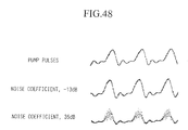
filtering the white pulses at a specific wavelength, as illustrated in Figure
48. When the level of the noise coefficient is higher than 0 dB (35 dB in
Figure 48), the power fluctuation in the pump pulse is amplified and
transferred onto the white pulses, so that the waveform of the optical pulse
obtained by filtering from the white pulses is also seriously degraded. On the
other hand, when the level of the noise coefficient is less than 0 dB (-13 dB in
Figure 48), the power fluctuation occurring in the pump pulse is suppressed
and is barely transferred onto the white pulses so that the waveform is not
degraded and may even be improved. It follows that, by controlling the pump
pulse power so that the noise coefficient at a specific wavelength will be less
than 0 dB, according to a relation of the noise coefficient to pump pulse
power, it is possible to generate optical pulses having a lower noise level than
that in the pump pulses.
The low-noise pulse sources will be explained in detail in the
following.
Figure 46 is a schematic configuration of a low-noise-output white
pulse source in which pump pulses generated in a pump pulse generation
section 61 are input into the optical medium 2, and white pulses generated in
the optical medium 2 are filtered through a wavelength filter 3 to output an
optical pulse of a specific wavelength. A noise reduction section 60 is further
provided to minimize the noise components in the output pulses of the
wavelength filter 3.
The noise reduction section 60 is provided with a function to control
the optical power of pump pulse to be input into the optical medium 2,
according to a relation of noise coefficient to pump pulse power, so as to
minimize the noise coefficient to less than 0 dB. An optical branching section
6 is provided either before the input end of the optical medium 2 or after the
wavelength filter 3 or at both ends, for the purpose of monitoring the optical
power by the noise reduction section 60 to obtain a noise coefficient. The
noise reduction section 60 controls the pump pulse generation section 61
accorcling to the noise coefficient thus obtained, thereby reducing the noise in
the output pulses from the wavelength filter 3.
Some examples of the noise reduction configurations will be
explained in detail in the following.
S3E1 Embodiment 1 in Section 3
Figure 47 is a schematic configuration of the low-noise pulse source
of Embodiment 1 in Section 3.
In this embodiment, the pump pulse generation section 61 shown in
Figure 46 is comprised by: a pump pulse source 1 which is capable of
adjusting the output power; and the noise reduction section 60 shown in
Figure 46 is comprised by an optical power measuring section 7 to monitor
the optical power of pump pulses through a branching section 6 before the
input end of the optical medium 2, and an optical power control section 8 to
control the output power from the pump pulse source 1 so as to adjust the
optical power of the pump pulses input into the optical medium 2 to be at a
target value. The relation of the noise coefficient to the pump pulse power is
pre-determined, and the target value is selected to reduce the noise
coefficient for the specific wavelength of the wavelength filter 3, at less than
0 dB according to the pre-determined relation.
For example, when this relation is as shown in Figure 33, the pump
pulse power is adjusted to be in the vicinity of 2.25 or 2.45 W to minimize the
noise coefficient to less than 0 dB at a wavelength of 1505.03 nm. Similarly,
for 1490.77 nm wavelength, the pump pulse power is adjusted to be in the
vicinity of 2.31 or 2.49 W; and at a wavelength of 1476.92 nm, the power is
adjusted to be 2.35 or 2.51 W. Optical power control section 8 adjusts the
pump pulse power to be a selected target value by comparing the target
value with the power level monitored by the optical power measuring section
7 and feeding-back any difference to the pump pulse source 1.
S3E1 Embodiment 2 in Section 3
In Embodiment 1, pump pulse generation section 61 was comprised
by a pump pulse source whose output power is adjustable, but in
Embodiment 2, pump pulse generation section 61 is comprised by a pump
pulse source and an in-line optical power adjusting section which controls
the pump pulse power to be input into the optical medium 2.
Figure 49 is a schematic configuration of the low-noise optical pulse
source of Embodiment 2 in Section 3. Figure 49A shows a feed-back scheme
and Figure 49B shows a feed-forward scheme. The stabilization section 60 is
comprised by an optical power measuring section 7 and an optical power
control section 8.
Pump pulses generated in the pump pulse source 1 are input,
through the optical power adjusting section 9, into the optical medium 2, and
the output white pulses are filtered by a wavelength filter 3 to output optical
pulses of a specific wavelength. The optical power of pump pulses is
monitored by the optical power measuring section 7 through the optical
branching section 6 disposed on the fore- or aft-stage of the optical power
adjusting section 9. The optical power control section 8 controls the optical
power adjusting section 9 to minimize the difference between the optical
power of pump pulses monitored by the power measuring section 7 and a
target value to adjust the pump pulse power into the optical medium 2 at the
target value. The optical power control section 9 may be represented by
either or both of optical amplifier and optical attenuator.
S3E3∼S3E6 Embodiments 3 to 6 in Section 3
Embodiments 1 and 2 were based on an approach of pre-determining
a relation of the noise coefficient to pump pulse power, and the pump pulse
power was controlled so that the noise coefficient at the wavelength specified
by a wavelength filter 3 is minimized to less than 0 dB. In contrast, in the
following Embodiments 3∼6, fluctuation components are deliberately
superimposed on the pump pulses and the noise coefficient depending on
pump pulse power is measured in real-time, so that the pump pulse power
can be feedback-controlled according to the measured noise coefficient.
Figure 50 shows Embodiment 3 in Section 3.
In this embodiment, the pump pulse generation section 61 shown in
Figure 46 is comprised by: a pump pulse source 1 which is capable of
adjusting the output power and an optical power modulator 4; and the noise
reduction section 60 shown in Figure 46 is comprised by an optical power
control section 11 and a modulation component measuring section 10.
Pump pulses generated in the pump pulse source 1 are input through
the optical power modulator 4 to superimpose a power fluctuation of a given
level of modulation index Min into the optical medium 2 which generates
white pulses which are filtered through a wavelength filter 3 to produce
optical pulses of a specific wavelength. The modulation index Mout contained
in the output pulses from the wavelength filter 3 is measured by the
modulation component measuring section 10 through an optical branching
section 6 disposed after the output end of the wavelength filter 3. Optical
power control section 11 figures out a noise coefficient as a ratio Mout/Min, and
controls the pump pulse source 1 so as to minimize the noise coefficient
related to pump pulse power.
Figure 51 shows Embodiment 4 in Section 3.
In this embodiment, the pump pulse generation section 61 shown in
Figure 46 is comprised by: a pump pulse source 1, an in-line optical power
adjusting section 9, and an optical power modulator 4; and the noise
reduction section 60 shown in Figure 46 is comprised by an optical power
control section 11 and a modulation component measuring section 10.
Pump pulses generated in the pump pulse source 1 are input through
the optical power modulator 4 to superimpose a power fluctuation of a given
level of modulation index Min and are then input through an optical power
adjusting section 9, into the optical medium 2 which generates white pulses
which are filtered through a wavelength filter 3 to produce optical pulses of a
specific wavelength. The modulation index Mout contained in the output
pulses from the wavelength filter 3 is measured by the modulation
component measuring section 10 through an optical branching section 6
disposed after the output end of the wavelength filter 3. Optical power
control section 11 figures out a noise coefficient as a ratio Mout/Min, and
controls the optical power adjusting section 9 so as to minimize the noise
coefficient related to pump pulse power. Also, the optical power control
section 9 may use either or both of optical amplifying device or optical
attenuating device.
In Figure 51, the optical power adjusting section is provided after the
optical power modulation device 4, but it may be provided before the device
4.
Embodiments 5 and 6 controlled the pump pulse power according to
Mout contained in the white pulses, because for a constant value of the
modulation index Min superimposed on the pump pulse, the noise coefficient
is equivalent to modulation index Mout.
Figure 52 shows Embodiment 5 in Section 3.
In this embodiment, the pump pulse generation section 61 shown in
Figure 46 is comprised by: a pump pulse source 1 which is capable of
adjusting the output power and an optical power modulator 4; and the noise
reduction section 60 shown in Figure 46 is comprised by an optical power
control section 11 and a modulation component measuring section 10.
Pump pulses generated in the pump pulse source 1 are input through
the optical power modulator 4 to superimpose a power fluctuation of a given
level of modulation index Min and are then input into the optical medium 2
which generates white pulses which are filtered through a wavelength filter
3 to produce optical pulses of a specific wavelength. The modulation index
Mout contained in the output pulses from the wavelength filter 3 is measured
by the modulation component measuring section 10 through an optical
branching section 6 disposed after the output end of the wavelength filter 3.
Optical power control section 11 controls the pump pulse source 1 so as to
minimize the modulation index Mout equivalent to noise coefficient related to
pump pulse power.
Figure 53 shows Embodiment 6 in Section 3.
In this embodiment, the pump pulse generation section 61 shown in
Figure 46 is comprised by: a pump pulse source 1, an in-line optical power
adjusting section 9, and an optical power modulator 4; and the noise
reduction section 60 shown in Figure 46 is comprised by an optical power
control section 11 and a modulation component measuring section 10.
Pump pulses generated in the pump pulse source 1 are input through
the optical power modulator 4 to superimpose a power fluctuation of a given
level of modulation index Min and are then input through an optical power
adjusting section 9, into the optical medium 2 which generates white pulses
which are filtered through a wavelength filter 3 to produce optical pulses of a
specific wavelength. The modulation index Mout contained in the output
pulses from the wavelength filter 3 is measured by the modulation
component measuring section 10 through an optical branching section 6
disposed after the output end of the wavelength filter 3. Optical power
control section 11 controls the optical power adjusting section 9 so as to
minimize the modulation index Mout equivalent to noise coefficient related to
pump pulse power. Also, the optical power control section 9 may use either or
both of optical amplifying device or optical attenuating device.
In Figure 53, the optical power adjusting section is provided after the
optical power modulation device 4, but it may be provided before the device
4.
S3E7 and S3E8 Embodiments 7 and 8
The section presents Embodiments 7 and 8 in Section 3.
Embodiments 7, 8 are based on the direct measurement and feedback
control of noise components in an optical pulse obtained by filtering white
pulses with a wavelength filter 3 to reduce the noise components. The noise
components originate from the pump pulse source, and are transferred from
the pump pulses to the white pulses in the course of the white pulse
generation.
Figure 54 shows Embodiment 7 in Section 3.
In this embodiment, the pump pulse generation section 61 shown in
Figure 46 is comprised by: a pump pulse source 1 which is capable of
adjusting the output power; and the noise reduction section 60 shown in
Figure 46 is comprised by an optical power control section 13 and a noise
component measuring section 12.
Pump pulses generated in the pump pulse source 1 are input into the
optical medium 2 to generate white pulses which are filtered through a
wavelength filter 3 to produce optical pulses of a specific wavelength. The
noise component contained in the output pulses from the wavelength filter 3
is measured by the noise component measuring section 12 through an optical
branching section 6 disposed after the output end of the wavelength filter 3.
The optical power control section 13 controls the pump pulse source 1 so as to
minimize the noise components monitored by the noise component
measuring section 12.
Figure 55 shows Embodiment 8 in Section 3.
In this embodiment, the pump pulse generation section 61 shown in
Figure 46 is comprised by: a pump pulse source 1 and an in-line optical
power adjusting section 9; and the noise reduction section 60 shown in
Figure 46 is comprised by an optical power control section 13 and a noise
component measuring section 12.
Pump pulses generated in the pump pulse source 1 are input through
the optical power adjusting section 9, and are input into the optical medium
2 to generate optical pulses which are filtered through a wavelength filter 3
to produce optical pulses of a specific wavelength. The noise component
contained in the output pulses from the wavelength filter 3 is measured by
the noise component measuring section 12 through an optical branching
section 6 disposed after the output end of the wavelength filter 3. The optical
power control section 13 controls the optical power adjusting section 9 so as
to minimize the noise components monitored by the noise component
measuring section 12. Also, either or both optical amplifier and optical
attenuator may be used in the optical power control section 9.
S3E9 Embodiment 9
In each of the foregoing embodiments 2, 4, 6 and 8 in Section 3, it is
also permissible to input with external pump pulses for generating white
pulses.
Figure 56 shows Embodiment 9 in Section 3 which accepts external
pump pulses through a pump pulse input section 65 into the optical medium
2, and a noise reduction section 60 is provided to minimize the noise level in
the optical pulses output from the wavelength filter 3.
As is mentioned in those corresponding embodiments 2, 4, 6 and 8,
the noise reduction section 60 is provided with a function to control the pump
pulse input section 65 to adjust optical power of pump pulse to be input into
the optical medium 2 to reduce the noise level in the optical pulses output
from the wavelength filter 3 even lower than that of the pump pulses
according to the relation of the noise coefficient to pump pulse power.
S3a Noise Components Measuring Method
The method of measuring the noise components is the same as that
explained in Section 2 with reference to Figures 44 and 45, and it will not be
repeated.
Section 3b Other Embodiments
The effects of the low-noise white pulse source described in Section 3
are very much the same as those in Section 2 and will not be repeated.
It is important to emphasize, however, that the optical medium 2
should again satisfy the same requirements as expressed previously, namely
that: (1) the chromatic dispersion at the wavelength of the pump pulse
decreases from positive value to less than zero in the propagation direction of
the pump pulse; and (2) over the entire or partial range of propagation
distance in the optical medium, the chromatic dispersion characteristic
shows two zero-dispersion wavelengths, both of which approach the
wavelength of the pump pulse with the propagation distance from the input
end.
By using the present design of the waveguided nonlinear optical
medium as explained in this section, it is possible to reduce the wavelength-dependency
of the filtered optical pulse from the white pulse generated
because of its equalized spectrum over a wide bandwidth.
In each of the foregoing embodiments, the filter 3 may be a single
wavelength, a multiple wavelengths or a variable wavelength filter. When
using a multiple-wavelength filter, the modulation component or noise
component to be monitored are the maximums in each wavelength band.
As in Section 2, the waveguided nonlinear optical medium 2 in each
of the foregoing embodiments may be provided with polarization-maintaining
property to generate polarization-maintaining white pulses so
that optical waves having a stable polarization may be propagated in the
optical medium. It follows that any filtered optical pulse would also have a
stable optical polarization.
As in Section 2, in each of the foregoing embodiments, it is
permissible to provide an optical amplifier to amplify pump pulses before the
input end of the optical medium 2. This will enable to generate white pulses
even by using a pump pulse source with low power output.
Summarizing the above, the present low-noise pulse source
minimizes the noise coefficient of the filtered optical pulse from the white
pulses to less than 0 dB by controlling the optical power of pump pulses
input into the optical medium, thereby generating optical pulses which have
lower noise than that of the pump pulses.