EP0886101A2 - Lamp for motor-vehicles - Google Patents
Lamp for motor-vehicles Download PDFInfo
- Publication number
- EP0886101A2 EP0886101A2 EP98830368A EP98830368A EP0886101A2 EP 0886101 A2 EP0886101 A2 EP 0886101A2 EP 98830368 A EP98830368 A EP 98830368A EP 98830368 A EP98830368 A EP 98830368A EP 0886101 A2 EP0886101 A2 EP 0886101A2
- Authority
- EP
- European Patent Office
- Prior art keywords
- lamp
- transparent plate
- lamp according
- light source
- reflective element
- Prior art date
- Legal status (The legal status is an assumption and is not a legal conclusion. Google has not performed a legal analysis and makes no representation as to the accuracy of the status listed.)
- Granted
Links
- 230000003287 optical effect Effects 0.000 claims description 5
- 230000000694 effects Effects 0.000 claims description 4
- 230000008878 coupling Effects 0.000 claims description 3
- 238000010168 coupling process Methods 0.000 claims description 3
- 238000005859 coupling reaction Methods 0.000 claims description 3
- 239000011159 matrix material Substances 0.000 claims description 2
- 230000002093 peripheral effect Effects 0.000 claims description 2
- 239000000463 material Substances 0.000 description 4
- 238000004519 manufacturing process Methods 0.000 description 3
- XAGFODPZIPBFFR-UHFFFAOYSA-N aluminium Chemical compound [Al] XAGFODPZIPBFFR-UHFFFAOYSA-N 0.000 description 2
- 229910052782 aluminium Inorganic materials 0.000 description 2
- 239000004411 aluminium Substances 0.000 description 2
- 238000010586 diagram Methods 0.000 description 2
- 238000010276 construction Methods 0.000 description 1
- 238000005323 electroforming Methods 0.000 description 1
- 238000000034 method Methods 0.000 description 1
- 238000000465 moulding Methods 0.000 description 1
Images


Classifications
-
- F—MECHANICAL ENGINEERING; LIGHTING; HEATING; WEAPONS; BLASTING
- F21—LIGHTING
- F21S—NON-PORTABLE LIGHTING DEVICES; SYSTEMS THEREOF; VEHICLE LIGHTING DEVICES SPECIALLY ADAPTED FOR VEHICLE EXTERIORS
- F21S43/00—Signalling devices specially adapted for vehicle exteriors, e.g. brake lamps, direction indicator lights or reversing lights
- F21S43/40—Signalling devices specially adapted for vehicle exteriors, e.g. brake lamps, direction indicator lights or reversing lights characterised by the combination of reflectors and refractors
-
- F—MECHANICAL ENGINEERING; LIGHTING; HEATING; WEAPONS; BLASTING
- F21—LIGHTING
- F21S—NON-PORTABLE LIGHTING DEVICES; SYSTEMS THEREOF; VEHICLE LIGHTING DEVICES SPECIALLY ADAPTED FOR VEHICLE EXTERIORS
- F21S43/00—Signalling devices specially adapted for vehicle exteriors, e.g. brake lamps, direction indicator lights or reversing lights
- F21S43/20—Signalling devices specially adapted for vehicle exteriors, e.g. brake lamps, direction indicator lights or reversing lights characterised by refractors, transparent cover plates, light guides or filters
- F21S43/255—Filters
-
- F—MECHANICAL ENGINEERING; LIGHTING; HEATING; WEAPONS; BLASTING
- F21—LIGHTING
- F21S—NON-PORTABLE LIGHTING DEVICES; SYSTEMS THEREOF; VEHICLE LIGHTING DEVICES SPECIALLY ADAPTED FOR VEHICLE EXTERIORS
- F21S43/00—Signalling devices specially adapted for vehicle exteriors, e.g. brake lamps, direction indicator lights or reversing lights
- F21S43/30—Signalling devices specially adapted for vehicle exteriors, e.g. brake lamps, direction indicator lights or reversing lights characterised by reflectors
Definitions
- the present invention relates to the field of motor-vehicle lamps.
- the object of the present invention is that of solving all the above mentioned problems efficiently by providing a lamp which has a minimum bulk along the direction orthogonal to the transparent element of the lamp, which is simple and inexpensive to manufacture and ensures that a uniform light beam is obtained at the output, having the required characteristics, even in case the lamp is positioned at an area of the motor-vehicle which is not ideal in order to achieving a good rearward lighting, such as at a side edge of the rear part of the motor-vehicle.
- the invention provides a lamp for motor-vehicles comprising:
- These lateral areas may be also defined by a plurality of paraboloid segments located side by side along said first direction or alternatively may have a smooth surface.
- the surface of the main reflective wall is optimized in order to lighten the transparent plate uniformly and the paraboloid segments are calculated in order to provide a light beam coming out of the lamp body in the required direction.
- the light source with the auxiliary reflective element associated therewith is positioned on one side of the lamp body, either centrally with respect to this side, or at one end thereof, at one edge of the lamp body.
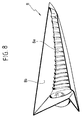
- This auxiliary reflective element has a cylindroid-like surface and forms, along with the light source associated therewith, a single unit provided with means for quick coupling to the lamp body.
- the light source is preferably constituted by a lamp whose base is arranged transversely with respect to the optical axis of the auxiliary reflective elements and is received within a notch formed in the front edge of the auxiliary reflective element. Therefore, in order to replace the lamp, it is necessary to disengage the auxiliary element from the lamp body and then remove the electric lamp from the front notch of the auxiliary reflective element, proceeding thereafter in the opposite way in order to install the new electric lamp. This solution further reduces the bulk of the lamp according to the invention.
- the main reflective wall is able to give raise to a uniform light beam, having the required characteristics, without the need of providing further prisms on the transparent plate, even if of course this possibility remains available to the designer.
- the lamp according to the invention solves all the above mentioned problems brilliantly, while keeping the bulk along the direction orthogonal to the transparent plate extremely reduced, which renders possible to position the lamp even at areas of the motor-vehicle where the available space is very reduced.
- reference numeral 1 generally designates a rear light unit for a motor-vehicle, which is to be arranged along the righthand lateral edge of the rear portion of a motor-vehicle.
- the light unit 1 comprises a plurality of lamps 2, 3, 4, 5, 6 which are aligned vertically above each other, at least one of which is made according to the present invention.
- lamp 2 In the following, reference will be made, purely by way of example, to lamp 2.
- the lamp comprises a box-like body opened at the front.
- the front aperture of the box-like body which is preferably made of plastic material, is closed by a transparent plate 7 (see figure 2).
- the wall of the hollow body of the lamp which faces the transparent plate 7 constitutes a main reflective wall 8 having a central area 8a and two lateral areas 8b.
- the dimension of the lamp along the direction orthogonal to the transparent plate 7 is greatly reduced with respect to the other dimensions of the lamp.
- the reflective wall 8 is relatively close to the transparent plate 7. This arrangement is possible since with the lamp 2 there is associated a light source 9 which is constituted by an electric lamp which is arranged at one side of the lamp body and surrounded by an auxiliary reflective element 10.
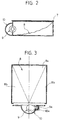
- Figures 3, 5 show two possible alternatives in which the lamp 9 is arranged at one side of the lamp body, at the center of this side (figure 3) or at one end thereof (figure 4) at one edge of the lamp body (as shown also in figure 1).
- figure 4 is preferred to that of figure 3 since it provides a greater value of the ratio between the surface of the central area 8a and the total surface of the reflective wall 8.
- the central area 8a and the lateral areas 8b of the reflective wall 8 can be made as to form a continuous surface, as shown in figure 5.
- the electric lamp 9 has a base 9a which is arranged transversely with respect to the optical axis of the auxiliary reflective element 10 and is received within a notch 10a formed in the front edge of the reflective element 10.
- the reflective element 10 and electric lamp 9 form a single unit provided with means of any known type (not shown) for quick coupling to the body of lamp 2.
- the arrangement shown in figure 7 minimizes the bulk of the device in the case of two or more adjacent lamps, where the auxiliary reflective element 10 of each lamp is fitted under the reflective wall 8 of the adjacent lamp.
- the transparent plate 7 can be arranged side by side with no remaining non-illuminated gaps between adjacent lamps.
- the central area 8a has a number of paraboloid segments arranged side by side along the direction of the optical axis of the auxiliary reflective element 10.
- the lateral areas 8b can be defined similarly to the central area 8a or alternatively may have a smooth surface in order to simplify the moulding operation of the lamp body.
- the transparent plate can be provided with prisms and preferably has a peripheral edge which is shaped so as to obtain particular aesthetical effects, or iridescence effects or in order to control the light beam.
- the transparent plate 7 has a matrix of microlenses adapted to further modify the characteristics of the light beam coming out of the device.
- Figure 6 shows a diagram which shows two graphs I, II relating to the light intensity characteristics in the horizontal and vertical planes respectively.
- the lamp is arranged on the motor-vehicle at a position such that the geometrical axis of the lamp is inclined upwardly and outwardly with respect to the longitudinal direction of the motor-vehicle, the geometrical characteristics of the reflective wall 8 are such that the light beam coming out of the device has the required direction.
- the wall of the lamp body is made of plastic material and is coated with aluminium at the area where it is necessary to provide reflective characteristics.
- the transparent plate is also made of plastic material, according to the conventional requirements.
- the auxiliary reflective element which is associated with the electric lamp can be made of aluminium pressed sheet.
- the whole unit of the auxiliary reflective element is made by electroforming, a method which provides a greater precision in the manufacture, a greater flexibility in the design of the shape and a greater dissipation ability with respect to the conventional materials.
- paraboloid segments could be replaced by ellipsoid segments or more generally by any other type of surface obtained by rotating a conic section.
Landscapes
- Engineering & Computer Science (AREA)
- General Engineering & Computer Science (AREA)
- Non-Portable Lighting Devices Or Systems Thereof (AREA)
- Automatic Cycles, And Cycles In General (AREA)
- Vessels And Coating Films For Discharge Lamps (AREA)
Abstract
Description
- a hollow body having a front aperture closed by a transparent plate, and a main reflective wall facing the transparent plate, said hollow body having a relatively reduced dimension along the direction orthogonal to the transparent plate,
- a light source located at one side of the hollow body, with which there is associated an auxiliary reflective element for directing light rays emitted by the light source in a first direction substantially parallel to the transparent plate, towards the main reflective wall, said main reflective wall reflecting the rays towards the transparent plate, so as to obtain a uniform light beam having the required characteristics coming out of the transparent plate,
- wherein said main reflective wall has a central area defined by a stair-like arrangement of paraboloid segments located side by side along said first direction and each having a focus located at the light source, and two lateral areas.
The auxiliary reflective element which is associated with the electric lamp can be made of aluminium pressed sheet. In a possible alternative solution, the whole unit of the auxiliary reflective element is made by electroforming, a method which provides a greater precision in the manufacture, a greater flexibility in the design of the shape and a greater dissipation ability with respect to the conventional materials.
Claims (13)
- Motor-vehicle lamp, comprising:a hollow body (2) having a front aperture closed by a transparent plate (7), and a main reflective wall (8) facing the transparent plate (7), said hollow body (2) having a relatively reduced dimension along the direction orthogonal to the transparent plate (7),a light source (9) located at one side of the hollow body (2), with which there is associated an auxiliary reflective element (10), for directing light rays emitted by the source (9) in a first direction substantially parallel to the transparent plate (7), towards the main reflective wall (8), said main reflective wall (8) being adapted to reflect these rays in the direction of the transparent plate (7), so that a uniform light beam having the required characteristics is obtained coming out from said transparent plate (7),wherein said main reflective wall (8) has a central area (8a) defined by a stair-like arrangement of paraboloid segments located side by side along said first direction and each having a focus in the light source, and two lateral areas (8b)
- Lamp according to claim 1, characterized in that the light source (9), along with the auxiliary reflective element (10) associated therewith, is positioned at the center at one side of the lamp body (2).
- Lamp according to claim 1, characterized in that the light source (9) along with the auxiliary reflective element (10) associated therewith is positioned at one edge of one end of the lamp body (2).
- Lamp according to claim 1, characterized in that the auxiliary reflective element (10) has a cylindroid-like surface.
- Lamp according to claim 1, characterized in that the light source (9) along with the reflective element (10) associated therewith forms a single unit provided with means for quick coupling to the lamp body (2).
- Lamp according to claim 5, characterized in that the light source (9) is constituted by an electric lamp whose base (9a) is arranged transversely to the optical axis of the auxiliary reflective element (10) and is received within a notch (10a) formed on the front edge of the auxiliary reflective element.
- Lamp according to claim 1, characterized in that the transparent element (7) has no prisms.
- Lamp according to claim 7, characterized in that the transparent element (7) has a peripheral edge shaped in such a way as to provide iridescence effects or effects affecting the light beam.
- Lamp according to claim 1, characterized in that the transparent element (7) has a matrix of microlenses.
- Lamp according to claim 1, characterized in that a coloured filter is associated with the light source.
- Light unit for motor-vehicles, including two or more lamps according to claim 1, characterized in that the reflective element (10) of each lamp is fitted under the reflective wall (8) of the adjacent lamp.
- Lamp according to claim 1, characterized in that said lateral areas (8b) have a smooth surface.
- Lamp according to claim 1, characterized in that said lateral areas (8b) are each defined also by a stair-like arrangement of paraboloid segments.
Applications Claiming Priority (2)
| Application Number | Priority Date | Filing Date | Title |
|---|---|---|---|
| ITTO970530 | 1997-06-19 | ||
| IT97TO000530A IT1292782B1 (en) | 1997-06-19 | 1997-06-19 | MOTORCYCLE LIGHT. |
Publications (3)
| Publication Number | Publication Date |
|---|---|
| EP0886101A2 true EP0886101A2 (en) | 1998-12-23 |
| EP0886101A3 EP0886101A3 (en) | 2000-11-02 |
| EP0886101B1 EP0886101B1 (en) | 2002-08-21 |
Family
ID=11415791
Family Applications (1)
| Application Number | Title | Priority Date | Filing Date |
|---|---|---|---|
| EP98830368A Expired - Lifetime EP0886101B1 (en) | 1997-06-19 | 1998-06-17 | Lamp for motor-vehicles |
Country Status (3)
| Country | Link |
|---|---|
| EP (1) | EP0886101B1 (en) |
| DE (1) | DE69807292T2 (en) |
| IT (1) | IT1292782B1 (en) |
Cited By (5)
| Publication number | Priority date | Publication date | Assignee | Title |
|---|---|---|---|---|
| EP1079172A1 (en) * | 1999-08-11 | 2001-02-28 | Automotive Lighting Italia Spa | Motor-vehicle light |
| EP1094271A3 (en) * | 1999-10-21 | 2002-04-24 | Ichikoh Industries Limited | Small light-source module and light-source unit |
| EP1148291A3 (en) * | 2000-04-20 | 2004-03-17 | Hella KG Hueck & Co. | Vehicle lamp |
| EP1258394A3 (en) * | 2001-05-18 | 2005-07-20 | C.R.F. Società Consortile per Azioni | A lighting device, particularly a motor vehicle light |
| WO2007119205A3 (en) * | 2006-04-13 | 2007-12-27 | Koninkl Philips Electronics Nv | Illumination system |
Family Cites Families (5)
| Publication number | Priority date | Publication date | Assignee | Title |
|---|---|---|---|---|
| GB1047461A (en) * | 1900-01-01 | |||
| GB1021159A (en) * | 1963-11-18 | 1966-03-02 | Lucas Industries Ltd | Lamps |
| US5190370A (en) * | 1991-08-21 | 1993-03-02 | Minnesota Mining And Manufacturing Company | High aspect ratio lighting element |
| IT1281366B1 (en) * | 1995-09-27 | 1998-02-18 | Carello Spa | LIGHTING DEVICE POSSIBLE WITH REDUCED THICKNESS, IN PARTICULAR HEADLAMP OR HEADLIGHT FOR VEHICLES |
| DE19624244B4 (en) * | 1996-06-18 | 2010-01-14 | Automotive Lighting Reutlingen Gmbh | Lamp for vehicles |
-
1997
- 1997-06-19 IT IT97TO000530A patent/IT1292782B1/en active IP Right Grant
-
1998
- 1998-06-17 DE DE69807292T patent/DE69807292T2/en not_active Expired - Fee Related
- 1998-06-17 EP EP98830368A patent/EP0886101B1/en not_active Expired - Lifetime
Non-Patent Citations (1)
| Title |
|---|
| None |
Cited By (8)
| Publication number | Priority date | Publication date | Assignee | Title |
|---|---|---|---|---|
| EP1079172A1 (en) * | 1999-08-11 | 2001-02-28 | Automotive Lighting Italia Spa | Motor-vehicle light |
| US6582110B1 (en) | 1999-08-11 | 2003-06-24 | Automotive Lighting Italia Spa | Motor-vehicle light |
| EP1094271A3 (en) * | 1999-10-21 | 2002-04-24 | Ichikoh Industries Limited | Small light-source module and light-source unit |
| US6474852B1 (en) | 1999-10-21 | 2002-11-05 | Ichikoh Industries, Ltd. | Small light-source module and light-source unit |
| EP1148291A3 (en) * | 2000-04-20 | 2004-03-17 | Hella KG Hueck & Co. | Vehicle lamp |
| EP1258394A3 (en) * | 2001-05-18 | 2005-07-20 | C.R.F. Società Consortile per Azioni | A lighting device, particularly a motor vehicle light |
| WO2007119205A3 (en) * | 2006-04-13 | 2007-12-27 | Koninkl Philips Electronics Nv | Illumination system |
| US7950830B2 (en) | 2006-04-13 | 2011-05-31 | Koninklijke Philips Electronics N.V. | Illumination system for illuminating a display device |
Also Published As
| Publication number | Publication date |
|---|---|
| EP0886101A3 (en) | 2000-11-02 |
| DE69807292D1 (en) | 2002-09-26 |
| DE69807292T2 (en) | 2003-05-08 |
| ITTO970530A0 (en) | 1997-06-19 |
| ITTO970530A1 (en) | 1998-12-19 |
| IT1292782B1 (en) | 1999-02-11 |
| EP0886101B1 (en) | 2002-08-21 |
Similar Documents
| Publication | Publication Date | Title |
|---|---|---|
| KR100486334B1 (en) | Vehicle lighting device using led light source | |
| JP7326488B2 (en) | Vehicle lamp optical element, vehicle lamp module and vehicle | |
| US7290906B2 (en) | Vehicle lamp and method of use | |
| US6536923B1 (en) | Optical attachment for a light-emitting diode and brake light for a motor vehicle | |
| EP1355108B1 (en) | Lighting device for motor vehicles | |
| US5592578A (en) | Peripheral optical element for redirecting light from an LED | |
| US6805476B2 (en) | Led-type vehicular lamp having uniform brightness | |
| EP1005619B1 (en) | Bireflective lens element | |
| US7441928B2 (en) | Lighting device | |
| JP2960928B1 (en) | Signal lights for vehicles | |
| JP4664662B2 (en) | Signal or lighting equipment for automobiles | |
| US7322729B2 (en) | Light guiding unit, light guiding unit assembly, and lighting device including the same | |
| US5997156A (en) | Lighting device for generating a rectangular pattern at the work area, E. G. for illuminating pedestrian crossings | |
| US5097395A (en) | Multiple cavity light fixture | |
| US6264347B1 (en) | Indicating light with homogeneous illumination, including smooth zones | |
| GB2352801A (en) | Vehicle headlamp | |
| GB2079919A (en) | Light unit for motor vehicles | |
| EP1085254A3 (en) | Multi-lens projector lamp | |
| EP0869312A2 (en) | Vehicle signal lamp | |
| EP0886101A2 (en) | Lamp for motor-vehicles | |
| CN111412426A (en) | Car light optical element, car light module, vehicle headlamp and vehicle | |
| KR920001215B1 (en) | Vehicle lamp assemblies | |
| JP4565653B2 (en) | LED lights for vehicles | |
| EP0971166A2 (en) | Motor-vehicle light having segmented fresnel lenses | |
| JP5363179B2 (en) | Vehicle lighting |
Legal Events
| Date | Code | Title | Description |
|---|---|---|---|
| PUAI | Public reference made under article 153(3) epc to a published international application that has entered the european phase |
Free format text: ORIGINAL CODE: 0009012 |
|
| AK | Designated contracting states |
Kind code of ref document: A2 Designated state(s): DE FR GB |
|
| AX | Request for extension of the european patent |
Free format text: AL;LT;LV;MK;RO;SI |
|
| PUAL | Search report despatched |
Free format text: ORIGINAL CODE: 0009013 |
|
| AK | Designated contracting states |
Kind code of ref document: A3 Designated state(s): AT BE CH CY DE DK ES FI FR GB GR IE IT LI LU MC NL PT SE |
|
| AX | Request for extension of the european patent |
Free format text: AL;LT;LV;MK;RO;SI |
|
| 17P | Request for examination filed |
Effective date: 20010202 |
|
| 17Q | First examination report despatched |
Effective date: 20010518 |
|
| AKX | Designation fees paid |
Free format text: DE FR GB |
|
| GRAG | Despatch of communication of intention to grant |
Free format text: ORIGINAL CODE: EPIDOS AGRA |
|
| GRAG | Despatch of communication of intention to grant |
Free format text: ORIGINAL CODE: EPIDOS AGRA |
|
| GRAH | Despatch of communication of intention to grant a patent |
Free format text: ORIGINAL CODE: EPIDOS IGRA |
|
| GRAH | Despatch of communication of intention to grant a patent |
Free format text: ORIGINAL CODE: EPIDOS IGRA |
|
| GRAA | (expected) grant |
Free format text: ORIGINAL CODE: 0009210 |
|
| AK | Designated contracting states |
Kind code of ref document: B1 Designated state(s): DE FR GB |
|
| REG | Reference to a national code |
Ref country code: GB Ref legal event code: FG4D |
|
| RIC1 | Information provided on ipc code assigned before grant |
Free format text: 7F 21S 8/10 A |
|
| REF | Corresponds to: |
Ref document number: 69807292 Country of ref document: DE Date of ref document: 20020926 |
|
| ET | Fr: translation filed | ||
| PG25 | Lapsed in a contracting state [announced via postgrant information from national office to epo] |
Ref country code: GB Free format text: LAPSE BECAUSE OF NON-PAYMENT OF DUE FEES Effective date: 20030617 |
|
| PLBE | No opposition filed within time limit |
Free format text: ORIGINAL CODE: 0009261 |
|
| STAA | Information on the status of an ep patent application or granted ep patent |
Free format text: STATUS: NO OPPOSITION FILED WITHIN TIME LIMIT |
|
| 26N | No opposition filed |
Effective date: 20030522 |
|
| GBPC | Gb: european patent ceased through non-payment of renewal fee |
Effective date: 20030617 |
|
| PGFP | Annual fee paid to national office [announced via postgrant information from national office to epo] |
Ref country code: DE Payment date: 20060615 Year of fee payment: 9 |
|
| PG25 | Lapsed in a contracting state [announced via postgrant information from national office to epo] |
Ref country code: DE Free format text: LAPSE BECAUSE OF NON-PAYMENT OF DUE FEES Effective date: 20080101 |
|
| REG | Reference to a national code |
Ref country code: FR Ref legal event code: PLFP Year of fee payment: 19 |
|
| REG | Reference to a national code |
Ref country code: FR Ref legal event code: PLFP Year of fee payment: 20 |
|
| PGFP | Annual fee paid to national office [announced via postgrant information from national office to epo] |
Ref country code: FR Payment date: 20170523 Year of fee payment: 20 |