The present invention relates to a two and/or three
handle faucet system. More particularly, the present
invention relates to a faucet system which includes an
anti-scald pressure balancer and a high temperature limit
control.
Performance standards for plumbing products in general
and faucet systems in particular are being required by more
and more communities for both residential and commercial
construction. The standards which are being adopted include
standards relating to maintaining mixed water temperature as
well as standards relating to high temperature limits for
the mixed water supply for the faucet systems.
A pressure balancer is used in a hot/cold water supply
system to meet the first standard noted above and maintain
mixed water temperature in response to pressure fluctuations
in the hot or cold water supply lines. The pressure
balancer is designed to operate in a commercial system where
the hot water pressurisation system is separate from the
cold water pressurisation system and in a residential system
where the pressurisation of the hot and cold water systems
is common. When water is demanded by a user for showering,
the user adjusts the mixing valve to attain a desired
temperature of the mixed hot and cold water. If, during the
course of showering, the cold water pressure fails or drops
significantly, the user is then subjected instantaneously
and unexpectedly to an increase in the temperature of the
mixed hot and cold water. This could result in serious
scalding of the user. Similarly, if the hot water pressure
fails or drops significantly, the user is subjected
instantaneously and unexpectedly to a decrease in the
temperature of the mixed hot and cold water. While this
situation is not as potentially harmful to the user's well
being as a reduction in the cold water pressure, the
reduction of the hot water pressure can still be startling
and extremely unpleasant.
The pressure balancer is incorporated into the hot and
cold water supply systems to eliminate the unexpected
reaction to the reduction of either the hot or cold water
supply pressure. The pressure balancer operates to shut off
the supply of hot or cold water upon a failure of the
pressurised supply of the other. The pressure balancer also
responds to changes in the pressure of the hot and cold
water supplies where the changes in pressure are sufficient
to alter the mix ratio of the hot and cold water and thus
the temperature of the mixed water. The pressure balancer
responds to the pressure fluctuations by balancing or
equalising the water flow on the hot water side and the cold
water side of the pressure balancer to maintain the mix
ratio of the hot and cold water and thus maintain the
temperature of the mixed water.
The second standard which is being adopted is a high
temperature limit control for faucet systems. The high
temperature limit control is designed to limit the hot water
temperature which is available from the hot water supply
system to a level which will prevent scalding of an
individual. The high temperature limit control can be
accomplished by placing a stop on a single handle faucet
which prohibits the movement of the handle to a position
which provides full hot water flow with no cold water flow.
Thus, a combination of hot and cold water will always be
supplied to the mixing valve thereby limiting the
temperature of the mixed water. The stop for the single
handle faucet is preferably designed with adjustability in
order to compensate for varying supply temperatures of the
hot and cold water systems.
Another method for accomplishing the high temperature
limit control is to link the hot and cold water control
valves mechanically with a lost motion device in a two/three
handle faucet in order to provide the mixing of cold water
with the hot water to limit the temperature of the water
supplied. While this approach is feasible, the intricacies
of the mechanism, the potential high cost of the mechanism
and the durability of the mechanism prohibit the development
of faucet systems using this concept.
Thus, there is a need for a two/three faucet system
which incorporates a pressure balancer and a high
temperature limit control in a simplified and cost effective
manner. The faucet system should incorporate both of these
controls while still maintaining convenience to the user for
adjustability as well as accessibility to the inner working
of the faucet system for maintenance purposes.
The present invention provides a faucet system
comprising a cold water control valve, a hot water control
valve, comprising a pressure balancer, a high temperature
adjustment control and a valve assembly and a mixed water
conduit extending between the cold water control valve and
the hot water control valve (18).
In one embodiment, both control systems are
incorporated into the hot water control valve. In another
embodiment, the pressure balancing system is remote from
both the hot and cold water control valve. Both the
embodiments provide an adjustment device for convenient
adjustment of the high temperature limit and accessibility
to the inner workings of the control valves and the control
systems. The high temperature control system is independent
from the cold water control valve enabling the control
system to function when only the hot water control valve is
opened.
Three embodiments of a faucet system will now be
described with reference to the accompanying drawings, in
which:-
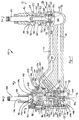
Referring now to the drawings in which like reference
numerals designate like or corresponding parts throughout
the several views, there is shown in Figure 1 an anti-scald
faucet system which is designated generally by reference
numeral 10. Faucet system 10 comprises a cold water control
valve 12, a cold water supply conduit 14, a mixed water
supply conduit 16 and a hot water control valve 18. Cold
water control valve 12 is a conventional control valve
having a housing 22, a bonnet 24, a stem assembly 26 and a
valve assembly 28. Housing 22 is integrally formed with
conduits 14 and 16 and it defines a chamber 30 which
receives cold water from supply conduit 14 and supplies cold
water to mixed water supply conduit 16. Housing 22 defines
a threaded bore 32 which is open to chamber 30.
Bonnet 24 is threadingly received within bore 32 to
retain stem assembly 26 and valve assembly 28 within chamber
30. A seal 34 seals the interface between bonnet 24 and
housing 22. Bonnet 24 includes an exterior configuration 36
which is adapted to receive various components which locate
and secure faucet system 10 to the building structure of the
tub and/or shower with which faucet system 10 is being used
as well as decorative trim components. Bonnet 24 defines an
internal chamber 38 having a bushing within which stem
assembly 26 is located.
Stem assembly 26 comprises an outer stem 40 and an
inner stem 42. Outer stem 40 is located within chamber 38
and is retained within chamber 38 by interfacing with a
shoulder 44 formed by chamber 38. One end of outer stem 40
extends outwardly of bonnet 24 and is adapted to receive a
control knob (not shown). The interface between outer stem
40 and shoulder 44 also operates to retain inner stem 42 and
valve assembly 28 within chambers 38 and 30 as described
below. The opposite end of outer stem 40 or the end
disposed within chamber 38 provides the connection between
outer stem 40 and inner stem 42. Outer stem 40 defines a
slot 46 which accepts a tab 48 on inner stem 42 to
rotationally couple outer stem 40 with inner stem 42. Inner
stem 42 is a cup shaped component which is located within
chamber 38 between outer stem 40 and valve assembly 28. An
O-ring 50 seals the interface between inner stem 42 and
bonnet 24 to retain water within chamber 38. Inner stem 42
defines a chamber 52 which is in communication with chamber
38 through a plurality of holes 54. The end of inner stem
42 opposite to tab 48 is rotationally coupled to valve
assembly 28.
Valve assembly 28 is disposed within chamber 30 between
stem assembly 26 and a shoulder 56 defined in chamber 30 by
housing 22. Valve assembly 28 comprises a rotating ceramic
disk 58, a stationary ceramic disk 60 and a rubber seal 62.
Rotating ceramic disk 58 is rotatably secured to inner stem
42 and it defines a tear shaped aperture 64 which regulates
the amount of cold water that is allowed to pass through
valve assembly 28. Rotating ceramic disk 58 includes a
highly polished surface 66 for mating with stationary disk
60.
Stationary disk 60 is disposed adjacent to surface 66
of disk 58 and it includes a highly polished surface 68
which mates with surface 66 to form a fluid light connection
between the two surfaces. Stationary disk 60 defines a
generally circular aperture 70 which is positioned to align
with tear drop shaped aperture 64 of rotating ceramic disk
58. Stationary disk 60 is prohibited from rotating with in
chamber 30. Rubber seal 62 is disposed between stationary
disk 60 and shoulder 56 to prohibit fluid flow between
stationary disk 60 and shoulder 56. Thus, all fluid flow
through valve assembly 28 occurs through apertures 70 and
64. Retainer 72, integral with bonnet 24, surrounds disk
58, disk 60 and rubber seal 62 to maintain the concentric
alignment of these components during the rotation of
rotating ceramic disk 58.
The assembly of cold water control valve 12 is
accomplished by inserting valve assembly 28 within chamber
30 of housing 22, positioning stem assembly 26 within
chamber 30 and rotationally coupling it with valve assembly
28 and then threading bonnet 24 into bore 32 to secure the
components of the valve. In the alternative, stem assembly
26 can be positioned within chamber 38 of bonnet 24, mating
valve assembly 28 with inner stem 42 and inserting this
assembly into bore 32 of housing 22 and threadingly engaging
bonnet 24 with bore 32 of housing 22. The threading
engagement between bonnet 24 and housing 22 permits the
compression of seal 34 and rubber seal 62. Once assembled,
valve assembly 28 operates to meter the cold water flow
through valve assembly 28 from a blocked flow position to a
full open position based on the rotational position of
rotating ceramic disk 58 with respect to stationary ceramic
disk 60. When rotating disk 58 is positioned such that
aperture 70 of disk 60 is aligned with a solid portion of
disk 58 and not a portion of aperture 64, fluid flow will be
blocked due to the fluid tight engagement of surface 66 with
surface 68. Rotation of outer stem 40 causes rotation of
inner stem 42 which causes rotation of disk 58 to bring a
portion of tear drop shaped aperture 64 in alignment with
aperture 70 and thus allow fluid flow through valve assembly
28. The tear drop shape of aperture 64 permits an increase
in the fluid flow through valve assembly 28 with the
continued rotation of outer stem 40.
Cold water supply conduit 14 is integrally formed with
mixed water supply conduit 16 as well as being integrally
formed with housing 22 of cold water control valve 12 and
integrally formed with hot water control valve 18. Mixed
water supply conduit 16 is in flow communication with a
mixing port 74 which is to be connected to the supply pipe
for the tub and/or shower.
Referring now to Figures 1-3, hot water control valve
18 comprises a housing 78, a pressure balancer 80, a fluid
distribution plate 82, a gasket 84, a stationary ceramic
disk 86, a rotating ceramic disk 88, a stem assembly 90, a
bonnet 92 and a high temperature adjustment control 94.
Housing 78 is integrally formed with conduits 14 and 16 and
it defines a chamber 96 which receives cold water from a
source of cold water (not shown) through a cold water port
98, receives hot water from a source of hot water (not
shown) through a hot water port 100, supplies cold water to
supply conduit 14 for feeding cold water control valve 12
and supplies temperature limited hot water to mixed water
supply conduit 16 for delivery to mixing port 74.
Pressure balancer 80 is located within chamber 96 of
housing 78 between cold water port 98 and supply conduit 14
and between hot water port 100 and mixed water supply
conduit 16. Pressure balancer 80 is comprised of a first
plastic section 102, a second plastic section 104 and a
poppet assembly 106. Pressure balancer 80 is seated against
a shoulder 108 formed by housing 78 within chamber 96. A
pair of seals 110 and 112 seal the connection between cold
water port 98 and section 102 of pressure balancer 80 and
between hot water port 100 and section 104 of pressure
balancer 80. Poppet assembly 106 is disposed within a
chamber formed by sections 102 and 104. Poppet assembly 106
comprises a one-piece poppet unit 116 and a diaphragm 118.
Poppet unit 116 is attached to diaphragm 118 by over
moulding diaphragm 118 to an annular shoulder 120 formed on
poppet unit 116.
Diaphragm 118 includes an annular bead 126 which is
sandwiched between sections 102 and 104 to provide a fluid
tight connection separating the chamber defined by sections
102 and 104 into a cold water chamber 128 and a hot water
chamber 130. Cold water chamber 128 includes an input
portion 132 which is in communication with cold water port
98, a central portion 134 and an outlet portion 136. Outlet
portion 136 is in direction communication with cold water
supply conduit 14 to provide the cold water supply to cold
water control valve 12. Similarly, hot water chamber 130
includes an input portion 138, a central portion 140 and an
outlet portion 142. Poppet unit 116 includes a cold water
poppet 144 disposed within central portion 134 and a hot
water poppet 146 disposed within central portion 140.
Poppets 144 and 146 are integral with the central portion of
poppet unit 116 which mounts diaphragm 118. A bore 148
extends radially and axially through poppet 144 to allow
cold water to flow from behind poppet 144 and section 102.
Likewise, a bore 150 extends radially and axially through
poppet 146 to allow hot water to flow from behind poppet 146
and section 104. Poppet 144 controls the fluid flow of cold
water by opening and closing a cold water port 152 located
within central portion 134 and poppet 146 controls the fluid
flow of hot water by opening and closing a hot water port
154 located within central portion 140.
When cold water pressure and hot water pressure are
equal, diaphragm 118 is centrally positioned between
chambers 128 and 130 allowing an equal amount of cold water
and hot water to flow through pressure balancer 80. Cold
water is supplied through cold water port 98 into input
portion 132, through central portion 134 and port 152 and
finally out outlet portion 136. In a similar manner, hot
water is supplied through hot water port 100 into input
portion 138, through central portion 140 and port 154 and
out outlet portion 142. Should the cold water pressure
decrease, poppet assembly 106 is urged to the left as shown
in Figure 1 or toward cold water chamber 128. This movement
reduces the opening of hot water port 154 and increases the
opening of cold water port 152 thereby maintaining the ratio
of hot and cold water to stabilise the temperature of the
mixed water being supplied through mixing port 74. In a
similar manner, should the hot water pressure decrease,
poppet assembly 106 is urged to the right as shown in Figure
1 or toward hot water chamber 130. This movement reduces
the opening of cold water port 152 and increases the opening
of hot water port 154 thereby maintaining the ratio of the
flow of hot and cold water to stabilise the temperature of
the mixed water being supplied through mixing port 74. The
details and function of pressure balancer 80 are described
in more detail in U.S. Patent 5,501,244.
Fluid distribution plate 82 is disposed within chamber
96 with one face positioned adjacent to pressure balancer
80. Fluid distribution plate 82 includes a cold water inlet
passage 160 which is in communication with outlet portion
136 of section 102 of balancer 80 and which supplies cold
water to high temperature adjustment control 94. Fluid
distribution plate 82 includes a hot water passage 162 which
is in communication with outlet portion 142 of section 104
of balancer 80 and which supplies hot water to the hot water
control portion of hot water control valve 18. A gasket 164
seals the connection between distribution plate 82 and
balancer 80, the connection between passage 160 and outlet
portion 136 and the connection between passage 162 and
outlet portion 142. Fluid distribution plate 82 also
includes a cold water outlet passage 166 which receives cold
water from high temperature adjustment control 94 and which
supplies cold water to the cold water control portion of hot
water control valve 18. Gasket 84 is disposed adjacent to
the opposite face of distribution plate 82 and operates to
seal the interface between plate 82 and stationary ceramic
disk 86. Gasket 84 defines a cold water bore 168 in
communication with passage 166 of plate 82 and a hot water
bore 170 in communication with passage 162.
Referring now to Figure 3, stationary ceramic disk 86
is positioned on top of gasket 84 as shown in Figure 1.
Ceramic disk 86, includes a radially extending tab 172 which
engages high temperature adjustment control 94 to prohibit
rotation of disk 86. Ceramic disk 86 defines a cold water
passage 174 which is in communication with cold water bore
168 of gasket 84 and a hot water passage 176 which is in
communication with hot water bore 170 of gasket 84.
Stationary ceramic disk 86 includes a highly polished
surface 178 for mating with rotating ceramic disk 88.
Rotating ceramic disk 88 is disposed adjacent to
surface 178 of disk 86 and it includes a highly polished
surface 180 which mates with surface 178 to form a fluid
tight connection between the two surfaces. Rotating ceramic
disk 88 defines a cold water tear drop shaped aperture 182
which regulates the amount of cold water that is allowed to
flow through control valve 18. Tear drop shaped aperture
182 is radially positioned to align with cold water passage
174 of disk 86 upon rotation of disk 88. Rotating ceramic
disk 88 also defines a hot water tear drop shaped aperture
184 which regulates the amount of hot water that is allowed
to flow through control valve 18. Tear drop shaped aperture
184 is radially positioned to align with hot water passage
176 of disk 86 upon rotation of disk 88. Stationary disk 86
and rotating disk 88 thus form a hot water valve assembly
for hot water control valve 18.
Referring now to Figure 1, stem assembly 90 comprises
an inner stem 186 and an outer stem 188. Inner stem 186 is
positioned adjacent to rotating ceramic disk 88 and is
rotatably coupled to disk 88. Inner stem 186 defines a
chamber 190 which receives cold water from tear drop shaped
aperture 182 and hot water from tear drop shaped aperture
184 and directs this mixture of hot and cold water to mixed
water supply conduit 16. Inner stem 186 also defines a tab
192 which engages a slot 194 in outer stem 188 to
rotationally couple inner stem 186 with outer stem 188.
Outer stem 188 extends outward of control valve 18 and is
adapted at the end opposite to slot 194 to accept a control
knob (not shown).
Bonnet 92 is positioned over stem assembly 90 and
defines an open bore 196 having a bushing which accepts stem
assembly 90. A seal 198 seals the interface between bonnet
92 and stem assembly 90 to retain water within chamber 190.
Bonnet 92 is secured to housing 78 using a plurality of
fasteners 200 which allow for the assembly and disassembly
of control valve 18 for maintenance and the like. A gasket
202 seals the interface between bonnet 92 and housing 78.
Referring now to Figures 4 and 5, high temperature
adjustment control 94 comprises a housing 204, a valve seat
206, a needle valve 208 and a retainer 210. Housing 204 is
integrally formed with bonnet 92 and defines a through bore
212 having a threaded end 214. Valve seat 206 is an
integral part of fluid distribution plate 82 and is in
communication with a cold water flow passage 216 extending
through plate 82. Passage 216 is in communication with cold
water inlet passage 160 at one end and with cold water
outlet passage 166 at the opposite end. Needle valve 208 is
threadingly received by retainer 210 which in turn is
threadingly received by threaded end 214 of bore 212. A
seal 218 is disposed between housing 204 and needle valve
208 to retain water within bore 212. One end of needle
valve 208 extends into passage 216 and includes a tapered
portion 220 which regulates the amount of cold water allowed
to flow through passage 216 depending on the axial position
of tapered portion 220 with respect to valve seat 206. The
axial position of tapered portion 220 with respect to valve
seat 206 is adjusted by rotating needle valve 208 due to the
threaded connection between needle valve 208 and retainer
210. Needle valve 208 extends upward through gasket 84,
through bore 212 and through threaded end 214 such that the
end of needle valve 208 opposite to tapered portion 220
extends outwardly from housing 204. The end of needle valve
208 which extends out from housing 204 is adapted to be
assembled to a control knob 222 to facilitate the rotation
and thus adjustment of high temperature adjustment control
94.
Referring now to Figures 1-5, the assembly of hot water
control valve 18 is accomplished by inserting pressure
balancer 80 within chamber 96 followed by gasket 164 and
fluid distribution plate 82. Needle valve 208 is then
assembled with gasket 84 and this assembly is located
adjacent to distribution plate 82. Stationary ceramic disk
86 is positioned adjacent gasket 84 followed by rotating
ceramic disk 88 and stem assembly 90 which is rotatably
coupled to disk 88. Bonnet 92 is then assembled over stem
assembly 90 and needle valve 208 and secured in position by
fasteners 200. Seal 218 is inserted into bore 212 followed
by retainer 210 which threadably engages both housing 204
and needle valve 208. Finally, control device 222 is
assembled to needle valve 208. The disassembly of control
valve 18 is the reverse of the above described assembly
procedure thereby enabling total disassembly of hot water
control valve 18 for maintenance and repair after faucet
system 10 has been built into the shower or tub wall
structure.
Once assembled, hot water control valve 18 operates to
balance supply pressures for the hot and cold water for
maintaining mixed water temperature, operates to limit the
temperature of the hot water supplied to mixed water supply
conduit 16 and operates to meter the amount of hot water
supplied to mixed water supply conduit 16. The metering
function of control valve 18 is based on the rotational
position of rotating ceramic disk 88 with respect to
stationary ceramic disk 86 in the same manner as cold water
control valve 12. When rotating disk 88 is positioned such
that hot water passage 176 of stationary disk 86 and cold
water passage 174 of stationary disk 86 are aligned with a
solid portion of rotating disk 88 and not a portion of
apertures 184 and 182, respectively, fluid flow through
control valve 18 will be blocked due to the fluid tight
engagement of surfaces 178 and 180. The circumferential
position of cold water aperture 182 and hot water aperture
184 in relation to passages 174 and 176 is designed such
that upon rotation of disk 88, there is simultaneous
alignment between cold water aperture 182 and cold water
passage 174 and between hot water aperture 184 and hot water
passage 176. Rotation of outer stem 188 causes rotation of
inner stem 186 which causes rotation of disk 88 to bring a
portion of cold water tear drop shaped aperture 182 in
alignment with cold water passage 174 simultaneous to
bringing a portion of hot water tear drop shaped aperture
184 in alignment with hot water passage 176 and thus allow
fluid flow through control valve 18. The tear drop shape of
apertures 182 and 184 permit an increase in fluid flow
through control valve 18 with the continued rotation of
outer stem 188 while generally maintaining the mix ratio of
hot and cold water.
The cold water flowing through aperture 182 into
chamber 190 and the hot water flowing through aperture 184
into chamber 190 mix in chamber 190 to control the maximum
temperature of the mixed hot water being supplied to mixed
water supply conduit 16 which then mixes with cold water
from cold water control valve 12 to provide the desired
water temperature at mixing port 74. The amount of cold
water which is supplied to cold water aperture 182 is
controlled by high temperature adjustment control 94. The
rotation of needle valve 208 adjusts the opening between
tapered portion 220 of needle valve 208 and valve seat 206
to regulate the amount of cold water which is supplied to
chamber 190 and thus the temperature of the hot water
supplied to mixed water supply conduit 16. This hot water
temperature control and the pressure balancing system
described above both will function with only hot water
control valve 18 open. The opening of cold water control
valve 12 is not required for the operation of these two
controls offering both convenience and safety to the user
while the design for control valve 18 provides the
accessibility to these controls for maintenance and/or
repair.
Referring now to Figures 6-9, there is shown a faucet
system in accordance with the present invention which is
designated generally by the reference numeral 310. Faucet
system 310 is similar to faucet system 10 with the exception
being that the pressure balancing system is located remotely
from the control valves. The function and operation of
faucet system 310 is identical to the function and operation
of faucet system 10. Features in faucet assembly 310 which
are the same as those in faucet assembly 10 are given the
same reference number. Features in faucet assembly 310
which are similar to those in faucet assembly 10 have
reference numerals which are increased by 300. Faucet
system 310 comprises cold water control valve 312, cold
water supply conduit 14, mixed water supply conduit 16, a
hot water control valve 318 and a pressure balancer 380.
Cold water control valve 312 is similar to cold water
control valve 12 except that housing 22 is replaced with
housing 322. Housing 322 is similar to housing 22 except
that housing 322 includes cold water port 98.
Hot water control valve 318 comprises a housing 378, a
gasket 384, a stationary ceramic disk 386, a rotating
ceramic disk 388, a stem assembly 390, a bonnet 392 and a
high temperature adjustment control 394. Housing 378 is
integrally formed with conduits 14 and 16 and it defines a
chamber 396 which receives cold water from cold water supply
conduit 14 which receives water through cold water port 98,
receives hot water from a source of hot water (not shown)
through hot water port 100 and supplies temperature limited
hot water to mixed water supply conduit 16 for delivery to
mixing port 74.
Stationary ceramic disk 386 is positioned on top of
gasket 384 which is positioned within chamber 396 against a
shoulder 356 formed by housing 378. Gasket 384 defines cold
water bore 168 in communication with cold water port 98 and
hot water bore 170 in communication with hot water port 100.
Cold water bore 168 is also in communication with cold water
passage 174 of disk 386 and hot water bore 170 is also in
communication with hot water passage 176 of disk 386.
Stationary ceramic disk 386 includes polished surface 178
for mating with rotating ceramic disk 388.
Rotating ceramic disk 388 is disposed adjacent surface
178 of disk 386 and it includes polished surface 180 which
mates with surface 178 to form the fluid tight connection.
Rotating disk 388 defines cold water tear drop shaped
aperture 182 and hot water tear drop shaped aperture 184
which mate with passages 174 and 176, respectively, as
described above.
Stem assembly 390 comprises an inner stem 486 and an
outer stem 488. Inner stem 486 is positioned adjacent to
rotating ceramic disk 388 and is rotatably coupled to disk
388. Inner stem 186 defines a chamber 352 which receives
cold water from aperture 182 and hot water from aperture 184
and directs this mixture of hot and cold water to mixed
water supply conduit 16 through a plurality of holes 354.
Inner stem 486 defines a tab 492 which engages a slot 494 in
outer stem 488 to rotationally couple inner stem 486 with
outer stem 488. Outer stem 488 extends outward of control
valve 318 and is adapted at the end opposite to slot 494 to
accept a control knob (not shown).
Bonnet 392 is positioned over stem assembly 390 and
defines a bore 496 having a bushing which accepts stem
assembly 390. A seal 498 seals the interface between bonnet
392 and stem assembly 390 to retain water within chamber
352. Bonnet 392 is secured to housing 378 using a threaded
connection similar to that described above for bonnet 24 of
cold water control valve 12. The threaded connection for
bonnet 392 also permits the disassembly of control valve 318
for maintenance and/or repair. A gasket 502 seals the
interface between bonnet 392 and housing 378.
Referring now to Figures 7 and 8, high temperature
adjustment control 394 comprises a housing 504, a valve seat
506, needle valve 208 and retainer 210. Housing 504 is
integrally formed with housing 378 and defines a through
bore 512 having threaded end 214. Valve seat 506 is an
integral part of housing 378 and is in communication with a
cold water flow passage 516 extending through housing 378.
Passage 516 is in communication with cold water supply
conduit 14 and port 98 at one end and with cold water
passage 174 of stationary disk 386 at its opposite end.
Needle valve 208 is threadingly received by retainer 210
which in turn is threadingly received by threaded end 214 of
bore 512. Seal 218 is disposed between housing 504 and
needle valve 208 to retain water within bore 512. Identical
to adjustment control 94, the axial position of tapered
portion 220 with respect to valve seat 506 is adjusted by
rotating needle valve 208 due to the threaded connection
between needle valve 208 and retainer 210.
The function and operation of high temperature
adjustment control 394 is identical to that of control 94 in
that it operates to limit the hot water temperature supplied
to mixed water supply conduit 16. Also, identical to faucet
system 10, the high temperature limit control feature of
faucet system 310 functions with only hot water control
valve 318 being turned on due to the direct supply of cold
water from cold water port 98 to cold water supply conduit
14 to hot water control valve 318.
Referring now to Figure 9, pressure balancer 380
includes pressure balancer 80, an inlet housing 520 and an
outlet housing 522. Pressure balancer 80, described above
is disposed within a chamber 524 defined by inlet housing
520. Inlet housing 520 defines a cold water inlet 526 which
is in communication with a source of cold water supply (not
shown) at one end and with input portion 132 of chamber 128
at the opposite end. Inlet housing 520 also defines a hot
water inlet 528 which is in communication with a source of
hot water supply (not shown) at one end and with input
portion 138 of hot water chamber 130 at the opposite end.
Outlet housing 522 is attached to inlet housing 520 and
includes a cold water outlet 530 and a hot water outlet 532.
Cold water outlet 530 is in communication with outlet
portion 136 of chamber 128 through a tubular conduit 534 at
one end and with cold water port 98 at the opposite end
through a water pipe 536 (Figure 6). Hot water outlet 532
is in communication with outlet portion 142 of chamber 130
through a tubular conduit 538 at one end and with hot water
port 100 at the opposite end through a water pipe 540
(Figure 6).
The function and operation of pressure balancer 380 is
identical to that of pressure balancer 80 assembled into hot
water control valve 18 as described above.
Referring now to Figures 10 and 11, a valve assembly in
accordance with another embodiment of the present invention
which is designated generally by the reference numeral 600.
Features in valve assembly 600 which are the same as those
in control valve 18 are given the same reference number.
Features in valve assembly 600 which are similar to those in
control valve 18 have reference numerals which are increased
by 600. Valve assembly 600 is designed to replace the
various components of hot water control valve 18 to change
control valve 18 from a ceramic valve to a rubber and
stainless steel valve. Valve assembly 600 comprises a fluid
distribution plate 682, a rotating disk 688, an inner stem
786 and a housing 804. Fluid distribution 682 plate is
designed to be positioned with one face adjacent to pressure
balancer 80. Fluid distribution plate 682 includes a cold
water inlet passage 760 which is in communication with
outlet portion 136 of section 102 of pressure balancer 80
and which supplies cold water to housing 804. Fluid
distribution plate 682 includes a hot water passage 762
which is in communication with outlet portion 142 of section
104 of pressure balancer 80 and which supplies hot water for
valve assembly 600. A gasket 764 seals the connection
between distribution plate 682 and balancer 80, the
connection between passage 760 and outlet portion 136 and
the connection between passage 762 and outlet portion 142.
Fluid distribution plate 682 also includes a cold water
outlet passage 766 which receives cold water from housing
804 and which supplies cold water for valve assembly 600.
The upper end of passage 766 houses a spring 850 and a
rubber seal 852. Spring 850 biases rubber seal 852 away
from plate 682 and against rotating disk 688. The upper end
of passage 762 houses a spring 854 and a rubber seal 856.
Spring 854 biases rubber seal 856 away from plate 682 and
against rotating disk 688. Rubber seals 852 and 856 and
plate 682 eliminate the need for having a stationary disk
similar to disk 86.
Rotating disk 688 is disposed adjacent to plate 682 and
seals 852 and 856. Disk 688 defines cold water tear drop
shaped aperture 182 which regulates the amount of cold water
that is allowed to flow through valve assembly 600. Tear
drop shaped aperture 184 is radially positioned to align
with cold water outlet passage 766 upon rotation of disk
688. Rotating disk 688 also defines hot water tear drop
shaped aperture 184 which regulates the amount of hot water
that is allowed to flow through valve assembly 600. Tear
drop shaped aperture 184 is radially positioned to align
with hot water passage 762 upon rotation of disk 688.
Rotating disk 688 is secured to inner stem 786 for rotation
therewith. Inner stem 786 defines a cold water tear drop
shaped aperture 782 which aligns with tear drop shaped
aperture 182. Inner stem 786 defines a hot water aperture
784 which aligns with tear drop shaped aperture 184. Inner
stem 786 also defines chamber 190 for providing mixed hot
water from apertures 182, 782, 184 and 784. The upper
portion of inner stem 786 is similar to inner stem 186.
Housing 804 defines a through bore 812 which accepts
needle valve 208. Housing 804 also defines a cold water
flow passage 816. Passage 816 is in communication with cold
water inlet passage 760 at one end and with cold water
outlet passage 766 at the opposite end. Fluid distribution
plate 682 defines valve seat 206 and the function and
operation of needle valve 208 which is threadingly received
in a bonnet (not shown), valve seat 206 and housing 804 are
identical to that described above for high temperature
adjustment control 94. Housing 804 is disposed adjacent to
fluid distribution plate 682 with a seal 858 sealing the
interface between the two components. A valve similar to
valve assembly 600 is described in better detail in U.S.
Patent No. 5,501,244.