RU2042074C1 - Mixing cock - Google Patents
Mixing cock Download PDFInfo
- Publication number
- RU2042074C1 RU2042074C1 SU914895815A SU4895815A RU2042074C1 RU 2042074 C1 RU2042074 C1 RU 2042074C1 SU 914895815 A SU914895815 A SU 914895815A SU 4895815 A SU4895815 A SU 4895815A RU 2042074 C1 RU2042074 C1 RU 2042074C1
- Authority
- RU
- Russia
- Prior art keywords
- inlet
- water
- openings
- hot
- holes
- Prior art date
Links
Images


Classifications
-
- F—MECHANICAL ENGINEERING; LIGHTING; HEATING; WEAPONS; BLASTING
- F16—ENGINEERING ELEMENTS AND UNITS; GENERAL MEASURES FOR PRODUCING AND MAINTAINING EFFECTIVE FUNCTIONING OF MACHINES OR INSTALLATIONS; THERMAL INSULATION IN GENERAL
- F16K—VALVES; TAPS; COCKS; ACTUATING-FLOATS; DEVICES FOR VENTING OR AERATING
- F16K11/00—Multiple-way valves, e.g. mixing valves; Pipe fittings incorporating such valves
- F16K11/02—Multiple-way valves, e.g. mixing valves; Pipe fittings incorporating such valves with all movable sealing faces moving as one unit
- F16K11/08—Multiple-way valves, e.g. mixing valves; Pipe fittings incorporating such valves with all movable sealing faces moving as one unit comprising only taps or cocks
- F16K11/087—Multiple-way valves, e.g. mixing valves; Pipe fittings incorporating such valves with all movable sealing faces moving as one unit comprising only taps or cocks with spherical plug
Abstract
Description
Изобретение относится к смесительным кранам с одной рукояткой, управляемой, в частности, сферическим клапанным элементом. The invention relates to mixing cranes with one handle, controlled, in particular, by a spherical valve element.
Известен смесительный кран [1] содержащий сферический клапанный элемент, снабженный направляющим механизмом, обеспечивающим перемещение сферического клапанного элемента в двух различных направлениях и выполненный с отверстиями, сообщающимися с отверстиями для впуска горячей и холодной воды, снабженными трубчатыми уплотнениями, и с отверстием для выпуска смешанной воды, причем упомянутые отверстия для впуска и выпуска воды расположены в полусферическом седле в неподвижной части корпуса крана для регулирования смешивания горячей и холодной воды и общего потока смешанной воды. Пропорция между холодной и горячей водой, а также скорость потока регулируются в результате соответствующего перемещения сферического клапанного элемента, установленного в полости корпуса крана. Широкое использование смесительного крана с шаровым клапаном гарантируется многими его преимуществами. Known mixing valve [1] containing a spherical valve element provided with a guide mechanism for moving the spherical valve element in two different directions and made with holes in communication with the holes for the inlet of hot and cold water, equipped with tubular seals, and with an opening for the release of mixed water wherein said water inlet and outlet openings are located in a hemispherical saddle in a fixed part of the valve body to control the mixing of hot and cold boat water and the total flow of mixed water. The proportion between cold and hot water, as well as the flow rate are regulated as a result of the corresponding movement of the spherical valve element installed in the cavity of the valve body. The widespread use of a mixing valve with ball valve is guaranteed by its many advantages.
Однако ему свойственны недостатки, которые связаны главным образом с жесткими ограничениями диаметра трубчатых уплотнений для впускного отверстия, изготовленных из эластомерного материала, через которое проходит горячая и холодная вода. Следовательно, такой смесительный кран имеет ограниченную скорость потока воды. Более того, он имеет ограниченную зону комфортности, что означает ограниченное движение рукоятки, которая обеспечивает срабатывание шарового клапана для холодной и горячей воды. Отмеченные выше недостатки можно устранить за счет увеличения диаметра эластомерных трубчатых уплотнений, однако практическая реализация этой идеи связана с большими трудностями, поскольку по мере увеличения диаметра упомянутых уплотнений неизбежна их размерная стабильность и они становятся более склонными к возникновению через них утечки и могут выйти из строя в результате возникновения большего трения между поверхностями шарового клапана и трубчатых уплотнений при перемещении шарового клапана. However, it is characterized by disadvantages, which are mainly associated with severe restrictions on the diameter of the tubular seals for the inlet made of an elastomeric material through which hot and cold water passes. Therefore, such a mixing tap has a limited water flow rate. Moreover, it has a limited comfort zone, which means a limited movement of the handle, which ensures the operation of the ball valve for cold and hot water. The drawbacks noted above can be eliminated by increasing the diameter of the elastomeric tubular seals, however, the practical implementation of this idea is associated with great difficulties, since as the diameter of the mentioned seals increases, their dimensional stability is inevitable and they become more prone to leakage through them and may fail the result of greater friction between the surfaces of the ball valve and the tubular seals when moving the ball valve.
Целью изобретения является создание крена улучшенной конструкции на основе известных способов регулирования с более высокой скоростью потока, повышенной зоной комфортности и более низким уровнем шума при сохранении всех прочих преимуществ существующего смесителя. The aim of the invention is to create a roll of improved design based on known control methods with a higher flow rate, increased comfort zone and lower noise while maintaining all the other advantages of the existing mixer.
Цель достигается тем, что смесительный кран выполнен по меньшей мере с одним дополнительным отверстием с трубчатым уплотнением для впуска горячей воды и по меньшей мере с одним дополнительным отверстием с трубчатым уплотнением для впуска холодной воды, причем по меньшей мере два из отверстий для впуска горячей и холодной воды расположены вдоль окружности полусферического седла, а в сферическом клапанном элементе отверстие для впуска воды выполнено продолговатой формы для одновременного сообщения по меньшей мере с двумя из впускных отверстий седла, остальные же отверстия для впуска горячей и холодной воды расположены по окружности полусферического седла, смещенной относительно уровня расположения первых двух отверстий для впуска холодной и горячей воды на расстоянии, не превышающем половины внутреннего диаметра трубчатых уплотнений, установленных в отверстиях. The goal is achieved in that the mixing valve is made with at least one additional hole with a tubular seal for the inlet of hot water and at least one additional hole with a tubular seal for the inlet of cold water, and at least two of the holes for the inlet of hot and cold water are located along the circumference of the hemispherical seat, and in the spherical valve element, the water inlet hole is oblong in shape for simultaneous communication with at least two of the inlet ports from ERSTU seat, and the remaining openings for the inlet of hot and cold water are located on the circumference of the hemispherical seat, offset from the location of the level of the first two holes for the inlet of hot and cold water at a distance not exceeding half of the internal diameter of the tubular seals mounted in openings.
Кроме того, поскольку в кране имеется как минимум четыре, а не два отверстия для впуска воды, то эти отверстия можно располагать по окружности седла со значительно большим углом (180о), который в некоторых случаях может достигать 360о.Furthermore, because the tap has at least four rather than two openings for inlet of water, these holes can be arranged along the circumference of the saddle with a significantly large angle (about 180), which in some cases may reach about 360.
Предпочтительно, чтобы в отверстии для впуска воды в подвижном сферическом клапанном элементе были установлены перегородки. С помощью такой конструкции можно избежать вероятности того, что трубчатые уплотнения отверстий для впуска воды будут впрессовываться во внутреннюю часть шарового клапанного элемента под воздействием давления воды и тем самым разрушаться в результате врезания сферического клапанного элемента в поверхность трубчатого уплотнения в момент его вращения. Preferably, baffles are installed in the water inlet in the movable spherical valve member. With this design, it is possible to avoid the possibility that the tubular seals of the water inlet openings will be pressed into the inside of the spherical valve element under the influence of water pressure and thereby be destroyed by cutting the spherical valve element into the surface of the tubular seal at the time of its rotation.
На фиг. 1 изображен смесительный кран в разрезе; на фиг. 2 вид А на фиг. 1; на фиг. 3 сферический клапанный элемент в изометрии; на фиг. 4 направляющий элемент в изометрии; на фиг. 5 вариант выполнения смесительного крана в разрезе; на фиг. 6 вид Б на фиг. 5 (сферический клапанный элемент и крышка сняты); на фиг. 7 сферический клапанный элемент, показанный на фиг. 5, в изометрии; на фиг. 8 вариант выполнения сферического клапанного элемента в изометрии; на фиг. 9 вариант выполнения корпуса крана вместе с полусферическим седлом без сферического клапанного элемента и крышки, вид сверху; на фиг. 10 разрез В-В и Г-Г на фиг. 9; на фиг. 11-15 изображены варианты отверстий, расположенных в сферическом клапанном элементе, показанном на фиг. 10; на фиг. 16 вариант выполнения корпуса смесительного крана вместе с полусферическим седлом без сферического клапанного элемента и крышки, вид сверху; на фиг. 17 вариант выполнения корпуса смесительного крана вместе с полусферическим седлом без сферического клапанного элемента и крышки, вид сверху. In FIG. 1 shows a mixing valve in section; in FIG. 2, view A in FIG. 1; in FIG. 3 spherical valve element in isometry; in FIG. 4 guiding element in isometry; in FIG. 5 embodiment of a mixing tap in section; in FIG. 6 view B in FIG. 5 (spherical valve element and cover removed); in FIG. 7, the spherical valve member shown in FIG. 5, in isometry; in FIG. 8 embodiment of a spherical valve element in isometry; in FIG. 9 embodiment of a crane body together with a hemispherical seat without a spherical valve element and cover, top view; in FIG. 10 a section BB and GG in FIG. nine; in FIG. 11-15 illustrate embodiments of openings located in the spherical valve member shown in FIG. 10; in FIG. 16 embodiment of the mixing valve body together with a hemispherical seat without a spherical valve element and cover, top view; in FIG. 17 embodiment of the mixing valve body together with a hemispherical seat without a spherical valve element and cover, top view.
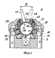
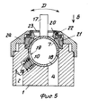
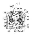
На фиг. 1 изображен корпус 1 крана с отверстиями 2 и 3 для впуска холодной и горячей воды и отверстием 4 для выпуска смеси смешанной воды. В неподвижной части корпуса 1 соответствующей формы установлен вспомогательный вкладыш 5, который образует полусферическое седло 6 для подвижного сферического клапанного элемента 7. Во вкладыше 5 выполнены сквозные отверстия 8-12. Отверстие 8 предназначено для смешанной воды, и оно сообщается с расположенным в корпусе 1 отверстием 4 для смешанной воды. Отверстия 9-12 сообщаются с впускными отверстиями 2 и 3, расположенными в корпусе 1, и предназначены для подачи горячей и холодной воды через каналы 13 и 14 соответственно. В каждом отверстии 9-12 установлены изготовленные из эластомерного материала трубчатые уплотнения 15. Каждое уплотнение 15 под воздействием пружины 16 смещается по направлению к внутренней стороне полусферического седла 6. In FIG. 1 shows a
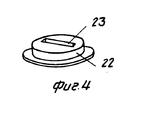
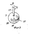
Изображенный на фиг. 3 подвижный сферический клапанный элемент 7 крана содержит шток 17 (обычно соединен с рукояткой, которая не показана), которым регулируют перемещение сферического клапанного элемента в двух различных направлениях: перемещение вдоль стрелки D фиг. 1 и 3 (чтобы регулировать скорость потока через клапан) и вращение вокруг оси штока 17 вдоль стрелки Е фиг. 3 (чтобы регулировать пропорцию смешивания горячей и холодной воды). В сферическом клапанном элементе 7 выполнены разгрузочное отверстие 18 для смешанной воды, которое сообщается с отверстием 8 для смешанной воды, и отверстие 19 продолговатой формы, через которое сферический клапанный элемент взаимодействует с отверстиями 9-12, причем в каждом отверстии 9-12 установлено уплотнение 15. Сферический клапанный элемент 7 удерживается в полусферическом седле 6 с помощью стопорного кольца 20 и промежуточного уплотнения 21. Все элементы крана, включая направляющую 22 штока вместе с прорезью 23 для размещения штока 17 сферического клапанного элемента, крепятся крышкой 24, которая навинчивается на корпус 1 крана. При этом шток 17 со своей направляющей 22 образуют направляющий механизм сферического клапанного элемента 7. Depicted in FIG. 3, the movable
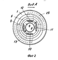
Другой функцией вкладыша 5 является гарантирование легкости изготовления впускных отверстий 9-12 под углами, которые можно просверливать с внешней стороны вкладыша с помощью стандартных режущих инструментов. Кроме того, даже в случае изготовления корпуса крана из латуни, вкладыш 5 можно изготавливать из пластмассы, которой можно придать нужную форму с помощью отверстий 9-12. Как ясно из фиг. 2, отверстия 9-12 для впуска воды, в которых удерживаются трубчатые уплотнения 15, разнесены по окружности полусферического седла 6. Впускные отверстия 9 и 10 сообщаются с впускным отверстием 2 для горячей воды через периферийный канал 13, а два других впускных отверстия 11 и 12 соединены с впускным отверстием 3 для холодной воды через периферийный канал 25. Another function of the
Во впускном отверстии 19 сферического клапанного элемента 7 установлены перегородки 26 с образованием ряда прямоугольных отверстий 27. Если наклонить шток 17 вправо (см. фиг. 1), то отверстие 10 открывает два смежных впускных отверстия, которыми могут быть либо впускные отверстия 9 и 10, чтобы обеспечить подачу только горячей воды, либо впускные отверстия 10 и 11, чтобы обеспечить подачу смешанной воды, либо впускные отверстия 11 и 12. При этом размер продолговатого отверстия 19 должен быть равным по меньшей мере внутреннему диаметру трубчатого уплотнения плюс удвоенное расстояние между смежными отверстиями, то есть размер продолговатого отверстия 19 больше суммы удвоенного внутреннего диаметра трубчатого уплотнения, размещенного в отверстиях корпуса для впуска воды, и трехкратного расстояния между смежными отверстиями в корпусе. При нахождении в конкретных позициях отверстие 10 будет полностью открывать одно отверстие, а два смежных отверстия будут открываться лишь частично. При постепенном переходе от только холодной воды к только горячей необходимо обеспечить срабатывание двух впускных отверстий для холодной воды, после чего закрывают одно из отверстий для холодной воды, при этом одно отверстие для горячей воды начинает постепенно открываться.
Дальнейшее движение будет полностью перекрывать первое отверстие для холодной воды и полностью открывать первое отверстие для горячей воды. Затем второе отверстие для холодной воды будет постепенно и частично закрываться, а второе впускное отверстие для горячей воды будет постепенно открываться до того момента, когда будут открыты два отверстия для горячей воды. Further movement will completely block the first hole for cold water and fully open the first hole for hot water. Then, the second cold water opening will be gradually and partially closed, and the second hot water inlet will gradually open until two hot water openings are opened.
Таким образом, можно добиться плавного постепенного изменения температуры смешанной воды, которое будет пропорционально движению рукоятки. За счет соответствующего расположения отверстий можно добиться линейной зависимости температуры от позиции регулирующей рукоятки, которая соединена сферическим клапанным элементом. Предпочтительно, чтобы отверстие 19 вдоль окружности сферического клапанного элемента образовывалось несколькими небольшими отверстиями 27 (см. фиг. 3), чтобы исключить вероятность повреждения трубчатых уплотнений углами отверстия 27. Thus, it is possible to achieve a smooth gradual change in the temperature of the mixed water, which will be proportional to the movement of the handle. Due to the corresponding arrangement of the holes, a linear dependence of the temperature on the position of the control handle, which is connected by a spherical valve element, can be achieved. Preferably, the
В случае расположения впускных отверстий по окружности на угол 360о можно добиться максимально большой зоны комфортности. Однако в большинстве случае бывает достаточно располагать два отверстия горячей и холодной воды на угол менее 360о, следовательно, в данном случае уменьшается угол регулирования подвижным сферическим клапанным элементом.In the case of arranging the inlet openings around a circle at an angle of 360 °, it is possible to achieve the largest possible comfort zone. However, in most cases, it is sufficient to place two holes of hot and cold water at an angle of less than 360 ° , therefore, in this case, the angle of regulation of the movable spherical valve element is reduced.
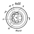
В показанном на фиг. 6 и 7 варианте изобретения трубчатые уплотнения для впускных отверстий непосредственно вставляются в корпус крана, так как угол в данном случае является таковым, что становится возможной механическая обработка отверстий с внутренней стороны. As shown in FIG. 6 and 7 of the invention, the tubular seals for the inlet openings are directly inserted into the valve body, since the angle in this case is such that it becomes possible to machine the openings from the inside.
На фиг. 6 видно, что отверстия для впуска воды расположены в полусферическом седле 6 по окружности под углом 180о. Выпускное отверстие 4 расположено в той части седла, которая не перекрывается впускными отверстиями. В результате этого угол движения сферического клапанного элемента от позиции горячей воды до позиции холодной воды равен половине угла по первому варианту выполнения крана.In FIG. 6 it is seen that the water inlet openings are located in a
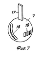
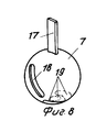
На фиг. 8 показана модификация показанного на фиг. 7 сферического клапанного элемента. На фиг. 8 видно, что сферический клапанный элемент 7 снабжен штоком 17 и выпускным отверстием 18, тогда как впускное отверстие 9 расположено в нижней части сферического клапанного элемента 7. Благодаря этому открытие крана осуществляется в результате наклона штока 17 с таким расчетом, чтобы впускные отверстия 19 перемещались снизу вверх, а не сверху вниз, как это происходит в случае с вариантом выполнения сферического клапанного элемента, показанного на фиг. 7. Кроме того, отверстие 19 выполнено сплошным, а не усилено ребрами. In FIG. 8 shows a modification of FIG. 7 spherical valve element. In FIG. Figure 8 shows that the
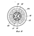
На фиг. 9 и 10 показан еще один вариант выполнения крана. По этому варианту вкладыш выполнен в виде патрона 29 и вставляется в корпус 30 в результате раздвижения соответствующих уплотнений и между ними. Фиксирующую крышку 31 можно устанавливать и закреплять на внешней стороне корпуса 30. Канал 32 расположен между корпусом 30 и патроном 29 и находится в гидравлическом сообщении с выпускным каналом 33, который расположен в направлении вниз, как показано на фиг. 10, или с внешней стороны корпуса 30. Смешанная вода входит в канал 32, через разгрузочное отверстие 34 в сферический клапанный элемент 35 и проходит дальше через канал 36 корпуса патрона 28. В патроне 29 выполнено центральное впускное отверстие 37 для горячей воды, которое соединено с впускным отверстием 38 корпуса 30 и с впускными отверстиями 39 и 40. In FIG. 9 and 10 show another embodiment of the crane. In this embodiment, the liner is made in the form of a
Боковое впускное отверстие 41 для холодной воды, концентричное центральному отверстию 37, соединено с впускными отверстиями 42 и 43 для холодной воды. Между донной или нижней частью корпуса 30 и патроном 29 образовано пространство 44, которое сообщается с впускным отверстием 45 для холодной воды в корпусе 30 и с отверстием 41 патрона 29. The lateral cold water inlet 41 concentric to the
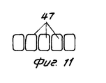
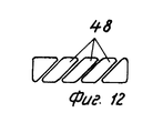
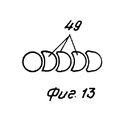
Находящиеся внутри патрона 29 элементы можно сделать симметричными, чтобы в двух кранах в одном случае образовывался через отверстие 37 центральный проход, соединенный с источником горячей воды, а в другом случае этот же центральный проход через отверстие 37 будет соединяться с источником холодной воды. Это важно в тех случаях, когда краны устанавливаются на двух поверхностях общей центральной стенки с использованием одной и той же системы трубопровода как для холодной, так и горячей воды. Впускные отверстия 39-43 располагаются по окружности в диапазоне от 180 до 360о. Как уже упоминали выше, если расположенное в сферическом клапанном элементе 35 отверстие 46 невозможно расчленить, как отверстие 19, показанное на фиг. 7, то рекомендуется установить в этом отверстии перегородки, образующие несколько небольших окон, которые могут иметь различную конфигурацию, например упомянутое отверстие может представлять собой несколько прямоугольников 47, которые показаны на фиг. 11, или несколько наклонных окон 48, показанных на фиг. 12, или окна могут быть криволинейной формы (фиг. 13, окна 49).The elements inside the
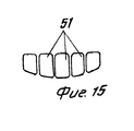
Кроме того, линия расположения упомянутых окон может быть прямой (см. фиг. 11 и 13) или изогнутой, например линией, на которой расположены окна 50 (см. фиг. 14). Как видно на фиг. 15, окна 51 могут иметь различную длину. За счет оптимального выбора формы упомянутых отверстий можно получить максимально линейную кривую управления и регулирования для температуры, например можно добиться того, чтобы любое изменение в угловой позиции элемента регулирования было пропорционально повышению или понижению температуры смешанной воды. In addition, the location line of said windows can be straight (see FIGS. 11 and 13) or curved, for example, the line on which
В показанных на фиг. 2, 6 и 9 кранах для каждого отверстия для впуска холодной и горячей воды имеется по два отверстия. Однако изобретение предусматривает возможность использования более двух отверстий для подачи горячей и холодной воды. As shown in FIG. 2, 6 and 9 taps for each hole for the inlet of cold and hot water there are two holes. However, the invention provides the possibility of using more than two holes for supplying hot and cold water.
Как видно из фиг. 16, полусферическая поверхность 52 вкладыша 53 устанавливается в корпусе 54, и эта поверхность снабжена тремя отверстиями 55-57 для горячей воды, которые находятся в гидравлическом сообщении с общим впускным каналом 57. Подобным же образом три других отверстия 59-61 находятся в гидравлическом сообщении с каналом 62. As can be seen from FIG. 16, the
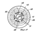
На фиг. 17 показан вариант выполнения крана, специально предназначенного для тех областей практического использования, в которых горячая вода подается при значительно меньшем давлении, чем холодная, что очень типично для систем, в которых используются газовые подогреватели воды. In FIG. 17 shows an embodiment of a faucet specifically designed for those areas of practical use in which hot water is supplied at a significantly lower pressure than cold, which is very typical for systems that use gas water heaters.
В этом варианте полусферическое седло 63 вкладыша 64, который вставляют в корпус 65, снабжено тремя отверстиями 66-68 для подачи горячей воды, которые соединены через канал 69. Холодная вода подается только через два отверстия 70 и 71, которые подобным же образом соединены через канал 72. Подобная конструкция крана дает возможность компенсировать более низкое давление горячей воды относительно давления холодной воды за счет образования несколько большего сечения впускных отверстий для горячей воды. Поскольку настоящее изобретение не предусматривает изменение геометрии резиновых уплотнений во впускном отверстии и соответствующих пружин упомянутых уплотнений, а также не предусматривает изменений геометрии направляющих элементов и уплотнений в верхней части шарового клапана, то многие компоненты кранов по настоящему изобретению будут идентичны элементам существующих кранов. In this embodiment, the
Несмотря на то, что в изобретении отверстия разнесены по окружности вокруг полусферической поверхности корпуса крана на одном уровне, суть изобретения применима и к тем впускным отверстиям, которые расположены близко от донной или нижней части крана. Различие в уровне центра впускных отверстий, двух отверстий горячей воды или двух отверстий холодной воды необходимо для того, чтобы не происходило одновременное открытие двух отверстий для горячей воды и двух отверстий для холодной воды и чтобы тем самым увеличивался угол регулирования объема. Предпочтительно, чтобы различие в уровне не превышало половины внутреннего диаметра трубчатых уплотнений. Выпускные отверстия 18, 34 сферического клапанного элемента можно располагать или придавать им форму относительно выпускных отверстий 8, 4 или 33 таким образом, чтобы уменьшать уровень шума крана, а также сделать более прямолинейным поток воды крана на протяжении всего диапазона регулирования температуры. Despite the fact that in the invention the holes are spaced around the circumference around the hemispherical surface of the crane body at the same level, the essence of the invention is applicable to those inlets that are located close to the bottom or bottom of the crane. The difference in the center level of the inlets, two hot water openings or two cold water openings is necessary in order to prevent the simultaneous opening of two hot water openings and two cold water openings and thereby increasing the volume control angle. Preferably, the difference in level does not exceed half the inner diameter of the tubular seals. The
В предлагаемом кране нужное направление сферического клапанного элемента достигается с помощью прорези в диске, расположенном в верхней части крана, однако изобретение учитывает возможность использования и любых иных средств направления движения шарового клапана. In the proposed valve, the desired direction of the spherical valve element is achieved using a slot in the disk located in the upper part of the valve, however, the invention takes into account the possibility of using any other means of guiding the movement of the ball valve.
Claims (14)
Applications Claiming Priority (1)
| Application Number | Priority Date | Filing Date | Title |
|---|---|---|---|
| PCT/US1989/004506 WO1991005967A1 (en) | 1989-10-10 | 1989-10-10 | Mixing valve with a ball control mechanism |
Publications (1)
| Publication Number | Publication Date |
|---|---|
| RU2042074C1 true RU2042074C1 (en) | 1995-08-20 |
Family
ID=22215288
Family Applications (1)
| Application Number | Title | Priority Date | Filing Date |
|---|---|---|---|
| SU914895815A RU2042074C1 (en) | 1989-10-10 | 1991-06-07 | Mixing cock |
Country Status (11)
| Country | Link |
|---|---|
| EP (1) | EP0456638B1 (en) |
| KR (1) | KR0182258B1 (en) |
| BG (1) | BG60180A3 (en) |
| BR (1) | BR8907840A (en) |
| DE (1) | DE68922114T2 (en) |
| DK (1) | DK174544B1 (en) |
| FI (1) | FI100126B (en) |
| NO (1) | NO177578C (en) |
| RO (1) | RO112911B1 (en) |
| RU (1) | RU2042074C1 (en) |
| WO (1) | WO1991005967A1 (en) |
Families Citing this family (2)
| Publication number | Priority date | Publication date | Assignee | Title |
|---|---|---|---|---|
| CN101644346B (en) * | 2009-08-26 | 2011-06-08 | 林必贵 | Two-way water outlet water nozzle valve |
| KR101854399B1 (en) | 2016-11-01 | 2018-05-03 | 한국전력기술 주식회사 | Fluid flow control device for the mitigation of thermal stratification phenomenon in mixing tee |
Family Cites Families (5)
| Publication number | Priority date | Publication date | Assignee | Title |
|---|---|---|---|---|
| US4108208A (en) * | 1977-02-22 | 1978-08-22 | Corpon P Von | Mixing tap |
| DE2904131C3 (en) * | 1979-02-03 | 1982-03-18 | Hans Grohe Gmbh & Co Kg, 7622 Schiltach | Mixing valve for liquids |
| DE3024518A1 (en) * | 1980-06-28 | 1982-01-28 | Hans Grohe Gmbh & Co Kg, 7622 Schiltach | MIXING VALVE FOR LIQUIDS |
| DE3419208A1 (en) * | 1984-05-23 | 1985-11-28 | Hans Grohe Gmbh & Co Kg, 7622 Schiltach | CONTROL INSERT FOR SANITARY MIXING FITTINGS |
| GB2180323A (en) * | 1985-09-17 | 1987-03-25 | Yang Tai Her | Faucet with spherical valve member |
-
1989
- 1989-10-10 BR BR898907840A patent/BR8907840A/en not_active IP Right Cessation
- 1989-10-10 EP EP89912202A patent/EP0456638B1/en not_active Expired - Lifetime
- 1989-10-10 DE DE68922114T patent/DE68922114T2/en not_active Expired - Fee Related
- 1989-10-10 RO RO147750A patent/RO112911B1/en unknown
- 1989-10-10 WO PCT/US1989/004506 patent/WO1991005967A1/en active IP Right Grant
- 1989-10-10 KR KR1019910700579A patent/KR0182258B1/en not_active IP Right Cessation
-
1991
- 1991-06-06 FI FI912731A patent/FI100126B/en not_active IP Right Cessation
- 1991-06-07 RU SU914895815A patent/RU2042074C1/en active
- 1991-06-07 NO NO912201A patent/NO177578C/en unknown
- 1991-06-10 BG BG94600A patent/BG60180A3/en unknown
- 1991-06-10 DK DK199101100A patent/DK174544B1/en not_active IP Right Cessation
Non-Patent Citations (1)
| Title |
|---|
| Патент США N 3915195, кл. F 16K 11/087, 1975. * |
Also Published As
| Publication number | Publication date |
|---|---|
| BG60180A3 (en) | 1993-11-15 |
| BR8907840A (en) | 1991-10-01 |
| DK174544B1 (en) | 2003-05-19 |
| DK110091A (en) | 1991-06-10 |
| KR920702883A (en) | 1992-10-28 |
| EP0456638A1 (en) | 1991-11-21 |
| WO1991005967A1 (en) | 1991-05-02 |
| EP0456638A4 (en) | 1992-01-02 |
| EP0456638B1 (en) | 1995-04-05 |
| JPH0652107B1 (en) | 1994-07-06 |
| DK110091D0 (en) | 1991-06-10 |
| FI100126B (en) | 1997-09-30 |
| NO912201L (en) | 1991-08-06 |
| DE68922114T2 (en) | 1995-09-28 |
| NO177578C (en) | 1995-10-11 |
| NO912201D0 (en) | 1991-06-07 |
| KR0182258B1 (en) | 1999-04-15 |
| FI912731A0 (en) | 1991-06-06 |
| NO177578B (en) | 1995-07-03 |
| DE68922114D1 (en) | 1995-05-11 |
| RO112911B1 (en) | 1998-01-30 |
Similar Documents
| Publication | Publication Date | Title |
|---|---|---|
| US4617965A (en) | Control insert for sanitary mixer valves | |
| US4979530A (en) | Modular valve assembly | |
| US3929283A (en) | Thermostatic mixing apparatus and a related method for regulating temperature | |
| US5355906A (en) | Pressure balanced mixing valve | |
| US7980268B2 (en) | Mixing valve | |
| US4676270A (en) | Single handle mixing valve incorporating a cartridge and a reversing piston | |
| US5904336A (en) | Valve assembly | |
| US5931181A (en) | Anti-scald faucet system | |
| US5507314A (en) | Mixer valve having a ball valve element | |
| US3448755A (en) | Non-scald mixing valve | |
| US20030234295A1 (en) | Single-lever thermostatic cartridge using ceramic disks | |
| EP0593489B1 (en) | Mixer valve having a ball valve element | |
| RU2158867C2 (en) | Detachable holder for ball valve of mixing cock | |
| RU2099620C1 (en) | Mixing water cock with ball valve | |
| RU2042074C1 (en) | Mixing cock | |
| US4495969A (en) | Mixing valve with water modulation sealing means | |
| RU2094684C1 (en) | Cartridge of ball valve for mixing tap and mixing tap | |
| EP0080018B1 (en) | Mixing valve | |
| US4315525A (en) | Mixing valve | |
| AU638949B2 (en) | Mixing valve with a ball control mechanism | |
| CA2000379C (en) | Mixing valve with a ball control mechanism | |
| JPS6128920Y2 (en) | ||
| KR20050078523A (en) | Water temperature and flow rate control valve of a water supply | |
| AU550476B2 (en) | Single control faucet | |
| EP0092545A4 (en) | Single control faucet. |