EP0885758B1 - Verfahren zum Betrieb eines Wärmetauschers im Abgasstrom einer Brennkraftmaschine für Kraftfahrzeuge - Google Patents
Verfahren zum Betrieb eines Wärmetauschers im Abgasstrom einer Brennkraftmaschine für Kraftfahrzeuge Download PDFInfo
- Publication number
- EP0885758B1 EP0885758B1 EP98108696A EP98108696A EP0885758B1 EP 0885758 B1 EP0885758 B1 EP 0885758B1 EP 98108696 A EP98108696 A EP 98108696A EP 98108696 A EP98108696 A EP 98108696A EP 0885758 B1 EP0885758 B1 EP 0885758B1
- Authority
- EP
- European Patent Office
- Prior art keywords
- phase
- valve
- exhaust gas
- heat exchanger
- combustion engine
- Prior art date
- Legal status (The legal status is an assumption and is not a legal conclusion. Google has not performed a legal analysis and makes no representation as to the accuracy of the status listed.)
- Expired - Lifetime
Links
Images
Classifications
-
- F—MECHANICAL ENGINEERING; LIGHTING; HEATING; WEAPONS; BLASTING
- F02—COMBUSTION ENGINES; HOT-GAS OR COMBUSTION-PRODUCT ENGINE PLANTS
- F02D—CONTROLLING COMBUSTION ENGINES
- F02D9/00—Controlling engines by throttling air or fuel-and-air induction conduits or exhaust conduits
- F02D9/04—Controlling engines by throttling air or fuel-and-air induction conduits or exhaust conduits concerning exhaust conduits
-
- B—PERFORMING OPERATIONS; TRANSPORTING
- B60—VEHICLES IN GENERAL
- B60H—ARRANGEMENTS OF HEATING, COOLING, VENTILATING OR OTHER AIR-TREATING DEVICES SPECIALLY ADAPTED FOR PASSENGER OR GOODS SPACES OF VEHICLES
- B60H1/00—Heating, cooling or ventilating devices
- B60H1/02—Heating, cooling or ventilating devices the heat being derived from the propulsion plant
- B60H1/14—Heating, cooling or ventilating devices the heat being derived from the propulsion plant other than from cooling liquid of the plant
- B60H1/18—Heating, cooling or ventilating devices the heat being derived from the propulsion plant other than from cooling liquid of the plant the air being heated from the plant exhaust gases
Definitions
- the invention relates to a method for operating an exhaust gas-heated heat exchanger in the exhaust gas flow of an internal combustion engine according to the generic term of claim 1.
- the method known from DE 195 00 473 A1 consists of two phases together: from a first phase in the form of a start phase and out a second phase in the form of a normal phase.
- first phase during a warm-up operation are preferred two valves, a first valve upstream and a second valve downstream controlled by the heat exchanger according to a specified cycle, that first the downstream valve is closed and the upstream valve is opened to the heat exchanger with hot, inflowing from the traffic jam area at high speed To fill exhaust gas, and that subsequently the upstream Valve is closed again in time so that an overpressure with at the same time increased temperature and density in the heat exchanger.
- the downstream one is arranged Valve first opened to empty the heat exchanger and create a negative pressure, and then closed again. The cycle is then repeated.
- the heat exchanger can both in the Main line and arranged in a bypass line of the exhaust pipe his. While in the first phase described a maximum possible Heating the exhaust gas is done in the second phase as Normal phase, the further heating of the exhaust gas is simply ended, that the valves are opened in order to flow as freely as possible to enable at least the main exhaust pipe.
- This known method provides a very simple control for accelerated Heating the exhaust gas, in which all other functions and operating states of the internal combustion engine, such as. B. Accelerations or comfort and emission-optimized functions, not taken into account stay.
- the warm-up operation is essentially in two phases divided, with a higher back pressure in the first phase than in the second phase is generated.
- a first valve is preferably in the main line and a second valve in the bypass line downstream arranged by the heat exchanger so that in the first phase, in particular in the lower temperature range and / or at low engine load, both valves closed for a maximum possible back pressure can be closed and in the second phase the first valve, however the second valve is open.
- the exhaust gas flow is in the second phase further prevented from flowing through the main line.
- the exhaust gas flow is So forced to close the bypass line with the heat exchanger flow through. This creates a lower back pressure than in the first phase, there is an unimpeded flow through the main line still prevented.
- the normal phase in which the exhaust gas flow is the main line can flow through unhindered is defined as the third phase.
- the second valve in the bypass line is closed.
- the second valve can be closed, for example, in a spring-loaded manner in the first phase be, the spring identification is selected so that the exhaust gas flow can open the valve easily. This is the supply of the heat exchanger guaranteed with hot exhaust gas.
- the first and second valves are preferably throttle valves.
- the second phase is particularly at medium coolant temperatures (e.g. between 70 ° and 85 ° C) in the lower load range of the internal combustion engine selected.
- medium coolant temperatures e.g. between 70 ° and 85 ° C
- the entire exhaust gas should basically be unhindered flow through the main line. Therefore, in particular with a Coolant temperature that has exceeded an upper temperature threshold, the third phase initiated or the exhaust gas heating switched off.
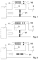
- Fig. 1 is an exhaust main line at the exhaust outlet of an internal combustion engine 1 2 connected.
- a bypass line 3 branches from the main line 2 from, in which an exhaust gas-heated heat exchanger 4 is arranged.
- Valve V1 arranged in the form of a throttle valve.
- a second valve V2 downstream in the bypass line 3 attached.
- both valves V1 and V2 are closed. This matches with the first phase, in which the highest back pressure at the exhaust outlet the internal combustion engine 1 is generated.
- 2 shows the position of the valves V1 and V2 in the second phase, in which the first valve V1 is closed and the second valve V2 is opened is.
- Fig. 3 the normal phase or third phase is shown in which the exhaust gas heating is switched off, in particular by opening the first valve V1 is.
- the second valve V2 is preferably closed.
- the exhaust gas flow can flow through the main line 2 unhindered.
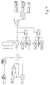
- Fig. 4 the logic of the valve control is dependent on the selected one Phases F shown.
- a subsequent hysteresis for switching limits between phases F should prevent the valves from switching back and forth.
- a coolant temperature-dependent pre-selection then takes place Phase instead.
- a driving cycle temperature threshold T_WFZ e.g. 70 ° C
- an exhaust gas heating temperature threshold T_WHZ e.g. 75 ° C
- the state Z1 can be fulfilled, for example, if the current one Coolant temperature T_W the thermostat opening temperature (e.g. 85 ° C).
- State Z2 can accelerate, for example and state Z3 is a quick release of the accelerator pedal.
- the State Z4 is, for example, the start of the internal combustion engine.
- the two valves V1 and V2 in the form of throttle valves are preferred via a digital black-and-white control (open / close) and via vacuum boxes driven.
- the first valve V1 open and the second valve V2 closed his.
- two vacuum sockets (V actuation) take place at different times: First the first valve V1 is opened and then after a time delay the second valve V2 closed.
- first the second valve V2 opened and then after a time delay the first valve V1 getting closed.
- the map K1 is for example, that of the speed N and the pedal angle sensor PWG dependent driving behavior map, through which the torque request for Control of the amount of fuel is specified.
- the driving behavior map K1 is determined, for example, by a correction characteristic that is dependent on the speed N KL modified.
- the correction characteristic is intended KL of the driving behavior map K1 a torque jump due to or switching off the exhaust throttle with constant pedal angle position prevent.
- the correction quantity is applied in a ramp, the length of the ramp depending on the selected phase F is adjustable.
- the map K2 is, for example, the basic map for an exhaust gas recirculation rate depending on the speed N of the internal combustion engine and the driver's request for torque M_EWUN.
- This basic map K2 is modified via a correction map KK to reflect the changed thermodynamic Conditions with increased exhaust gas back pressure wear.
- the correction target air volume is applied in a ramp depending on the selected phase F.
- About the modified Maps K1 and K2 should always be based on the maximum selection from the coolant temperature dependent and the operating point dependent Preselecting a phase gives the opportunity to change the exhaust backpressures with modified request injection quantities and modified React exhaust gas recirculation rates.
Landscapes
- Engineering & Computer Science (AREA)
- Chemical & Material Sciences (AREA)
- Combustion & Propulsion (AREA)
- Mechanical Engineering (AREA)
- Physics & Mathematics (AREA)
- Thermal Sciences (AREA)
- General Engineering & Computer Science (AREA)
- Exhaust Silencers (AREA)
- Control Of Throttle Valves Provided In The Intake System Or In The Exhaust System (AREA)
Description
- Fig. 1 bis 3
- die Stellungen der Ventile in den drei Phasen und
- Fig. 4
- eine mögliche Steuerlogik der erfindungsgemäßen Abgasheizung.
Claims (6)
- Verfahren zum Betrieb eines Wärmetauschers im Abgasstrom einer Brennkraftmaschine für Kraftfahrzeuge, bei dem der Abgasstrom in eine Hauptleitung (2) und in eine Bypaßleitung (3) aufteilbar ist, bei dem der Wärmetauscher (4) in der Bypaßleitung (3) angeordnet ist und bei dem in einem Warmlaufbetrieb ein Rückstau in der Hauptleitung (2) erzeugbar ist, der einen Gegendruck am Abgasauslaß der Brennkraftmaschine (1) verursacht, wobei der Warmlaufbetrieb in zwei Phasen aufgeteilt wird, wobei in der ersten Phase (F=1) ein höherer Gegendruck als in der zweiten Phase (F=2) erzeugt wird,
dadurch gekennzeichnet, daß ein erstes Ventil (V1) in der Hauptleitung (2) zwischen den Bypaßleitungsanschlüssen und ein zweites Ventil (V2) in der Bypaßleitung (3) stromabwärts vom Wärmetauscher (4) angeordnet sind und daß in der ersten Phase (F=1) beide Ventile (V1, V2) geschlossen sind und in der zweiten Phase (F=2) das erste Ventil (V1) geschlossen, aber das zweite Ventil (V2) geöffnet ist. - Verfahren nach Patentanspruch 1, dadurch gekennzeichnet, daß eine dritte Phase (F=3) als Normalphase definiert ist, bei der vorzugsweise das erste Ventil (V1) geöffnet, aber das zweite Ventil (V2) geschlossen ist.
- Verfahren nach einem der Patentansprüche 1 bis 2, dadurch gekennzeichnet, daß eine Phase (z.B. F=2) in Abhängigkeit von der Kühlmitteltemperatur (T_W) vorausgewählt wird und unabhängig davon eine Phase (z.B. F=1) in Abhängigkeit vom drehmomentbezogenen (M) und/oder drehzahlbezogenen (N) Betriebspunkt der Brennkraftmaschine vorausgewählt wird und daß anschließend bei Ungleichheit der vorausgewählten Phasen die in ihrer Bezifferung höchste Phase (hier: F=2) eingestellt wird.
- Verfahren nach Patentanspruch 2 oder 3, dadurch gekennzeichnet, daß abhängig von vorgegebenen Einzelbetriebszuständen (Z1 bis Z5) vorrangig die dritte Phase (F=3) eingestellt wird.
- Verfahren nach einem der Patentansprüche 1 bis 4, dadurch gekennzeichnet, daß die Ventile (V1, V2) zeitlich versetzt angesteuert werden, wenn die Stellungen beider Ventile (V1, V2) beim Übergang von einer Phase (z.B. F=2) in eine andere Phase (z.B. F=3) geändert werden müssen.
- Verfahren nach einem der Patentansprüche 1 bis 5, dadurch gekennzeichnet, daß die für Brennkraftmaschinen üblicherweise verwendeten Kennfelder (K1, K2) zur Steuerung des Luft-/ Kraftstoffverhältnisses abhängig von der eingestellten Phase modifizierbar sind.
Applications Claiming Priority (2)
| Application Number | Priority Date | Filing Date | Title |
|---|---|---|---|
| DE19725674A DE19725674A1 (de) | 1997-06-18 | 1997-06-18 | Verfahren zum Betrieb eines Wärmetauschers im Abgasstrom einer Brennkraftmaschine für Kraftfahrzeuge |
| DE19725674 | 1997-06-18 |
Publications (3)
| Publication Number | Publication Date |
|---|---|
| EP0885758A2 EP0885758A2 (de) | 1998-12-23 |
| EP0885758A3 EP0885758A3 (de) | 2001-03-21 |
| EP0885758B1 true EP0885758B1 (de) | 2003-07-23 |
Family
ID=7832788
Family Applications (1)
| Application Number | Title | Priority Date | Filing Date |
|---|---|---|---|
| EP98108696A Expired - Lifetime EP0885758B1 (de) | 1997-06-18 | 1998-05-13 | Verfahren zum Betrieb eines Wärmetauschers im Abgasstrom einer Brennkraftmaschine für Kraftfahrzeuge |
Country Status (3)
| Country | Link |
|---|---|
| EP (1) | EP0885758B1 (de) |
| DE (2) | DE19725674A1 (de) |
| ES (1) | ES2205312T3 (de) |
Cited By (2)
| Publication number | Priority date | Publication date | Assignee | Title |
|---|---|---|---|---|
| DE102009013943A1 (de) | 2009-03-19 | 2010-09-23 | Frank Will | Ölschmiersystem |
| EP1512851B2 (de) † | 2003-09-05 | 2014-04-02 | Arvin Technologies, Inc. | Verfahren zur Ventilsteuerung eines Abgassystems |
Families Citing this family (6)
| Publication number | Priority date | Publication date | Assignee | Title |
|---|---|---|---|---|
| DE10017435A1 (de) * | 2000-04-07 | 2001-10-11 | Bayerische Motoren Werke Ag | Abgasanlage einer Brennkraftmaschine,insbesondere für Fahrzeuge |
| GB0121981D0 (en) * | 2001-09-11 | 2001-10-31 | Arvin Internat Uk Ltd | A heat exchanger, an exhaust assembly and a method of mounting the heat exchanger in an exhaust assembly |
| US20090049832A1 (en) | 2005-02-23 | 2009-02-26 | Shuichi Hase | Exhaust heat recovery device |
| EP2631454A1 (de) * | 2012-02-27 | 2013-08-28 | Caterpillar Motoren GmbH & Co. KG | Drosselventil für Verbrennungsmotoren |
| DE102016013705A1 (de) | 2016-11-17 | 2018-05-17 | Daimler Ag | Abgaskühlvorrichtung für eine Verbrennungskraftmaschine |
| US20190255913A1 (en) * | 2018-02-19 | 2019-08-22 | Ford Global Technologies, Llc | System and method for heating a cabin of a motor vehicle |
Family Cites Families (5)
| Publication number | Priority date | Publication date | Assignee | Title |
|---|---|---|---|---|
| DE19500472C2 (de) * | 1995-01-10 | 2003-10-16 | Schatz Thermo Gastech Gmbh | Verfahren zur Reduzierung der Abgasemissionen eines Verbrennungsmotors für Kraftfahrzeuge mit Abgaskatalysator |
| DE19500474A1 (de) * | 1995-01-10 | 1996-07-11 | Schatz Thermo Gastech Gmbh | Verfahren zur Steuerung und Nutzung des Wärmeinhalts der Abgase von Verbrennungsmotoren, insbesondere der Kolbenbauart |
| DE19500476A1 (de) * | 1995-01-10 | 1996-07-11 | Schatz Thermo Gastech Gmbh | Verfahren zur Heizung eines aus einem Verbrennungsmotor und einer von diesem angetriebenen Maschine bestehenden Systems |
| DE19500473A1 (de) | 1995-01-10 | 1996-07-11 | Schatz Thermo Gastech Gmbh | Verfahren zum Betrieb eines Abgaswärmetauschers im Abgasstrom eines Verbrennungsmotors für Kraftfahrzeuge |
| GB2301177A (en) * | 1995-05-18 | 1996-11-27 | Mechadyne Ltd | Exhaust gas heat exchanger in an internal combustion engine |
-
1997
- 1997-06-18 DE DE19725674A patent/DE19725674A1/de not_active Withdrawn
-
1998
- 1998-05-13 EP EP98108696A patent/EP0885758B1/de not_active Expired - Lifetime
- 1998-05-13 DE DE59809062T patent/DE59809062D1/de not_active Expired - Lifetime
- 1998-05-13 ES ES98108696T patent/ES2205312T3/es not_active Expired - Lifetime
Cited By (2)
| Publication number | Priority date | Publication date | Assignee | Title |
|---|---|---|---|---|
| EP1512851B2 (de) † | 2003-09-05 | 2014-04-02 | Arvin Technologies, Inc. | Verfahren zur Ventilsteuerung eines Abgassystems |
| DE102009013943A1 (de) | 2009-03-19 | 2010-09-23 | Frank Will | Ölschmiersystem |
Also Published As
| Publication number | Publication date |
|---|---|
| DE59809062D1 (de) | 2003-08-28 |
| EP0885758A2 (de) | 1998-12-23 |
| ES2205312T3 (es) | 2004-05-01 |
| EP0885758A3 (de) | 2001-03-21 |
| DE19725674A1 (de) | 1998-12-24 |
Similar Documents
| Publication | Publication Date | Title |
|---|---|---|
| DE19833909B4 (de) | Vorrichtung und Verfahren zur drehmomentgestützten Fahrzeuggeschwindigkeitsregelung | |
| EP0874150B1 (de) | Hochleistungsmotor mit sehr niedriger Schadstoffemission | |
| DE3019608C2 (de) | Vorrichtung zur Steuerung des Luftdurchsatzes bei einer Brennkraftmaschine | |
| DE3020493C2 (de) | Verfahren zum steuern des ansaugluftdurchsatzes bei einem brennkraftmotor | |
| DE69507405T2 (de) | Anti-Schlupf-Regelungssystem | |
| DE19713460B4 (de) | Steuersystem für Automatikgetriebe | |
| DE69905485T2 (de) | Verfahren zur steuerung des motordrehmoments während eines schaltvorganges | |
| DE3617051C2 (de) | ||
| DE10014629A1 (de) | System und Verfahren zur Ermittlung des Motordrehmoments zur Steuerung/Regelung des Antriebstrangs eines Kraftfahrzeugs | |
| DE10224063A1 (de) | Verfahren zur Wärmeregulierung einer Brennkraftmaschine für Fahrzeuge | |
| DE19927950A1 (de) | Steuervorrichtung für einen Motor mit elektrisch bzw. elektronisch angetriebenen Einlaß- und Auslaßventilen | |
| DE19512783A1 (de) | Vorrichtung zur Beeinflussung der Getriebeöltemperatur in Kraftfahrzeugen | |
| EP0888921B1 (de) | Steuerung für den Antriebsstrang eines Kraftfahrzeugs | |
| WO1992009448A1 (de) | Verfahren zum betreiben einer aus brennkraftmaschine und automatischem getriebe bestehenden antriebseinheit | |
| DE4343353A1 (de) | Verfahren und Vorrichtung zum Steuern einer Brennkraftmaschine | |
| DE10130633B4 (de) | Verfahren zur Regenerierung eines Partikelfilters | |
| EP0885758B1 (de) | Verfahren zum Betrieb eines Wärmetauschers im Abgasstrom einer Brennkraftmaschine für Kraftfahrzeuge | |
| DE10157714A1 (de) | Verfahren und Vorrichtungen zur Durchführung des Verfahrens zum Beeinflussen der Betriebstemperatur eines hydraulischen Betriebsmittels für ein Antriebsaggregat eines Fahrzeuges | |
| DE10328786B4 (de) | Verfahren zum Betreiben eines Kraftfahrzeuges | |
| DE102017108914A1 (de) | Fahrzeug | |
| DE4037248A1 (de) | Fahrgeschwindigkeits-regelvorrichtung fuer ein kraftfahrzeug | |
| EP1005609A1 (de) | Verfahren zur steuerung der abgasrückführung bei einer brennkraftmaschine | |
| DE19608216B4 (de) | Schaltsteuersystem für ein Automatikgetriebe | |
| DE69304303T2 (de) | Verfahren und einrichtung zur fahrzeuggeschwindigkeitsregelung | |
| DE4392959B4 (de) | Verfahren und Vorrichtung zur Beschleunigung der Erwärmung des Fahrzeugmotors in einem mit einem Retarder ausgestatteten Fahrzeug |
Legal Events
| Date | Code | Title | Description |
|---|---|---|---|
| PUAI | Public reference made under article 153(3) epc to a published international application that has entered the european phase |
Free format text: ORIGINAL CODE: 0009012 |
|
| AK | Designated contracting states |
Kind code of ref document: A2 Designated state(s): DE ES FR GB IT SE |
|
| AX | Request for extension of the european patent |
Free format text: AL;LT;LV;MK;RO;SI |
|
| PUAL | Search report despatched |
Free format text: ORIGINAL CODE: 0009013 |
|
| AK | Designated contracting states |
Kind code of ref document: A3 Designated state(s): AT BE CH CY DE DK ES FI FR GB GR IE IT LI LU MC NL PT SE |
|
| AX | Request for extension of the european patent |
Free format text: AL;LT;LV;MK;RO;SI |
|
| RIC1 | Information provided on ipc code assigned before grant |
Free format text: 7B 60H 1/18 A, 7F 02D 9/00 B, 7F 02D 9/04 B |
|
| 17P | Request for examination filed |
Effective date: 20010912 |
|
| AKX | Designation fees paid |
Free format text: DE ES FR GB IT SE |
|
| 17Q | First examination report despatched |
Effective date: 20020801 |
|
| GRAH | Despatch of communication of intention to grant a patent |
Free format text: ORIGINAL CODE: EPIDOS IGRA |
|
| GRAH | Despatch of communication of intention to grant a patent |
Free format text: ORIGINAL CODE: EPIDOS IGRA |
|
| GRAA | (expected) grant |
Free format text: ORIGINAL CODE: 0009210 |
|
| AK | Designated contracting states |
Designated state(s): DE ES FR GB IT SE |
|
| REG | Reference to a national code |
Ref country code: GB Ref legal event code: FG4D Free format text: NOT ENGLISH |
|
| GBT | Gb: translation of ep patent filed (gb section 77(6)(a)/1977) |
Effective date: 20030723 |
|
| REF | Corresponds to: |
Ref document number: 59809062 Country of ref document: DE Date of ref document: 20030828 Kind code of ref document: P |
|
| REG | Reference to a national code |
Ref country code: SE Ref legal event code: TRGR |
|
| ET | Fr: translation filed | ||
| REG | Reference to a national code |
Ref country code: ES Ref legal event code: FG2A Ref document number: 2205312 Country of ref document: ES Kind code of ref document: T3 |
|
| PLBE | No opposition filed within time limit |
Free format text: ORIGINAL CODE: 0009261 |
|
| STAA | Information on the status of an ep patent application or granted ep patent |
Free format text: STATUS: NO OPPOSITION FILED WITHIN TIME LIMIT |
|
| 26N | No opposition filed |
Effective date: 20040426 |
|
| PGFP | Annual fee paid to national office [announced via postgrant information from national office to epo] |
Ref country code: ES Payment date: 20070430 Year of fee payment: 10 |
|
| PGFP | Annual fee paid to national office [announced via postgrant information from national office to epo] |
Ref country code: SE Payment date: 20070508 Year of fee payment: 10 |
|
| PGFP | Annual fee paid to national office [announced via postgrant information from national office to epo] |
Ref country code: GB Payment date: 20070531 Year of fee payment: 10 |
|
| PGFP | Annual fee paid to national office [announced via postgrant information from national office to epo] |
Ref country code: IT Payment date: 20070524 Year of fee payment: 10 |
|
| PGFP | Annual fee paid to national office [announced via postgrant information from national office to epo] |
Ref country code: FR Payment date: 20070529 Year of fee payment: 10 |
|
| GBPC | Gb: european patent ceased through non-payment of renewal fee |
Effective date: 20080513 |
|
| REG | Reference to a national code |
Ref country code: FR Ref legal event code: ST Effective date: 20090119 |
|
| PG25 | Lapsed in a contracting state [announced via postgrant information from national office to epo] |
Ref country code: FR Free format text: LAPSE BECAUSE OF NON-PAYMENT OF DUE FEES Effective date: 20080602 |
|
| PG25 | Lapsed in a contracting state [announced via postgrant information from national office to epo] |
Ref country code: GB Free format text: LAPSE BECAUSE OF NON-PAYMENT OF DUE FEES Effective date: 20080513 |
|
| REG | Reference to a national code |
Ref country code: ES Ref legal event code: FD2A Effective date: 20080514 |
|
| PG25 | Lapsed in a contracting state [announced via postgrant information from national office to epo] |
Ref country code: IT Free format text: LAPSE BECAUSE OF NON-PAYMENT OF DUE FEES Effective date: 20080513 |
|
| PG25 | Lapsed in a contracting state [announced via postgrant information from national office to epo] |
Ref country code: ES Free format text: LAPSE BECAUSE OF NON-PAYMENT OF DUE FEES Effective date: 20080514 |
|
| PG25 | Lapsed in a contracting state [announced via postgrant information from national office to epo] |
Ref country code: SE Free format text: LAPSE BECAUSE OF NON-PAYMENT OF DUE FEES Effective date: 20080514 |
|
| PGFP | Annual fee paid to national office [announced via postgrant information from national office to epo] |
Ref country code: DE Payment date: 20140614 Year of fee payment: 17 |
|
| REG | Reference to a national code |
Ref country code: DE Ref legal event code: R119 Ref document number: 59809062 Country of ref document: DE |
|
| PG25 | Lapsed in a contracting state [announced via postgrant information from national office to epo] |
Ref country code: DE Free format text: LAPSE BECAUSE OF NON-PAYMENT OF DUE FEES Effective date: 20151201 |