EP0885652B1 - High intensity mixer - Google Patents
High intensity mixer Download PDFInfo
- Publication number
- EP0885652B1 EP0885652B1 EP98201664A EP98201664A EP0885652B1 EP 0885652 B1 EP0885652 B1 EP 0885652B1 EP 98201664 A EP98201664 A EP 98201664A EP 98201664 A EP98201664 A EP 98201664A EP 0885652 B1 EP0885652 B1 EP 0885652B1
- Authority
- EP
- European Patent Office
- Prior art keywords
- mixing
- lid
- vessel
- mixing vessel
- product
- Prior art date
- Legal status (The legal status is an assumption and is not a legal conclusion. Google has not performed a legal analysis and makes no representation as to the accuracy of the status listed.)
- Expired - Lifetime
Links
- 238000002156 mixing Methods 0.000 claims description 63
- 238000001816 cooling Methods 0.000 claims description 7
- 238000010438 heat treatment Methods 0.000 claims description 6
- 239000007788 liquid Substances 0.000 claims description 4
- 230000005540 biological transmission Effects 0.000 claims description 3
- 239000000463 material Substances 0.000 claims description 3
- 238000001035 drying Methods 0.000 claims description 2
- 235000011837 pasties Nutrition 0.000 claims description 2
- 238000010008 shearing Methods 0.000 claims description 2
- 239000000725 suspension Substances 0.000 claims 1
- 238000010586 diagram Methods 0.000 description 2
- 210000000988 bone and bone Anatomy 0.000 description 1
- 239000002639 bone cement Substances 0.000 description 1
- 238000004140 cleaning Methods 0.000 description 1
- 230000001419 dependent effect Effects 0.000 description 1
- 239000012530 fluid Substances 0.000 description 1
- 239000011521 glass Substances 0.000 description 1
- 239000008187 granular material Substances 0.000 description 1
- 239000011796 hollow space material Substances 0.000 description 1
- 238000007689 inspection Methods 0.000 description 1
- 238000000034 method Methods 0.000 description 1
- 239000000843 powder Substances 0.000 description 1
- 239000007921 spray Substances 0.000 description 1
- 238000005507 spraying Methods 0.000 description 1
- 239000000126 substance Substances 0.000 description 1
- 238000003466 welding Methods 0.000 description 1
Images

Classifications
-
- B—PERFORMING OPERATIONS; TRANSPORTING
- B01—PHYSICAL OR CHEMICAL PROCESSES OR APPARATUS IN GENERAL
- B01F—MIXING, e.g. DISSOLVING, EMULSIFYING OR DISPERSING
- B01F33/00—Other mixers; Mixing plants; Combinations of mixers
- B01F33/50—Movable or transportable mixing devices or plants
-
- B—PERFORMING OPERATIONS; TRANSPORTING
- B01—PHYSICAL OR CHEMICAL PROCESSES OR APPARATUS IN GENERAL
- B01F—MIXING, e.g. DISSOLVING, EMULSIFYING OR DISPERSING
- B01F2101/00—Mixing characterised by the nature of the mixed materials or by the application field
- B01F2101/20—Mixing of ingredients for bone cement
-
- B—PERFORMING OPERATIONS; TRANSPORTING
- B01—PHYSICAL OR CHEMICAL PROCESSES OR APPARATUS IN GENERAL
- B01F—MIXING, e.g. DISSOLVING, EMULSIFYING OR DISPERSING
- B01F2101/00—Mixing characterised by the nature of the mixed materials or by the application field
- B01F2101/23—Mixing of laboratory samples e.g. in preparation of analysing or testing properties of materials
-
- B—PERFORMING OPERATIONS; TRANSPORTING
- B01—PHYSICAL OR CHEMICAL PROCESSES OR APPARATUS IN GENERAL
- B01F—MIXING, e.g. DISSOLVING, EMULSIFYING OR DISPERSING
- B01F33/00—Other mixers; Mixing plants; Combinations of mixers
- B01F33/50—Movable or transportable mixing devices or plants
- B01F33/501—Movable mixing devices, i.e. readily shifted or displaced from one place to another, e.g. portable during use
- B01F33/5011—Movable mixing devices, i.e. readily shifted or displaced from one place to another, e.g. portable during use portable during use, e.g. hand-held
Definitions
- the invention relates to a device for mixing, cooling, heating, drying and/or granulating of powder and/or granular materials, comprising a conical mixing vessel having a vertical axis, which narrows in a downward direction and in which at least one vertical mixing shaft can rotate, which mixing shaft a number of element projects, of which the outer end extends until close to the sidewall of the vessel.
- the mixer comprises an agigator having a number of blades, which mixer is connectable to the feed device and a vacuum source which is connectable to the feed device for mixing substances in said feed device under
- the object of the invention is the further development of this mixing device to an intensive mixer for industrial use, with which powdery, granular and/or pasty materials can be mixed, cooled, heated, dried and/or granulated.
- Fig. 1 shows in partial left side view and partial right cross section a mounted mixing device according to a first embodiment with knives that carry paddles at the outer end.
- Fig. 1A shows on an enlarged scale in side and front view details of Fig. 1 of the fastening of the paddles to the rods.
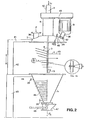
- Fig. 2 shows in partial left side view without outer wall and partial right side view a mixing device according to a second main embodiment, of which the lid has been removed and has been hoisted upwardly over at least the length of the mixing shaft, so that the mixing shaft, the mixing elements and the bottom scraper have become free from the mixing vessel and are visible.
- Fig. 2A shows on an enlarged scale in side view a detail of Fig. 2 of the pivotable connection of the knives to the mixing shaft.
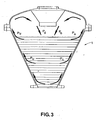
- Fig. 3 shows a diagram of the flow of the product in the intensive mixer according to the invention.
- the mixer is provided with a connical mixing vessel, that is generally indicated with 1, having a vertical axis 2, said vessel narrowing in a downward direction and in which at least one vertical mixing shaft 3 can rotate. From this mixing shaft 3 a number of knives 4 project gradually outwards, of which the outer end 5 extends until near the inner sidewall 6 of the vessel 1.
- the vessel 1 is closed at the upper side with a lid 7, of which the innerside is substantially elipsoide shape, on the one hand for the strength and on the other hand for the inward guiding of the product part Pu that possibly moves upwardly along the inner sidewall 6 into the lid 7 and in the direction of the centre of the lid, from which it again drops back as Pd downwardly in the mixing vessel 1.
- Fig. 3 shows this flow diagram.
- a drive motor 9 is fastened with the use of (not shown) seals and bearings on the central lid tube stub.
- the (not shown) outgoing driveshaft 10 is coupled with the mixing shaft 3.
- the mixing vessel 1 with the hoistable lid 7 can be closed vacuum tight by means of different types of quick fasteners, such as the screwbolt having a starhead 11 and the clamping screw 12, so that during the operation vacuum can be applied to the mixing vessel 1.
- quick fasteners such as the screwbolt having a starhead 11 and the clamping screw 12, so that during the operation vacuum can be applied to the mixing vessel 1.
- hoist means such as the arm 41, the double acting plunger 42, the cylinder 43 and the second arm 44 in Fig. 2.
- the mixing knives 4 can be cleaned, exchanged or repaired. It is also possible to inspect the vessel 1 internally or the lid 7 can be removed and quickly exchanged with an other lid with accessories.
- a scraper blade 13 is fastened in order to obviate a dead space in the bottom of the mixing vessel 1.
- An excentric tube stub 14 is also mounted on the lid 7, which stub can be opened and closed by means of an inspection lid 15. This is done with a pivotable arm 16, which can be screwed with a starhead 17 on a screwbolt 18 in the closing position in a uppertaining sidelog 19 of the stub 14.
- a flange 23 is fastened, on which the body is mounted of a ball segment valve 24, which contains a ball segment 25.
- the mixing vessel 1 is provided with an outer jacket 26 for heating and for cooling of the contents of a product P of the vessel 1.
- This jacket 26 carries the connecting tube stumps 28 and 29.
- the sidewall 6 is made of a so-called “template”, which is a double walled plate 13 that has been connected by welding in different places and is afterwards expended. Through the created hollow space again a cooling or heating medium can be circulated.
- the lid 7 comprises a tube stub 32 for a looking glass 33.
- the mixing shaft 3 carries a great number of knives 4 and has a high to very high number of revolutions N.
- the product to be treated experiences a very strong shearing at both the knives 4 as the inner sidewall 6, so that in a very short time a very intensive mixing of the product P is effected.
- a temperature rise can occur, which is counteracted by cooling the sidewall 6 of the mixing vessel 1.
- the number of revolutions N of the mixing vessel comprises 100 tot 1000 revolutions per minute.
- the knives 4 each carry at the outer end one or more mixing paddles 5, of which an outer edge extends parallel to and near the inner sidewall 6 of the vessel 1. Furthermore, the knives 4 are rod shaped and have a large radial dimension. Furthermore, the paddles 5 are plate shaped and have a small radial dimension. According to Fig. 1A at the left side of Fig. 1 the paddles 5 are limited pivotable over an angle (A) round the longitudinal axis of the rod shaped element.
- a second preferential embodiment of the invention is shown in the hoisted position of the lid 7 with accessories.
- the lid 7 is suspended on the upwardly and downwardly moveable horizontal arm 41 on the head of a hydraulic plunger 42 of a hoisting cylinder 43 which carries a fixed horizontal arm 44 at the upperside, on which the mixing vessel 1 is suspended. Also other that hydraulic hoisting tools can be applied.
- the knives 4 according to the invention comprise knives, of which the angle B with the vertical of at least a part of the knives is variable.
- FIG. 2A At a variant drawn at the right side of Fig. 2 the mixing shaft 3 and the knives 4 that are connected therewith are hollow and have outlet holes 45 for letting through and guiding of gasses and/or liquids U.
- Fig. 2A also a detail of the pivotable connection of the knives 4 with the mixing shaft 3 is shown. Here the scraper 13 at the lower end of the mixing shaft 3 is visible.
- the angle B is variable which the knives 4 make with the vertical.
- the outer sidewall 6 of the mixing vessel 1 is bound with a 1/2 tube spiral 46 for passing through a cooling and/or heating fluid.
- the lid 7 is provided with a tube stub 36 for the entrance of the product Pi.
- a flat outlet slide 47 with an operating lever 48 for the outgoing product PO is mounted.
- the mixing shaft 3 is accoupled by means of a transmission 49 with the inverted suspended drive motor 9, which transmission is fastened on the lid 7 by means of a heightened tube stub 8.
- a heightened tube stub 8 In the axis 2 an inlet 50 for liquid Li is mounted.
- the lid 7 is also provided with a port 38 for a low pressure sprayer 39 for process liquid and/or gas.
- the sidewall 6 of the mixing vessel 1 is provided at the right side with a port 34 for a thermometer 35.
Landscapes
- Chemical & Material Sciences (AREA)
- Chemical Kinetics & Catalysis (AREA)
- Mixers Of The Rotary Stirring Type (AREA)
- Accessories For Mixers (AREA)
- Crushing And Pulverization Processes (AREA)
Description
- The invention relates to a device for mixing, cooling, heating, drying and/or granulating of powder and/or granular materials, comprising a conical mixing vessel having a vertical axis, which narrows in a downward direction and in which at least one vertical mixing shaft can rotate, which mixing shaft a number of element projects, of which the outer end extends until close to the sidewall of the vessel.
- From US-4,721,390 a medical mixer of very small dimensions is known for preparing under vacuum bone cement for fixing protheses at surrounding bone tissue.
- The mixer comprises an agigator having a number of blades, which mixer is connectable to the feed device and a vacuum source which is connectable to the feed device for mixing substances in said feed device under
- The object of the invention is the further development of this mixing device to an intensive mixer for industrial use, with which powdery, granular and/or pasty materials can be mixed, cooled, heated, dried and/or granulated.
- According to the invention this object is reached with a device according to independent claim 1. Further details of the invention are defined in the dependent claims.
- Other characteristics and advantages of the invention will resort from the description below of a number of embodiments, referring to the accompanying drawing.
- Fig. 1 shows in partial left side view and partial right cross section a mounted mixing device according to a first embodiment with knives that carry paddles at the outer end.
- Fig. 1A shows on an enlarged scale in side and front view details of Fig. 1 of the fastening of the paddles to the rods.
- Fig. 2 shows in partial left side view without outer wall and partial right side view a mixing device according to a second main embodiment, of which the lid has been removed and has been hoisted upwardly over at least the length of the mixing shaft, so that the mixing shaft, the mixing elements and the bottom scraper have become free from the mixing vessel and are visible.
- Fig. 2A shows on an enlarged scale in side view a detail of Fig. 2 of the pivotable connection of the knives to the mixing shaft.
- Fig. 3 shows a diagram of the flow of the product in the intensive mixer according to the invention.
- According to Fig. 1 the mixer is provided with a connical mixing vessel, that is generally indicated with 1, having a
vertical axis 2, said vessel narrowing in a downward direction and in which at least onevertical mixing shaft 3 can rotate. From this mixing shaft 3 a number ofknives 4 project gradually outwards, of which theouter end 5 extends until near theinner sidewall 6 of the vessel 1. - The vessel 1 is closed at the upper side with a
lid 7, of which the innerside is substantially elipsoide shape, on the one hand for the strength and on the other hand for the inward guiding of the product part Pu that possibly moves upwardly along theinner sidewall 6 into thelid 7 and in the direction of the centre of the lid, from which it again drops back as Pd downwardly in the mixing vessel 1. Fig. 3 shows this flow diagram. - On top of the
lid 7 in theaxis 2 of the central mixing shaft 3 adrive motor 9 is fastened with the use of (not shown) seals and bearings on the central lid tube stub. Of thisdrive motor 9 the (not shown)outgoing driveshaft 10 is coupled with themixing shaft 3. The mixing vessel 1 with thehoistable lid 7 can be closed vacuum tight by means of different types of quick fasteners, such as the screwbolt having astarhead 11 and theclamping screw 12, so that during the operation vacuum can be applied to the mixing vessel 1. After the loosening of the quick acting fasteners it is possible to hoist thelid 2 together with its accessories by means of hoist means, such as thearm 41, thedouble acting plunger 42, thecylinder 43 and thesecond arm 44 in Fig. 2. In this way themixing knives 4 can be cleaned, exchanged or repaired. It is also possible to inspect the vessel 1 internally or thelid 7 can be removed and quickly exchanged with an other lid with accessories. At the lower end of the mixing screw 3 ascraper blade 13 is fastened in order to obviate a dead space in the bottom of the mixing vessel 1. - An
excentric tube stub 14 is also mounted on thelid 7, which stub can be opened and closed by means of aninspection lid 15. This is done with apivotable arm 16, which can be screwed with astarhead 17 on ascrewbolt 18 in the closing position in auppertaining sidelog 19 of thestub 14. On thelid 7 there is also apassage 20 for acleaning sprayer device 21 that can be extended and retracted, which spraying device carries aspray head 22 inside the vessel 1. At the lower side of the mixing vessel 1 aflange 23 is fastened, on which the body is mounted of aball segment valve 24, which contains aball segment 25. - At the left half of Fig. 1 is shown, that the mixing vessel 1 is provided with an
outer jacket 26 for heating and for cooling of the contents of a product P of the vessel 1. Thisjacket 26 carries the connectingtube stumps - It is also possible, such as shown in the right half of Fig. 1, that the
sidewall 6 is made of a so-called "template", which is a doublewalled plate 13 that has been connected by welding in different places and is afterwards expended. Through the created hollow space again a cooling or heating medium can be circulated. Thelid 7 comprises atube stub 32 for a lookingglass 33. - According to the invention the
mixing shaft 3 carries a great number ofknives 4 and has a high to very high number of revolutions N. In this way the product to be treated experiences a very strong shearing at both theknives 4 as theinner sidewall 6, so that in a very short time a very intensive mixing of the product P is effected. By this mixing action a temperature rise can occur, which is counteracted by cooling thesidewall 6 of the mixing vessel 1. - According to a main embodiment of the invention the number of revolutions N of the mixing vessel comprises 100 tot 1000 revolutions per minute.
- At a first preferential embodiment of the invention the
knives 4 each carry at the outer end one ormore mixing paddles 5, of which an outer edge extends parallel to and near theinner sidewall 6 of the vessel 1. Furthermore, theknives 4 are rod shaped and have a large radial dimension. Furthermore, thepaddles 5 are plate shaped and have a small radial dimension. According to Fig. 1A at the left side of Fig. 1 thepaddles 5 are limited pivotable over an angle (A) round the longitudinal axis of the rod shaped element. - In Fig. 2 a second preferential embodiment of the invention is shown in the hoisted position of the
lid 7 with accessories. Thelid 7 is suspended on the upwardly and downwardly moveablehorizontal arm 41 on the head of ahydraulic plunger 42 of a hoistingcylinder 43 which carries a fixedhorizontal arm 44 at the upperside, on which the mixing vessel 1 is suspended. Also other that hydraulic hoisting tools can be applied. - Here the
knives 4 according to the invention comprise knives, of which the angle B with the vertical of at least a part of the knives is variable. - At a variant drawn at the right side of Fig. 2 the
mixing shaft 3 and theknives 4 that are connected therewith are hollow and haveoutlet holes 45 for letting through and guiding of gasses and/or liquids U. In Fig. 2A also a detail of the pivotable connection of theknives 4 with themixing shaft 3 is shown. Here thescraper 13 at the lower end of themixing shaft 3 is visible. - At the variant shown at the left side of Fig. 2 the angle B is variable which the
knives 4 make with the vertical. Furthermore, theouter sidewall 6 of the mixing vessel 1 is bound with a 1/2tube spiral 46 for passing through a cooling and/or heating fluid. Thelid 7 is provided with atube stub 36 for the entrance of the product Pi. At the lower end of the mixing vessel 1 aflat outlet slide 47 with anoperating lever 48 for the outgoing product PO is mounted. - At the upperside of the mixing vessel 1 the
mixing shaft 3 is accoupled by means of atransmission 49 with the inverted suspendeddrive motor 9, which transmission is fastened on thelid 7 by means of a heightenedtube stub 8. In theaxis 2 aninlet 50 for liquid Li is mounted. Thelid 7 is also provided with aport 38 for alow pressure sprayer 39 for process liquid and/or gas. - The
sidewall 6 of the mixing vessel 1 is provided at the right side with aport 34 for athermometer 35.
Claims (15)
- Device for batch mixing, cooling, heating, drying and/or granulating powdery, granular and/or pasty materials (P), comprising a conical mixing vessel (1) having a vertical axis (2), which vessel narrows in a downward direction and in which at least one vertical mixing shaft (3) can rotate, of which mixing shaft (3) multiple knives project radially, of which the outer end extends until the vicinity of the side wall (6) of the vessel (1), characterized in that it comprises knives (4) carrying one ore more mixing paddles (5) at the outer end and the mixing shaft (3) has a number of revolutions (N) that amounts to 100 to 1000 revolutions per minute, so that the centrifugal force in combination with the rotation moves the product (P) with a movement upward along the sloping side wall, after which it falls downward along the vertical axis (2) of the vessel (1) during which the material to be treated is experiencing a shearing at both the paddles (5) and at the inner wall (6), the one and the other such, that an intensive mixing of the product (P) is effected.
- Device according to claim 1, characterised in that, the knives (4) are rod shaped and have a large radial dimension, whereas the paddles (5) are plate shaped and have a small radial dimension, and are limited pivotable over an angle (A) around the longitudinal axis of the rod shaped knive (4), of which paddles a radial outerwall extends parallel to and near to the inner sidewall (6) of the vessel (1).
- Device according to one or more of claims 1 and 2, characterised in that, a scraper blade (11) is mounted at the lower end of the mixing shaft (3) for obviating dead space in the bottom of the mixing vessel (1).
- Device according to one or more of claims 1 through 3, in which the mixing vessel (1) is closed by a lid (7) at the upperside, characterised in that, the innerside of the lid (7) on the mixing vessel (1) is substantially elipsoide shaped, for guiding the part of the product (Pu) moving upward along the inner sidewall (6) from the sidewall (6) in the direction of the centre of the lid (7), from which it drops down again into the mixing vessel (1) as the product part (Pd).
- Device according to one or more of claims 1 through 4, characterised in that, the lid (7) with accessories can close the mixing vessel (1) airtight, so that vacuum can be applied on the mixing vessel (1).
- Device according to one or more of claims 1 through 5, characterised in that, the lid (7) is fastened by means of quick acting fasteners (11, 12) on the mixing vessel (1), so that after loosening the quick acting fasteners (11, 12) the lid (7) with accessories can be hoisted from the mixing vessel (1) and can be replaced and fastened again after treatment and/or replacement.
- Device according to one or more of claims 1 through 6, characterised in that, the mixing vessel (1) is provided with an outer jacket (26) for heating and/or cooling of the contents of product (P) of the vessel (1), whereas to this end the connecting tube stubs (28, 29) are present.
- Device according to one or more of claims 1 through 7, characterised in that, at the lower end of the mixing vessel (1) a ball segment valve (24) is mounted.
- Device according to one or more of claims 1 through 8, characterised in that, at the lower end of the mixing vessel (1) a flat outlet slide valve (47, 48) is mounted.
- Device according to one or more of claims 1 through 9, characterised in that, the mixing shaft (3) is coupled by means of a transmission (49) with an invertedly suspended drivemotor (9), in which on the lid (7) a raised tube stub (8) is fastened, which carries the suspension (49) on which the motor (9) is invertedly suspended.
- Device according to one or more of claims 1 through 10, characterised in that the sidewall (6) of the mixing vessel (1) is provided with a port (34) for a thermometer (35).
- Device according to one or more of claims 1 through 11, characterised in that, the lid (7) is provided with a tub stub (36) for the entry of product (P).
- Device according to one or more of claims 1 through 12, characterised in that, the lid (7) is provided with a port (40) for a liquid sprayer (39).
- Device according to one or more of claims 1 trough 13, characterised in that the lid (7) is suspended to the upwardly and downwardly moveable horizontal arm (41) at the head of a plunger (42) of a hydraulic hoisting cylinder (43) which carries a fixed horizontal arm (44) at the upper side, on which the mixing vessel (1) is suspended.
- Device according to one or more of claims 1 through 14, characterised in that, the lid (7) is suspended to the upwardly and downwardly moveable arm (41) of a mechanical hoisting device.
Applications Claiming Priority (2)
| Application Number | Priority Date | Filing Date | Title |
|---|---|---|---|
| NL1006311 | 1997-06-13 | ||
| NL1006311A NL1006311C2 (en) | 1997-06-13 | 1997-06-13 | Intensive mixer. |
Publications (2)
| Publication Number | Publication Date |
|---|---|
| EP0885652A1 EP0885652A1 (en) | 1998-12-23 |
| EP0885652B1 true EP0885652B1 (en) | 2007-03-21 |
Family
ID=19765161
Family Applications (1)
| Application Number | Title | Priority Date | Filing Date |
|---|---|---|---|
| EP98201664A Expired - Lifetime EP0885652B1 (en) | 1997-06-13 | 1998-05-19 | High intensity mixer |
Country Status (4)
| Country | Link |
|---|---|
| EP (1) | EP0885652B1 (en) |
| JP (1) | JP4211015B2 (en) |
| DE (1) | DE69837365T2 (en) |
| NL (1) | NL1006311C2 (en) |
Cited By (1)
| Publication number | Priority date | Publication date | Assignee | Title |
|---|---|---|---|---|
| CN110813460A (en) * | 2019-12-02 | 2020-02-21 | 苏州塔比诺机电有限公司 | A raw material grinding device for the production of electronic components |
Families Citing this family (8)
| Publication number | Priority date | Publication date | Assignee | Title |
|---|---|---|---|---|
| US6599005B2 (en) * | 1997-06-13 | 2003-07-29 | Hosokawa Micron Bv | Intensive mixer |
| JP2002181224A (en) * | 2000-12-14 | 2002-06-26 | Mitsui Mining Co Ltd | Discharge valve |
| JP2008513205A (en) * | 2004-09-21 | 2008-05-01 | グラクソ グループ リミテッド | Mixing system and method |
| CN103041747A (en) * | 2011-10-15 | 2013-04-17 | 四川制药制剂有限公司 | Low power dissipation quick stirring granulator convenient to observe the reaction situation |
| DE102013018094A1 (en) * | 2013-12-03 | 2015-06-03 | Merck Patent Gmbh | Mixing device and its use |
| CN107282234A (en) * | 2017-07-17 | 2017-10-24 | 邹铁梅 | A kind of Feed Manufacturing is with being pulverized and mixed integration apparatus |
| CN108187840A (en) * | 2017-12-28 | 2018-06-22 | 吴烨程 | A kind of multidirectional crushing filter feed device of at the uniform velocity intermittent feeding |
| CN115090211B (en) * | 2022-06-08 | 2023-09-22 | 苏州思萃热控材料科技有限公司 | An integrated drying and granulating equipment for the preparation of aluminum silicon carbide composite materials |
Family Cites Families (5)
| Publication number | Priority date | Publication date | Assignee | Title |
|---|---|---|---|---|
| IT1169505B (en) * | 1983-02-24 | 1987-06-03 | Luciano Occelli | PROCESS AND APPARATUS FOR VACUUM MIXING OF MIXTURES FOR DENTAL, GOLDsmith OR SIMILAR USE |
| SE450545B (en) * | 1984-10-19 | 1987-07-06 | Mit Ab | PROCEDURE AND DEVICE FOR MANUFACTURING BENCEMENT FOR FIXING PROSTHESIS |
| ATE61469T1 (en) * | 1987-09-10 | 1991-03-15 | Hosokawa Micron Europ | DEVICE FOR DRYING SOLVENT CONTAINING MATERIAL. |
| US5265956A (en) * | 1991-09-30 | 1993-11-30 | Stryker Corporation | Bone cement mixing and loading apparatus |
| US5505538A (en) * | 1993-07-06 | 1996-04-09 | Earle; Michael L. | Automated bone cement mixing apparatus |
-
1997
- 1997-06-13 NL NL1006311A patent/NL1006311C2/en not_active IP Right Cessation
-
1998
- 1998-05-19 EP EP98201664A patent/EP0885652B1/en not_active Expired - Lifetime
- 1998-05-19 DE DE69837365T patent/DE69837365T2/en not_active Expired - Lifetime
- 1998-06-01 JP JP15083898A patent/JP4211015B2/en not_active Expired - Lifetime
Cited By (1)
| Publication number | Priority date | Publication date | Assignee | Title |
|---|---|---|---|---|
| CN110813460A (en) * | 2019-12-02 | 2020-02-21 | 苏州塔比诺机电有限公司 | A raw material grinding device for the production of electronic components |
Also Published As
| Publication number | Publication date |
|---|---|
| EP0885652A1 (en) | 1998-12-23 |
| JPH1147573A (en) | 1999-02-23 |
| DE69837365T2 (en) | 2007-12-13 |
| DE69837365D1 (en) | 2007-05-03 |
| NL1006311C2 (en) | 1998-12-15 |
| JP4211015B2 (en) | 2009-01-21 |
Similar Documents
| Publication | Publication Date | Title |
|---|---|---|
| US6599005B2 (en) | Intensive mixer | |
| US4199266A (en) | Processing vessels | |
| EP0885652B1 (en) | High intensity mixer | |
| ES2284609T3 (en) | DEVICE FOR THE HANDLING OF SUBSTANCES. | |
| KR100787397B1 (en) | Agitator | |
| JP2003126669A (en) | Arrangement structure of stirrer and scraper and kettle device provided with the same | |
| JP2003117373A (en) | Kettle apparatus | |
| HU210406B (en) | Fluid processor apparatus | |
| KR100357739B1 (en) | Batch mixer | |
| AU717390B2 (en) | Food processing vat | |
| CN218130193U (en) | Sterile flat filter washing and drying machine | |
| GB2116059A (en) | A rotary mixing apparatus | |
| JP2003144889A (en) | Mixer | |
| US4632025A (en) | Steam peeling apparatus | |
| CN219128957U (en) | Mixing arrangement is used in production of silicone adhesive | |
| KR20170006173A (en) | System for reducing weight of organized sludge by fermentation and dry | |
| ES2935366T3 (en) | Device for the manufacture of granules or extruded products | |
| JP2003144896A (en) | Drainage device and kettle device | |
| CN109012350A (en) | A kind of powdery paints blender with cleaning device | |
| GB2194460A (en) | Agitator assembly for a rotary mixing apparatus | |
| CN218359257U (en) | Mixing reaction kettle | |
| CN209027260U (en) | A kind of efficient conisphere type auger drying machine | |
| CN212091906U (en) | A refractory material mixer | |
| CN222093329U (en) | Reation kettle is used in cutting fluid production | |
| CN213493688U (en) | A reation kettle for high-efficient haloxyfop original medicine |
Legal Events
| Date | Code | Title | Description |
|---|---|---|---|
| PUAI | Public reference made under article 153(3) epc to a published international application that has entered the european phase |
Free format text: ORIGINAL CODE: 0009012 |
|
| 17P | Request for examination filed |
Effective date: 19981009 |
|
| AK | Designated contracting states |
Kind code of ref document: A1 Designated state(s): CH DE FR GB LI NL SE |
|
| AX | Request for extension of the european patent |
Free format text: AL;LT;LV;MK;RO;SI |
|
| AKX | Designation fees paid | ||
| RBV | Designated contracting states (corrected) |
Designated state(s): CH DE FR GB LI NL SE |
|
| 17Q | First examination report despatched |
Effective date: 20020508 |
|
| GRAP | Despatch of communication of intention to grant a patent |
Free format text: ORIGINAL CODE: EPIDOSNIGR1 |
|
| GRAS | Grant fee paid |
Free format text: ORIGINAL CODE: EPIDOSNIGR3 |
|
| GRAA | (expected) grant |
Free format text: ORIGINAL CODE: 0009210 |
|
| AK | Designated contracting states |
Kind code of ref document: B1 Designated state(s): CH DE FR GB LI NL SE |
|
| REG | Reference to a national code |
Ref country code: GB Ref legal event code: FG4D |
|
| REG | Reference to a national code |
Ref country code: CH Ref legal event code: EP |
|
| REF | Corresponds to: |
Ref document number: 69837365 Country of ref document: DE Date of ref document: 20070503 Kind code of ref document: P |
|
| REG | Reference to a national code |
Ref country code: SE Ref legal event code: TRGR |
|
| REG | Reference to a national code |
Ref country code: CH Ref legal event code: NV Representative=s name: SPIERENBURG & PARTNER AG, PATENT- UND MARKENANWAEL |
|
| ET | Fr: translation filed | ||
| PLBE | No opposition filed within time limit |
Free format text: ORIGINAL CODE: 0009261 |
|
| STAA | Information on the status of an ep patent application or granted ep patent |
Free format text: STATUS: NO OPPOSITION FILED WITHIN TIME LIMIT |
|
| 26N | No opposition filed |
Effective date: 20071227 |
|
| REG | Reference to a national code |
Ref country code: DE Ref legal event code: R082 Ref document number: 69837365 Country of ref document: DE Representative=s name: PATENTANWAELTE UND RECHTSANWALT WEISS, ARAT & , DE Ref country code: DE Ref legal event code: R082 Ref document number: 69837365 Country of ref document: DE Representative=s name: PATENTANWAELTE UND RECHTSANWALT DR. WEISS, ARA, DE |
|
| REG | Reference to a national code |
Ref country code: FR Ref legal event code: PLFP Year of fee payment: 19 |
|
| PGFP | Annual fee paid to national office [announced via postgrant information from national office to epo] |
Ref country code: NL Payment date: 20160504 Year of fee payment: 19 |
|
| PGFP | Annual fee paid to national office [announced via postgrant information from national office to epo] |
Ref country code: DE Payment date: 20160506 Year of fee payment: 19 Ref country code: GB Payment date: 20160506 Year of fee payment: 19 Ref country code: CH Payment date: 20160609 Year of fee payment: 19 |
|
| PGFP | Annual fee paid to national office [announced via postgrant information from national office to epo] |
Ref country code: SE Payment date: 20160506 Year of fee payment: 19 Ref country code: FR Payment date: 20160513 Year of fee payment: 19 |
|
| REG | Reference to a national code |
Ref country code: DE Ref legal event code: R119 Ref document number: 69837365 Country of ref document: DE |
|
| REG | Reference to a national code |
Ref country code: CH Ref legal event code: PL |
|
| REG | Reference to a national code |
Ref country code: SE Ref legal event code: EUG |
|
| REG | Reference to a national code |
Ref country code: NL Ref legal event code: MM Effective date: 20170601 |
|
| GBPC | Gb: european patent ceased through non-payment of renewal fee |
Effective date: 20170519 |
|
| PG25 | Lapsed in a contracting state [announced via postgrant information from national office to epo] |
Ref country code: SE Free format text: LAPSE BECAUSE OF NON-PAYMENT OF DUE FEES Effective date: 20170520 Ref country code: CH Free format text: LAPSE BECAUSE OF NON-PAYMENT OF DUE FEES Effective date: 20170531 Ref country code: LI Free format text: LAPSE BECAUSE OF NON-PAYMENT OF DUE FEES Effective date: 20170531 |
|
| REG | Reference to a national code |
Ref country code: FR Ref legal event code: ST Effective date: 20180131 |
|
| PG25 | Lapsed in a contracting state [announced via postgrant information from national office to epo] |
Ref country code: NL Free format text: LAPSE BECAUSE OF NON-PAYMENT OF DUE FEES Effective date: 20170601 |
|
| PG25 | Lapsed in a contracting state [announced via postgrant information from national office to epo] |
Ref country code: GB Free format text: LAPSE BECAUSE OF NON-PAYMENT OF DUE FEES Effective date: 20170519 Ref country code: DE Free format text: LAPSE BECAUSE OF NON-PAYMENT OF DUE FEES Effective date: 20171201 |
|
| PG25 | Lapsed in a contracting state [announced via postgrant information from national office to epo] |
Ref country code: FR Free format text: LAPSE BECAUSE OF NON-PAYMENT OF DUE FEES Effective date: 20170531 |