EP0885633A2 - Method and apparatus for fire prevention - Google Patents
Method and apparatus for fire prevention Download PDFInfo
- Publication number
- EP0885633A2 EP0885633A2 EP98110477A EP98110477A EP0885633A2 EP 0885633 A2 EP0885633 A2 EP 0885633A2 EP 98110477 A EP98110477 A EP 98110477A EP 98110477 A EP98110477 A EP 98110477A EP 0885633 A2 EP0885633 A2 EP 0885633A2
- Authority
- EP
- European Patent Office
- Prior art keywords
- spark
- conveying
- fire
- flow
- detected
- Prior art date
- Legal status (The legal status is an assumption and is not a legal conclusion. Google has not performed a legal analysis and makes no representation as to the accuracy of the status listed.)
- Granted
Links
Images

Classifications
-
- A—HUMAN NECESSITIES
- A62—LIFE-SAVING; FIRE-FIGHTING
- A62C—FIRE-FIGHTING
- A62C3/00—Fire prevention, containment or extinguishing specially adapted for particular objects or places
- A62C3/06—Fire prevention, containment or extinguishing specially adapted for particular objects or places of highly inflammable material, e.g. light metals, petroleum products
Definitions
- the invention relates to a method and an apparatus for Fire prevention according to the preamble of claim 1 or of claim 4.
- sparks can cause fires and explosions come.
- the flying of sparks is usually used by a Processing machine or due to material contamination generated. Production downtimes, high property damage or even danger of human lives are the result.
- the invention is based on the object, method and device of the type mentioned at the outset, that in a simple and inexpensive manner, safe fire prevention can be guaranteed.
- An essential idea of the present invention lies in the fact that there is continuous funding a point is interrupted so that the flow in Individual quantities are divided, which in turn is fire-safe promoted separately. After that, the Funding is continuous again. Because of this Unraveling is now possible, even with little effort, such as it brings a quick-closing slide with it, the promotion to stop by simply holding the single amount becomes. This can be done particularly easily using a rotary valve happen as it is known per se.
- the gas becomes pneumatic, ie by means of gas (especially air) preferably before dividing the bulk material into individual quantities separated from the bulk material, for example by means of a cyclone happens.
- gas especially air
- the preferred rotary valve is as usual equipped with a drive motor that controls the conveying speed the cellular wheel sluice is determined. Usually passes a period of about 0.5 to 1 s from the inlet of one Quantity of product in a cell until it continues to rotate until the product can exit the cell. In in most cases it will therefore suffice to add the cell drive Detect a spark to safely shut off to reach.
- a brake is preferably provided, as it is known in principle for geared motors anyway. Such brakes work so that when the motor is energized the brake opens and when the power is turned off, the brake closes automatically (e.g. by spring force) and the drive fixes, which then a particularly quick stopping the Cellular wheel movement is ensured.
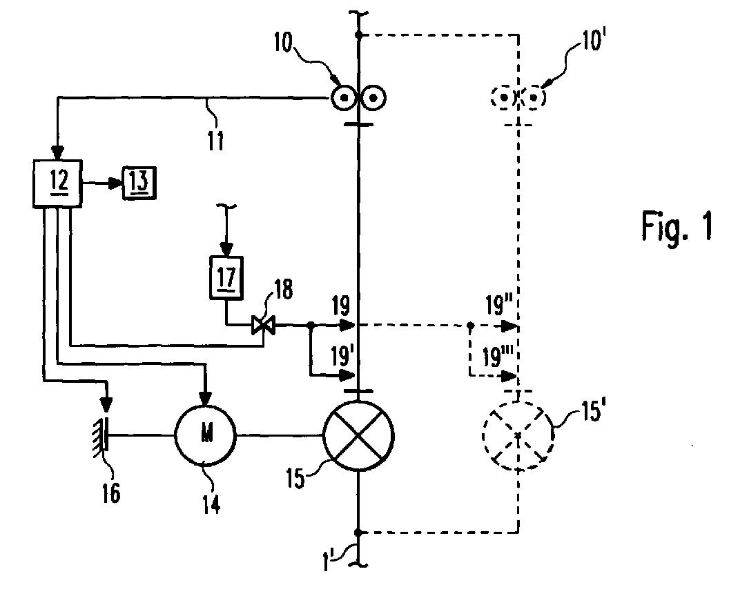
- a spark detector 10 which the Heat radiation monitored in the pipeline 1.
- a spark detector 10 As soon as an abnormally hot zone that represents a possible source of fire, flows past the spark detector (in the arrangement according to Fig. 1 "falls by"), a corresponding signal via a Signal line 11 transmitted to a central controller 12. The latter then not only inputs a warning device 13 Warning signal, but provides the power supply to a motor 14 from which drives a rotary valve 15. Furthermore, a Brake 16 engaged, which thus the rotation of the electric motor 14 accelerates breaks.
- the source of the fire can start be deleted and / or removed.
- To delete is with the 1 arrangement shown under pressure Extinguishing agent (water) storage 17 provided via a valve 18 is connected to spray devices 19, 19 'which in the pipe section 1 in which the source of the fire is located, and, if appropriate, in one, the pipeline section 1 Inject the extinguishing agent into the facing cell of the rotary valve 15.
- the overall arrangement is designed such that the cellular wheel sluice 15 and between the spark detector 10 and the Pipe wheel lock lying pipe section can be easily cleared can to the product contaminated with extinguishing agent remove.
- the pipe section between the spark detector 10 and the rotary valve 15 together Content can be removed from the entire pipeline.
- the rotary valve 15 accordingly these requirements Easy removability of contaminated Cell contents
- a bypass arrangement is provided in broken lines, which in turn has a spark detector 10 ', extinguishing nozzles 19' ', 19 '' 'and a rotary valve 15' includes, so that after detection a source of fire by the spark detector 10 and stopping the rotary valve 15 the product flow on the bypass arrangement can be redirected while using extinguishing agent contaminated product removed. This means less downtime ensured.
- FIG. 2 differs differs from that of FIG. 1 in that in the pipeline 1 subsidized product pneumatic and not outdoors Case (as in the arrangement of FIG. 1) is transported.
- a cyclone 20 is provided which separates the gas from the solid.
- the separated gas runs through a further pipeline 21 to one Filter 22, which separates any entrained dusts.
- a slide 22 is provided, which is also controlled by the controller 12, namely on a spark detection signal from the spark detector 10 such as this has already been explained above.
- the slider 22 provided in the arrangement according to FIG. 2 must Now don't be too fast, because the distance, which one possible source of fire (sparks) covered by the cyclone 20 is extended considerably. This means (similar to the rotary valve 15) has a longer reaction time or a slower operation of the slide 22 permitted without the operational safety to endanger. Also in the arrangement according to Fig. 2, however, the solids flow through the rotary valve 15 interrupted.
- Fig. 1 The variants shown in Fig. 1 are of course in the arrangement 2 also applicable. In particular, this would be the reasonably easy access to the inside of the cyclone 20 (or its content), the provision of extinguishing devices (not shown separately in Fig. 2) or the interchangeability of pipe sections or cells in the rotary valve 15.
Landscapes
- Chemical & Material Sciences (AREA)
- Engineering & Computer Science (AREA)
- Chemical Kinetics & Catalysis (AREA)
- General Chemical & Material Sciences (AREA)
- Oil, Petroleum & Natural Gas (AREA)
- Health & Medical Sciences (AREA)
- Public Health (AREA)
- Business, Economics & Management (AREA)
- Emergency Management (AREA)
- Fire-Extinguishing By Fire Departments, And Fire-Extinguishing Equipment And Control Thereof (AREA)
- Diaphragms For Electromechanical Transducers (AREA)
- Safety Valves (AREA)
- Fire-Detection Mechanisms (AREA)
- Air Transport Of Granular Materials (AREA)
- Control Of Conveyors (AREA)
Abstract
Zur Brandverhinderung, insbesondere zum Ausscheiden und Löschen
von Funken beim Fördern feuergefährdeter Schüttgüter in Fördereinrichtungen,
insbesondere in Rohrleitungen, ist es bekannt,
daß man beim Erkennen einer Zone mit überhöhter Temperatur,
insbesondere eines Funkens in einem Förderstrom durch eine Funkenerkennungseinrichtung
den Förderstrom an einem zweiten,
stromab der Funkenerkennungseinrichtung gelegenen Ort unterbrechen
und den Funken bzw. Brandherd eliminieren oder löschen
kann. Zum Unterbrechen werden aufwendige Schieber verwendet,
die sehr schnell arbeiten müssen.
Es wird vorgeschlagen, den Förderstrom in im wesentlichen kontinuierlich
bewegte Einzelmengen zu unterteilen, die über einen
Wegabschnitt feuersicher voneinander getrennt gefördert und
beim Erkennen eines Funkens angehalten werden.
It is proposed to subdivide the flow into essentially continuously moving individual quantities, which are conveyed separately from one another over a distance in a fire-safe manner and are stopped when a spark is detected.
Description
Die Erfindung betrifft ein Verfahren sowie eine Vorrichtung zur Brandverhinderung nach dem Oberbegriff des Patentanspruches 1 bzw. des Patentanspruches 4.The invention relates to a method and an apparatus for Fire prevention according to the preamble of claim 1 or of claim 4.
In pneumatischen Transporteinrichtungen und mechanischen Förderanlagen, in denen brennbare Schüttgüter transportiert werden, kann es durch Funkenflug zu Bränden und Explosionen kommen. Der Funkenflug wird in der Regel durch eine eingesetzte Verarbeitungsmaschine oder aber durch Materialverunreinigungen erzeugt. Produktionsausfälle, hoher Sachschaden oder gar Gefährdung von Menschenleben sind die Folge.In pneumatic transport devices and mechanical conveyor systems, in which flammable bulk goods are transported, sparks can cause fires and explosions come. The flying of sparks is usually used by a Processing machine or due to material contamination generated. Production downtimes, high property damage or even danger of human lives are the result.
Um dieses Risiko auszuschließen, ist es bekannt, die pneumatischen und mechanischen Fördereinrichtungen auf Funkenflug hin zu überwachen und durch Funkenlöschanlagen zu sichern. Hierbei wird über Funkenmelder Infrarotstrahlung festgestellt, wobei die Empfindlichkeit der bekannten Einrichtungen inzwischen so hoch ist, daß eine sichere Funkenerkennung bei einer geeigneten Anordnung in jedem Fall gewährleistet sein kann.To rule out this risk, it is known to use pneumatic and mechanical conveyors on flying sparks to be monitored and secured with spark extinguishing systems. Here is detected via spark detectors, infrared radiation, whereby the sensitivity of the known devices meanwhile It is high that reliable spark detection with a suitable one Arrangement can be guaranteed in any case.
Weiterhin wird bei den bekannten Funkenlöschanlagen nach Erkennung eines Funkens eine Löscheinrichtung betätigt, die - stromab des Funkenmelders - ein Löschmittel, insbesondere einen Wassernebel an einer geeigneten Stelle einspritzt. Der den Löschvorhang passierende Funke wird dabei abgelöscht. Dies kann jedoch nur dann gemacht werden, wenn das überwachte Produkt durch den Löschvorgang nicht zerstört wird. Wenn es sich beispielsweise um Getreidemehl handelt, also eine Förderanlage in einer Getreidemühle überwacht wird, wären die Folgen eines solchen Löschvorgangs katastrophal. In einem solchen Fall muß mit einem sogenannten Schnellschieber gearbeitet werden, also einem Verschlußorgan, das hinreichend schnell die Förderanlage absperrt, bevor das Löschmittel eingesprüht wird. Die zeitliche Steuerung bzw. räumliche Anordnung muß also bestimmten Bedingungen genügen, die eine Kontaminierung des nicht-zurückgehaltenen Fördergutes und damit der nachfolgenden Anlageneinrichtungen verhindern.Furthermore, in the known spark extinguishing systems after detection of a spark actuates an extinguishing device which - downstream of the spark detector - an extinguishing agent, in particular injects a water mist at a suitable location. Of the Spark passing through the fire curtain is extinguished. This however, can only be done if the monitored product is not destroyed by the deletion process. If it is for example, grain flour, i.e. a conveyor system would be monitored in a grain mill, the consequences would be one such deletion catastrophic. In such a case be worked with a so-called quick pusher, so a locking device that the conveyor system sufficiently quickly shuts off before the extinguishing agent is sprayed. The temporal Control or spatial arrangement must therefore certain conditions suffice a contamination of the non-retained Goods to be conveyed and thus the subsequent plant facilities prevent.
Besonders problematisch an dieser bekannten Anordnung bzw. Verfahrensweise ist die Tatsache, daß derartige Schnellschlußschieber ausgesprochen teuer sind. Die Arbeitsgeschwindigkeit ist dennoch beschränkt, so daß bei hohen Fördergeschwindigkeiten relativ lange Strecken zwischen dem Funkenmelder und Schnellschlußschieber und dementsprechend auch große mit Löschmittel kontaminierte Fördermengen in Kauf zu nehmen sind. Diese wiederum müssen nach einem Funken-Löschvorgang entsorgt werden, was in verschiedener Hinsicht problematisch ist.Particularly problematic with this known arrangement or procedure is the fact that such quick closing slides are extremely expensive. The working speed is nevertheless limited, so that at high conveyor speeds relatively long distances between the spark detector and Quick closing slide and accordingly also large ones Extinguishing media contaminated flow rates must be accepted. These in turn must be disposed of after a spark extinguishing process become what is problematic in various ways.
Der Erfindung liegt die Aufgabe zugrunde, Verfahren und Vorrichtung der eingangs genannten Art dahingehend weiterzubilden, daß in einfacher und kostengünstiger Weise eine sichere Brandverhinderung gewährleistet werden kann.The invention is based on the object, method and device of the type mentioned at the outset, that in a simple and inexpensive manner, safe fire prevention can be guaranteed.
Diese Aufgabe wird verfahrensmäßig durch die im Anspruch 1 und vorrichtungsmäßig durch die im Anspruch 4 angegebenen Merkmale gelöst.This task is procedurally by the in claim 1 and device-wise by the features specified in claim 4 solved.
Ein wesentlicher Gedanke der vorliegenden Erfindung liegt darin, daß eine an sich kontinuierlich erfolgende Förderung an einer Stelle unterbrochen wird, so daß der Förderstrom in Einzelmengen unterteilt wird, die wiederum feuersicher voneinander getrennt gefördert werden. Danach kann die Förderung wieder kontinuierlich erfolgen. Durch dieses Auftrennen wird es nun möglich, auch ohne großen Aufwand, wie ihn ein Schnellschlußschieber mit sich bringt, die Förderung anzuhalten, indem die Einzelmenge ganz einfach festgehalten wird. Dies kann besonders einfach durch eine Zellenradschleuse geschehen, wie sie an sich bekannt ist.An essential idea of the present invention lies in the fact that there is continuous funding a point is interrupted so that the flow in Individual quantities are divided, which in turn is fire-safe promoted separately. After that, the Funding is continuous again. Because of this Unraveling is now possible, even with little effort, such as it brings a quick-closing slide with it, the promotion to stop by simply holding the single amount becomes. This can be done particularly easily using a rotary valve happen as it is known per se.
Wenn das Produkt nicht im freien Fall gefördert wird, sondern pneumatisch, also mittels Gas (insbesondere Luft) wird das Gas vorzugsweise vor dem Unterteilen des Schüttguts in Einzelmengen vom Schüttgut abgetrennt, was beispielsweise mittels eines Zyklons geschieht. Die Leitung, mit welcher die Luft vom Zyklon zu einem Filter geführt wird, muß zwar auch abgesperrt werden, jedoch ist die für einen Funken zurückzulegende Flugstrecke durch seine im Zyklon zurückzulegende Strecke erheblich verlängert, so daß die Arbeitsgeschwindigkeit des Schiebers nicht allzu hoch sein muß, was ihn wiederum einfacher, zuverlässiger und kostengünstiger macht.If the product is not promoted in free fall, but instead The gas becomes pneumatic, ie by means of gas (especially air) preferably before dividing the bulk material into individual quantities separated from the bulk material, for example by means of a cyclone happens. The line with which the air from the cyclone is led to a filter, must also be shut off, however, is the flight distance to be covered for a spark considerably extended due to its distance to be covered in the cyclone, so the working speed of the slider is not must be too high, which in turn makes it easier, more reliable and makes it cheaper.
Die vorzugsweise verwendete Zellenradschleuse ist wie üblich mit einem Antriebsmotor ausgestattet, der die Fördergeschwindigkeit der Zellenradschleuse bestimmt. Üblicherweise vergeht hierbei eine Zeitdauer von etwa 0,5 bis 1 s vom Einlaß einer Produktmenge in eine Zelle, bis diese soweit weitergedreht wurde, bis das Produkt wieder aus der Zelle austreten kann. In den meisten Fällen wird es somit genügen, den Zellenantrieb bei Erkennung eines Funkens abzustellen, um die Absperrung sicher zu erreichen. Vorzugsweise wird jedoch eine Bremse vorgesehen, wie sie bei Getriebemotoren ohnehin im Prinzip bekannt ist. Derartige Bremsen arbeiten so, daß bei Bestromung des Motors die Bremse öffnet und bei Abstellen der Stromzufuhr die Bremse selbsttätig (z. B. durch Federkraft) schließt und den Antrieb festsetzt, wodurch dann ein besonders schnelles Abstoppen der Zellenradbewegung sichergestellt ist.The preferred rotary valve is as usual equipped with a drive motor that controls the conveying speed the cellular wheel sluice is determined. Usually passes a period of about 0.5 to 1 s from the inlet of one Quantity of product in a cell until it continues to rotate until the product can exit the cell. In in most cases it will therefore suffice to add the cell drive Detect a spark to safely shut off to reach. However, a brake is preferably provided, as it is known in principle for geared motors anyway. Such brakes work so that when the motor is energized the brake opens and when the power is turned off, the brake closes automatically (e.g. by spring force) and the drive fixes, which then a particularly quick stopping the Cellular wheel movement is ensured.
Bevorzugte Ausführungsformen der Erfindung ergeben sich aus den Unteransprüchen.Preferred embodiments of the invention result from the Subclaims.
Nachfolgend wird die Erfindung anhand von Ausführungsbeispielen erläutert, zu deren Beschreibung die beiliegenden Abbildungen dienen. The invention is described below using exemplary embodiments explained, for the description of which the enclosed figures to serve.
Hierbei zeigen:
- Fig. 1
- eine schematische Darstellung einer ersten Ausführungsform der Erfindung und
- Fig. 2
- eine zweite Ausführungsform der Erfindung in einer Darstellung ähnlich der nach Fig. 1.
- Fig. 1
- is a schematic representation of a first embodiment of the invention and
- Fig. 2
- a second embodiment of the invention in a representation similar to that of FIG. 1st
Bei der nachfolgenden Beschreibung werden für gleiche und gleichwirkende Teile dieselben Bezugsziffern verwendet.In the following description, the same and equivalent parts used the same reference numerals.
Bei der in Fig. 1 gezeigten Ausführungsform der Erfindung ist
in eine Rohrleitung 1, 1' zum Fördern eines brennbaren Materials
wie z. B. Getreidemehl oder chemischer Stoffe, die
ebenso wie Getreidemehl feuchtigkeitsempfindlich sind, in an
sich bekannter Weise ein Funkenmelder 10 vorgesehen, der die
Wärmestrahlung innerhalb der Rohrleitung 1 überwacht. Sobald
eine anormal heiße Zone, die einen möglichen Brandherd darstellt,
am Funkenmelder vorbeiströmt (bei der Anordnung nach
Fig. 1 "vorbeifällt"), wird ein entsprechendes Signal über eine
Signalleitung 11 an eine zentrale Steuerung 12 übermittelt.
Diese gibt daraufhin nicht nur über eine Warneinrichtung 13 ein
Warnsignal ab, sondern stellt die Stromzufuhr zu einem Motor 14
ab, der eine Zellenradschleuse 15 antreibt. Weiterhin wird eine
Bremse 16 eingerückt, die somit die Drehung des Elektromotors
14 beschleunigt unterbricht. Dadurch nun, daß die Zellenradschleuse
15 in der Rohrleitung 1, 1' angebracht ist, wird der
an sich durch die kontinuierliche Bewegung der Zellen in der
Zellenradschleuse 15 im wesentlichen kontinuierliche (wenn auch
in Einzel-Portionen aufgeteilt) erfolgende Produktstrom mit absoluter
Sicherheit zu einem Zeitpunkt unterbrochen, zu welchem
die erkannte (mögliche) Brandzone aus dem vor der Zellenradschleuse
15 liegenden Förderleitungsabschnitt 1 noch nicht in
den nach der Zellenradschleuse 15 liegenden Rohrleitungsabschnitt
1' gelangt ist. Dies ist insbesondere dadurch sichergestellt,
daß die bei Zellenradschleusen übliche "Totzeit", also
die Zeit vom Eintritt eines Produkts in eine Zelle und dessen
Weiterförderung bis zu einem Austrittsbereich im allgemeinen
0,5 bis 1 s beträgt, also relativ lang ist. In jedem Fall ist
diese Zeit lang genug, um den Motor 14 (gegebenenfalls mit der
daran vorgesehenen Bremse 16) abzustoppen. Ein besonderer Aufwand
ist hierzu nicht notwendig.In the embodiment of the invention shown in FIG
into a pipeline 1, 1 'for conveying a combustible material
such as B. cereal flour or chemical substances that
just as corn flour is sensitive to moisture, in
known a
Sobald die Zellenradschleuse 15 angehalten ist, kann der Brandherd
gelöscht und/oder entfernt werden. Zum Löschen ist bei der
in Fig. 1 gezeigten Anordnung ein unter Druck gesetzter
Löschmittel-(Wasser)-Speicher 17 vorgesehen, der über ein Ventil
18 mit Sprüheinrichtungen 19, 19' verbunden ist, welche in
den Rohrleitungsabschnitt 1, in dem sich der Brandherd befindet,
sowie gegebenenfalls in eine, dem Rohrleitungsabschnitt 1
zugewandte Zelle der Zellenradschleuse 15 das Löschmittel einspritzen.As soon as the
Die Gesamtanordnung ist derart ausgebildet, daß die Zellenradschleuse
15 und der zwischen dem Funkenmelder 10 und der
Zellenradschleuse liegende Rohrabschnitt leicht ausgeräumt werden
können, um das mit Löschmittel kontaminierte Produkt zu
entfernen. Bei besonders schwer löschbaren Produkten kann natürlich
auch das Produkt samt Brandherd entfernt werden, um den
Löschvorgang an geeigneter Stelle durchzuführen. Hierzu ist es
insbesondere von Vorteil, wenn der Rohrleitungsabschnitt zwischen
dem Funkenmelder 10 und der Zellenradschleuse 15 samt
Inhalt aus der Gesamt-Rohrleitung heraustrennbar ist. Weiterhin
ist es von Vorteil, wenn die Zellenradschleuse 15 entsprechend
diesen Anforderungen (leichte Entfernbarkeit kontaminierter
Zelleninhalte) entsprechend ausgebildet ist. Hierzu wird
vorgeschlagen, die Zellen der Zellenradschleuse mit
entfernbaren Einsätzen derart zu versehen und öffenbar auszugestalten,
daß man Zellen samt Inhalt leicht auswechseln kann.The overall arrangement is designed such that the
Bei der in Fig. 1 gezeigten Ausführungsform ist (gegebenenfalls
zusätzlich) in unterbrochenen Linien eine Bypass-Anordnung vorgesehen,
die wiederum einen Funkenmelder 10', Löschdüsen 19'',
19''' sowie eine Zellenradschleuse 15' umfaßt, so daß nach Erkennen
eines Brandherdes durch den Funkenmelder 10 und Anhalten
der Zellenradschleuse 15 der Produktstrom auf die Bypass-Anordnung
umgeleitet werden kann, während man das mit Löschmittel
kontaminierte Produkt entfernt. Dadurch ist eine geringere Betriebsunterbrechung
sichergestellt. In the embodiment shown in FIG. 1, (where appropriate
in addition) a bypass arrangement is provided in broken lines,
which in turn has a spark detector 10 ', extinguishing nozzles 19' ',
19 '' 'and a rotary valve 15' includes, so that after detection
a source of fire by the
Die in Fig. 2 gezeigte Ausführungsform der Erfindung unterscheidet
sich von der nach Fig. 1 dadurch, daß das in der Rohrleitung
1 geförderte Produkt pneumatisch und nicht im freien
Fall (wie bei der Anordnung nach Fig. 1) befördert wird. Um das
fördernde Gas abzuscheiden, ist vor der Zellenradschleuse 15
ein Zyklon 20 vorgesehen, der das Gas vom Feststoff trennt. Das
abgetrennte Gas läuft durch eine weitere Rohrleitung 21 zu einem
Filter 22, das gegebenenfalls mitgeführte Stäube abscheidet.
In der Rohrleitung 21 ist ein Schieber 22 vorgesehen, der
ebenfalls von der Steuerung 12 angesteuert wird, und zwar auf
ein Funkenerkennungssignal aus dem Funkenmelder 10, wie dies
schon oben erläutert wurde.The embodiment of the invention shown in FIG. 2 differs
differs from that of FIG. 1 in that in the pipeline
1 subsidized product pneumatic and not outdoors
Case (as in the arrangement of FIG. 1) is transported. To do that
Separating gas to be extracted is in front of the rotary valve 15
a
Der bei der Anordnung nach Fig. 2 vorgesehene Schieber 22 muß
nun nicht allzu schnell sein, da die Wegstrecke, welche ein
möglicher Brandherd (Funken) zurücklegt, durch den Zyklon 20
ganz erheblich verlängert wird. Dadurch ist (ähnlich wie bei
der Zellenradschleuse 15) eine längere Reaktionszeit bzw. eine
langsamere Arbeitsweise des Schiebers 22 zulässig, ohne die Betriebssicherheit
zu gefährden. Auch bei der Anordnung nach Fig.
2 wird jedoch der Feststoff-Fluß durch die Zellenradschleuse 15
unterbrochen.The
Die in Fig. 1 gezeigten Varianten sind natürlich bei der Anordnung
nach Fig. 2 ebenfalls anwendbar. Insbesondere wären dies
die hinreichend einfache Zugänglichkeit des Inneren des Zyklons
20 (bzw. dessen Inhaltes), das Vorsehen von Löscheinrichtungen
(in Fig. 2 nicht gesondert gezeichnet) oder die Austauschbarkeit
von Rohrabschnitten oder Zellen in der Zellenradschleuse
15.The variants shown in Fig. 1 are of course in the arrangement
2 also applicable. In particular, this would be
the reasonably easy access to the inside of the cyclone
20 (or its content), the provision of extinguishing devices
(not shown separately in Fig. 2) or the interchangeability
of pipe sections or cells in the
- 1, 1'1, 1 '
- RohrleitungPipeline
- 1010th
- FunkenmelderSpark detector
- 1111
- SignalleitungSignal line
- 1212th
- SteuerleitungControl line
- 1313
- WarneinrichtungWarning device
- 1414
- Motor engine
- 1515
- ZellenradschleuseCell wheel lock
- 1616
- Bremsebrake
- 1717th
- LöschmittelspeicherExtinguishing agent storage
- 1818th
- VentilValve
- 19, 19'19, 19 '
- Düsejet
- 2020th
- Zykloncyclone
- 2121
- RohrleitungPipeline
- 2222
- SchieberSlider
Claims (10)
dadurch gekennzeichnet, daß
der Förderstrom in im wesentlichen kontinuierlich bewegte Einzelmengen unterteilt wird, die über einen Wegabschnitt feuersicher voneinander getrennt gefördert und beim Erkennen eines Funkens angehalten werden.Method for preventing fire, in particular for eliminating and / or extinguishing sources of fire, in particular sparks when conveying bulk goods at risk of fire in conveying devices, in particular in pipelines, whereby when a zone with increased temperature, in particular sparking in a conveying stream, is detected by a spark detection device, in particular a spark detector at a first location, the flow is interrupted at a second, downstream location and the spark is eliminated,
characterized in that
the flow is divided into essentially continuously moving individual quantities, which are conveyed separately from one another in a fire-safe manner and stopped when a spark is detected.
dadurch gekennzeichnet, daß
beim pneumatischen Fördern mittels Gas, insbesondere Luft, das Gas vor dem Unterteilen des Schüttguts in Einzelmengen vom Schüttgut getrennt wird.Method according to claim 1,
characterized in that
in pneumatic conveying by means of gas, in particular air, the gas is separated from the bulk material in individual quantities before the bulk material is divided.
dadurch gekennzeichnet, daß
bei angehaltenem Förderstrom ein zwischen Funkenerkennung und Unterteilung in Einzelmengen befindliches Fördervolumen gekühlt, insbesondere durch Zuführen von Wasser gekühlt wird.Method according to one of the preceding claims,
characterized in that
when the flow is stopped, a delivery volume located between spark detection and subdivision is cooled, in particular by supplying water.
die Absperreinrichtung (15) eine Fördereinrichtung umfaßt, die derart ausgebildet ist, daß der Förderstrom in im wesentlichen kontinuierlich bewegte Einzelmengen unterteilt wird, die über einen Wegabschnitt feuersicher voneinander getrennt gefördert und beim Erkennen eines Funkens angehalten werden.Device for fire prevention, in particular for eliminating and / or extinguishing sparks when conveying bulk materials at risk of fire in conveying devices, in particular in pipelines (1, 1 ')
the shut-off device (15) comprises a conveying device which is designed in such a way that the conveying flow is subdivided into essentially continuously moving individual quantities which are conveyed separately from one another in a fire-safe manner and are stopped when a spark is detected.
dadurch gekennzeichnet, daß
die Fördereinrichtung eine Zellenradschleuse (15) umfaßt.Device according to claim 4,
characterized in that
the conveying device comprises a cellular wheel sluice (15).
dadurch gekennzeichnet, daß
die Zellenradschleuse (15) einen abbremsbaren Antrieb (14, 16) umfaßt.Device according to claim 5,
characterized in that
the cellular wheel sluice (15) comprises a brakeable drive (14, 16).
dadurch gekennzeichnet, daß
die Fördereinrichtung (15) bei pneumatischer Schüttgutförderung eine Gasabscheideeinrichtung, insbesondere einen Zyklon (20) umfaßt. Device according to claim 4,
characterized in that
the conveying device (15) in the case of pneumatic bulk material conveying comprises a gas separating device, in particular a cyclone (20).
gekennzeichnet durch
eine Kühl-, insbesondere eine Wassereinspritzeinrichtung (17-19), die zwischen dem Funkenmelder (10) und der Absperreinrichtung (15) zum Abkühlen des Funkens bzw. Brandherdes installiert ist.Device according to one of claims 4 to 6,
characterized by
a cooling, in particular a water injection device (17-19), which is installed between the spark detector (10) and the shut-off device (15) for cooling the spark or the source of the fire.
dadurch gekennzeichnet, daß
der Förder-, insbesondere Rohrleitungsbereich zwischen dem Funkenmelder (10) und der Absperreinrichtung (15) zum Inspizieren und/oder Ausräumen seines Inhaltes öffenbar ist.Device according to one of claims 4 to 8,
characterized in that
the conveying area, in particular the pipe area, between the spark detector (10) and the shut-off device (15) can be opened for inspecting and / or clearing its contents.
dadurch gekennzeichnet, daß
der Förder-, insbesondere Rohrleitungsabschnitt austauschbar ausgebildet, vorzugsweise mittels Schiebern oder dergleichen als Container versiegelbar ist.Device according to one of claims 4 to 9,
characterized in that
the conveying section, in particular the pipe section, is designed to be interchangeable, preferably sealed as a container by means of slides or the like.
Applications Claiming Priority (2)
| Application Number | Priority Date | Filing Date | Title |
|---|---|---|---|
| DE19726096A DE19726096C1 (en) | 1997-06-19 | 1997-06-19 | Fire prevention method and apparatus |
| DE19726096 | 1997-06-19 |
Publications (3)
| Publication Number | Publication Date |
|---|---|
| EP0885633A2 true EP0885633A2 (en) | 1998-12-23 |
| EP0885633A3 EP0885633A3 (en) | 2000-11-08 |
| EP0885633B1 EP0885633B1 (en) | 2004-12-29 |
Family
ID=7833050
Family Applications (1)
| Application Number | Title | Priority Date | Filing Date |
|---|---|---|---|
| EP98110477A Expired - Lifetime EP0885633B1 (en) | 1997-06-19 | 1998-06-08 | Method and apparatus for fire prevention |
Country Status (3)
| Country | Link |
|---|---|
| EP (1) | EP0885633B1 (en) |
| AT (1) | ATE285822T1 (en) |
| DE (2) | DE19726096C1 (en) |
Cited By (2)
| Publication number | Priority date | Publication date | Assignee | Title |
|---|---|---|---|---|
| CN109481881A (en) * | 2018-11-21 | 2019-03-19 | 汇乐因斯福环保安全研究院(苏州)有限公司 | Spark detection and extinguishing means and spark detection extinguishing method for dust pipeline |
| EP4596467A1 (en) * | 2024-01-30 | 2025-08-06 | Coperion GmbH | Protective system with a cellular wheel sluice for bulk material |
Families Citing this family (2)
| Publication number | Priority date | Publication date | Assignee | Title |
|---|---|---|---|---|
| DE20218136U1 (en) | 2002-11-21 | 2003-03-06 | Minimax Gmbh, 23843 Bad Oldesloe | Spark extinguishing system for moving dust-like particles |
| DE10321438A1 (en) * | 2003-05-12 | 2004-12-02 | Klaus Buttler | Combustible swarf extraction unit has detectors in cyclone controlling delivery unit to prevent ignition of collected material |
Family Cites Families (3)
| Publication number | Priority date | Publication date | Assignee | Title |
|---|---|---|---|---|
| US4637473A (en) * | 1986-01-16 | 1987-01-20 | Kidde, Inc. | Fire suppression system |
| DE4326072A1 (en) * | 1993-08-04 | 1995-02-09 | Ruhrgas Ag | Device for automatically closing a shut-off valve |
| SE9303305L (en) * | 1993-10-08 | 1994-11-21 | Firefly Ab | Preventive protection system |
-
1997
- 1997-06-19 DE DE19726096A patent/DE19726096C1/en not_active Expired - Fee Related
-
1998
- 1998-06-08 EP EP98110477A patent/EP0885633B1/en not_active Expired - Lifetime
- 1998-06-08 DE DE59812431T patent/DE59812431D1/en not_active Expired - Fee Related
- 1998-06-08 AT AT98110477T patent/ATE285822T1/en not_active IP Right Cessation
Cited By (2)
| Publication number | Priority date | Publication date | Assignee | Title |
|---|---|---|---|---|
| CN109481881A (en) * | 2018-11-21 | 2019-03-19 | 汇乐因斯福环保安全研究院(苏州)有限公司 | Spark detection and extinguishing means and spark detection extinguishing method for dust pipeline |
| EP4596467A1 (en) * | 2024-01-30 | 2025-08-06 | Coperion GmbH | Protective system with a cellular wheel sluice for bulk material |
Also Published As
| Publication number | Publication date |
|---|---|
| DE19726096C1 (en) | 1999-03-04 |
| EP0885633A3 (en) | 2000-11-08 |
| DE59812431D1 (en) | 2005-02-03 |
| EP0885633B1 (en) | 2004-12-29 |
| ATE285822T1 (en) | 2005-01-15 |
Similar Documents
| Publication | Publication Date | Title |
|---|---|---|
| EP2469492B1 (en) | Method and device for fire detection in volumes | |
| DE60207319T2 (en) | Method and apparatus for firefighting in an aircraft compartment equipped with this device | |
| EP0244858B1 (en) | Filter device for a fire-extinguishing installation | |
| DE69419533T2 (en) | DEVICE FOR PREVENTING FIRE CAUSED BY BURNING OR GLOWING PARTICLES IN A PIPELINE | |
| EP0287935B1 (en) | Crushing device for containers | |
| DE19726096C1 (en) | Fire prevention method and apparatus | |
| EP4150140B1 (en) | Spinning facility with a protective device | |
| DE4227220A1 (en) | Dry process to filter incineration or smelting particles from smoke - uses additives, infrared detectors and extinguishing system to reduce fire risk preventing or minimising damage to filters | |
| DE102007014662A1 (en) | Exploitation device driving method for use in underground mine, involves measuring gas concentration, and sending alarm when unqualified mutual relationship occurs between determined exploitation quantity and measured gas concentration | |
| EP1422675B1 (en) | Device for decoupling dust-laden installations with risk of explosion | |
| DE102008061914B4 (en) | Protective device, filter device containing these and method for protecting the filter device against fire hazard | |
| DE3321195A1 (en) | Device for the dry heat sterilisation of glass vessels for medicaments for parenteral use | |
| DE2845980B2 (en) | Method and device for inerting a plant system containing combustible material | |
| DE10321438A1 (en) | Combustible swarf extraction unit has detectors in cyclone controlling delivery unit to prevent ignition of collected material | |
| DE19921485C2 (en) | Method and device for removing chips from light metal | |
| WO1998000201A1 (en) | Process and device for dynamically applying a fire extinguishing agent | |
| DE69419182T2 (en) | DEVICE FOR DETECTING PARTICLES IN A LINE | |
| DE69912246T2 (en) | DEVICE AND METHOD FOR PROCESSING CLINICAL WASTE | |
| DE202011105211U1 (en) | Device with at least one laser processing system and filter system for connection to a laser processing system | |
| WO2005119213A1 (en) | Device and method for optically detecting substances contained in waste gases of chemical processes | |
| DE102019131263B4 (en) | Detection device with water spray extinguishing system | |
| DE8805008U1 (en) | Device for crushing containers | |
| DE102008044709A1 (en) | Method and device for conveying combustion residues | |
| DE2345640A1 (en) | WASTE INCINERATOR | |
| DE102021116273A1 (en) | Extinguishing device and extinguishing method for pneumatic transport lines |
Legal Events
| Date | Code | Title | Description |
|---|---|---|---|
| PUAI | Public reference made under article 153(3) epc to a published international application that has entered the european phase |
Free format text: ORIGINAL CODE: 0009012 |
|
| AK | Designated contracting states |
Kind code of ref document: A2 Designated state(s): AT BE CH DE DK FI FR GB LI LU NL SE |
|
| AX | Request for extension of the european patent |
Free format text: AL;LT;LV;MK;RO;SI |
|
| PUAL | Search report despatched |
Free format text: ORIGINAL CODE: 0009013 |
|
| AK | Designated contracting states |
Kind code of ref document: A3 Designated state(s): AT BE CH CY DE DK ES FI FR GB GR IE IT LI LU MC NL PT SE |
|
| AX | Request for extension of the european patent |
Free format text: AL;LT;LV;MK;RO;SI |
|
| RIC1 | Information provided on ipc code assigned before grant |
Free format text: 7A 62C 3/04 A |
|
| 17P | Request for examination filed |
Effective date: 20010425 |
|
| AKX | Designation fees paid |
Free format text: AT BE CH DE DK FI FR GB LI LU NL SE |
|
| GRAP | Despatch of communication of intention to grant a patent |
Free format text: ORIGINAL CODE: EPIDOSNIGR1 |
|
| GRAS | Grant fee paid |
Free format text: ORIGINAL CODE: EPIDOSNIGR3 |
|
| GRAA | (expected) grant |
Free format text: ORIGINAL CODE: 0009210 |
|
| AK | Designated contracting states |
Kind code of ref document: B1 Designated state(s): AT BE CH DE DK FI FR GB LI LU NL SE |
|
| PG25 | Lapsed in a contracting state [announced via postgrant information from national office to epo] |
Ref country code: NL Free format text: LAPSE BECAUSE OF FAILURE TO SUBMIT A TRANSLATION OF THE DESCRIPTION OR TO PAY THE FEE WITHIN THE PRESCRIBED TIME-LIMIT Effective date: 20041229 Ref country code: GB Free format text: LAPSE BECAUSE OF FAILURE TO SUBMIT A TRANSLATION OF THE DESCRIPTION OR TO PAY THE FEE WITHIN THE PRESCRIBED TIME-LIMIT Effective date: 20041229 Ref country code: FR Free format text: LAPSE BECAUSE OF FAILURE TO SUBMIT A TRANSLATION OF THE DESCRIPTION OR TO PAY THE FEE WITHIN THE PRESCRIBED TIME-LIMIT Effective date: 20041229 Ref country code: FI Free format text: LAPSE BECAUSE OF FAILURE TO SUBMIT A TRANSLATION OF THE DESCRIPTION OR TO PAY THE FEE WITHIN THE PRESCRIBED TIME-LIMIT Effective date: 20041229 |
|
| REG | Reference to a national code |
Ref country code: GB Ref legal event code: FG4D Free format text: NOT ENGLISH |
|
| REG | Reference to a national code |
Ref country code: CH Ref legal event code: EP |
|
| REF | Corresponds to: |
Ref document number: 59812431 Country of ref document: DE Date of ref document: 20050203 Kind code of ref document: P |
|
| PG25 | Lapsed in a contracting state [announced via postgrant information from national office to epo] |
Ref country code: SE Free format text: LAPSE BECAUSE OF FAILURE TO SUBMIT A TRANSLATION OF THE DESCRIPTION OR TO PAY THE FEE WITHIN THE PRESCRIBED TIME-LIMIT Effective date: 20050329 Ref country code: DK Free format text: LAPSE BECAUSE OF FAILURE TO SUBMIT A TRANSLATION OF THE DESCRIPTION OR TO PAY THE FEE WITHIN THE PRESCRIBED TIME-LIMIT Effective date: 20050329 |
|
| NLV1 | Nl: lapsed or annulled due to failure to fulfill the requirements of art. 29p and 29m of the patents act | ||
| PG25 | Lapsed in a contracting state [announced via postgrant information from national office to epo] |
Ref country code: LU Free format text: LAPSE BECAUSE OF NON-PAYMENT OF DUE FEES Effective date: 20050608 Ref country code: AT Free format text: LAPSE BECAUSE OF NON-PAYMENT OF DUE FEES Effective date: 20050608 |
|
| PG25 | Lapsed in a contracting state [announced via postgrant information from national office to epo] |
Ref country code: LI Free format text: LAPSE BECAUSE OF NON-PAYMENT OF DUE FEES Effective date: 20050630 Ref country code: CH Free format text: LAPSE BECAUSE OF NON-PAYMENT OF DUE FEES Effective date: 20050630 Ref country code: BE Free format text: LAPSE BECAUSE OF NON-PAYMENT OF DUE FEES Effective date: 20050630 |
|
| GBV | Gb: ep patent (uk) treated as always having been void in accordance with gb section 77(7)/1977 [no translation filed] |
Effective date: 20041229 |
|
| PLBE | No opposition filed within time limit |
Free format text: ORIGINAL CODE: 0009261 |
|
| STAA | Information on the status of an ep patent application or granted ep patent |
Free format text: STATUS: NO OPPOSITION FILED WITHIN TIME LIMIT |
|
| 26N | No opposition filed |
Effective date: 20050930 |
|
| PG25 | Lapsed in a contracting state [announced via postgrant information from national office to epo] |
Ref country code: DE Free format text: LAPSE BECAUSE OF NON-PAYMENT OF DUE FEES Effective date: 20060103 |
|
| REG | Reference to a national code |
Ref country code: CH Ref legal event code: PL |
|
| EN | Fr: translation not filed | ||
| BERE | Be: lapsed |
Owner name: *TOLLE MANFRED Effective date: 20050630 |