EP0884832A1 - Piezomotor with a piezoelectric composite transducer, and method for manufacturing such a transducer - Google Patents
Piezomotor with a piezoelectric composite transducer, and method for manufacturing such a transducer Download PDFInfo
- Publication number
- EP0884832A1 EP0884832A1 EP97109649A EP97109649A EP0884832A1 EP 0884832 A1 EP0884832 A1 EP 0884832A1 EP 97109649 A EP97109649 A EP 97109649A EP 97109649 A EP97109649 A EP 97109649A EP 0884832 A1 EP0884832 A1 EP 0884832A1
- Authority
- EP
- European Patent Office
- Prior art keywords
- piezoelectric
- transducer
- elements
- ring
- motor according
- Prior art date
- Legal status (The legal status is an assumption and is not a legal conclusion. Google has not performed a legal analysis and makes no representation as to the accuracy of the status listed.)
- Withdrawn
Links
- 239000002131 composite material Substances 0.000 title claims abstract description 61
- 238000000034 method Methods 0.000 title claims description 14
- 238000004519 manufacturing process Methods 0.000 title claims description 13
- 230000000750 progressive effect Effects 0.000 claims abstract description 12
- 239000011159 matrix material Substances 0.000 claims abstract description 10
- 239000000919 ceramic Substances 0.000 claims description 35
- 229920000642 polymer Polymers 0.000 claims description 14
- 238000005520 cutting process Methods 0.000 claims description 10
- 239000000463 material Substances 0.000 claims description 9
- 229910010293 ceramic material Inorganic materials 0.000 claims description 4
- 238000000151 deposition Methods 0.000 claims description 4
- 239000004033 plastic Substances 0.000 claims description 4
- 238000005498 polishing Methods 0.000 claims description 4
- 239000003822 epoxy resin Substances 0.000 claims description 3
- LNEPOXFFQSENCJ-UHFFFAOYSA-N haloperidol Chemical compound C1CC(O)(C=2C=CC(Cl)=CC=2)CCN1CCCC(=O)C1=CC=C(F)C=C1 LNEPOXFFQSENCJ-UHFFFAOYSA-N 0.000 claims description 3
- 229920000647 polyepoxide Polymers 0.000 claims description 3
- 239000002861 polymer material Substances 0.000 claims description 3
- 230000008878 coupling Effects 0.000 description 3
- 238000010168 coupling process Methods 0.000 description 3
- 238000005859 coupling reaction Methods 0.000 description 3
- 238000003825 pressing Methods 0.000 description 3
- 239000004696 Poly ether ether ketone Substances 0.000 description 2
- -1 and in particular Polymers 0.000 description 2
- 230000000694 effects Effects 0.000 description 2
- 230000010363 phase shift Effects 0.000 description 2
- 230000010287 polarization Effects 0.000 description 2
- 229920002530 polyetherether ketone Polymers 0.000 description 2
- RYGMFSIKBFXOCR-UHFFFAOYSA-N Copper Chemical compound [Cu] RYGMFSIKBFXOCR-UHFFFAOYSA-N 0.000 description 1
- 239000004809 Teflon Substances 0.000 description 1
- 229920006362 Teflon® Polymers 0.000 description 1
- JUPQTSLXMOCDHR-UHFFFAOYSA-N benzene-1,4-diol;bis(4-fluorophenyl)methanone Chemical compound OC1=CC=C(O)C=C1.C1=CC(F)=CC=C1C(=O)C1=CC=C(F)C=C1 JUPQTSLXMOCDHR-UHFFFAOYSA-N 0.000 description 1
- 230000005540 biological transmission Effects 0.000 description 1
- 238000006243 chemical reaction Methods 0.000 description 1
- 210000001520 comb Anatomy 0.000 description 1
- 230000006835 compression Effects 0.000 description 1
- 238000007906 compression Methods 0.000 description 1
- 239000004020 conductor Substances 0.000 description 1
- 230000008602 contraction Effects 0.000 description 1
- 229910052802 copper Inorganic materials 0.000 description 1
- 239000010949 copper Substances 0.000 description 1
- 238000002059 diagnostic imaging Methods 0.000 description 1
- 238000005516 engineering process Methods 0.000 description 1
- 230000002706 hydrostatic effect Effects 0.000 description 1
- 239000000314 lubricant Substances 0.000 description 1
- 238000001465 metallisation Methods 0.000 description 1
- 239000000203 mixture Substances 0.000 description 1
- 238000013021 overheating Methods 0.000 description 1
- 230000000737 periodic effect Effects 0.000 description 1
- 229920001343 polytetrafluoroethylene Polymers 0.000 description 1
- 229920005989 resin Polymers 0.000 description 1
- 239000011347 resin Substances 0.000 description 1
- 239000007787 solid Substances 0.000 description 1
- 230000001225 therapeutic effect Effects 0.000 description 1
Images


Classifications
-
- H—ELECTRICITY
- H02—GENERATION; CONVERSION OR DISTRIBUTION OF ELECTRIC POWER
- H02N—ELECTRIC MACHINES NOT OTHERWISE PROVIDED FOR
- H02N2/00—Electric machines in general using piezoelectric effect, electrostriction or magnetostriction
- H02N2/10—Electric machines in general using piezoelectric effect, electrostriction or magnetostriction producing rotary motion, e.g. rotary motors
- H02N2/16—Electric machines in general using piezoelectric effect, electrostriction or magnetostriction producing rotary motion, e.g. rotary motors using travelling waves, i.e. Rayleigh surface waves
- H02N2/163—Motors with ring stator
Definitions
- This invention relates to a piezoelectric motor comprising a stator, a rotor and a piezoelectric transducer, said piezoelectric transducer being attached to the stator and holding surface electrodes which are connected to a control circuit, in order to generate a progressive wave over the surface of the piezoelectric transducer.
- This invention also relates to methods for manufacturing piezoelectric transducers to be used in such a piezoelectric motor.
- Piezomotors are used instead of electromagnetic motors in many applications as electromagnetic motors are big, heavy and noisy, and have complicated structures due to the wiring.
- Piezomotors use the properties of piezoelectric materials, like ceramics, as an electromechanical transducer.
- a progressive wave is generated on the surface of the piezoelectric transducer, constituted by the superposition of two standing waves out of phase from each other and generated by two sets of electrodes.
- the motion of each point of the stator surface is elliptical and drives the rotor.
- a first type of piezomotor comprises a ring-shaped piezoelectric element on which a plurality of electrodes are cemented to the surface.
- the electrodes are connected to a control circuit through a phase shifter.
- a single-directional surface wave progressive wave
- An example of such a piezomotor is disclosed in US patent n° 4,562,374 of Sashida et al.
- This type of piezomotor has limited power, as the amplitudes of the ring-shaped piezoelectric element's vibrations are small and the ring-shaped element may brake at the resonance frequency.
- overheating of the area of friction can damage the piezoelectric properties of the element and the bonding between the piezoelectric ring and the stator, and consequently the life time of the motor is reduced.
- a second known type of piezomotor solves some of the above mentioned problems, using ceramic pillars instead of ring-shaped ceramics.
- the stator has a deformable portion which is in contact with a portion of the rotor through a friction area and is controlled by a plurality of independent ceramic pillars.
- the ceramic pillars are driven in separate sets in order to obtain a progressive wave and each set of ceramic pillars is set off in rotary direction by a quarter of a wavelength from the other and connected to a control circuit which generates a progressive wave to insure the driving of the rotor.
- Each ceramic pillar can be individually, adjustably and axially pre-stressed against the deformable portion with a screw.
- this piezomotor is more complicated and delicate to set, but such a piezomotor has high torque compared to the above described one.
- the ceramics are vibrating in an axial mode (known as d3-3 mode) which presents a higher electromechanical coupling factor for piezoelectric conversion, and which produces a higher stress limit, compared to the above mentioned flexural mode.
- An example of this type of piezomotor is disclosed, for instance, in French patent n° 2 715 780, filed on February 1, 1994 in the name of IMRA.
- the individual piezoelectric elements can also be made of piezoelectric sectors cut in a piezoelectric ring, with individual pre-stress or global pre-stress.
- the efficiency of the motor cannot be maximized.
- the miniaturization of such an improved piezomotor raises some problems as, for instance, the mounting of the miniaturized piezoelements, their accurate positioning on the stator and the setting of their individual pre-stresses.
- high precision of the thickness of the piezoelements is required, to assure precise coupling between the piezoelements and the stator in order to avoid variable individual pre-stress. This further increases the cost of a miniaturized piezomotor with individual piezoelement technology.
- the main object of the present invention is to propose such an improved piezomotor.
- a piezoelectric motor of the type as described above which is characterized in that said piezoelectric transducer is made of at least one composite material which is formed of a plurality of piezoelectric elements embedded into a matrix material having an elastic modulus lower than the one of the piezoelectric elements.
- the piezoelectric elements are parallelepipedical or cylindrical ceramic elements, which are all parallel to the axis of symmetry of a ring-shaped piezoelectric transducer and they are all arranged on the same plane.
- the matrix material can be a polymer material as resin and/or plastic like material, and the piezoelectric transducer is ring-shaped.
- the piezoelectric elements are disposed and sized in such a way that they vibrate in axial direction of the piezomotor.
- the piezoelectric elements have a cross-sectional dimension in the plane of the piezoelectric composite surface in the order of one tenth of the wavelength (or higher) of the progressive wave which is generated by the application of an oscillating polarization voltage.
- the piezoelectric transducer is made of a plurality of stacked piezoelectric composite rings.
- the piezoelectric elements in the composite transducer account for higher than 20% of the total volume of the piezoelectric transducer.
- This particular piezoelectric transducer can be globally pre-stressed or locally pre-stressed through a plurality of screws on the stator.
- the piezoelectric transducer used in the present invention can be manufactured by a process comprising the steps of :
- Another embodiment of the process for manufacturing a piezoelectric transducer according to the invention comprises the steps of :
- a piezoelectric composite material is defined as being a combination of piezoelectric elements, like, for instance, piezoelectric ceramic elements, with a passive non-piezoelectric polymer having a lower elastic modulus like, for instance, epoxy resins and/or plastic like material.
- the particular type of piezoelectric composite material that will be described in the preferred embodiment, is known as having a connectivity of 1-3, i.e. a composite consisting of rods of piezoceramic extending from one electrode to the other and embedded in polymer, and working in a compression/extension d3-3 mode.
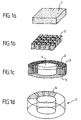
- Figures 1a to 1d show the different steps of the general manufacturing process of such a piezoelectric composite ring to be used in a piezomotor, starting from a piezoelectric ceramic plate 1 (Fig. 1a).
- the piezoelectric ceramic plate is cut in a plurality of piezoelectric ceramic elements 2 with a regular periodicity (Fig. 1b).
- the piezoelectric elements are square pillars, however, the section of the piezoelectric ceramic elements in the horizontal plan may have a rectangular or even a circular shape, or any kind of shape, as for instance, the same shape as the electrode ones.
- the manufacturing of the pillars may not comprise the cutting from a ceramic plate, but rather individual forming techniques.
- the cross-section of all the piezoelectric ceramic elements is defined in accordance with the specificity of the final piezomotor.
- the dimension of the cross-section of these elements is optimized so as to be in a particular relationship to the wavelength of the generated progressive wave on the surface of the transducer.
- the radius or one side of a square-section can be in the order of one tenth of the wavelength.
- the height of the piezoelectric elements is adjusted in such a manner to keep sufficient width/height ratio (or aspect ratio).
- the space between the piezoelectric ceramic elements is then filled with a matrix material 3 such as, for instance, polymer, and in particular, epoxy resins and/or plastic like material.
- a matrix material 3 such as, for instance, polymer, and in particular, epoxy resins and/or plastic like material.
- the ratio of the volume of the piezoelectric ceramic elements to the volume of the total piezoelectric transducer is higher than 20%.
- the piezoelectric composite is either cast in a ring mold or formed as a web which may then be cut into ring shape 5 (Fig. 1c) with a center opening 4.
- the surfaces of the ring 5 can be polished to improve the flatness, in order to optimize the mechanical coupling of the piezoelectric composite ring and stator. It is conceivable, of course, to produce motors with different geometry where the transducers may have non planar shapes, as spherical or cylindrical shapes.
- the ceramic is cut as illustrated in Fig. 1b, filled and formed to the appropriate shape by the same forming method.
- electrodes 6 are then deposited on both sides of the transducer in a known metallization process. With such a process, the shape of the electrodes can be optimized. Then, the piezoelectric elements are polarized with a high voltage, e.g. several thousands Volts.
- FIG. 2 A first embodiment of a piezomotor according to the present invention will be described now in conjunction with Fig. 2.
- a piezoelectric ring 7 is sandwiched between a rigid part of stator 8 and a deformable part of the stator 8' by means of screws 8a (in dotted vertical lines on the figure) or by any other means of a known assembling method.
- a rotor 9 which is attached to the driving shaft 10 of the piezomotor is pressed against the upper surface of the deformable part of the stator 8' with known pressing means (not shown), and a friction layer 9' made of polymer type is material is used to insure the contact between the rotor 9 and the stator part 8'.
- This friction layer is made of suitable mixture of polymers and solid lubricants as for instance Teflon (for polytetrafluorethylene) or PEEK (for polyetheretherketone) type material, in order to set the coefficient of friction.
- Teflon for polytetrafluorethylene
- PEEK for polyetheretherketone
- the use of such material in the friction layer decrease the wear of interface between rotor and stator.
- An insulating ring 7a located between the surface electrode 6 and the stator 8 permits also to connect the surface electrode 6 to an electronic circuit (not shown) through conductor film deposited on the face in contact with the surface electrodes 6.
- the ring 7a could be typically printed circuit type ring.
- the electronic control device supplies a first set and a second set of electrodes 6 with a sinus-type voltage and a cosinus-type voltage, respectively.
- the two sinusoidal voltages have the same frequency and are ⁇ /2 out of phase from each other, and the the electrodes are ⁇ /4 spaced ( ⁇ being the wavelength of the deformation wave), in order to generate a progressive wave over the surface of the piezoelectric composite ring 7.
- the sinusoidal voltages create the axial vibrations along axis AA' of each piezoelectric element 2 of the composite material, with the appropriate phase to generate two standing waves, the progressive wave resulting from the superposition of these two standing waves.
- the surface points of the stator perform an elliptical motion which generates the torque that creates a relative rotation between the stator 8 and the rotor 9.
- the piezoelectric composite ring 7 can be pre-pressed against the stator 8 by using screws 8a.
- the piezomotor according to the present invention combines the main advantages of the two cited prior art types of piezomotors, i.e. the high axial amplitudes of the piezoelectric elements 2 that work in contraction and extension parallel to the axis of symmetry of the motor, and the elasticity of the matrix polymer 3. Because of the good flexibility of the piezoelectric transducer, the piezomotor can be driven at the resonant frequency of the piezoelectric transducer without any risk of breaking the transducer.
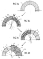
- Fig. 3a shows a ring-shaped piezoelectric material plate 1.
- Fig. 3b is a half view of a piezoelectric composite ring 5 used in the piezomotor of the second embodiment. The right side shows a quarter of the piezoelectric composite material formed of piezoelectric elements 2 obtained by cutting the plate 1 of Fig. 3a.
- they have a ⁇ /12 section area and are embedded within a polymer matrix 3, however, they may have, for instance, any section area in the range of ⁇ /4 to ⁇ /20.
- the piezoelectric composite ring 5 is divided into twelve sectors for receiving twelve surface electrodes 6 which have a ⁇ /4 area, as it is shown in Fig. 3b and 3c. Each surface electrode is separate from the adjacent electrodes by an insulating space 3 which corresponds to a matrix polymer area on the piezoelectric composite ring 5.
- each of the 2x6 electrodes is connected to one of e.g. six piezoelectric elements, the number of piezoelements can obviously be different from six. In the same way, the number of surface electrodes is not limited to twelve.
- the first set and the second set of electrodes have to be connected to a phase-shift circuit (not shown) through first external and second internal conductive plates 11 and 12, respectively.
- These conductive plates can be copper plates and extend over the surface electrodes like two circular interleaving combs.
- Fig. 4 shows a piezoelectric motor according to the invention using a piezoelectric transducer 23 centered on the axis of symmetry AA' of the motor.
- the stator comprises a deformable portion 13 and a rigid portion 14 & 22 mounted in a rotating way on the driving shaft 15.
- the driving shaft 15 is attached to the rotor 16 which is pre-pressed against the deformable portion 13, advantageously through a friction layer of the type above described, by a nut 17 and a spring 18.
- the narrow upper surface of the periphery of the deformable portion 13 is in contact with the rotor 16 through friction layer 19.
- the upper surface of the flexible portion 13 which is in contact with the rotor 16 can be designed in a plurality of teeth (not shown) in order to maximize the speed of the rotor.
- the piezoelectric transducer 23 of this preferred embodiment is made of two stacked piezoelectric composite rings 20 and 20' having their external and internal conductive plates 11 and 12 in common. This stack can consist in more than two stacked piezoelectric composite rings as shown in Fig. 5c. A stack of rings has the advantage to reduce the required input voltage.
- the piezoelectric transducer 23 is globally pre-pressed against the underside of the flexible portion 13 of the stator by a base 22 which is screwed or mounted with a pressing nut (not shown) on the rigid portion 14 of the stator. In a different embodiment, the pre-pressing of the piezoelectric transducer 23 can obviously be made by different individual screws through the base 22.
- the piezoelectric transducer is pre-pressed through an intermediate plate ring, or directly against the underside surface of the piezoelectric composite ring 23 or against recesses previously made in the piezoelectric composite ring 23.
- the flexible portion 13 of the stator and the base 22 being in electrical contact with each other, constitute the ground.
- the flexible portion 13 of the stator is exited by the axial vibrations of the piezoelectric elements 2 created by the suitable voltages applied to the electrodes 6 via the external and internal conductive plates 11 and 12.
- the rotor 16 is driven by the generated elliptical motion of each point of the friction area at the periphery of the flexible portion 13.
- the torque transmission between stator and rotor is optimized due to this particular double-stacked piezoelectric composite ring structure of the piezoelectric transducer, the shape of the deformable portion which extend from the friction zone to the rigid portion, and the lever-arm effect between the rigid portion and the periphery of the flexible portion of the stator.
- Fig. 5a shows a section view of a first example of a piezoelectric composite transducer 20 (or 7) made of a matrix polymer 3 and piezoelectric elements 2 connected on one side to surface electrodes 11 and 12.
- Fig 5b shows a second example of a piezoelectric composite transducer 23 made of a stack of two piezoelectric composite rings, both connected on one side to an outside phase-shift circuit through surface electrodes 11 and 12, as used in the piezomotor of Fig. 4.
- Fig. 5c shows a third example of a piezoelectric composite transducer 24 made of a stack of a plurality of piezoelectric composite rings 20i of the type shown in Fig. 3d.
- Each ring 20i shares first surface electrodes on one side with an adjacent ring, connected to electrode 11 or 12 through a vertical electrode portion 11a or 12a, and second surface electrodes on the other side with an adjacent ring, connected to the vertical ground electrode portion 25. That is, ground electrode 25 and polarization electrodes 11 and 12 are alternatively connected to the horizontal electrodes of the multilayer piezoelectric composite transducer shown in Fig. 5c.
- piezoelectric composite transducers may be used in both piezoelectric motors of first and second embodiments of figures 2 and 4, respectively.
- the present invention is not limited to the above described embodiments, but can be adjusted to and implemented in all types of piezomotors, with one or two driving rotors which are attached to each other (known as ⁇ butterfly ⁇ structures).
- the piezoelectric transducer can be comprised of a plurality of portions cut from a piezoelectric composite structure, such as e.g. sectors which are assembled in a piezoelectric composite ring as described above.
- the piezomotor according to the invention is light, compact and quiet. It can be instantaneously stopped and started (in about 1 ms), and can be miniaturized. It can be manufactured without any manipulation of small elements and allows simple electrode positioning.
- the manufacturing method is easy to implement, and piezomotors can be mass-produced inexpensively. Global pre-stress can be applied accurately, and the final mounting of the piezomotor according to the present invention is simplified. Consequently, the manufacturing cost is reduced.
- the present invention is particularly well adapted to small-sized motors, and, for instance, for driving headrests in cars, focus adjustment or zoom in photo-cameras, for watches, or in any type of apparatus which requires a small, light, silent and strong motor.
Landscapes
- General Electrical Machinery Utilizing Piezoelectricity, Electrostriction Or Magnetostriction (AREA)
Abstract
This invention relates to a piezoelectric motor having a piezoelectric
transducer made of a piezoelectric composite element, and more particularly to
a piezomotor comprising a stator (13,14,22), a rotor (16) and a piezoelectric
transducer (23). The piezoelectric transducer (23) is attached to the stator
(13,14,22) and carries surface electrodes which are connected to a control
circuit, in order to generate a progressive wave over the surface of the
piezoelectric transducer (23). The piezoelectric transducer (23) is made of at
least one composite material (20,20') which is formed by a plurality of
separate piezoelectric elements (2) embedded into a matrix material (3) having
an elastic modulus lower than the one of the piezoelectric elements (2).
This type of piezomotor transducer allows to miniaturize a piezomotor
due to simpler handling of the transducer in its entirely rather than of
individual miniaturized elements, and also improves the flexibility of the
transducer.
Description
This invention relates to a piezoelectric motor comprising a stator, a
rotor and a piezoelectric transducer, said piezoelectric transducer being
attached to the stator and holding surface electrodes which are connected to a
control circuit, in order to generate a progressive wave over the surface of the
piezoelectric transducer. This invention also relates to methods for
manufacturing piezoelectric transducers to be used in such a piezoelectric
motor.
Piezomotors are used instead of electromagnetic motors in many
applications as electromagnetic motors are big, heavy and noisy, and have
complicated structures due to the wiring. Piezomotors use the properties of
piezoelectric materials, like ceramics, as an electromechanical transducer. A
progressive wave is generated on the surface of the piezoelectric transducer,
constituted by the superposition of two standing waves out of phase from each
other and generated by two sets of electrodes. The motion of each point of the
stator surface is elliptical and drives the rotor.
A first type of piezomotor comprises a ring-shaped piezoelectric
element on which a plurality of electrodes are cemented to the surface. The
electrodes are connected to a control circuit through a phase shifter. By
applying high frequency voltages out of phase from each other, a single-directional
surface wave (progressive wave) can be generated on the
piezoelectric element which vibrates in flexural mode. An example of such a
piezomotor is disclosed in US patent n° 4,562,374 of Sashida et al. This type
of piezomotor has limited power, as the amplitudes of the ring-shaped
piezoelectric element's vibrations are small and the ring-shaped element may
brake at the resonance frequency. When trying to increase the input power,
overheating of the area of friction can damage the piezoelectric properties of
the element and the bonding between the piezoelectric ring and the stator, and
consequently the life time of the motor is reduced.
A second known type of piezomotor solves some of the above
mentioned problems, using ceramic pillars instead of ring-shaped ceramics.
The stator has a deformable portion which is in contact with a portion of the
rotor through a friction area and is controlled by a plurality of independent
ceramic pillars. The ceramic pillars are driven in separate sets in order to
obtain a progressive wave and each set of ceramic pillars is set off in rotary
direction by a quarter of a wavelength from the other and connected to a
control circuit which generates a progressive wave to insure the driving of the
rotor. Each ceramic pillar can be individually, adjustably and axially pre-stressed
against the deformable portion with a screw. The structure of this
piezomotor is more complicated and delicate to set, but such a piezomotor has
high torque compared to the above described one. In this case the ceramics are
vibrating in an axial mode (known as d3-3 mode) which presents a higher
electromechanical coupling factor for piezoelectric conversion, and which
produces a higher stress limit, compared to the above mentioned flexural
mode. An example of this type of piezomotor is disclosed, for instance, in
French patent n° 2 715 780, filed on February 1, 1994 in the name of IMRA.
The individual piezoelectric elements can also be made of piezoelectric sectors
cut in a piezoelectric ring, with individual pre-stress or global pre-stress. As
the flatness of the surface of the piezoelectric elements is not optimized, the
efficiency of the motor cannot be maximized. In addition, the miniaturization
of such an improved piezomotor (smaller than 5 mm) raises some problems as,
for instance, the mounting of the miniaturized piezoelements, their accurate
positioning on the stator and the setting of their individual pre-stresses. In case
of global pre-stress, high precision of the thickness of the piezoelements is
required, to assure precise coupling between the piezoelements and the stator
in order to avoid variable individual pre-stress. This further increases the cost
of a miniaturized piezomotor with individual piezoelement technology.
Therefore, there is an important need to develop a new type of
piezoelectric transducer for a piezomotor, which is not subject to the above
mentioned problems and which can be miniaturized while keeping a high
torque and low manufacturing cost and which is easy to manufacture.
Recently, piezoelectric ceramics/polymer composite structures have
been used in some ultrasonic transducers for underwater sonar and medical
diagnostics. The articles 〈〈 Computation of hydrostatic piezoelectric
coefficients for 1-3 composites by the finite-element method〉〉 of B.C. Shin
(Sensors and Actuators A, 40 (1994), page 191-194) and 〈〈 Finite element
modeling of active periodic structures : Application to 1-3 piezocomposites〉〉
of A.C. Hladky-Hennion and J-N. Decarpigny (Journal of Acoustical Society
of America 1994 (2), Pt. 1, August 1993) disclose some applications of this
type of composite materials in sonar, underwater communications, underwater
or medical imaging. Patent EP 0 595 849, of Technomed, discloses a
therapeutic medical application. However, the type of composite transducers
proposed in these publications are unfit to be used in a piezomotor where they
would not produce the desired effects.
The main object of the present invention is to propose such an improved
piezomotor.
This object is achieved by a piezoelectric motor of the type as described
above which is characterized in that said piezoelectric transducer is made of at
least one composite material which is formed of a plurality of piezoelectric
elements embedded into a matrix material having an elastic modulus lower
than the one of the piezoelectric elements.
In one embodiment of the present invention, the piezoelectric elements
are parallelepipedical or cylindrical ceramic elements, which are all parallel to
the axis of symmetry of a ring-shaped piezoelectric transducer and they are all
arranged on the same plane. The matrix material can be a polymer material as
resin and/or plastic like material, and the piezoelectric transducer is ring-shaped.
In this case, the piezoelectric elements are disposed and sized in such a
way that they vibrate in axial direction of the piezomotor.
In addition, the piezoelectric elements have a cross-sectional dimension
in the plane of the piezoelectric composite surface in the order of one tenth of
the wavelength (or higher) of the progressive wave which is generated by the
application of an oscillating polarization voltage.
Preferably, the piezoelectric transducer is made of a plurality of stacked
piezoelectric composite rings.
Further, in a preferred embodiment of the present invention, the
piezoelectric elements in the composite transducer account for higher than
20% of the total volume of the piezoelectric transducer.
This particular piezoelectric transducer can be globally pre-stressed or
locally pre-stressed through a plurality of screws on the stator.
The piezoelectric transducer used in the present invention can be
manufactured by a process comprising the steps of :
- cutting a piezoelectric ceramic plate in a plurality of piezoelectric ceramic elements with a regular periodicity,
- filling the space between the piezoelectric ceramic elements with polymer, to get a piezoelectric composite material plate,
- cutting the piezoelectric composite material plate into a ring shape,
- polishing both faces of said piezoelectric composite material ring,
- depositing electrodes on both polished sides of the piezoelectric composite material ring, and
- polarizing the piezoelectric ceramic elements.
Another embodiment of the process for manufacturing a piezoelectric
transducer according to the invention, comprises the steps of :
- cutting a piezoelectric ceramic material in a ring shape,
- cutting the piezoelectric ceramic material ring in a plurality of piezoelectric ceramic elements with a regular periodicity,
- filling the space between the piezoelectric ceramic elements with polymer, to get a piezoelectric composite material ring,
- polishing both faces of said piezoelectric composite material ring,
- depositing electrodes on both polished sides of the piezoelectric composite material ring, and
- polarizing the piezoelectric ceramic elements.
Additional objects and features of the invention will appear from the
following description in which the preferred embodiments are set forth in
detail in connection with the accompanying drawings.
- Figures 1a to 1d are perspective views of the different steps of a general fabrication process of a piezoelectric transducer according to a first embodiment of the present invention,
- Figure 2 is a section view of a piezomotor using a piezoelectric transducer of the type of figure 1d, according to a first embodiment of the present invention,
- Figures 3a to 3d are partial views of the different steps of a fabrication process of a particular piezoelectric composite transducer which can be used in a piezoelectric motor according to the present invention,
- Figure 4 is a section view of a piezomotor according to a second embodiment of the present invention, and
- Figures 5a to 5c are a cross section of three examples of piezoelectric composite transducers which can be used in a piezoelectric composite motor according to the present invention.
The same elements appearing in the different figures, keep the same
symbols or reference numbers.
In the present application a piezoelectric composite material is defined
as being a combination of piezoelectric elements, like, for instance,
piezoelectric ceramic elements, with a passive non-piezoelectric polymer
having a lower elastic modulus like, for instance, epoxy resins and/or plastic
like material. The particular type of piezoelectric composite material that will
be described in the preferred embodiment, is known as having a connectivity
of 1-3, i.e. a composite consisting of rods of piezoceramic extending from one
electrode to the other and embedded in polymer, and working in a
compression/extension d3-3 mode. Figures 1a to 1d show the different steps of
the general manufacturing process of such a piezoelectric composite ring to be
used in a piezomotor, starting from a piezoelectric ceramic plate 1 (Fig. 1a).
The piezoelectric ceramic plate is cut in a plurality of piezoelectric
ceramic elements 2 with a regular periodicity (Fig. 1b). In this embodiment,
the piezoelectric elements are square pillars, however, the section of the
piezoelectric ceramic elements in the horizontal plan may have a rectangular or
even a circular shape, or any kind of shape, as for instance, the same shape as
the electrode ones. In the two latter cases, however, the manufacturing of the
pillars may not comprise the cutting from a ceramic plate, but rather individual
forming techniques.
The cross-section of all the piezoelectric ceramic elements is defined in
accordance with the specificity of the final piezomotor. Preferably, the
dimension of the cross-section of these elements is optimized so as to be in a
particular relationship to the wavelength of the generated progressive wave on
the surface of the transducer. For instance, the radius or one side of a square-section
can be in the order of one tenth of the wavelength. The height of the
piezoelectric elements is adjusted in such a manner to keep sufficient
width/height ratio (or aspect ratio).
The space between the piezoelectric ceramic elements is then filled with
a matrix material 3 such as, for instance, polymer, and in particular, epoxy
resins and/or plastic like material. Preferably, the ratio of the volume of the
piezoelectric ceramic elements to the volume of the total piezoelectric
transducer is higher than 20%.
In the present embodiment, the piezoelectric composite is either cast in
a ring mold or formed as a web which may then be cut into ring shape 5 (Fig.
1c) with a center opening 4. The surfaces of the ring 5 can be polished to
improve the flatness, in order to optimize the mechanical coupling of the
piezoelectric composite ring and stator. It is conceivable, of course, to produce
motors with different geometry where the transducers may have non planar
shapes, as spherical or cylindrical shapes. For this purpose, the ceramic is cut
as illustrated in Fig. 1b, filled and formed to the appropriate shape by the same
forming method.
In order to implement the piezoelectric composite transducer 7 in a
motor according to the invention, electrodes 6 are then deposited on both sides
of the transducer in a known metallization process. With such a process, the
shape of the electrodes can be optimized. Then, the piezoelectric elements are
polarized with a high voltage, e.g. several thousands Volts.
A first embodiment of a piezomotor according to the present invention
will be described now in conjunction with Fig. 2. In Fig. 2, a piezoelectric ring
7 is sandwiched between a rigid part of stator 8 and a deformable part of the
stator 8' by means of screws 8a (in dotted vertical lines on the figure) or by
any other means of a known assembling method. A rotor 9 which is attached to
the driving shaft 10 of the piezomotor is pressed against the upper surface of
the deformable part of the stator 8' with known pressing means (not shown),
and a friction layer 9' made of polymer type is material is used to insure the
contact between the rotor 9 and the stator part 8'. This friction layer is made of
suitable mixture of polymers and solid lubricants as for instance Teflon (for
polytetrafluorethylene) or PEEK (for polyetheretherketone) type material, in
order to set the coefficient of friction. The use of such material in the friction
layer decrease the wear of interface between rotor and stator. An insulating
ring 7a located between the surface electrode 6 and the stator 8 permits also to
connect the surface electrode 6 to an electronic circuit (not shown) through
conductor film deposited on the face in contact with the surface electrodes 6.
The ring 7a could be typically printed circuit type ring.
For instance, the electronic control device supplies a first set and a
second set of electrodes 6 with a sinus-type voltage and a cosinus-type voltage,
respectively. The two sinusoidal voltages have the same frequency and are π/2
out of phase from each other, and the the electrodes are λ/4 spaced (λ being
the wavelength of the deformation wave), in order to generate a progressive
wave over the surface of the piezoelectric composite ring 7. The sinusoidal
voltages create the axial vibrations along axis AA' of each piezoelectric
element 2 of the composite material, with the appropriate phase to generate
two standing waves, the progressive wave resulting from the superposition of
these two standing waves. The surface points of the stator perform an elliptical
motion which generates the torque that creates a relative rotation between the
stator 8 and the rotor 9. The piezoelectric composite ring 7 can be pre-pressed
against the stator 8 by using screws 8a.
The piezomotor according to the present invention combines the main
advantages of the two cited prior art types of piezomotors, i.e. the high axial
amplitudes of the piezoelectric elements 2 that work in contraction and
extension parallel to the axis of symmetry of the motor, and the elasticity of
the matrix polymer 3. Because of the good flexibility of the piezoelectric
transducer, the piezomotor can be driven at the resonant frequency of the
piezoelectric transducer without any risk of breaking the transducer.
A second embodiment of a piezomotor according to the present
invention will be described now in conjunction with Fig. 3a to 3c and Fig. 4.
Fig. 3a shows a ring-shaped piezoelectric material plate 1. Fig. 3b is a
half view of a piezoelectric composite ring 5 used in the piezomotor of the
second embodiment. The right side shows a quarter of the piezoelectric
composite material formed of piezoelectric elements 2 obtained by cutting the
plate 1 of Fig. 3a. In Fig.3b, they have a λ/12 section area and are embedded
within a polymer matrix 3, however, they may have, for instance, any section
area in the range of λ/4 to λ/20. In this embodiment, the piezoelectric
composite ring 5 is divided into twelve sectors for receiving twelve surface
electrodes 6 which have a λ/4 area, as it is shown in Fig. 3b and 3c. Each
surface electrode is separate from the adjacent electrodes by an insulating
space 3 which corresponds to a matrix polymer area on the piezoelectric
composite ring 5.
In this particular embodiment, there are two sets of surface electrodes 6
whereby the electrodes of one set are connected in parallel to the same voltage
supply. Along the periphery of the transducer the electrodes of one set are
arranged alternatively with the electrodes of the other set. Each of the 2x6
electrodes is connected to one of e.g. six piezoelectric elements, the number of
piezoelements can obviously be different from six. In the same way, the
number of surface electrodes is not limited to twelve.
In accordance with the type of electric control applied to the
piezoelectric composite transducer 20 of Fig. 3d, the first set and the second
set of electrodes have to be connected to a phase-shift circuit (not shown)
through first external and second internal conductive plates 11 and 12,
respectively. These conductive plates can be copper plates and extend over the
surface electrodes like two circular interleaving combs.
Fig. 4 shows a piezoelectric motor according to the invention using a
piezoelectric transducer 23 centered on the axis of symmetry AA' of the
motor. The stator comprises a deformable portion 13 and a rigid portion 14 &
22 mounted in a rotating way on the driving shaft 15. The driving shaft 15 is
attached to the rotor 16 which is pre-pressed against the deformable portion
13, advantageously through a friction layer of the type above described, by a
nut 17 and a spring 18. The narrow upper surface of the periphery of the
deformable portion 13 is in contact with the rotor 16 through friction layer 19.
The upper surface of the flexible portion 13 which is in contact with the rotor
16 can be designed in a plurality of teeth (not shown) in order to maximize the
speed of the rotor.
The piezoelectric transducer 23 of this preferred embodiment is made of
two stacked piezoelectric composite rings 20 and 20' having their external and
internal conductive plates 11 and 12 in common. This stack can consist in
more than two stacked piezoelectric composite rings as shown in Fig. 5c. A
stack of rings has the advantage to reduce the required input voltage. The
piezoelectric transducer 23 is globally pre-pressed against the underside of the
flexible portion 13 of the stator by a base 22 which is screwed or mounted with
a pressing nut (not shown) on the rigid portion 14 of the stator. In a different
embodiment, the pre-pressing of the piezoelectric transducer 23 can obviously
be made by different individual screws through the base 22. In the latter case,
the piezoelectric transducer is pre-pressed through an intermediate plate ring,
or directly against the underside surface of the piezoelectric composite ring 23
or against recesses previously made in the piezoelectric composite ring 23. The
flexible portion 13 of the stator and the base 22 being in electrical contact with
each other, constitute the ground.
The flexible portion 13 of the stator is exited by the axial vibrations of
the piezoelectric elements 2 created by the suitable voltages applied to the
electrodes 6 via the external and internal conductive plates 11 and 12. The
rotor 16 is driven by the generated elliptical motion of each point of the
friction area at the periphery of the flexible portion 13. The torque
transmission between stator and rotor is optimized due to this particular
double-stacked piezoelectric composite ring structure of the piezoelectric
transducer, the shape of the deformable portion which extend from the friction
zone to the rigid portion, and the lever-arm effect between the rigid portion
and the periphery of the flexible portion of the stator.
Fig. 5a shows a section view of a first example of a piezoelectric
composite transducer 20 (or 7) made of a matrix polymer 3 and piezoelectric
elements 2 connected on one side to surface electrodes 11 and 12. Fig 5b
shows a second example of a piezoelectric composite transducer 23 made of a
stack of two piezoelectric composite rings, both connected on one side to an
outside phase-shift circuit through surface electrodes 11 and 12, as used in the
piezomotor of Fig. 4.
Fig. 5c shows a third example of a piezoelectric composite transducer
24 made of a stack of a plurality of piezoelectric composite rings 20i of the
type shown in Fig. 3d. Each ring 20i shares first surface electrodes on one side
with an adjacent ring, connected to electrode 11 or 12 through a vertical
electrode portion 11a or 12a, and second surface electrodes on the other side
with an adjacent ring, connected to the vertical ground electrode portion 25.
That is, ground electrode 25 and polarization electrodes 11 and 12 are
alternatively connected to the horizontal electrodes of the multilayer
piezoelectric composite transducer shown in Fig. 5c.
These three examples of piezoelectric composite transducers may be
used in both piezoelectric motors of first and second embodiments of figures 2
and 4, respectively.
The present invention is not limited to the above described
embodiments, but can be adjusted to and implemented in all types of
piezomotors, with one or two driving rotors which are attached to each other
(known as 〈〈 butterfly 〉〉 structures). The piezoelectric transducer can be
comprised of a plurality of portions cut from a piezoelectric composite
structure, such as e.g. sectors which are assembled in a piezoelectric composite
ring as described above.
The piezomotor according to the invention is light, compact and quiet.
It can be instantaneously stopped and started (in about 1 ms), and can be
miniaturized. It can be manufactured without any manipulation of small
elements and allows simple electrode positioning. The manufacturing method
is easy to implement, and piezomotors can be mass-produced inexpensively.
Global pre-stress can be applied accurately, and the final mounting of the
piezomotor according to the present invention is simplified. Consequently, the
manufacturing cost is reduced.
The present invention is particularly well adapted to small-sized motors,
and, for instance, for driving headrests in cars, focus adjustment or zoom in
photo-cameras, for watches, or in any type of apparatus which requires a small,
light, silent and strong motor.
Claims (13)
- A piezoelectric motor comprising a stator (8;13,14,22), a rotor (9;16) and a piezoelectric transducer (7;20;23;24), said piezoelectric transducer (7;20;23;24) being attached to the stator (8;13,14,22) and holding surface electrodes (6) which are connected to a control circuit, in order to generate a progressive wave over the surface of the piezoelectric transducer (7;20;23;24), characterized in that said piezoelectric transducer (7;20;23;24) is made of at least one composite material which is formed of a plurality of separate piezoelectric elements (2) embedded into a matrix material (3) having an elastic modulus lower than the one of the piezoelectric elements (2).
- A piezoelectric motor according to claim 1, characterized in that the piezoelectric elements (2) are ceramic elements.
- A piezoelectric motor according to claim 1 or 2, characterized in that the matrix material (3) is a polymer material.
- A piezoelectric motor according to claim 3, characterized in that the polymer material is epoxy resins and/or plastic like material.
- A piezoelectric motor according to one of the preceding claims, characterized in that the piezoelectric transducer (23;24) is made of a plurality of piezoelectric composite rings (20i).
- A piezoelectric motor according to one of the preceding claims, characterized in that the piezoelectric elements (2) vibrate in the axial direction (AA') of the piezomotor.
- A piezoelectric motor according to one of the preceding claims, characterized in that the piezoelectric elements (2) have a cross-sectional dimension in the plane of the piezoelectric composite surface in the order of one tenth of the wavelength (λ) of the produced progressive wave.
- A piezoelectric motor according to one of the preceding claims, characterized in that the total volume of the piezoelectric elements (2) forms at least 20% of the volume of the composite piezoelectric transducer (7;20;23;24).
- A piezoelectric motor according to one of the preceding claims, characterized in that the piezoelectric transducer (7;20;23;24) is globally pre-pressed between the stator (8;13,14) and the rotor (9;16).
- A piezoelectric motor according to one of claims 1 to 8, characterized in that the piezoelectric transducer is pre-pressed with a plurality of screws.
- A piezoelectric motor according to claim 6, characterized in that the piezoelectric elements (2) are parallelepipedical or cylindrical elements which are all parallel to the axis of symmetry (AA') of the ring-shaped piezoelectric transducer (7;20;20i).
- A method for manufacturing a piezoelectric transducer (7;20;23;24) to be used in a piezoelectric motor, comprising the steps of :cutting a piezoelectric ceramic plate (1) in a plurality of piezoelectric ceramic elements (2) with a regular periodicity,filling the space between the piezoelectric ceramic elements with polymer (3), to get a piezoelectric composite material plate,cutting the piezoelectric composite material plate into a ring shape (5),polishing both faces of said piezoelectric composite material ring,depositing electrodes (6) on both polished sides of the piezoelectric composite material ring (5), andpolarizing the piezoelectric ceramic elements (2).
- A method for manufacturing a piezoelectric transducer (7;20;23;24) to be used in a piezoelectric motor, comprising the steps of :cutting a piezoelectric ceramic material in a ring shape,cutting the piezoelectric ceramic material ring in a plurality of piezoelectric ceramic elements (2) with a regular periodicity,filling the space between the piezoelectric ceramic elements with polymer (3), to get a piezoelectric composite material ring (5),polishing both faces of said piezoelectric composite material ring (5),depositing electrodes (6) on both polished sides of the piezoelectric composite material ring (5), andpolarizing the piezoelectric ceramic elements (2).
Priority Applications (1)
| Application Number | Priority Date | Filing Date | Title |
|---|---|---|---|
| EP97109649A EP0884832A1 (en) | 1997-06-13 | 1997-06-13 | Piezomotor with a piezoelectric composite transducer, and method for manufacturing such a transducer |
Applications Claiming Priority (1)
| Application Number | Priority Date | Filing Date | Title |
|---|---|---|---|
| EP97109649A EP0884832A1 (en) | 1997-06-13 | 1997-06-13 | Piezomotor with a piezoelectric composite transducer, and method for manufacturing such a transducer |
Publications (1)
| Publication Number | Publication Date |
|---|---|
| EP0884832A1 true EP0884832A1 (en) | 1998-12-16 |
Family
ID=8226912
Family Applications (1)
| Application Number | Title | Priority Date | Filing Date |
|---|---|---|---|
| EP97109649A Withdrawn EP0884832A1 (en) | 1997-06-13 | 1997-06-13 | Piezomotor with a piezoelectric composite transducer, and method for manufacturing such a transducer |
Country Status (1)
| Country | Link |
|---|---|
| EP (1) | EP0884832A1 (en) |
Cited By (2)
| Publication number | Priority date | Publication date | Assignee | Title |
|---|---|---|---|---|
| EP1914815A1 (en) | 2006-10-19 | 2008-04-23 | SAGEM Défense Sécurité | Turret with positioning in two axes and piezoelectric motorisation |
| CN111682795A (en) * | 2020-06-12 | 2020-09-18 | 南京航达超控科技有限公司 | Rotary traveling wave ultrasonic motor with backup function and drive control method thereof |
Citations (2)
| Publication number | Priority date | Publication date | Assignee | Title |
|---|---|---|---|---|
| US4801835A (en) * | 1986-10-06 | 1989-01-31 | Hitachi Medical Corp. | Ultrasonic probe using piezoelectric composite material |
| US5493164A (en) * | 1993-07-30 | 1996-02-20 | Crouzet Automatismes S.A. | Surface acoustic wave motor |
-
1997
- 1997-06-13 EP EP97109649A patent/EP0884832A1/en not_active Withdrawn
Patent Citations (2)
| Publication number | Priority date | Publication date | Assignee | Title |
|---|---|---|---|---|
| US4801835A (en) * | 1986-10-06 | 1989-01-31 | Hitachi Medical Corp. | Ultrasonic probe using piezoelectric composite material |
| US5493164A (en) * | 1993-07-30 | 1996-02-20 | Crouzet Automatismes S.A. | Surface acoustic wave motor |
Cited By (4)
| Publication number | Priority date | Publication date | Assignee | Title |
|---|---|---|---|---|
| EP1914815A1 (en) | 2006-10-19 | 2008-04-23 | SAGEM Défense Sécurité | Turret with positioning in two axes and piezoelectric motorisation |
| US7573624B2 (en) | 2006-10-19 | 2009-08-11 | Sagem Defense Securite | Piezoelectric-motor-driven two-axis orientation turret |
| CN111682795A (en) * | 2020-06-12 | 2020-09-18 | 南京航达超控科技有限公司 | Rotary traveling wave ultrasonic motor with backup function and drive control method thereof |
| CN111682795B (en) * | 2020-06-12 | 2022-09-27 | 南京航达超控科技有限公司 | Rotary traveling wave ultrasonic motor with backup function and drive control method thereof |
Similar Documents
| Publication | Publication Date | Title |
|---|---|---|
| Uchino | Piezoelectric ultrasonic motors: overview | |
| JP3118251B2 (en) | Ultrasonic driving device and method | |
| JP4648391B2 (en) | Miniaturizable motor | |
| JP3311446B2 (en) | Ultrasonic motor | |
| US20100197205A1 (en) | Grinding device using ultrasonic vibration | |
| JP4697929B2 (en) | Multilayer piezoelectric element and vibration wave drive device | |
| US6114798A (en) | Stacked element and vibration drive device | |
| CN108429486A (en) | Combined flat surface 3-freedom ultrasonic motor oscillator and its driving method | |
| EP0884832A1 (en) | Piezomotor with a piezoelectric composite transducer, and method for manufacturing such a transducer | |
| JP2009183144A (en) | Ultrasonic motor, and electronic motor- equipped electronic appliance | |
| JP3353998B2 (en) | Ultrasonic transducer | |
| JPS63220782A (en) | Piezoelectric element | |
| JP2759804B2 (en) | Vibrator type actuator | |
| JP3805240B2 (en) | Ultrasonic motor | |
| JPH0628951Y2 (en) | Piezoelectric actuator | |
| JPH10507899A (en) | Traveling wave motor | |
| JPH05344759A (en) | Ultrasonic motor | |
| JPH0650949B2 (en) | Method for manufacturing piezoelectric actuator | |
| JP2650122B2 (en) | Vibrator type actuator | |
| JPH08163879A (en) | Ultrasonic oscillator and ultrasonic motor | |
| JP2759805B2 (en) | Vibrator type actuator | |
| JPH07178370A (en) | Vibrator and vibrating actuator | |
| JP2006320119A (en) | Ultrasonic motor | |
| JPH072229B2 (en) | Piezoelectric elliptical motion oscillator | |
| Koc et al. | Design of a piezoelectric ultrasonic motor for micro-robotic application |
Legal Events
| Date | Code | Title | Description |
|---|---|---|---|
| PUAI | Public reference made under article 153(3) epc to a published international application that has entered the european phase |
Free format text: ORIGINAL CODE: 0009012 |
|
| AK | Designated contracting states |
Kind code of ref document: A1 Designated state(s): AT BE CH DE FR GB IT LI LU MC NL SE |
|
| 17P | Request for examination filed |
Effective date: 19990401 |
|
| AKX | Designation fees paid |
Free format text: AT BE CH DE FR GB IT LI LU MC NL SE |
|
| STAA | Information on the status of an ep patent application or granted ep patent |
Free format text: STATUS: THE APPLICATION IS DEEMED TO BE WITHDRAWN |
|
| 18D | Application deemed to be withdrawn |
Effective date: 20021231 |