EP0884701B1 - Machine data acquisition system and method - Google Patents
Machine data acquisition system and method Download PDFInfo
- Publication number
- EP0884701B1 EP0884701B1 EP98109080A EP98109080A EP0884701B1 EP 0884701 B1 EP0884701 B1 EP 0884701B1 EP 98109080 A EP98109080 A EP 98109080A EP 98109080 A EP98109080 A EP 98109080A EP 0884701 B1 EP0884701 B1 EP 0884701B1
- Authority
- EP
- European Patent Office
- Prior art keywords
- data
- machine
- card
- storage
- information
- Prior art date
- Legal status (The legal status is an assumption and is not a legal conclusion. Google has not performed a legal analysis and makes no representation as to the accuracy of the status listed.)
- Expired - Lifetime
Links
Images






Classifications
-
- G—PHYSICS
- G07—CHECKING-DEVICES
- G07F—COIN-FREED OR LIKE APPARATUS
- G07F7/00—Mechanisms actuated by objects other than coins to free or to actuate vending, hiring, coin or paper currency dispensing or refunding apparatus
- G07F7/08—Mechanisms actuated by objects other than coins to free or to actuate vending, hiring, coin or paper currency dispensing or refunding apparatus by coded identity card or credit card or other personal identification means
- G07F7/10—Mechanisms actuated by objects other than coins to free or to actuate vending, hiring, coin or paper currency dispensing or refunding apparatus by coded identity card or credit card or other personal identification means together with a coded signal, e.g. in the form of personal identification information, like personal identification number [PIN] or biometric data
- G07F7/1008—Active credit-cards provided with means to personalise their use, e.g. with PIN-introduction/comparison system
-
- G—PHYSICS
- G06—COMPUTING OR CALCULATING; COUNTING
- G06Q—INFORMATION AND COMMUNICATION TECHNOLOGY [ICT] SPECIALLY ADAPTED FOR ADMINISTRATIVE, COMMERCIAL, FINANCIAL, MANAGERIAL OR SUPERVISORY PURPOSES; SYSTEMS OR METHODS SPECIALLY ADAPTED FOR ADMINISTRATIVE, COMMERCIAL, FINANCIAL, MANAGERIAL OR SUPERVISORY PURPOSES, NOT OTHERWISE PROVIDED FOR
- G06Q20/00—Payment architectures, schemes or protocols
- G06Q20/30—Payment architectures, schemes or protocols characterised by the use of specific devices or networks
- G06Q20/34—Payment architectures, schemes or protocols characterised by the use of specific devices or networks using cards, e.g. integrated circuit [IC] cards or magnetic cards
- G06Q20/346—Cards serving only as information carrier of service
-
- G—PHYSICS
- G07—CHECKING-DEVICES
- G07C—TIME OR ATTENDANCE REGISTERS; REGISTERING OR INDICATING THE WORKING OF MACHINES; GENERATING RANDOM NUMBERS; VOTING OR LOTTERY APPARATUS; ARRANGEMENTS, SYSTEMS OR APPARATUS FOR CHECKING NOT PROVIDED FOR ELSEWHERE
- G07C3/00—Registering or indicating the condition or the working of machines or other apparatus, other than vehicles
-
- G—PHYSICS
- G07—CHECKING-DEVICES
- G07F—COIN-FREED OR LIKE APPARATUS
- G07F9/00—Details other than those peculiar to special kinds or types of apparatus
- G07F9/02—Devices for alarm or indication, e.g. when empty; Advertising arrangements in coin-freed apparatus
Definitions
- the present invention relates to a system to provide services such as repair charge estimation and software upgrading with the use of an IC card containing data on electronic money and on the internal status of machines including PCs and household electrical appliances.
- the invention also relates to an IC card used in such a system.
- the system according to the present invention is used to acquire data on the internal status of a machine, and is used with an IC card having storage.
- This machine data acquisition system comprises an IC card accepting module for accepting the IC card; a machine data acquisition module for acquiring data on the internal status of the connected machine; and an IC card writing module for writing the data on the internal status of the machine acquired by the machine data acquisition module into the storage in the IC card.
- a machine according to the present invention is used with an IC card having storage.
- This machine comprises an IC card accepting module for accepting the IC card; a machine data acquisition module for acquiring data on the internal status of the machine; a writing module for writing the machine data acquired by the machine data acquisition module into the storage in the IC card; and a data sending module for sending data stored in the IC card over a communication line.
- machine-specific data may be stored previously in the storage in the UC card. This machine-specific data, as well as the acquired machine data, is sent over the communication line. Alternatively, only the machine-specific data may be sent.
- the machine-specific data can be machine guarantee data or machine disposal information (e.g. disposal method, parts materials).
- a machine data collection method of collecting data on the internal status of a machine comprises the steps of acquiring data on the internal status of the machine; recording the acquired data in an IC card; sending the machine status data over a communication line; and receiving the sent data.
- a terminal is used with an IC card containing sum information and machine data.
- This terminal comprises an IC card accepting module for accepting the IC card; a data reading module for reading data stored on the IC card; and a data sending module for sending, over a communication line, data read by the data reading module.
- An IC card according to the present invention is used with a machine whose internal status data is to be acquired.
- This IC card comprises sum information storage for storing sum information; and machine data storage for storing internal data on the machine.
- Another form of IC card according to the present invention comprises sum information storage for storing sum information; and disposal data storage for storing disposal data required when a machine is disposed of.
- a data processing system is used with an IC card on which sum information and software information are recorded.
- This data processing system comprises a storage module for storing a software; an IC card accepting module for accepting the IC card; a data reading module for reading data from the IC card; a sending module for sending, over a communication line, the software information read by the data reading module; a receiving module for receiving charge information required for upgrading the software, the charge information being sent in response to the sent software information; and a sum information sending module for sending sum information from the IC card, the sum information corresponding to the received charge information.
- a software upgrading method uses an IC card on which sum information and software information are recorded. This method first reads the software information and sends the read information over a communication line. Next, the method receives the information that was sent over a communication line and calculates a charge required for upgrading the software based on the received information. Next, the method sends the calculated charge information. Then, the method receives the charge information required for upgrading the software; and sends sum information from the IC card, the sum information corresponding to the received charge information.
- FIG. 1 is a diagram showing a system, one of the embodiments of the present invention, which diagnoses the status of the machines (component devices) of a personal computer. As shown in FIG. 1, this system includes an IC card 1 and a personal computer (hereafter called a PC) 7.
- a PC personal computer
- the IC card 1 comprises sum (cash value) information storage 2, ID storage 3, machine data storage 4, a processor 5, and a connector 6.
- the processor 5 is connected to the sum information storage 2, ID storage 3, machine data storage 4, and connector 6.
- the PC 7 comprises a machine data holding device 8, a modem 9, an IC card reader/writer 10, a central processing unit 11, a machine data check device 12, a display 13, a floppy disk drive (hereafter called an FDD) 14, a hard disk drive (hereafter called an HDD) 15, a CD-ROM drive (hereafter called a CD-ROM) 16, a RAM 17, a ROM 18, an input device 19, and a PCMCIA card interface (hereafter called PCMCIA) 20.
- the central processing unit 11 is connected to the machine data holding device 8, modem 9, IC card reader/writer 10, machine data check device 12, display 13, FDD 14, HDD 15, CD-ROM 16, RAM 17, ROM 18, input device 19, and PCMCIA 20.
- the machine data check device 12 is connected to the modem 9, central processing unit 11, display 13, FDD 14, HDD 15, CD-ROM 16, RAM 17, ROM 18, input device 19, and PCMCIA 20. As shown in FIG. 1, the central processing unit 11 and the machine data check device 12 are connected to the display 13, FDD 14, HDD 15, CD-ROM 16, RAM 17, ROM 18, input device 19, and PCMCIA 20 using one bus. However, they may be connected using separate signal lines.
- the machine data check device 12 When the user turns off the power of the PC 7, the machine data check device 12 reads the status of each machine and stores the machine status data in the machine data holding device 8.
- the machine data check device 12 may be designed so that it reads the status of each machine not only at the time of power-off but at a regular interval to store the status data into the machine data holding device 8. This keeps the machine data in the machine data holding device 8 up to date.
- the central processing unit 11 When the IC card 1 is connected to the PC 7 in this situation, the central processing unit 11 is informed of the connection of the IC card. Upon detecting the connection, the central processing unit 11 reads machine data from the machine data holding device 8 of the PC 7 and, via the card reader/writer 10, writes the machine data into the machine data storage 4 in the IC card 1.
- the system may also be designed so that, when the IC card 1 is already connected to the PC 7, machine data is stored not only into the machine data holding device 8 but also into the machine data storage 4 in the IC card 1.
- FIG. 2 shows an example of data stored in the machine data storage 4 in the IC card 1.
- the machine data storage 4 contains the name, machine specifications, model number, product number, and status (usage period, error status, error code, etc.) of each machine (component device) of the PC 7.
- the name, specifications, model number, and product number are written into the machine data storage 4 in the IC card, for example, by a PC store.
- the IC card containing such data comes with the PC.
- the "machine status" field in the machine data storage 4 holds the machine data on each machine read by the machine data check device 12.
- FIG. 3 shows an embodiment in which a PC 7 does not have a machine data holding device 8.
- the PC 7 shown in FIG. 3 is similar to the PC 7 shown in FIG. 1 except that the former does not have the machine data holding device 8.
- an IC card 1 is constantly connected to the PC 7, and machine data read by a machine data check device 12 is stored in machine data storage 4 in the IC card 1.
- central processing unit 11 and the machine data check device 12 are separate in the above embodiments, these two may be combined into one.
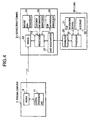
- FIG. 4 shows an example in which machine data is sent from the PC 7 to a service center terminal 21 when the PC fails.
- the service center terminal 21 comprises a modem 22, a processor 23, a machine data management unit 24, a customer information management unit 25, a sum information management unit 26, and a card reader/writer 27.
- An IC card 28 is also connected to the service center terminal 21.
- sum information having monetary values is transferred between IC cards.
- the IC card 28 comprises a connector 29, a processor 30, sum information storage 31, and ID storage 32.
- the user of the PC 7 accesses the service center terminal 21 installed in the service center, via the modem 9.
- the PC 7 sends machine data to the service center via the modem 9.
- the service center terminal 21 compares it with machine data stored in the machine data management unit 24 to identify the location and the cause of the error generated in the personal computer. Based on the comparison result, the service center terminal 21 estimates the repair charges and the required repair time, and sends the estimated result to the modem 9 at the user site over a telephone line.
- the estimated result sent from the service center over the telephone line is received by the modem 9 at the user site and displayed on the display connected to the PC 7. The user checks the estimated result and determines whether to ask for repair.
- machine data is sent to the service center with the use of a telephone line terminal and an IC card containing therein the machine data.
- FIG. 5 shows an example in which a telephone line terminal is used.
- a telephone line terminal 33 comprises an input device 34, a display 35, a processor 36, a modem 37, and an IC card reader/writer 38.
- the processor 36 is connected to the input device 34, display 35, modem 37, and the card reader/writer 38.
- the telephone line terminal 33 can be implemented by adding the machine data sending function, which sends machine data stored in the IC card, to a telephone capable of sending electronic money or to a telephone adapter connected to a standard telephone.
- FIG. 6 is a flowchart showing processing performed at a PC user side and the service center when the user's PC fails and the user receives the repair charges estimate service.
- the user when the PC fails, the user first accesses the service center terminal 21 installed in the service center via the modem 9 in the PC 7 (or the modem 37 in the telephone line terminal 33) (S101).
- machine data stored in the machine data storage 4 in the IC card 1 is sent to the service center via the modem 9 (or modem 37) (S102).
- the service center terminal 21 compares it with data stored in the machine data management unit 24 to identify the location and the cause of the error generated in the PC (S103).
- the service center terminal 21 estimates the required repair charges and repair time, and sends the estimated result to the user over the telephone line (S104).
- the estimated result sent from the service center is displayed on the display of the PC 7 or the telephone line terminal 33.
- the user checks the estimated result and determines whether to ask for repair (S105). If the estimated result is acceptable, the user requests repair of the PC.
- the user who requests repair of the PC is able to immediately pay the estimated charge fully or partially.
- the balance (sum information) stored in the IC card is read (S106) and is compared with the required sum (S107) to check if it is possible to pay the sum with the IC card. If the balance is equal to or larger than the sum, the specified sum is sent to the service center and is stored in the sum information storage 31 in the IC card 28 connected to the service center terminal 21 (S109). At the same time, the sales data stored in the sum information management unit 26 in the service center terminal 21 is updated (S110).
- the system in this embodiment sends machine data indicating the PC status to the service center over the telephone line. Therefore, when the PC fails, the system eliminates the need for the user to send the PC unit to the electrical appliance store or manufacturer's service center, thus saving the efforts and time required to estimate the repair charges.
- FIG. 7 is a flowchart showing another embodiment of this invention. This flowchart is also composed of the steps performed at the user side and the service center when the user's PC fails and the user asks the service center to estimate the repair charge. This flowchart differs from the flowchart show in FIG. 6 in that, before machine data is sent to the service center, the ID number stored in the IC card is sent to allow the service center to check if the requesting user is a valid user.
- the user first accesses the service center terminal 21 installed in the service center via the modem 9 in the PC 7 (or the modem 37 in the telephone line terminal 33) (S201).
- the modem 9 or the modem 37
- the service center terminal checks if the received ID number is registered (S203). If the ID number is registered, the service center sends information indicating that the user may proceed with the processing. In this case, the steps S205 - S211 are preformed. Steps 205 to S214 are the same as steps S102 - S111 in FIG. 6.
- the service center sends information indicating that it cannot proceed with the processing.
- the system at the user site displays a message on the display indicating that the ID number is not registered (S204) and ends processing (S215).
- this embodiment allows only the registered users to receive the service.
- the present invention is applied to personal computers.
- the present invention also finds applications in household electrical appliances such as a TV or a VCR as described below.
- FIG. 8 shows a videocassette recorder (VCR) according to the present invention.
- a VCR 39 comprises a tuner 40, an RF converter 41, a brightness signal processor 42, a color signal processor 43, an audio signal processor 44, a switch 45, a video head 46, a motor 47, a servo processor 48, a motor driver 49, a machine data holding unit 50, a processor 51, a machine status checker 52, and an IC card reader/writer 53.
- video signals and audio signals from an antenna input terminal, a video input terminal, and an audio input terminal are modulated by the brightness signal processor 42, color signal processor 43, and audio signal processor 44 and are combined.
- the combined signals are sent to the video head 46 via the switch 45 for recording by the video head 46 on magnetic tape.
- the signal read by the video head 46 is frequency-separated, modulated by the brightness signal processor 42, color signal processor 43, and audio signal processor 44, and then output from an RF output terminal, a video output terminal, and an audio output terminal.
- the video head 46 is turned by the motor 47.
- the video head 46 and motor 47 are controlled by the servo processor 48 and the motor driver 49.
- the tuner 40, RF converter 41, brightness signal processor 42, color signal processor 43, audio signal processor 44, servo processor 48, and motor driver 49 are connected to the machine status checker 52.
- the machine status checker 52 reads operation status data on each machine (component unit) at a predetermined timing and stores the data in the machine data holding unit 50 as machine data. In this situation, inserting the IC card 1 into the VCR 39 causes machine data to be copied from the machine data holding unit 50 to the machine data storage 4 in the IC card.
- the IC card 1 After the machine data has been read from the VCR 39 using the IC card 1 as described above, the IC card 1 is connected to the telephone line terminal 33 such as the one shown in FIG. 5.
- the telephone line terminal 33 reads machine data from the IC card 1 and sends it to the service center over the telephone line. Based on the received machine data, the service center estimates the required repair charge and the repair time, and sends the estimated result information to the telephone line terminal 33 on the user site via the telephone line.
- the telephone line terminal 33 Upon receiving the information from the service center terminal 21, the telephone line terminal 33 displays it on the display 35.
- the processor 51 and the machine status checker 52 are separate. However, the processor 51 may carry out all processing.
- the status of the components of a failing household electrical appliance is read, stored in the IC card, and sent to the service center over the telephone line. Therefore, the need for the user to send the failing household electrical appliance to the manufacturer's service center is eliminated, thus significantly saving the efforts and time required to estimate the repair charges and the required repair time.
- the present invention may also be applied to products other than PCs and household electrical appliances.
- the IC card if installed on a car, is able to get status data on the parts of the car.
- status data on the parts of the car stored in the IC card can be used for identifying the cause of a failure or estimating the repair charge.
- the repair charge may be paid using sum information stored in the IC card.
- guarantee data which has been supplied on paper is stored in the IC card.
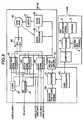
- FIG. 9 shows an IC card 1 having guarantee data storage 54 and a PC 7 to which the IC card 1 is connected.
- the PC 7 is similar to the one shown in FIG. 1.
- the guarantee data storage 54 in the IC card 1 contains data corresponding to that which has been supplied on a written guarantee.
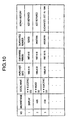
- FIG. 10 shows an example of data stored in the guarantee data storage 54.
- the guarantee data storage 54 stores the name of a component, supplier name, purchase date, guarantee period, guarantee number, repair history data, and so forth, for each component of the PC 7. This data is written into the IC card, for example, by the PC store when the PC is purchased or by the service center when the PC is repaired.
- the guarantee data stored in the guarantee data storage 54 is also sent to the service center.
- the service center terminal 21 compares the received guarantee data with the data stored in the customer information management unit 25 to check the guarantee period and so forth.
- the guarantee data storage 54 if provided in the IC card, allows guarantee data to be sent over the communication line, making it possible to check whether the guarantee is still valid or whether the repair service should be provided free of charge.
- an IC card stores information on the material and the disposal method of each part of an electrical appliance for effective disposal and re-cycling.
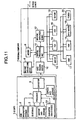
- FIG. 11 shows an IC card 1 having disposal data storage 55 and the PC 7 to which the IC card 1 is connected.
- the disposal data storage 55 contains disposal data describing the materials and disposal method of each part of the PC. This data is previously written by the PC manufacturer or vendor.
- the user wants to dispose of the PC, the user sends the disposal data to the municipal office or a disposal services company using the modem 9 in the PC 7 (or the modem in the telephone line terminal).
- the municipal office or the disposal services company calculates the disposal charge based on the received disposal data and sends back the calculated disposal charge and method (e.g. collection date) to the user. If the disposal charge is acceptable, the user pays the charge using sum information stored in the IC card.
- the Municipal office or the disposal services company When the municipal office or the disposal services company acknowledges the payment, it sends disposal permission data which certifies that the appropriate disposal charge was paid to the user.
- the disposal permission data sent to the user is stored in the disposal data storage 55.
- a junk dealer visits the user at a later date to collect the PC, the user gives the IC card 1 containing the disposal permission data to the junk dealer. Then, the junk dealer checks using a portable terminal, that the IC card 1 contains the disposal permission data and then collects the PC. A sequence of these processes makes disposal and collection more efficient.
- the disposal services company which gets the information about the materials of the parts and the disposal method in advance can perform disposal and recycling more smoothly.
- the machine data storage 4 stores information on the software contained in the machine. This information includes software version information and user registration numbers.
- the software contained in the machine include the programs stored in the EEPROM of the machine and the programs installed on the HDD. Information such as software version information and user registration numbers are written, for example, by the software development company or software vendor.
- Version information stored in the IC card which is sent to the service center via the communication line, is useful in calculating program upgrading charges or in identifying data necessary for software upgrading.
- a user registration number or ID number stored in the IC card which is sent to the service center via the communication line, allows the user to be identified as a valid user. Identifying the user using data stored in the IC card ensures security. Sum information stored in the IC card allows the charge to be paid immediately, thus making the payment of the charge for upgrading the software easier.
- FIG. 12 is a flowchart showing user-side processing and service center processing when the software upgrade service is provided.
- the user who wishes to upgrade the software accesses the service center using the modem (S301).
- the software version information is sent from the user side (S302).
- the service center checks the received version information (S303), calculates the charge required for software upgrading, and returns the result to the user (S304).
- the user determines whether to upgrade the software based on the estimated result displayed on the display (S305).
- the balance stored in the IC card is read (S306) to check if the user is able to pay the upgrading charge.
- the balance is compared with the required sum (S307). If it is found that the user is able to pay the charge as the result of comparison (S307, Y), the required sum information is sent to the service center and is stored in the sum information storage 31 in the IC card 28 of the service center (S309).
- the sales data stored in the sum information management unit 26 of the service center is updated (S310). After checking that the required sum is paid, the service center sends software upgrading data to the user (S311).
- this embodiment enables the programs stored in the machine's built-in ROM or the software products installed in the PC to be upgraded easily.
- the present invention may also be applied to a home video game system. For example, with the progress status data or the scores stored in the IC card, a player accesses the service center periodically to determine a ranking among the game participants or the winner of the game. In this case, game fees may also be paid using the IC card.
- the present invention is not limited to those described above.
- data is sent to, or received from, the service center over a telephone line in the above embodiments
- the communication method of the present invention is not limited to the telephone line. Any type of wire or wireless communication method capable of sending and receiving data may be used.
Landscapes
- General Physics & Mathematics (AREA)
- Physics & Mathematics (AREA)
- Engineering & Computer Science (AREA)
- Business, Economics & Management (AREA)
- General Business, Economics & Management (AREA)
- Computer Networks & Wireless Communication (AREA)
- Accounting & Taxation (AREA)
- Strategic Management (AREA)
- Microelectronics & Electronic Packaging (AREA)
- Theoretical Computer Science (AREA)
- Management, Administration, Business Operations System, And Electronic Commerce (AREA)
- Financial Or Insurance-Related Operations Such As Payment And Settlement (AREA)
- Control Of Vending Devices And Auxiliary Devices For Vending Devices (AREA)
- Telephonic Communication Services (AREA)
- Credit Cards Or The Like (AREA)
- Debugging And Monitoring (AREA)
Description
- The present invention relates to a system to provide services such as repair charge estimation and software upgrading with the use of an IC card containing data on electronic money and on the internal status of machines including PCs and household electrical appliances. The invention also relates to an IC card used in such a system.
- When a personal computer or household electrical appliance fails, the user normally takes it to an electrical appliances store or a manufacturer's service center to ask for an estimate of repair charges. In this case, the user must bring the failed computer or appliance to the store or the center himself, or ask a transportation company to transport it. This is very troublesome. In addition, as electrical appliances have become more and more sophisticated recently, it sometimes takes a long time to find the cause of a failure or to make an estimate of repair charges.
- On the other hand, the introduction of an electronic purse system using an IC card, as described in Japanese Patent Publication Kokai JP-A No. Hei 3-92966, is now under study. This system utilizes an IC card which contains memory, into which information on a specified amount of money is stored. At the time of payment, the required amount data read from the IC card is transmitted, to complete a transaction without using money. The IC card used with this system can store not only electronic money data but various other types of data.
- It is known in the art to collect internal data of a machine, e.g. operating data or malfunction data and to store such data on a chip card for further use or evaluation. Examples of such arrangements are described in EP-A-0 387 972 "Method to operate an automatic device" or in EP-A-0 495 104 "Managing system for construction machines".
- It is an object of the present invention to provide a labor-saving and time-saving system which uses an IC card containing sum (cash value) information for use in services such as an estimate of repair charges.
- This object is achieved by a system for remote maintenance in accordance with
claim 1 and an IC card in accordance withclaims - The system according to the present invention is used to acquire data on the internal status of a machine, and is used with an IC card having storage. This machine data acquisition system comprises an IC card accepting module for accepting the IC card; a machine data acquisition module for acquiring data on the internal status of the connected machine; and an IC card writing module for writing the data on the internal status of the machine acquired by the machine data acquisition module into the storage in the IC card.
- A machine according to the present invention is used with an IC card having storage. This machine comprises an IC card accepting module for accepting the IC card; a machine data acquisition module for acquiring data on the internal status of the machine; a writing module for writing the machine data acquired by the machine data acquisition module into the storage in the IC card; and a data sending module for sending data stored in the IC card over a communication line.
- In the data acquisition system and the machine described above, machine-specific data may be stored previously in the storage in the UC card. This machine-specific data, as well as the acquired machine data, is sent over the communication line. Alternatively, only the machine-specific data may be sent. For example, the machine-specific data can be machine guarantee data or machine disposal information (e.g. disposal method, parts materials).
- A machine data collection method of collecting data on the internal status of a machine according to the present invention comprises the steps of acquiring data on the internal status of the machine; recording the acquired data in an IC card; sending the machine status data over a communication line; and receiving the sent data.
- A terminal according to the present invention is used with an IC card containing sum information and machine data. This terminal comprises an IC card accepting module for accepting the IC card; a data reading module for reading data stored on the IC card; and a data sending module for sending, over a communication line, data read by the data reading module.
- An IC card according to the present invention is used with a machine whose internal status data is to be acquired. This IC card comprises sum information storage for storing sum information; and machine data storage for storing internal data on the machine. Another form of IC card according to the present invention comprises sum information storage for storing sum information; and disposal data storage for storing disposal data required when a machine is disposed of.
- A data processing system according to the present invention is used with an IC card on which sum information and software information are recorded. This data processing system comprises a storage module for storing a software; an IC card accepting module for accepting the IC card; a data reading module for reading data from the IC card; a sending module for sending, over a communication line, the software information read by the data reading module; a receiving module for receiving charge information required for upgrading the software, the charge information being sent in response to the sent software information; and a sum information sending module for sending sum information from the IC card, the sum information corresponding to the received charge information.
- A software upgrading method according to the present invention uses an IC card on which sum information and software information are recorded. This method first reads the software information and sends the read information over a communication line. Next, the method receives the information that was sent over a communication line and calculates a charge required for upgrading the software based on the received information.
Next, the method sends the calculated charge information. Then, the method receives the charge information required for upgrading the software; and sends sum information from the IC card, the sum information corresponding to the received charge information. -
- FIG. 1 is a diagram showing a first embodiment in which the present invention is applied to the error diagnosis of a personal computer.
- FIG. 2 shows an example of data stored in machine data storage.
- FIG. 3 is a diagram showing a second embodiment in which the present invention is applied to the error diagnosis of a personal computer.
- FIG. 4 is a diagram showing how data is transferred between a personal computer and a service center.
- FIG. 5 is a diagram showing how data is transferred between a telephone line terminal and a service center.
- FIG. 6 is a flowchart showing an example of operation in which a personal computer accesses a service center.
- FIG. 7 is a flowchart showing another example of operation in which a personal computer accesses a service center.
- FIG. 8 is a diagram showing an embodiment in which the present invention is applied to the error diagnosis of a VCR.
- FIG. 9 is a diagram showing a third embodiment in which the present invention is applied to the error diagnosis of a personal computer.
- FIG. 10 shows an example of data stored in guarantee data storage.
- FIG. 11 is a diagram showing a fourth embodiment in which the present invention is applied to the error diagnosis of a personal computer.
- FIG. 12 is a flowchart showing an example of how software upgrading service is performed.
- The following describe some embodiments of the present invention with reference to the attached drawings.
- FIG. 1 is a diagram showing a system, one of the embodiments of the present invention, which diagnoses the status of the machines (component devices) of a personal computer. As shown in FIG. 1, this system includes an
IC card 1 and a personal computer (hereafter called a PC) 7. - The
IC card 1 comprises sum (cash value)information storage 2,ID storage 3,machine data storage 4, aprocessor 5, and aconnector 6. Theprocessor 5 is connected to thesum information storage 2,ID storage 3,machine data storage 4, andconnector 6. - The PC 7 comprises a machine
data holding device 8, amodem 9, an IC card reader/writer 10, acentral processing unit 11, a machinedata check device 12, adisplay 13, a floppy disk drive (hereafter called an FDD) 14, a hard disk drive (hereafter called an HDD) 15, a CD-ROM drive (hereafter called a CD-ROM) 16, aRAM 17, aROM 18, aninput device 19, and a PCMCIA card interface (hereafter called PCMCIA) 20. Thecentral processing unit 11 is connected to the machinedata holding device 8,modem 9, IC card reader/writer 10, machinedata check device 12,display 13, FDD 14,HDD 15, CD-ROM 16,RAM 17,ROM 18,input device 19, and PCMCIA 20. The machinedata check device 12 is connected to themodem 9,central processing unit 11,display 13, FDD 14,HDD 15, CD-ROM 16,RAM 17,ROM 18,input device 19, and PCMCIA 20. As shown in FIG. 1, thecentral processing unit 11 and the machinedata check device 12 are connected to thedisplay 13, FDD 14,HDD 15, CD-ROM 16,RAM 17,ROM 18,input device 19, and PCMCIA 20 using one bus. However, they may be connected using separate signal lines. - When the user turns off the power of the
PC 7, the machine data checkdevice 12 reads the status of each machine and stores the machine status data in the machinedata holding device 8. The machine data checkdevice 12 may be designed so that it reads the status of each machine not only at the time of power-off but at a regular interval to store the status data into the machinedata holding device 8. This keeps the machine data in the machinedata holding device 8 up to date. - When the
IC card 1 is connected to thePC 7 in this situation, thecentral processing unit 11 is informed of the connection of the IC card. Upon detecting the connection, thecentral processing unit 11 reads machine data from the machinedata holding device 8 of thePC 7 and, via the card reader/writer 10, writes the machine data into themachine data storage 4 in theIC card 1. The system may also be designed so that, when theIC card 1 is already connected to thePC 7, machine data is stored not only into the machinedata holding device 8 but also into themachine data storage 4 in theIC card 1. - FIG. 2 shows an example of data stored in the
machine data storage 4 in theIC card 1. As shown in FIG. 2, themachine data storage 4 contains the name, machine specifications, model number, product number, and status (usage period, error status, error code, etc.) of each machine (component device) of thePC 7. The name, specifications, model number, and product number are written into themachine data storage 4 in the IC card, for example, by a PC store. When a user buys a PC, the IC card containing such data comes with the PC. The "machine status" field in themachine data storage 4 holds the machine data on each machine read by the machine data checkdevice 12. - FIG. 3 shows an embodiment in which a
PC 7 does not have a machinedata holding device 8. ThePC 7 shown in FIG. 3 is similar to thePC 7 shown in FIG. 1 except that the former does not have the machinedata holding device 8. In this embodiment, anIC card 1 is constantly connected to thePC 7, and machine data read by a machinedata check device 12 is stored inmachine data storage 4 in theIC card 1. - Although the
central processing unit 11 and the machine data checkdevice 12 are separate in the above embodiments, these two may be combined into one. - FIG. 4 shows an example in which machine data is sent from the
PC 7 to aservice center terminal 21 when the PC fails. As shown in FIG. 4, theservice center terminal 21 comprises amodem 22, aprocessor 23, a machinedata management unit 24, a customerinformation management unit 25, a suminformation management unit 26, and a card reader/writer 27. AnIC card 28 is also connected to theservice center terminal 21. In this embodiment, sum information having monetary values is transferred between IC cards. TheIC card 28 comprises aconnector 29, aprocessor 30,sum information storage 31, andID storage 32. - When the
PC 7 is malfunctioning, the user of thePC 7 accesses theservice center terminal 21 installed in the service center, via themodem 9. When a connection is established between the modems, thePC 7 sends machine data to the service center via themodem 9. Upon receiving the machine data, theservice center terminal 21 compares it with machine data stored in the machinedata management unit 24 to identify the location and the cause of the error generated in the personal computer. Based on the comparison result, theservice center terminal 21 estimates the repair charges and the required repair time, and sends the estimated result to themodem 9 at the user site over a telephone line. The estimated result sent from the service center over the telephone line is received by themodem 9 at the user site and displayed on the display connected to thePC 7. The user checks the estimated result and determines whether to ask for repair. - Depending upon the error status of the
PC 7, it may be impossible to access the service center via themodem 9 in thePC 7. In that case, machine data is sent to the service center with the use of a telephone line terminal and an IC card containing therein the machine data. - FIG. 5 shows an example in which a telephone line terminal is used. As shown in FIG. 5, a
telephone line terminal 33 comprises aninput device 34, adisplay 35, aprocessor 36, amodem 37, and an IC card reader/writer 38. Theprocessor 36 is connected to theinput device 34,display 35,modem 37, and the card reader/writer 38. - When the
IC card 1 is inserted into thetelephone line terminal 33, machine data stored in themachine data storage 4 in theIC card 1 is read by thetelephone line terminal 33 and is sent via the telephone line to theservice center terminal 21 installed in the service center. Thetelephone line terminal 33 can be implemented by adding the machine data sending function, which sends machine data stored in the IC card, to a telephone capable of sending electronic money or to a telephone adapter connected to a standard telephone. - FIG. 6 is a flowchart showing processing performed at a PC user side and the service center when the user's PC fails and the user receives the repair charges estimate service. As shown in FIG. 6, when the PC fails, the user first accesses the
service center terminal 21 installed in the service center via themodem 9 in the PC 7 (or themodem 37 in the telephone line terminal 33) (S101). When a connection is established between the two modems, machine data stored in themachine data storage 4 in theIC card 1 is sent to the service center via the modem 9 (or modem 37) (S102). Upon receiving the machine data, theservice center terminal 21 compares it with data stored in the machinedata management unit 24 to identify the location and the cause of the error generated in the PC (S103). Based on the comparison result, theservice center terminal 21 estimates the required repair charges and repair time, and sends the estimated result to the user over the telephone line (S104). The estimated result sent from the service center is displayed on the display of thePC 7 or thetelephone line terminal 33. The user checks the estimated result and determines whether to ask for repair (S105). If the estimated result is acceptable, the user requests repair of the PC. - In this embodiment, the user who requests repair of the PC is able to immediately pay the estimated charge fully or partially. When the user requests to pay, the balance (sum information) stored in the IC card is read (S106) and is compared with the required sum (S107) to check if it is possible to pay the sum with the IC card. If the balance is equal to or larger than the sum, the specified sum is sent to the service center and is stored in the
sum information storage 31 in theIC card 28 connected to the service center terminal 21 (S109). At the same time, the sales data stored in the suminformation management unit 26 in theservice center terminal 21 is updated (S110). - Then, a repair instruction is sent from the service center to the user (S111) and the processing ends (S112).
- On the other hand, if the balance is smaller than the sum, a message indicating the insufficient-balance appears on the user's display (S108) and processing ends (S112).
- As described above, the system in this embodiment sends machine data indicating the PC status to the service center over the telephone line. Therefore, when the PC fails, the system eliminates the need for the user to send the PC unit to the electrical appliance store or manufacturer's service center, thus saving the efforts and time required to estimate the repair charges.
- FIG. 7 is a flowchart showing another embodiment of this invention. This flowchart is also composed of the steps performed at the user side and the service center when the user's PC fails and the user asks the service center to estimate the repair charge. This flowchart differs from the flowchart show in FIG. 6 in that, before machine data is sent to the service center, the ID number stored in the IC card is sent to allow the service center to check if the requesting user is a valid user.
- As shown in FIG. 7, when the PC fails, the user first accesses the
service center terminal 21 installed in the service center via themodem 9 in the PC 7 (or themodem 37 in the telephone line terminal 33) (S201). When a connection is established between the modems, the modem 9 (or the modem 37) sends the ID number stored in theID storage 3 of theIC card 1 to the service center (S202). Upon receiving the ID number, the service center terminal checks if the received ID number is registered (S203). If the ID number is registered, the service center sends information indicating that the user may proceed with the processing. In this case, the steps S205 - S211 are preformed. Steps 205 to S214 are the same as steps S102 - S111 in FIG. 6. - On the other hand, if the ID number is not registered, the service center sends information indicating that it cannot proceed with the processing. Upon receiving the information, the system at the user site displays a message on the display indicating that the ID number is not registered (S204) and ends processing (S215).
- By performing the above processing, this embodiment allows only the registered users to receive the service.
- In the above description, the present invention is applied to personal computers. The present invention also finds applications in household electrical appliances such as a TV or a VCR as described below.
- FIG. 8 shows a videocassette recorder (VCR) according to the present invention. As shown in FIG. 8, a
VCR 39 comprises atuner 40, anRF converter 41, abrightness signal processor 42, acolor signal processor 43, anaudio signal processor 44, aswitch 45, avideo head 46, amotor 47, aservo processor 48, amotor driver 49, a machinedata holding unit 50, aprocessor 51, amachine status checker 52, and an IC card reader/writer 53. - When data is recorded, video signals and audio signals from an antenna input terminal, a video input terminal, and an audio input terminal are modulated by the
brightness signal processor 42,color signal processor 43, andaudio signal processor 44 and are combined. The combined signals are sent to thevideo head 46 via theswitch 45 for recording by thevideo head 46 on magnetic tape. - On the other hand, when data is played back, the signal read by the
video head 46 is frequency-separated, modulated by thebrightness signal processor 42,color signal processor 43, andaudio signal processor 44, and then output from an RF output terminal, a video output terminal, and an audio output terminal. Thevideo head 46 is turned by themotor 47. Thevideo head 46 andmotor 47 are controlled by theservo processor 48 and themotor driver 49. - As shown in FIG. 8, the
tuner 40,RF converter 41,brightness signal processor 42,color signal processor 43,audio signal processor 44,servo processor 48, andmotor driver 49 are connected to themachine status checker 52. Themachine status checker 52 reads operation status data on each machine (component unit) at a predetermined timing and stores the data in the machinedata holding unit 50 as machine data. In this situation, inserting theIC card 1 into theVCR 39 causes machine data to be copied from the machinedata holding unit 50 to themachine data storage 4 in the IC card. - After the machine data has been read from the
VCR 39 using theIC card 1 as described above, theIC card 1 is connected to thetelephone line terminal 33 such as the one shown in FIG. 5. Thetelephone line terminal 33 reads machine data from theIC card 1 and sends it to the service center over the telephone line. Based on the received machine data, the service center estimates the required repair charge and the repair time, and sends the estimated result information to thetelephone line terminal 33 on the user site via the telephone line. Upon receiving the information from theservice center terminal 21, thetelephone line terminal 33 displays it on thedisplay 35. - In the embodiment shown in FIG. 8, the
processor 51 and themachine status checker 52 are separate. However, theprocessor 51 may carry out all processing. - As described above, the status of the components of a failing household electrical appliance is read, stored in the IC card, and sent to the service center over the telephone line. Therefore, the need for the user to send the failing household electrical appliance to the manufacturer's service center is eliminated, thus significantly saving the efforts and time required to estimate the repair charges and the required repair time.
- The present invention may also be applied to products other than PCs and household electrical appliances. For example, the IC card, if installed on a car, is able to get status data on the parts of the car. When the car needs repairing, status data on the parts of the car stored in the IC card can be used for identifying the cause of a failure or estimating the repair charge. In addition, the repair charge may be paid using sum information stored in the IC card.
- Next, another embodiment in which guarantee (warranty) data is managed with the use of an IC card is described. In this embodiment, guarantee data which has been supplied on paper is stored in the IC card.
- FIG. 9 shows an
IC card 1 havingguarantee data storage 54 and aPC 7 to which theIC card 1 is connected. ThePC 7 is similar to the one shown in FIG. 1. Theguarantee data storage 54 in theIC card 1 contains data corresponding to that which has been supplied on a written guarantee. - FIG. 10 shows an example of data stored in the
guarantee data storage 54. As shown in FIG. 10, theguarantee data storage 54 stores the name of a component, supplier name, purchase date, guarantee period, guarantee number, repair history data, and so forth, for each component of thePC 7. This data is written into the IC card, for example, by the PC store when the PC is purchased or by the service center when the PC is repaired. - When machine data is sent to the service center (for example, in S102 of FIG. 6), the guarantee data stored in the
guarantee data storage 54 is also sent to the service center. Theservice center terminal 21 compares the received guarantee data with the data stored in the customerinformation management unit 25 to check the guarantee period and so forth. - Thus, the
guarantee data storage 54, if provided in the IC card, allows guarantee data to be sent over the communication line, making it possible to check whether the guarantee is still valid or whether the repair service should be provided free of charge. - Next, still another embodiment will be described. Recently, various regulations are established concerning the disposal of household electrical appliances in order to protect the environment. For example, electrical appliances must be classified by material for re-cycling before disposal or appropriate disposal methods must be used. In this embodiment, an IC card stores information on the material and the disposal method of each part of an electrical appliance for effective disposal and re-cycling.
- FIG. 11 shows an
IC card 1 havingdisposal data storage 55 and thePC 7 to which theIC card 1 is connected. Thedisposal data storage 55 contains disposal data describing the materials and disposal method of each part of the PC. This data is previously written by the PC manufacturer or vendor. When the PC user wants to dispose of the PC, the user sends the disposal data to the municipal office or a disposal services company using themodem 9 in the PC 7 (or the modem in the telephone line terminal). Upon receiving the disposal data, the municipal office or the disposal services company calculates the disposal charge based on the received disposal data and sends back the calculated disposal charge and method (e.g. collection date) to the user. If the disposal charge is acceptable, the user pays the charge using sum information stored in the IC card. When the municipal office or the disposal services company acknowledges the payment, it sends disposal permission data which certifies that the appropriate disposal charge was paid to the user. The disposal permission data sent to the user is stored in thedisposal data storage 55. When a junk dealer visits the user at a later date to collect the PC, the user gives theIC card 1 containing the disposal permission data to the junk dealer. Then, the junk dealer checks using a portable terminal, that theIC card 1 contains the disposal permission data and then collects the PC. A sequence of these processes makes disposal and collection more efficient. In addition, the disposal services company which gets the information about the materials of the parts and the disposal method in advance can perform disposal and recycling more smoothly. - Software upgrade service, another embodiment of the present invention, is described below. In this embodiment, the
machine data storage 4 stores information on the software contained in the machine. This information includes software version information and user registration numbers. The software contained in the machine include the programs stored in the EEPROM of the machine and the programs installed on the HDD. Information such as software version information and user registration numbers are written, for example, by the software development company or software vendor. - Version information stored in the IC card, which is sent to the service center via the communication line, is useful in calculating program upgrading charges or in identifying data necessary for software upgrading. A user registration number or ID number stored in the IC card, which is sent to the service center via the communication line, allows the user to be identified as a valid user. Identifying the user using data stored in the IC card ensures security. Sum information stored in the IC card allows the charge to be paid immediately, thus making the payment of the charge for upgrading the software easier.
- FIG. 12 is a flowchart showing user-side processing and service center processing when the software upgrade service is provided. As shown in FIG. 12, the user who wishes to upgrade the software accesses the service center using the modem (S301). When communication with the service center is established, the software version information is sent from the user side (S302). The service center checks the received version information (S303), calculates the charge required for software upgrading, and returns the result to the user (S304).
- The user determines whether to upgrade the software based on the estimated result displayed on the display (S305). When the user decides to upgrade the software, the balance stored in the IC card is read (S306) to check if the user is able to pay the upgrading charge. The balance is compared with the required sum (S307). If it is found that the user is able to pay the charge as the result of comparison (S307, Y), the required sum information is sent to the service center and is stored in the
sum information storage 31 in theIC card 28 of the service center (S309). At the same time, the sales data stored in the suminformation management unit 26 of the service center is updated (S310). After checking that the required sum is paid, the service center sends software upgrading data to the user (S311). - On the other hand, if the balance is smaller than the sum (S307, N), a message indicating the insufficient-balance appears on the user's display (S308) and processing ends.
- As described above, this embodiment enables the programs stored in the machine's built-in ROM or the software products installed in the PC to be upgraded easily.
- Recently, as PC operations or machine setup procedures becomes more complicated, PCs are getting more and more difficult to use, especially for beginners. To cope with this problem, some software vendors provide paid user support services over the telephone. In such a case, if information stored in the PC or IC card, such as software version information or user registration numbers, is sent to the service center, the service center can determine, based on the received information, the service best suited for the user and give him appropriate advice efficiently. When the service center provides the user with this type of service, the charge for the service may be paid immediately using the sum information stored in the
IC card 1. - The present invention may also be applied to a home video game system. For example, with the progress status data or the scores stored in the IC card, a player accesses the service center periodically to determine a ranking among the game participants or the winner of the game. In this case, game fees may also be paid using the IC card.
- While the preferred forms of the present invention have been described, it is to be understood that the present invention is not limited to those described above. For example, although data is sent to, or received from, the service center over a telephone line in the above embodiments, the communication method of the present invention is not limited to the telephone line. Any type of wire or wireless communication method capable of sending and receiving data may be used.
Claims (6)
- A system for remote servicing of a machine, comprising:a machine (7) with data acquisition means (12) for acquiring machine data on an internal status of the machine;writing means (10) in the machine for writing the acquired machine data into the storage (4) of an IC card (1) in an IC accepting means;data sending means (9, 37) for sending acquired machine data in the storage of the IC card over a communication line;data receiving means (37) for receiving servicing information sent back in response to the sent machine data;accepting means (S 105) for accepting the performance of a servicing operation in accordance with the sent back information.
- The system according to claim 1, wherein said servicing information comprises a charge for performing the servicing operation and wherein said data sending means transfer an equivalent value from the sum information (2) stored in the storage of the IC card over the communication line, after the performance of the servicing operation has been accepted.
- The system according to claim 1 or 2, wherein machine-specific data in the storage of said IC card is sent by a telephone terminal (33) comprising reading means for said IC card, data sending means, said data receiving means and said accepting means.
- The system of claim 1 or 2, wherein said machine data are simultaneously stored in the storage of the IC card and a internal data storage (8) of the machine and wherein said machine data are sent from the internal data storage of said machine.
- An IC card for use in a system in accordance with one of the claims 1 to 4, comprising:a machine data storage (4) for storing internal data on the machine;a sum information storage (2) for storing information on money-worth values; anda guarantee data storage (54) for storing machine guarantee data.
- An IC card for use in a system in accordance with one of the claims 1 to 4, comprising:a sum information storage (2) for storing information on money-worth values; anda disposal data storage (55) for storing disposal data required when said machine is disposed of, the disposal data being indicative of a material andan appropriate disposal method of each part of said machine.
Applications Claiming Priority (3)
| Application Number | Priority Date | Filing Date | Title |
|---|---|---|---|
| JP15065397A JP3909115B2 (en) | 1997-06-09 | 1997-06-09 | Apparatus information acquisition apparatus and apparatus apparatus information collection method |
| JP15065397 | 1997-06-09 | ||
| JP150653/97 | 1997-06-09 |
Publications (3)
| Publication Number | Publication Date |
|---|---|
| EP0884701A2 EP0884701A2 (en) | 1998-12-16 |
| EP0884701A3 EP0884701A3 (en) | 2003-09-03 |
| EP0884701B1 true EP0884701B1 (en) | 2006-11-02 |
Family
ID=15501555
Family Applications (1)
| Application Number | Title | Priority Date | Filing Date |
|---|---|---|---|
| EP98109080A Expired - Lifetime EP0884701B1 (en) | 1997-06-09 | 1998-05-19 | Machine data acquisition system and method |
Country Status (10)
| Country | Link |
|---|---|
| US (1) | US6199755B1 (en) |
| EP (1) | EP0884701B1 (en) |
| JP (1) | JP3909115B2 (en) |
| KR (1) | KR100302932B1 (en) |
| CN (1) | CN1163852C (en) |
| DE (1) | DE69836296T2 (en) |
| ID (1) | ID20811A (en) |
| MY (1) | MY126570A (en) |
| SG (1) | SG70636A1 (en) |
| TW (1) | TW385412B (en) |
Families Citing this family (31)
| Publication number | Priority date | Publication date | Assignee | Title |
|---|---|---|---|---|
| US8156026B2 (en) | 2000-05-12 | 2012-04-10 | Nintendo of America Ltd. | Method and apparatus for enabling purchasers of products to obtain return information and to initiate product returns via an on-line network connection |
| US6145738A (en) * | 1997-02-06 | 2000-11-14 | Mr. Payroll Corporation | Method and apparatus for automatic check cashing |
| AU740352B2 (en) * | 1997-10-28 | 2001-11-01 | Reckitt Benckiser (Uk) Limited | Compressed gas propelled aerosol devices |
| US6901377B1 (en) * | 2000-01-07 | 2005-05-31 | General Electric Company | Methods and systems for aviation parts, information and services |
| JP2002109098A (en) * | 2000-10-04 | 2002-04-12 | Fujitsu Ltd | Product information management method and repair request method |
| EP1598714B1 (en) * | 2000-12-13 | 2016-09-28 | LG Electronics Inc. | Apparatus and method for remotely controlling household appliances |
| JP2002288364A (en) * | 2001-03-26 | 2002-10-04 | Nec Corp | Service providing system, its method and its program |
| JP2002352127A (en) * | 2001-05-22 | 2002-12-06 | Sharp Corp | Information communication device, service providing system, information communication method, information communication program, recording medium storing information communication program |
| JP2003114943A (en) * | 2001-10-04 | 2003-04-18 | Hitachi Mobile Co Ltd | Vehicle failure diagnosis device, vehicle data center and vehicle failure diagnosis system |
| JP4029928B2 (en) * | 2002-03-28 | 2008-01-09 | 日本アイ・ビー・エム株式会社 | Communication apparatus, device user registration method, and program |
| JP2004064289A (en) * | 2002-07-26 | 2004-02-26 | Ntt Docomo Inc | Communication terminal, software transmission server and IC card writing device compatible with multiple wireless communication systems |
| CN1685376A (en) * | 2002-07-31 | 2005-10-19 | 松下电器产业株式会社 | Electronic receipt information processing system and electronic equipment |
| JP2004188080A (en) * | 2002-12-13 | 2004-07-08 | Aruze Corp | Game device |
| WO2005069184A1 (en) * | 2004-01-19 | 2005-07-28 | Matsushita Electric Industrial Co., Ltd. | Customer management system |
| US7844507B2 (en) * | 2006-03-22 | 2010-11-30 | Laundry Locker, Inc. | Handling household tasks |
| ITRN20070007A1 (en) | 2007-02-08 | 2007-05-10 | Indesit Company Spa | PORTABLE TECHNICAL ASSISTANCE DEVICE FOR A HOUSEHOLD APPLIANCE |
| US8302024B2 (en) | 2009-04-02 | 2012-10-30 | Nintendo Of America Inc. | Systems and/or methods for paging control including selective paging element display according to a binary subdivision and/or a serial progressive display approach |
| US10296916B2 (en) | 2009-09-11 | 2019-05-21 | Maridee Joy Maraz | System and/or method for handling recalled product purchases and/or return/warranty requests |
| US8712856B2 (en) | 2010-04-12 | 2014-04-29 | Nintendo Of America Inc. | Systems and/or methods for determining item serial number structure and intelligence |
| JP5558394B2 (en) * | 2011-03-18 | 2014-07-23 | 株式会社東芝 | Communication medium, IC card, command execution method |
| JP2012226642A (en) * | 2011-04-21 | 2012-11-15 | Yamato Scale Co Ltd | Maintenance inspection system |
| US8799111B2 (en) | 2012-05-04 | 2014-08-05 | Nintendo Of America Inc. | Systems and/or methods for selling non-inventory items at point-of-sale (POS) locations |
| US8840031B2 (en) * | 2012-06-14 | 2014-09-23 | Infineon Technologies Ag | Smart card and a method for operating a smart card |
| US9377791B2 (en) | 2012-10-08 | 2016-06-28 | International Business Machines Corporation | Monitoring user position to determine a time for providing a specified state at a user premises |
| CN103093511B (en) * | 2012-12-13 | 2015-10-28 | 成都宇泰达科技有限公司 | A kind of smart mobile phone cruising inspection system based on NFC and method for inspecting |
| US12236735B2 (en) | 2014-10-02 | 2025-02-25 | Luxer Corporation | Automated storage area |
| US11625675B2 (en) | 2014-10-02 | 2023-04-11 | Luxer Corporation | Method and system for controlling a storage room |
| US10445687B2 (en) | 2014-10-02 | 2019-10-15 | Luxer Corporation | Method and system for implementing electronic storage areas |
| US12626554B2 (en) | 2014-10-02 | 2026-05-12 | Luxer Corporation | Method and system for controlling a storage room |
| US12175410B2 (en) | 2014-10-02 | 2024-12-24 | Luxer Corporation | Automated storage area |
| US10810537B2 (en) | 2014-10-02 | 2020-10-20 | Luxer Corporation | Method and system for implementing electronic storage areas |
Family Cites Families (20)
| Publication number | Priority date | Publication date | Assignee | Title |
|---|---|---|---|---|
| FR2554936B1 (en) * | 1983-11-10 | 1986-08-29 | Saulnier Dominique | ELECTRONIC LABEL INFORMATION EXCHANGE SYSTEM |
| JP2593844B2 (en) * | 1985-06-12 | 1997-03-26 | ソニー株式会社 | Electronics |
| US4928230A (en) * | 1987-03-23 | 1990-05-22 | Kabushiki Kaisha Toshiba | Automatic transacting apparatus |
| DE3909323A1 (en) * | 1989-03-17 | 1990-09-20 | Kluessendorf Ag | METHOD FOR OPERATING AN AUTOMATE |
| JP2754745B2 (en) * | 1989-06-15 | 1998-05-20 | 株式会社日立製作所 | Remote maintenance system for automatic teller machine |
| JP3184196B2 (en) | 1989-09-06 | 2001-07-09 | 株式会社富士通総研 | Electronic wallet system |
| US5250761A (en) * | 1989-10-02 | 1993-10-05 | Kabushiki Kaisha Komatsu Seisakusho | Managing system for construction vehicles |
| US5091713A (en) * | 1990-05-10 | 1992-02-25 | Universal Automated Systems, Inc. | Inventory, cash, security, and maintenance control apparatus and method for a plurality of remote vending machines |
| AU2574092A (en) * | 1991-10-03 | 1993-05-03 | Thomson Consumer Electronics S.A. | Method and apparatus for customizing a device with a smart card |
| JPH0620117A (en) | 1991-11-18 | 1994-01-28 | Matsushita Electric Ind Co Ltd | IC card |
| FR2685113B1 (en) * | 1991-12-17 | 1998-07-24 | Gemplus Card Int | PROCESS OF INTERVENTION ON A TERMINAL OF GOODS OR SERVICES. |
| US5742760A (en) * | 1992-05-12 | 1998-04-21 | Compaq Computer Corporation | Network packet switch using shared memory for repeating and bridging packets at media rate |
| KR950001556A (en) * | 1993-06-28 | 1995-01-03 | 조백제 | Prepaid IC card and how to avoid tampering with it |
| US5484993A (en) * | 1993-09-24 | 1996-01-16 | Tamura Electric Works, Ltd. | Card reader maintenance system |
| EP0803828B1 (en) | 1994-12-02 | 2004-10-27 | Hitachi, Ltd. | Electronic money recovering system |
| GB9426341D0 (en) * | 1994-12-29 | 1995-03-01 | At & T Global Inf Solution | A transaction terminal |
| DE29512330U1 (en) * | 1995-07-31 | 1995-09-28 | Siemens AG, 80333 München | Product data storage facility |
| KR0152230B1 (en) * | 1995-09-29 | 1998-11-02 | 양승택 | Apparatus and method for checking & acknowledging identity of subscriber in network |
| EP0775990A3 (en) | 1995-11-21 | 2000-08-23 | Hitachi, Ltd. | IC card automated transaction terminal and IC card used therein |
| JPH09150653A (en) | 1995-11-29 | 1997-06-10 | Tachi S Co Ltd | Seat height adjustment device |
-
1997
- 1997-06-09 JP JP15065397A patent/JP3909115B2/en not_active Expired - Fee Related
-
1998
- 1998-05-14 US US09/078,971 patent/US6199755B1/en not_active Expired - Lifetime
- 1998-05-14 TW TW087107463A patent/TW385412B/en not_active IP Right Cessation
- 1998-05-14 SG SG1998001060A patent/SG70636A1/en unknown
- 1998-05-19 DE DE69836296T patent/DE69836296T2/en not_active Expired - Lifetime
- 1998-05-19 EP EP98109080A patent/EP0884701B1/en not_active Expired - Lifetime
- 1998-06-02 MY MYPI98002454A patent/MY126570A/en unknown
- 1998-06-03 KR KR1019980020515A patent/KR100302932B1/en not_active Expired - Fee Related
- 1998-06-09 CN CNB981147755A patent/CN1163852C/en not_active Expired - Fee Related
- 1998-06-09 ID IDP980845A patent/ID20811A/en unknown
Also Published As
| Publication number | Publication date |
|---|---|
| CN1163852C (en) | 2004-08-25 |
| JPH10340301A (en) | 1998-12-22 |
| ID20811A (en) | 1999-03-11 |
| MY126570A (en) | 2006-10-31 |
| KR19990006618A (en) | 1999-01-25 |
| JP3909115B2 (en) | 2007-04-25 |
| CN1206163A (en) | 1999-01-27 |
| KR100302932B1 (en) | 2001-12-12 |
| EP0884701A2 (en) | 1998-12-16 |
| DE69836296T2 (en) | 2007-05-16 |
| EP0884701A3 (en) | 2003-09-03 |
| SG70636A1 (en) | 2000-02-22 |
| US6199755B1 (en) | 2001-03-13 |
| TW385412B (en) | 2000-03-21 |
| DE69836296D1 (en) | 2006-12-14 |
Similar Documents
| Publication | Publication Date | Title |
|---|---|---|
| US6199755B1 (en) | Machine data acquistion system and method | |
| US6452874B1 (en) | Recording medium having content identification section | |
| JP4074745B2 (en) | Content delivery return system | |
| JP3656856B2 (en) | Software acquisition method and data processing system for implementing the method | |
| US4951308A (en) | Automated vending of cellular hand-held telephones and cellular telephone services | |
| EP0919056B1 (en) | Storage medium having electronic circuit and computer system having the storage medium | |
| US5481463A (en) | Pay-per-use access to multiple electronic test capabilities | |
| US6694341B2 (en) | Computer system having predetermined data backup operations | |
| US6425522B1 (en) | IC card information processing system, and apparatus and cards for the same | |
| US5774651A (en) | False statement detection system | |
| JPH08241351A (en) | Selling method of data record,selling apparatus for communication software,memory device,chip card and selling system | |
| KR20010007655A (en) | An ic card which has many functions and a system | |
| JP4612252B2 (en) | Matching system for storage media for gaming facilities | |
| US20050209998A1 (en) | Information management apparatus, information management system and storing medium storing information management software | |
| JP2005125012A (en) | Game system | |
| KR20020029457A (en) | Lending/collecting system for information storing medium using on-line or wireless internet and lending/collecting method for information storing medium thereby | |
| JP2604204B2 (en) | Vending machine system | |
| JPS6323584B2 (en) | ||
| JPH10277251A (en) | Update system of recording media for lending playing media of amusement game | |
| JPH11102422A (en) | Reading device management system, reading device, and reading device management method | |
| JP2000029999A (en) | Memory card and memory card vending equipment | |
| US20010025270A1 (en) | Image searching and viewing system | |
| JP2900441B2 (en) | Prepaid card processing device | |
| JP2006085347A (en) | Sales management device and sales management method | |
| JP2003030459A (en) | Content recording performance totaling method, content usage fee distribution method, and device thereof |
Legal Events
| Date | Code | Title | Description |
|---|---|---|---|
| PUAI | Public reference made under article 153(3) epc to a published international application that has entered the european phase |
Free format text: ORIGINAL CODE: 0009012 |
|
| 17P | Request for examination filed |
Effective date: 19980519 |
|
| AK | Designated contracting states |
Kind code of ref document: A2 Designated state(s): AT BE CH CY DE DK ES FI FR GB GR IE IT LI LU MC NL PT SE |
|
| AX | Request for extension of the european patent |
Free format text: AL;LT;LV;MK;RO;SI |
|
| PUAL | Search report despatched |
Free format text: ORIGINAL CODE: 0009013 |
|
| AK | Designated contracting states |
Kind code of ref document: A3 Designated state(s): AT BE CH CY DE DK ES FI FR GB GR IE IT LI LU MC NL PT SE |
|
| AX | Request for extension of the european patent |
Extension state: AL LT LV MK RO SI |
|
| AKX | Designation fees paid |
Designated state(s): DE FR GB |
|
| GRAP | Despatch of communication of intention to grant a patent |
Free format text: ORIGINAL CODE: EPIDOSNIGR1 |
|
| GRAS | Grant fee paid |
Free format text: ORIGINAL CODE: EPIDOSNIGR3 |
|
| GRAA | (expected) grant |
Free format text: ORIGINAL CODE: 0009210 |
|
| AK | Designated contracting states |
Kind code of ref document: B1 Designated state(s): DE FR GB |
|
| REG | Reference to a national code |
Ref country code: GB Ref legal event code: FG4D |
|
| REF | Corresponds to: |
Ref document number: 69836296 Country of ref document: DE Date of ref document: 20061214 Kind code of ref document: P |
|
| ET | Fr: translation filed | ||
| PLBE | No opposition filed within time limit |
Free format text: ORIGINAL CODE: 0009261 |
|
| STAA | Information on the status of an ep patent application or granted ep patent |
Free format text: STATUS: NO OPPOSITION FILED WITHIN TIME LIMIT |
|
| 26N | No opposition filed |
Effective date: 20070803 |
|
| PGFP | Annual fee paid to national office [announced via postgrant information from national office to epo] |
Ref country code: DE Payment date: 20130515 Year of fee payment: 16 Ref country code: GB Payment date: 20130515 Year of fee payment: 16 |
|
| PGFP | Annual fee paid to national office [announced via postgrant information from national office to epo] |
Ref country code: FR Payment date: 20130531 Year of fee payment: 16 |
|
| REG | Reference to a national code |
Ref country code: DE Ref legal event code: R119 Ref document number: 69836296 Country of ref document: DE |
|
| GBPC | Gb: european patent ceased through non-payment of renewal fee |
Effective date: 20140519 |
|
| REG | Reference to a national code |
Ref country code: FR Ref legal event code: ST Effective date: 20150130 |
|
| REG | Reference to a national code |
Ref country code: DE Ref legal event code: R119 Ref document number: 69836296 Country of ref document: DE Effective date: 20141202 |
|
| PG25 | Lapsed in a contracting state [announced via postgrant information from national office to epo] |
Ref country code: DE Free format text: LAPSE BECAUSE OF NON-PAYMENT OF DUE FEES Effective date: 20141202 |
|
| PG25 | Lapsed in a contracting state [announced via postgrant information from national office to epo] |
Ref country code: GB Free format text: LAPSE BECAUSE OF NON-PAYMENT OF DUE FEES Effective date: 20140519 Ref country code: FR Free format text: LAPSE BECAUSE OF NON-PAYMENT OF DUE FEES Effective date: 20140602 |