EP0884486B1 - Electrohydraulic clamping device - Google Patents
Electrohydraulic clamping device Download PDFInfo
- Publication number
- EP0884486B1 EP0884486B1 EP98107636A EP98107636A EP0884486B1 EP 0884486 B1 EP0884486 B1 EP 0884486B1 EP 98107636 A EP98107636 A EP 98107636A EP 98107636 A EP98107636 A EP 98107636A EP 0884486 B1 EP0884486 B1 EP 0884486B1
- Authority
- EP
- European Patent Office
- Prior art keywords
- pressure
- valve
- switch
- piston
- pilot
- Prior art date
- Legal status (The legal status is an assumption and is not a legal conclusion. Google has not performed a legal analysis and makes no representation as to the accuracy of the status listed.)
- Expired - Lifetime
Links
Images
Classifications
-
- F—MECHANICAL ENGINEERING; LIGHTING; HEATING; WEAPONS; BLASTING
- F15—FLUID-PRESSURE ACTUATORS; HYDRAULICS OR PNEUMATICS IN GENERAL
- F15B—SYSTEMS ACTING BY MEANS OF FLUIDS IN GENERAL; FLUID-PRESSURE ACTUATORS, e.g. SERVOMOTORS; DETAILS OF FLUID-PRESSURE SYSTEMS, NOT OTHERWISE PROVIDED FOR
- F15B11/00—Servomotor systems without provision for follow-up action; Circuits therefor
- F15B11/02—Systems essentially incorporating special features for controlling the speed or actuating force of an output member
- F15B11/028—Systems essentially incorporating special features for controlling the speed or actuating force of an output member for controlling the actuating force
-
- B—PERFORMING OPERATIONS; TRANSPORTING
- B23—MACHINE TOOLS; METAL-WORKING NOT OTHERWISE PROVIDED FOR
- B23B—TURNING; BORING
- B23B31/00—Chucks; Expansion mandrels; Adaptations thereof for remote control
- B23B31/02—Chucks
- B23B31/24—Chucks characterised by features relating primarily to remote control of the gripping means
- B23B31/30—Chucks characterised by features relating primarily to remote control of the gripping means using fluid-pressure means in the chuck
- B23B31/302—Hydraulic equipment, e.g. pistons, valves, rotary joints
-
- B—PERFORMING OPERATIONS; TRANSPORTING
- B25—HAND TOOLS; PORTABLE POWER-DRIVEN TOOLS; MANIPULATORS
- B25B—TOOLS OR BENCH DEVICES NOT OTHERWISE PROVIDED FOR, FOR FASTENING, CONNECTING, DISENGAGING OR HOLDING
- B25B5/00—Clamps
- B25B5/06—Arrangements for positively actuating jaws
- B25B5/061—Arrangements for positively actuating jaws with fluid drive
-
- G—PHYSICS
- G05—CONTROLLING; REGULATING
- G05D—SYSTEMS FOR CONTROLLING OR REGULATING NON-ELECTRIC VARIABLES
- G05D16/00—Control of fluid pressure
- G05D16/20—Control of fluid pressure characterised by the use of electric means
- G05D16/2093—Control of fluid pressure characterised by the use of electric means with combination of electric and non-electric auxiliary power
- G05D16/2097—Control of fluid pressure characterised by the use of electric means with combination of electric and non-electric auxiliary power using pistons within the main valve
-
- F—MECHANICAL ENGINEERING; LIGHTING; HEATING; WEAPONS; BLASTING
- F15—FLUID-PRESSURE ACTUATORS; HYDRAULICS OR PNEUMATICS IN GENERAL
- F15B—SYSTEMS ACTING BY MEANS OF FLUIDS IN GENERAL; FLUID-PRESSURE ACTUATORS, e.g. SERVOMOTORS; DETAILS OF FLUID-PRESSURE SYSTEMS, NOT OTHERWISE PROVIDED FOR
- F15B2211/00—Circuits for servomotor systems
- F15B2211/20—Fluid pressure source, e.g. accumulator or variable axial piston pump
- F15B2211/205—Systems with pumps
- F15B2211/2053—Type of pump
- F15B2211/20538—Type of pump constant capacity
-
- F—MECHANICAL ENGINEERING; LIGHTING; HEATING; WEAPONS; BLASTING
- F15—FLUID-PRESSURE ACTUATORS; HYDRAULICS OR PNEUMATICS IN GENERAL
- F15B—SYSTEMS ACTING BY MEANS OF FLUIDS IN GENERAL; FLUID-PRESSURE ACTUATORS, e.g. SERVOMOTORS; DETAILS OF FLUID-PRESSURE SYSTEMS, NOT OTHERWISE PROVIDED FOR
- F15B2211/00—Circuits for servomotor systems
- F15B2211/20—Fluid pressure source, e.g. accumulator or variable axial piston pump
- F15B2211/205—Systems with pumps
- F15B2211/20576—Systems with pumps with multiple pumps
- F15B2211/20592—Combinations of pumps for supplying high and low pressure
-
- F—MECHANICAL ENGINEERING; LIGHTING; HEATING; WEAPONS; BLASTING
- F15—FLUID-PRESSURE ACTUATORS; HYDRAULICS OR PNEUMATICS IN GENERAL
- F15B—SYSTEMS ACTING BY MEANS OF FLUIDS IN GENERAL; FLUID-PRESSURE ACTUATORS, e.g. SERVOMOTORS; DETAILS OF FLUID-PRESSURE SYSTEMS, NOT OTHERWISE PROVIDED FOR
- F15B2211/00—Circuits for servomotor systems
- F15B2211/20—Fluid pressure source, e.g. accumulator or variable axial piston pump
- F15B2211/21—Systems with pressure sources other than pumps, e.g. with a pyrotechnical charge
- F15B2211/212—Systems with pressure sources other than pumps, e.g. with a pyrotechnical charge the pressure sources being accumulators
-
- F—MECHANICAL ENGINEERING; LIGHTING; HEATING; WEAPONS; BLASTING
- F15—FLUID-PRESSURE ACTUATORS; HYDRAULICS OR PNEUMATICS IN GENERAL
- F15B—SYSTEMS ACTING BY MEANS OF FLUIDS IN GENERAL; FLUID-PRESSURE ACTUATORS, e.g. SERVOMOTORS; DETAILS OF FLUID-PRESSURE SYSTEMS, NOT OTHERWISE PROVIDED FOR
- F15B2211/00—Circuits for servomotor systems
- F15B2211/30—Directional control
- F15B2211/305—Directional control characterised by the type of valves
- F15B2211/30505—Non-return valves, i.e. check valves
-
- F—MECHANICAL ENGINEERING; LIGHTING; HEATING; WEAPONS; BLASTING
- F15—FLUID-PRESSURE ACTUATORS; HYDRAULICS OR PNEUMATICS IN GENERAL
- F15B—SYSTEMS ACTING BY MEANS OF FLUIDS IN GENERAL; FLUID-PRESSURE ACTUATORS, e.g. SERVOMOTORS; DETAILS OF FLUID-PRESSURE SYSTEMS, NOT OTHERWISE PROVIDED FOR
- F15B2211/00—Circuits for servomotor systems
- F15B2211/30—Directional control
- F15B2211/305—Directional control characterised by the type of valves
- F15B2211/30525—Directional control valves, e.g. 4/3-directional control valve
-
- F—MECHANICAL ENGINEERING; LIGHTING; HEATING; WEAPONS; BLASTING
- F15—FLUID-PRESSURE ACTUATORS; HYDRAULICS OR PNEUMATICS IN GENERAL
- F15B—SYSTEMS ACTING BY MEANS OF FLUIDS IN GENERAL; FLUID-PRESSURE ACTUATORS, e.g. SERVOMOTORS; DETAILS OF FLUID-PRESSURE SYSTEMS, NOT OTHERWISE PROVIDED FOR
- F15B2211/00—Circuits for servomotor systems
- F15B2211/30—Directional control
- F15B2211/305—Directional control characterised by the type of valves
- F15B2211/3056—Assemblies of multiple valves
- F15B2211/30565—Assemblies of multiple valves having multiple valves for a single output member, e.g. for creating higher valve function by use of multiple valves like two 2/2-valves replacing a 5/3-valve
- F15B2211/3057—Assemblies of multiple valves having multiple valves for a single output member, e.g. for creating higher valve function by use of multiple valves like two 2/2-valves replacing a 5/3-valve having two valves, one for each port of a double-acting output member
-
- F—MECHANICAL ENGINEERING; LIGHTING; HEATING; WEAPONS; BLASTING
- F15—FLUID-PRESSURE ACTUATORS; HYDRAULICS OR PNEUMATICS IN GENERAL
- F15B—SYSTEMS ACTING BY MEANS OF FLUIDS IN GENERAL; FLUID-PRESSURE ACTUATORS, e.g. SERVOMOTORS; DETAILS OF FLUID-PRESSURE SYSTEMS, NOT OTHERWISE PROVIDED FOR
- F15B2211/00—Circuits for servomotor systems
- F15B2211/30—Directional control
- F15B2211/31—Directional control characterised by the positions of the valve element
- F15B2211/3105—Neutral or centre positions
- F15B2211/3111—Neutral or centre positions the pump port being closed in the centre position, e.g. so-called closed centre
-
- F—MECHANICAL ENGINEERING; LIGHTING; HEATING; WEAPONS; BLASTING
- F15—FLUID-PRESSURE ACTUATORS; HYDRAULICS OR PNEUMATICS IN GENERAL
- F15B—SYSTEMS ACTING BY MEANS OF FLUIDS IN GENERAL; FLUID-PRESSURE ACTUATORS, e.g. SERVOMOTORS; DETAILS OF FLUID-PRESSURE SYSTEMS, NOT OTHERWISE PROVIDED FOR
- F15B2211/00—Circuits for servomotor systems
- F15B2211/30—Directional control
- F15B2211/32—Directional control characterised by the type of actuation
- F15B2211/327—Directional control characterised by the type of actuation electrically or electronically
-
- F—MECHANICAL ENGINEERING; LIGHTING; HEATING; WEAPONS; BLASTING
- F15—FLUID-PRESSURE ACTUATORS; HYDRAULICS OR PNEUMATICS IN GENERAL
- F15B—SYSTEMS ACTING BY MEANS OF FLUIDS IN GENERAL; FLUID-PRESSURE ACTUATORS, e.g. SERVOMOTORS; DETAILS OF FLUID-PRESSURE SYSTEMS, NOT OTHERWISE PROVIDED FOR
- F15B2211/00—Circuits for servomotor systems
- F15B2211/40—Flow control
- F15B2211/405—Flow control characterised by the type of flow control means or valve
- F15B2211/40515—Flow control characterised by the type of flow control means or valve with variable throttles or orifices
-
- F—MECHANICAL ENGINEERING; LIGHTING; HEATING; WEAPONS; BLASTING
- F15—FLUID-PRESSURE ACTUATORS; HYDRAULICS OR PNEUMATICS IN GENERAL
- F15B—SYSTEMS ACTING BY MEANS OF FLUIDS IN GENERAL; FLUID-PRESSURE ACTUATORS, e.g. SERVOMOTORS; DETAILS OF FLUID-PRESSURE SYSTEMS, NOT OTHERWISE PROVIDED FOR
- F15B2211/00—Circuits for servomotor systems
- F15B2211/40—Flow control
- F15B2211/41—Flow control characterised by the positions of the valve element
- F15B2211/411—Flow control characterised by the positions of the valve element the positions being discrete
-
- F—MECHANICAL ENGINEERING; LIGHTING; HEATING; WEAPONS; BLASTING
- F15—FLUID-PRESSURE ACTUATORS; HYDRAULICS OR PNEUMATICS IN GENERAL
- F15B—SYSTEMS ACTING BY MEANS OF FLUIDS IN GENERAL; FLUID-PRESSURE ACTUATORS, e.g. SERVOMOTORS; DETAILS OF FLUID-PRESSURE SYSTEMS, NOT OTHERWISE PROVIDED FOR
- F15B2211/00—Circuits for servomotor systems
- F15B2211/40—Flow control
- F15B2211/415—Flow control characterised by the connections of the flow control means in the circuit
- F15B2211/41509—Flow control characterised by the connections of the flow control means in the circuit being connected to a pressure source and a directional control valve
-
- F—MECHANICAL ENGINEERING; LIGHTING; HEATING; WEAPONS; BLASTING
- F15—FLUID-PRESSURE ACTUATORS; HYDRAULICS OR PNEUMATICS IN GENERAL
- F15B—SYSTEMS ACTING BY MEANS OF FLUIDS IN GENERAL; FLUID-PRESSURE ACTUATORS, e.g. SERVOMOTORS; DETAILS OF FLUID-PRESSURE SYSTEMS, NOT OTHERWISE PROVIDED FOR
- F15B2211/00—Circuits for servomotor systems
- F15B2211/40—Flow control
- F15B2211/42—Flow control characterised by the type of actuation
- F15B2211/426—Flow control characterised by the type of actuation electrically or electronically
-
- F—MECHANICAL ENGINEERING; LIGHTING; HEATING; WEAPONS; BLASTING
- F15—FLUID-PRESSURE ACTUATORS; HYDRAULICS OR PNEUMATICS IN GENERAL
- F15B—SYSTEMS ACTING BY MEANS OF FLUIDS IN GENERAL; FLUID-PRESSURE ACTUATORS, e.g. SERVOMOTORS; DETAILS OF FLUID-PRESSURE SYSTEMS, NOT OTHERWISE PROVIDED FOR
- F15B2211/00—Circuits for servomotor systems
- F15B2211/40—Flow control
- F15B2211/45—Control of bleed-off flow, e.g. control of bypass flow to the return line
-
- F—MECHANICAL ENGINEERING; LIGHTING; HEATING; WEAPONS; BLASTING
- F15—FLUID-PRESSURE ACTUATORS; HYDRAULICS OR PNEUMATICS IN GENERAL
- F15B—SYSTEMS ACTING BY MEANS OF FLUIDS IN GENERAL; FLUID-PRESSURE ACTUATORS, e.g. SERVOMOTORS; DETAILS OF FLUID-PRESSURE SYSTEMS, NOT OTHERWISE PROVIDED FOR
- F15B2211/00—Circuits for servomotor systems
- F15B2211/50—Pressure control
- F15B2211/505—Pressure control characterised by the type of pressure control means
- F15B2211/50509—Pressure control characterised by the type of pressure control means the pressure control means controlling a pressure upstream of the pressure control means
- F15B2211/50536—Pressure control characterised by the type of pressure control means the pressure control means controlling a pressure upstream of the pressure control means using unloading valves controlling the supply pressure by diverting fluid to the return line
-
- F—MECHANICAL ENGINEERING; LIGHTING; HEATING; WEAPONS; BLASTING
- F15—FLUID-PRESSURE ACTUATORS; HYDRAULICS OR PNEUMATICS IN GENERAL
- F15B—SYSTEMS ACTING BY MEANS OF FLUIDS IN GENERAL; FLUID-PRESSURE ACTUATORS, e.g. SERVOMOTORS; DETAILS OF FLUID-PRESSURE SYSTEMS, NOT OTHERWISE PROVIDED FOR
- F15B2211/00—Circuits for servomotor systems
- F15B2211/50—Pressure control
- F15B2211/505—Pressure control characterised by the type of pressure control means
- F15B2211/50554—Pressure control characterised by the type of pressure control means the pressure control means controlling a pressure downstream of the pressure control means, e.g. pressure reducing valve
-
- F—MECHANICAL ENGINEERING; LIGHTING; HEATING; WEAPONS; BLASTING
- F15—FLUID-PRESSURE ACTUATORS; HYDRAULICS OR PNEUMATICS IN GENERAL
- F15B—SYSTEMS ACTING BY MEANS OF FLUIDS IN GENERAL; FLUID-PRESSURE ACTUATORS, e.g. SERVOMOTORS; DETAILS OF FLUID-PRESSURE SYSTEMS, NOT OTHERWISE PROVIDED FOR
- F15B2211/00—Circuits for servomotor systems
- F15B2211/50—Pressure control
- F15B2211/515—Pressure control characterised by the connections of the pressure control means in the circuit
- F15B2211/5151—Pressure control characterised by the connections of the pressure control means in the circuit being connected to a pressure source and a directional control valve
-
- F—MECHANICAL ENGINEERING; LIGHTING; HEATING; WEAPONS; BLASTING
- F15—FLUID-PRESSURE ACTUATORS; HYDRAULICS OR PNEUMATICS IN GENERAL
- F15B—SYSTEMS ACTING BY MEANS OF FLUIDS IN GENERAL; FLUID-PRESSURE ACTUATORS, e.g. SERVOMOTORS; DETAILS OF FLUID-PRESSURE SYSTEMS, NOT OTHERWISE PROVIDED FOR
- F15B2211/00—Circuits for servomotor systems
- F15B2211/50—Pressure control
- F15B2211/52—Pressure control characterised by the type of actuation
- F15B2211/528—Pressure control characterised by the type of actuation actuated by fluid pressure
-
- F—MECHANICAL ENGINEERING; LIGHTING; HEATING; WEAPONS; BLASTING
- F15—FLUID-PRESSURE ACTUATORS; HYDRAULICS OR PNEUMATICS IN GENERAL
- F15B—SYSTEMS ACTING BY MEANS OF FLUIDS IN GENERAL; FLUID-PRESSURE ACTUATORS, e.g. SERVOMOTORS; DETAILS OF FLUID-PRESSURE SYSTEMS, NOT OTHERWISE PROVIDED FOR
- F15B2211/00—Circuits for servomotor systems
- F15B2211/50—Pressure control
- F15B2211/55—Pressure control for limiting a pressure up to a maximum pressure, e.g. by using a pressure relief valve
-
- F—MECHANICAL ENGINEERING; LIGHTING; HEATING; WEAPONS; BLASTING
- F15—FLUID-PRESSURE ACTUATORS; HYDRAULICS OR PNEUMATICS IN GENERAL
- F15B—SYSTEMS ACTING BY MEANS OF FLUIDS IN GENERAL; FLUID-PRESSURE ACTUATORS, e.g. SERVOMOTORS; DETAILS OF FLUID-PRESSURE SYSTEMS, NOT OTHERWISE PROVIDED FOR
- F15B2211/00—Circuits for servomotor systems
- F15B2211/60—Circuit components or control therefor
- F15B2211/605—Load sensing circuits
- F15B2211/6051—Load sensing circuits having valve means between output member and the load sensing circuit
-
- F—MECHANICAL ENGINEERING; LIGHTING; HEATING; WEAPONS; BLASTING
- F15—FLUID-PRESSURE ACTUATORS; HYDRAULICS OR PNEUMATICS IN GENERAL
- F15B—SYSTEMS ACTING BY MEANS OF FLUIDS IN GENERAL; FLUID-PRESSURE ACTUATORS, e.g. SERVOMOTORS; DETAILS OF FLUID-PRESSURE SYSTEMS, NOT OTHERWISE PROVIDED FOR
- F15B2211/00—Circuits for servomotor systems
- F15B2211/60—Circuit components or control therefor
- F15B2211/615—Filtering means
-
- F—MECHANICAL ENGINEERING; LIGHTING; HEATING; WEAPONS; BLASTING
- F15—FLUID-PRESSURE ACTUATORS; HYDRAULICS OR PNEUMATICS IN GENERAL
- F15B—SYSTEMS ACTING BY MEANS OF FLUIDS IN GENERAL; FLUID-PRESSURE ACTUATORS, e.g. SERVOMOTORS; DETAILS OF FLUID-PRESSURE SYSTEMS, NOT OTHERWISE PROVIDED FOR
- F15B2211/00—Circuits for servomotor systems
- F15B2211/60—Circuit components or control therefor
- F15B2211/625—Accumulators
-
- F—MECHANICAL ENGINEERING; LIGHTING; HEATING; WEAPONS; BLASTING
- F15—FLUID-PRESSURE ACTUATORS; HYDRAULICS OR PNEUMATICS IN GENERAL
- F15B—SYSTEMS ACTING BY MEANS OF FLUIDS IN GENERAL; FLUID-PRESSURE ACTUATORS, e.g. SERVOMOTORS; DETAILS OF FLUID-PRESSURE SYSTEMS, NOT OTHERWISE PROVIDED FOR
- F15B2211/00—Circuits for servomotor systems
- F15B2211/60—Circuit components or control therefor
- F15B2211/63—Electronic controllers
- F15B2211/6303—Electronic controllers using input signals
- F15B2211/6306—Electronic controllers using input signals representing a pressure
- F15B2211/6309—Electronic controllers using input signals representing a pressure the pressure being a pressure source supply pressure
-
- F—MECHANICAL ENGINEERING; LIGHTING; HEATING; WEAPONS; BLASTING
- F15—FLUID-PRESSURE ACTUATORS; HYDRAULICS OR PNEUMATICS IN GENERAL
- F15B—SYSTEMS ACTING BY MEANS OF FLUIDS IN GENERAL; FLUID-PRESSURE ACTUATORS, e.g. SERVOMOTORS; DETAILS OF FLUID-PRESSURE SYSTEMS, NOT OTHERWISE PROVIDED FOR
- F15B2211/00—Circuits for servomotor systems
- F15B2211/60—Circuit components or control therefor
- F15B2211/63—Electronic controllers
- F15B2211/6303—Electronic controllers using input signals
- F15B2211/6306—Electronic controllers using input signals representing a pressure
- F15B2211/6313—Electronic controllers using input signals representing a pressure the pressure being a load pressure
-
- F—MECHANICAL ENGINEERING; LIGHTING; HEATING; WEAPONS; BLASTING
- F15—FLUID-PRESSURE ACTUATORS; HYDRAULICS OR PNEUMATICS IN GENERAL
- F15B—SYSTEMS ACTING BY MEANS OF FLUIDS IN GENERAL; FLUID-PRESSURE ACTUATORS, e.g. SERVOMOTORS; DETAILS OF FLUID-PRESSURE SYSTEMS, NOT OTHERWISE PROVIDED FOR
- F15B2211/00—Circuits for servomotor systems
- F15B2211/60—Circuit components or control therefor
- F15B2211/635—Circuits providing pilot pressure to pilot pressure-controlled fluid circuit elements
- F15B2211/6355—Circuits providing pilot pressure to pilot pressure-controlled fluid circuit elements having valve means
-
- F—MECHANICAL ENGINEERING; LIGHTING; HEATING; WEAPONS; BLASTING
- F15—FLUID-PRESSURE ACTUATORS; HYDRAULICS OR PNEUMATICS IN GENERAL
- F15B—SYSTEMS ACTING BY MEANS OF FLUIDS IN GENERAL; FLUID-PRESSURE ACTUATORS, e.g. SERVOMOTORS; DETAILS OF FLUID-PRESSURE SYSTEMS, NOT OTHERWISE PROVIDED FOR
- F15B2211/00—Circuits for servomotor systems
- F15B2211/70—Output members, e.g. hydraulic motors or cylinders or control therefor
- F15B2211/705—Output members, e.g. hydraulic motors or cylinders or control therefor characterised by the type of output members or actuators
- F15B2211/7051—Linear output members
- F15B2211/7052—Single-acting output members
-
- F—MECHANICAL ENGINEERING; LIGHTING; HEATING; WEAPONS; BLASTING
- F15—FLUID-PRESSURE ACTUATORS; HYDRAULICS OR PNEUMATICS IN GENERAL
- F15B—SYSTEMS ACTING BY MEANS OF FLUIDS IN GENERAL; FLUID-PRESSURE ACTUATORS, e.g. SERVOMOTORS; DETAILS OF FLUID-PRESSURE SYSTEMS, NOT OTHERWISE PROVIDED FOR
- F15B2211/00—Circuits for servomotor systems
- F15B2211/70—Output members, e.g. hydraulic motors or cylinders or control therefor
- F15B2211/705—Output members, e.g. hydraulic motors or cylinders or control therefor characterised by the type of output members or actuators
- F15B2211/7051—Linear output members
- F15B2211/7053—Double-acting output members
-
- F—MECHANICAL ENGINEERING; LIGHTING; HEATING; WEAPONS; BLASTING
- F15—FLUID-PRESSURE ACTUATORS; HYDRAULICS OR PNEUMATICS IN GENERAL
- F15B—SYSTEMS ACTING BY MEANS OF FLUIDS IN GENERAL; FLUID-PRESSURE ACTUATORS, e.g. SERVOMOTORS; DETAILS OF FLUID-PRESSURE SYSTEMS, NOT OTHERWISE PROVIDED FOR
- F15B2211/00—Circuits for servomotor systems
- F15B2211/70—Output members, e.g. hydraulic motors or cylinders or control therefor
- F15B2211/76—Control of force or torque of the output member
Definitions
- the invention relates to an electro-hydraulic clamping device according to the preamble of claim 1.
- Electro-hydraulic workpiece clamping devices are known from DE-A-44 23 541, DE-A-44 23 585 and DE-A-44 46 538.
- a proportional directional control valve is used during the lowering movement the upper press cheek as a safety valve.
- the spool of the directional control valve either through a limit switch or a position transmitter monitored in the form of a displacement sensor.
- the Invention based on the object to increase the operational reliability of construction to provide additional safety information for the control unit in a simple manner. In a structurally simple way, it should mean that the additional information from the function of an already existing component of the clamping device should be won.
- the safety valve which is present anyway, is to be maintained with it of the pilot pressure provided function used in combination with the Monitoring device for the higher-level control unit to derive the information, whether upstream of the safety valve and the clamping pressure adjustment valve properly hydraulic or electrical requirements for proper future surgical steps to be performed are available.
- the safety valve is at for setting the pilot pressure sufficient input pressure of the proportional pilot valve always open. The safety valve assumes its shut-off position if the pressure conditions change so that they do not interfere with the safety valve no longer guarantee that the pilot pressure is maintained.
- the control unit e.g. evaluate in connection with the clamping pressure message.
- the information is meaningful and reliable.
- the monitoring device can be structurally simple Arrange on or in the existing safety valve.
- An electrical switch used according to claim 2 in particular a microswitch, or a pressure switch or a proximity switch or proximity sensor, are inexpensive and structurally simple to combine with the safety valve without impair its normal function. Such switches also generate directly or with only minimal electronic effort for the higher-level control unit easily usable signals.
- the switching pressure is set in a structurally simple manner by tuning the area of action of the unlocking piston on the force of its return spring and, if applicable, the pressure surface of the valve element in the seat valve. With this tuning, however, it should be kept in mind that the safety valve is working properly switches to its shut-off position before the pilot pressure drops can.
- a pressure switch is used with its switching pressure the change in the unlocking pressure is coordinated. It is not a mechanical one Connection between the unlocking piston and the pressure switch required, see above that the function of the safety valve is not affected at all.
- the switch is expediently actuated by a plunger, on which the unlocking piston acts.
- the switching point of the switch can be precisely adjusted.
- an electro-hydraulic clamping device S in Fig. 1 in particular for a Workpiece or tool of a machine tool, the movements of a hydraulic motor W used for tensioning (for example a double-acting one Hydraulic cylinder) controlled, and the clamping pressure and, if necessary Return pressure monitors to a higher-level control unit, not shown, the machine tool (turning, drilling, milling machine or the like) operation steps display and report whether each operation step is carried out correctly or incorrectly or is prepared. For example, a proper application of the hydraulic motor W reported and whether the predetermined clamping pressure is reached or is not reached, regardless of the selected clamping pressure level. Furthermore, the higher-level control unit is informed when an electrical or a hydraulically critical condition has occurred.
- Two pumps P1 and P2 are provided as pressure sources, which are driven by a motor M to be driven.
- the pump P1 with a higher delivery rate is for a high system pressure designed, e.g. for an accumulator loading operation by means of a pressure accumulator 1 ', and connected to a pump line 1 and a return line 2.
- the Pump P2 with a smaller delivery rate is connected to its own pressure line 3 and via one Pressure limiter 4 connected to the return line 2, the pressure limiter 4 the pressure in the further pressure line 3 to a low value, e.g. 25 Bar limited.
- Both pumps P1, P2 can be constant feed pumps.
- An essential part of the tensioning device S is a hydraulic control device H with an adjusting device E for the clamping pressure.
- adjusting device E is a proportional pilot valve V and downstream of this a safety valve F arranged.
- the proportional pilot valve V is connected to the further pressure line 3 and with the safety valve F via two parallel control lines 14, 15 connected.
- the control line 14 is provided with a proportional pilot valve V can be varied depending on the energization of a proportional magnet P. Pilot pressure is applied while the control line 15 with an unlocking pressure for the safety valve F (in the embodiment shown, a hydraulic counter a spring 8 unlockable seat valve or ball check valve 7) acted upon is.
- the control line 14 sits downstream of the safety valve F as a control line 12 continues with a chamber 9 of the adjusting valve D and at the same time one side of a Differential pressure switching valve L is connected.
- the clamping pressure which can be regulated by means of the adjusting valve D is set.
- the In the embodiment shown, adjusting valve D is a regulating pressure reducing valve, which is connected to the pump line 1 and the return line 2.
- the Adjustment valve D is with a directional control valve J consisting of two seat valves connected, the two seat valves (for example 3/2-way valves) with the Hydraulic motor W are connected via consumer lines 5, 6.
- the clamping pressure is to be controlled by the adjusting valve D in Dependence on the pilot pressure in the control line 12 in accordance with the current supply of the proportional magnet P is set and held in its pressure value becomes.
- the differential pressure switching valve L is combined with a switch G, and structurally separate from the control valve D between the control line 12 and a control line 13 used, which branches off from the consumer line 5 and with one of Consumer pressure (clamping pressure) derived reference pressure is applied.
- the adjusting valve D has a control element 11 ', which is opposed by a control pressure is applied to a control spring 11.
- the control spring 11 is by a Actuating piston 10 loaded in the chamber 9 such that the effective spring force of the Control spring 11 depends directly on the pilot pressure in the control line 12. Will the Pilot pressure increased by changing the energization of the proportional magnet P, then the clamping pressure is raised accordingly, and vice versa.
- the hydraulic motor B like the directional control valve J designed as a seat valve, can be leakproof his. Leak tightness is at least largely present in the setting valve D, if the setting valve is in the shut-off position, as in the differential pressure switching valve L and in the safety valve in the shut-off position F. This means that the clamping pressure or reference pressure in the control line 13 as the pilot pressure in the control line 12 also remained unchanged for a considerable time become.
- the directional control valve directly to the pump line 1 is connected.
- the directional control valve J could be a 4/3-way control valve be with the middle position blocked, expediently in the seat valve design.
- a single pump could serve as a pressure source, whereby then it is advisable to add an additional pressure reducing valve upstream of the proportional pilot valve V. is provided to the input pressure of the proportional pilot valve V. to reduce the pressure level sufficient for the low pilot pressure.
- a pump could run the line to the proportional pilot valve V from the pump line 1 branch.
- the safety valve F has one from the control line 15 with the release pressure unlockable piston 16 which can be acted upon against the return spring 8.
- the monitoring device K uses the function of the shut-off valve F to derive the respective signal. For example contains the monitoring device K an electrical switch or microswitch 17th
- the safety valve F has no influence on the normal function of the tensioning device. i.e. the unlocking piston 16 holds the valve closing element 18 in the open position, so that the pilot pressure is unaffected in the control line 12. in case of a In the event of a power failure, the return spring 8 presses the unlocking piston 16 so quickly below that the valve closing element 18 blocks the backflow and the pilot pressure does not drop in the control line 12.
- the adjusting valve D maintains the clamping pressure.
- Switch G correctly reports "clamping pressure present or clamping pressure reached”. The pressures in the control lines 14 and 15 drop.
- the switch 17 speaks either on the falling pressure of the control line 15 or on the unlocking piston 16 at or on the changing position of the unlocking piston 16, and reports this the control unit C.
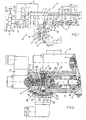
- Fig. 2 a detail of the clamping pressure adjusting device E is shown, which with the Proportional solenoid P equipped proportional pilot valve V that with this Safety valve F connected to the safety valve via the control lines 14 and 15 F the monitoring device K, adjacent to the safety valve F Adjustment valve D and above it the directional control valve J contains. From the adjustment valve D are the actuating piston 10 which can be acted upon via the control line 12 on the control spring 11 and the control element 11 'shown. Between the control channels 14 and 12, a valve seat 25 is provided in the safety valve F, which is designed as a ball Valve closing element 18 cooperates. Below the valve seat 25 the return spring 8 is arranged, which acts on the unlocking piston 16 downwards.
- the unlocking piston 16 projects into a chamber 19 to which the control line 15 connected.
- the chamber 19 is delimited by a closure element 24 which has a seal-provided passage for a plunger 20 that opens an actuator 21 of the switch 17, e.g. a microswitch is.
- the switch 17 is contained in a switch housing 22, which is in a holder 23 is optionally adjustable.
- the area of action of the unlocking piston 16 and the force of the return spring 8 (including the area of action of the valve closing element 18 in the valve seat 25) matched to one another such that the unlocking piston 16 at one predetermined pressure in the control line 15 or the control chamber 19 down is adjusted, e.g. still above the maximum adjustable pilot pressure in the control line 12 is, but below that normally in the further Pressure line 3 prevailing input pressure of the pilot valve V, preferably close to this input pressure. This ensures that the control pressure not unintentionally in the control line 12 in the event of a fault on the pilot side can be reduced.
- the unlocking piston 16 actuates the switch 17 via the plunger 20, for example as soon as the valve closing element 18 touches the valve seat 25 or is about to start, to put on the valve seat 25.
- the switching point of the switch 17 is at a predetermined one Position of the unlocking piston and indirectly to a certain pressure in the control chamber 19 set. If a pressure switch 17 'instead of the mechanical Switch 17 used, then the switching pressure of the pressure switch 17 'is not on the stroke of the unlocking piston 16, but only on the aforementioned pressure the control chamber 19 set.
- the signals present at the same time are in particular for the control unit C.
- "Tension pressure reached or tension pressure present” and the signal from the monitoring device K "Possible malfunction upstream of the safety valve” together important because the message signal "clamping pressure reached or clamping pressure present" control unit C alone could cause the logical conclusion that upstream there is no electrical and / or hydraulic fault in the safety valve and consequently, later processing steps or an adjustment of the clamping pressure are initiated could become.
- the signal "clamping pressure reached or Clamping pressure available "simultaneously with the signal” possible hydraulic and / or electrical fault upstream of the safety valve " then the control unit C draw the logical conclusion that no further processing steps are to be initiated or to issue a fault signal.
- the control unit C can draw the logical conclusion, first wait until the signal “clamping pressure reached or clamping pressure available "arrives and the signal” possible fault upstream of the safety valve " disappears, for example when adjusting the clamping pressure (lifting the Clamping pressure or lowering the clamping pressure) may be the case.
- This combination of signals can therefore be classified by the control unit C as initially uncritical become.
- the monitoring device K could also in the control line 15 or possibly even the control line 14 (with a pressure switch 17 ') can be arranged, or even upstream of the proportional pilot valve V.
- the main advantage of The solution shown in Fig. 2 is that the necessary for a meaningful signal Information in the control chamber 19 due to the function of the safety valve F occur, and the control chamber 19 anyway by mounting of the unlocking piston 16 enabling screw plug or a plug is closed is to be replaced only by the closure piece 24 or to attach the pressure switch must be removed. Further modifications to the concept of the safety valve are not required.
- the monitoring function that is important for operational safety can be realized with low costs and construction costs.
Abstract
Description
Die Erfindung betrifft eine elektrohydraulische Spannvorrichtung gemäß dem Oberbegriff
des Anspruchs 1.The invention relates to an electro-hydraulic clamping device according to the preamble
of
Für elektrohydraulische Spannvorrichtungen in Werkzeugmaschinen (Dreh-, Fräs-, Bohrmaschinen oder dgl.), die von einer übergeordneten, elektronischen Steuereinheit geführt werden, gelten außerordentlich hohe Sicherheitsanforderungen. Ehe die Steuereinheit einen Operationsschritt veranlaßt, benötigt sie möglichst viele Informationen, um den Operationsschritt ohne Schaden für die Werkzeugmaschine, die Spannvorrichtung, das Bedienungspersonal oder das Werkstück durchführen zu lassen. Elektrohydraulische Werkstück-Spannvorrichtungen sind bekannt aus DE-A-44 23 541, DE-A-44 23 585 und DE-A-44 46 538.For electrohydraulic clamping devices in machine tools (turning, milling, Drills or the like) by a higher-level electronic control unit extremely high security requirements apply. Before the Control unit initiates an operation step, it needs as much information as possible, to the surgical step without harm to the machine tool that To have the clamping device, the operating personnel or the workpiece. Electro-hydraulic workpiece clamping devices are known from DE-A-44 23 541, DE-A-44 23 585 and DE-A-44 46 538.
Bei der aus DE-A-44 23 541 bzw. DE-A-44 23 585 bekannten Spannvorrichtung ist ein z.B. bei einem Stromausfall oder bei einer NOT-AUS-Betätigung selbsttätig in eine Absperrstellung schaltendes Sicherheitsventil vorgesehen, um den zum Einstellen des Spanndrucks mittels des Proportional-Vorsteuerventils eingestellten Vorsteuerdruck und mit diesem auch den eingestellten Spanndruck aufrechtzuhalten. Eine Änderung des Spanndrucks wäre ggfs. für das Werkstück oder die Werkzeugmaschine kritisch, sobald nach Behebung der Störung die Bearbeitung wieder aufgenommen wird. Da das Sicherheitsventil den Vorsteuerdruck bei einer solchen Störung aufrechthält, kann der Spanndruck auch weiterhin ordnungsgemäß an die Steuereinheit gemeldet werden. Eine Gutmeldung ist dann für die Steuereinheit jedoch nur eine scheinbar sichere Information, weil keine Bestätigung vorliegt, ob stromauf des Sicherheitsventils und stromauf des Einstellventils hydraulisch oder elektrisch korrekte Verhältnisse liegen, die die ordnungsgemäße Durchführung späterer Arbeitsschritte zulassen. Es könnte ein Kabelbruch, ein Kabelschaden, ein Leitungsschaden oder ein Ausfall der Druckquelle aufgetreten sein, den die Steuereinheit aufgrund der korrekten Spanndruckmeldung nicht wahrnimmt. Einen solchen Schaden könnte die Steuereinheit beispielsweise erst später daraus ableiten, daß sich der Spanndruck nicht mehr verstellen läßt bzw. nicht mehr erreicht wird. In the clamping device known from DE-A-44 23 541 or DE-A-44 23 585 a e.g. in the event of a power failure or in the event of an EMERGENCY STOP actuation Shut-off switching safety valve provided to adjust the of the clamping pressure by means of the pilot valve set by the proportional pilot valve and to maintain the set clamping pressure with it. A change of the clamping pressure might be for the workpiece or the machine tool critical as soon as processing has been resumed after the fault has been rectified becomes. Since the safety valve maintains the pilot pressure in the event of such a fault, the clamping pressure can still be properly sent to the control unit be reported. A good report is then only one for the control unit Apparently safe information because there is no confirmation whether the safety valve is upstream and hydraulically or electrically correct upstream of the adjustment valve Relationships lie that the proper execution of later work steps allow. It could be a cable break, a cable damage, a line damage or a Failure of the pressure source occurred, which the control unit due to the correct Does not notice tension pressure message. The control unit could suffer such damage derive from it later, for example, that the clamping pressure does not change can be adjusted more or is no longer achieved.
Bei der elektrohydraulischen Werkstück-Spannvorrichtung gemäß DE-A-44 46 538 wird bei einem Stromausfall eine Schaltstange des Proportional-Vorsteuerventils mechanisch blockiert, um den Vorsteuerdruck und den Spanndruck trotz der Störung zunächst aufrechtzuerhalten und auch eine korrekte Spanndruckmeldung für die übergeordnete Steuereinheit zu erzeugen. Aufgrund der korrekten Spanndruckmeldung wähnt sich die Steuereinheit nur in scheinbarer Sicherheit, weil die Spanndruckmeldung keine Beurteilung der hydraulischen oder elektrischen Zustände stromauf des Proportional-Vorsteuerventils und des Spanndruck-Einstellventils ermöglicht.In the electrohydraulic workpiece clamping device according to DE-A-44 46 538 In the event of a power failure, a switching rod of the proportional pilot valve becomes mechanical blocked to the pilot pressure and the clamping pressure despite the fault initially maintain and also a correct tension pressure message for the parent Generate control unit. Due to the correct clamping pressure message The control unit thinks it is only in apparent safety, because the tension pressure message no assessment of the hydraulic or electrical conditions upstream of the Proportional pilot valve and the clamping pressure adjustment valve enables.
Bei einer aus DE-A-43 14 801 bekannten Steuerungs- und Überwachungsvorrichtung für eine Abkantpresse wird ein Porportional-Wegeventil während der Senkbewegung der oberen Pressenwange als Sicherheitsventil benutzt. Dazu wird bei Ruhestellung, in der alle Arbeitsanschlüsse am Wegeventil abgesperrt sind, des Schieberkolbens des Wegeventils die Ruhestellung entweder durch einen Endschalter oder einen Positionsgeber in Form eines Wegaufnehmers überwacht. Mit der Sicherheitssteuerung bei einer Werkzeugmaschinen-Spannvorrichtung ist diese Überwachungseinrichtung nicht vergleichbar, da sie exakt von entgegengesetzten Voraussetzungen ausgeht.In a control and monitoring device known from DE-A-43 14 801 For a press brake, a proportional directional control valve is used during the lowering movement the upper press cheek as a safety valve. To do this, at rest, in which all work connections on the directional control valve are shut off, the spool of the directional control valve, either through a limit switch or a position transmitter monitored in the form of a displacement sensor. With the safety control in the case of a machine tool clamping device, this is a monitoring device not comparable because it is based on exactly the opposite conditions.
Weiterer Stand der Technik ist enthalten in US-A-34 05 244.Further prior art is contained in US-A-34 05 244.
Im Hinblick auf die hohen Sicherheitsanforderungen für Spannvorrichtungen liegt der Erfindung die Aufgabe zugrunde, zur Steigerung der Betriebssicherheit auf baulich einfache Weise für die Steuereinheit eine weitere Sicherheits-information bereitzustellen. Auf bauliche einfache Weise soll dabei bedeuten, daß die zusätzliche Information aus der Funktion einer ohnedies vorhandenen Komponente der Spannvorrichtung gewonnen werden soll.In view of the high safety requirements for clamping devices, the Invention based on the object to increase the operational reliability of construction to provide additional safety information for the control unit in a simple manner. In a structurally simple way, it should mean that the additional information from the function of an already existing component of the clamping device should be won.
Die gestellte Aufgabe wird erfindungsgemäß mit den Merkmalen des Anspruchs 1
gelöst.The object is achieved according to the invention with the features of
Es wird das ohnedies vorhandene Sicherheitsventil bei seiner zum Aufrechterhalten des Vorsteuerdrucks vorgesehenen Funktion genutzt, um in Kombination mit der Überwachungseinrichtung für die übergeordnete Steuereinheit die Information abzuleiten, ob stromauf des Sicherheitsventils und des Spanndruck-Einstellventils ordnungsgemäße hydraulische bzw. elektrische Voraussetzungen für ordnungsgemäß durchzuführende zukünftige Operationsschritte vorliegen. Das Sicherheitsventil ist bei zum Einstellen des Vorsteuerdrucks ausreichendem Eingangsdruck des Proportional-Vorsteuerventils stets offen. Das Sicherheitsventil nimmt seine Absperrstellung ein, wenn sich die Druckverhältnisse so verändern, daß sie ohne Eingriff des Sicherheitsventils das Aufrechterhalten des Vorsteuerdrucks nicht mehr gewährleisten. Aus den zum Ansprechen des Sicherheitsventils führenden Druckverhältnissen bzw. einer Positionsänderung des für das Ansprechen des Sicherheitsventils verantwortlichen Elements im Sicherheitsventil wird die Information abgeleitet, daß stromauf des Sicherheitsventils und damit auch stromauf des Einstellventils geänderte hydraulische bzw. elektrische Verhältnisse vorliegen, die spätere Operationsschritte nicht in vorgesehener Weise durchführen lassen werden. Diese Information kann die Steuereinheit, z.B. in Verbindung mit der Spanndruckmeldung, auswerten. Die Information ist aussagefähig und zuverlässig. Die Überwachungseinrichtung läßt sich auf baulich einfache Weise am bzw. im vorhandenen Sicherheitsventil anordnen.The safety valve, which is present anyway, is to be maintained with it of the pilot pressure provided function used in combination with the Monitoring device for the higher-level control unit to derive the information, whether upstream of the safety valve and the clamping pressure adjustment valve properly hydraulic or electrical requirements for proper future surgical steps to be performed are available. The safety valve is at for setting the pilot pressure sufficient input pressure of the proportional pilot valve always open. The safety valve assumes its shut-off position if the pressure conditions change so that they do not interfere with the safety valve no longer guarantee that the pilot pressure is maintained. From the to respond to pressure conditions leading to the safety valve or one Change of position of the person responsible for the response of the safety valve Elements in the safety valve derive the information that upstream of the safety valve and thus also changed hydraulic upstream of the adjusting valve or electrical conditions are present, the subsequent operation steps are not planned Way to be carried out. The control unit, e.g. evaluate in connection with the clamping pressure message. The information is meaningful and reliable. The monitoring device can be structurally simple Arrange on or in the existing safety valve.
Ein gemäß Anspruch 2 verwendeter elektrischer Schalter, insbesondere ein Mikroschalter,
oder ein Druckschalter bzw. ein Näherungsschalter oder Näherungssensor,
sind kostengünstig und baulich einfach mit dem Sicherheitsventil zu kombinieren, ohne
dessen normale Funktion zu beeinträchtigen. Auch erzeugen solche Schalter direkt
oder mit nur geringfügigem elektronischen Aufwand für die übergeordnete Steuereinheit
gut verwertbare Signale.An electrical switch used according to
Gemäß Anspruch 3 wird die Bewegung des Entsperrkolbens und/oder der für die Bewegung
des Entsperrkolbens verantwortliche Entsperrdruck zum Ableiten der Information
herangezogen.According to
Um möglichst frühzeitig die eine kritische Zustandsänderung repräsentierende Information ableiten zu können, ist es gemäß Anspruch 4 zweckmäßig, den Schalter bzw. Druckschalter auf einen Schaltdruck einzustellen, der nahe bei dem Druck liegt, bei dem das Sicherheitsventil in seine Absperrstellung schaltet. In order to provide the information representing a critical change in state as early as possible To be able to derive, it is expedient according to claim 4, the switch or Set the pressure switch to a switching pressure that is close to the pressure at which the safety valve switches to its shut-off position.
Baulich einfach wird gemäß Anspruch 5 der Schaltdruck eingestellt durch Abstimmen der Beaufschlagungsfläche des Entsperrkolbens auf die Kraft seiner Rückstellfeder und gegebenenfalls die Beaufschlagungsfläche des Ventilelementes in dem Sitzventil. Bei dieser Abstimmung ist jedoch im Auge zu behalten, daß das Sicherheitsventil ordnungsgemäß in seine Absperrstellung schaltet, ehe der Vorsteuerdruck absinken kann.The switching pressure is set in a structurally simple manner by tuning the area of action of the unlocking piston on the force of its return spring and, if applicable, the pressure surface of the valve element in the seat valve. With this tuning, however, it should be kept in mind that the safety valve is working properly switches to its shut-off position before the pilot pressure drops can.
Gemäß Anspruch 6 wird ein Druckschalter verwendet, der mit seinem Schaltdruck auf
die Veränderung des Entsperrdrucks abgestimmt ist. Es ist dabei keine mechanische
Verbindung zwischen dem Entsperrkolben und dem Druckschalter erforderlich, so
daß die Funktion des Sicherheitsventils überhaupt nicht beeinflußt wird.According to
Gemäß Anspruch 7 ist jedoch einem einfachen und kostengünstigen elektrischen Schalter, insbesondere einem Mikroschalter mit kleinem Schalthub der Vorzug zu geben. Die geringe Betätigungskraft des Schalters ist für die Funktion des Sicherheitsventils unerheblich.According to claim 7, however, is a simple and inexpensive electrical Switch, especially a microswitch with a small switching stroke to give preference. The low operating force of the switch is essential for the function of the safety valve irrelevant.
Zweckmäßigerweise wird gemäß Anspruch 8 der Schalter durch einen Stößel betätigt, auf den der Entsperrkolben einwirkt.The switch is expediently actuated by a plunger, on which the unlocking piston acts.
Gemäß Anspruch 9 läßt sich der Schaltpunkt des Schalters präzise einjustieren.According to claim 9, the switching point of the switch can be precisely adjusted.
Anhand der Zeichnung wird eine Ausführungsform des Erfindungsgegenstandes erläutert. Es zeigen:
- Fig. 1
- in Form eines Blockschaltbildes eine elektrohydraulische Spannvorrichtung, beispielsweise für ein Werkstück oder ein Werkzeug einer Werkzeugmaschine, und
- Fig. 2
- einen Teillängsschnitt eines in Fig. 1 mit Symbolen angedeuteten Details.
- Fig. 1
- in the form of a block diagram an electro-hydraulic clamping device, for example for a workpiece or a tool of a machine tool, and
- Fig. 2
- a partial longitudinal section of a detail indicated in Fig. 1 with symbols.
In einer elektrohydraulischen Spannvorrichtung S in Fig. 1, insbesondere für ein Werkstück oder Werkzeug einer Werkzeugmaschine, werden die Bewegungen eines zum Spannen verwendeten Hydromotors W (beispielsweise eines doppelt wirkenden Hydraulikzylinders) gesteuert, und werden der Spanndruck und gegebenenfalls ein Rückholdruck überwacht, um einer übergeordneten, nicht gezeigten Steuereinheit, der Werkzeugmaschine (Dreh-, Bohr-, Fräsmaschine oder dgl.) Operationsschritte anzuzeigen und zu melden, ob jeder Operationsschritt korrekt oder fehlerhaft ausgeführt oder vorbereitetet ist. Beispielsweise wird eine ordnungsgemäße Beaufschlagung des Hydromotors W gemeldet und ob der vorbestimmte Spanndruck erreicht oder nicht erreicht ist, und zwar unabhängig von der gewählten Höhe des Spanndrucks. Ferner wird die übergeordnete Steuereinheit informiert, wenn ein elektrisch oder hydraulisch kritischer Zustand eingetreten ist.In an electro-hydraulic clamping device S in Fig. 1, in particular for a Workpiece or tool of a machine tool, the movements of a hydraulic motor W used for tensioning (for example a double-acting one Hydraulic cylinder) controlled, and the clamping pressure and, if necessary Return pressure monitors to a higher-level control unit, not shown, the machine tool (turning, drilling, milling machine or the like) operation steps display and report whether each operation step is carried out correctly or incorrectly or is prepared. For example, a proper application of the hydraulic motor W reported and whether the predetermined clamping pressure is reached or is not reached, regardless of the selected clamping pressure level. Furthermore, the higher-level control unit is informed when an electrical or a hydraulically critical condition has occurred.
Als Druckquelle sind zwei Pumpen P1 und P2 vorgesehen, die von einem Motor M
getrieben werden. Die Pumpe P1 mit größerer Förderleistung ist für einen hohen Systemdruck
ausgelegt, z.B. für einen Speicherladebetrieb mittels eines Druckspeichers
1', und an eine Pumpenleitung 1 und eine Rücklaufleitung 2 angeschlossen. Die
Pumpe P2 mit kleinerer Förderleistung ist an eine eigene Druckleitung 3 und über einen
Druckbegrenzer 4 an die Rücklaufleitung 2 angeschlossen, wobei der Druckbegrenzer
4 den Druck in der weiteren Druckleitung 3 auf einen niedrigen Wert, z.B. 25
Bar begrenzt. Beide Pumpen P1, P2 können Konstantförderpumpen sein.Two pumps P1 and P2 are provided as pressure sources, which are driven by a motor M
to be driven. The pump P1 with a higher delivery rate is for a high system pressure
designed, e.g. for an accumulator loading operation by means of a pressure accumulator
1 ', and connected to a
Ein wesentlicher Teil der Spannvorrichtung S ist eine hydraulische Steuervorrichtung
H mit einer Einstellvorrichtung E für den Spanndruck. In der Einstellvorrichtung E ist
ein Proportional-Vorsteuerventil V und diesem nachgeordnet ein Sicherheitsventil F
angeordnet. Das Proportional-Vorsteuerventil V ist an die weitere Druckleitung 3 angeschlossen
und mit dem Sicherheitsventil F über zwei parallele Steuerleitungen 14,
15 verbunden. Die Steuerleitung 14 wird mit einem vom Proportional-Vorsteuerventil
V in Abhängigkeit von der Bestromung eines Proportionalmagneten P variierbaren
Vorsteuerdruck beaufschlagt, während die Steuerleitung 15 mit einem Entsperrdruck
für das Sicherheitsventil F (bei der gezeigten Ausführungsform ein hydraulisch gegen
eine Feder 8 entsperrbares Sitzventil oder Kugelrückschlagventil 7) beaufschlagbar
ist. Die Steuerleitung 14 setzt sich stromab des Sicherheitsventils F als Steuerleitung
12 fort, die mit einer Kammer 9 des Einstellventils D und gleichzeitig einer Seite eines
Differenzdruck-Schaltventils L verbunden ist. Mit dem Vorsteuerdruck in der Steuerleitung
12 wird der mittels des Einstellventils D regelbare Spanndruck eingestellt. Das
Einstellventil D ist in der gezeigten Ausführungsform ein regelndes Druckminderventil,
das an die Pumpenleitung 1 und an die Rücklaufleitung 2 angeschlossen ist. Das
Einstellventil D ist mit einem aus zwei Sitzventilen bestehenden Wegesteuerventil J
verbunden, wobei die beiden Sitzventile (beispielsweise 3/2-Wegeventile) mit dem
Hydromotor W über Verbraucherleitungen 5, 6 verbunden sind. In der Verbraucherleitung
5 ist beispielsweise der Spanndruck einzusteuem, der vom Einstellventil D in
Abhängigkeit vom Vorsteuerdruck in der Steuerleitung 12 nach Maßgabe der Bestromung
des Proportionalmagneten P in seinem Druckwert eingestellt und gehalten
wird. Zum Überwachen des Spanndrucks und Melden, ob der Spanndruck erreicht ist,
oder nicht, ist das Differenzdruck-Schaltventil L mit einem Schalter G kombiniert, und
baulich vom Einstellventil D getrennt zwischen die Steuerleitung 12 und eine Steuerleitung
13 eingesetzt, die von der Verbraucherleitung 5 abzweigt und mit einem vom
Verbraucherdruck (Spanndruck) abgeleiteten Referenzdruck beaufschlagt wird.An essential part of the tensioning device S is a hydraulic control device
H with an adjusting device E for the clamping pressure. In the adjusting device E is
a proportional pilot valve V and downstream of this a safety valve F
arranged. The proportional pilot valve V is connected to the
Das Einstellventil D besitzt ein Regelelement 11', das durch einen Steuerdruck entgegengesetzt
zu einer Regelfeder 11 beaufschlagt ist. Die Regelfeder 11 wird durch einen
Stellkolben 10 in der Kammer 9 derart belastet, daß die wirksame Federkraft der
Regelfeder 11 direkt vom Vorsteuerdruck in der Steuerleitung 12 abhängt. Wird der
Vorsteuerdruck durch Änderung der Bestromung des Proportionalmagneten P angehoben,
dann wird auch der Spanndruck entsprechend angehoben, und umgekehrt.The adjusting valve D has a control element 11 ', which is opposed by a control pressure
is applied to a
Bei einer Funktionsstörung, z.B. bei einem Stromausfall, einem Kabelbruch, einem
Leitungsbruch, oder dgl., wird das Sicherheitsventil F durch die Feder 8 in die in Fig. 1
gezeigte Absperrstellung verstellt, in der ein Schließelement 18 die Steuerleitung 12
leckagefrei absperrt, ehe der eingestellte Vorsteuerdruck in der Steuerleitung 12 abfallen
kann. Dadurch kann das Einstellventil D den Spanndruck auf der eingestellten
Höhe halten. Das Differenzdruck-Schaltventil L mit seinem Schalter G ist noch in der
Lage, den Spanndruck korrekt zu melden. Der Spanndruck kann bis zu 400 Bar oder
mehr betragen, während der Vorsteuerdruck in der Steuerleitung 12 geringer als der
durch den Druckbegrenzer 4 eingestellte Druck in der weiteren Druckleitung 3 ist und,
z.B. nur zwischen 3 und 20 Bar beträgt, d.h., nur einen Bruchteil des Spanndrucks.In the event of a malfunction, e.g. in the event of a power failure, a cable break, a
Line break, or the like., The safety valve F by the
Der Hydromotor B kann wie das als Sitzventil ausgebildete Wegesteuerventil J leckagedicht
sein. Beim Einstellventil D ist Leckagedichtheit zumindest weitestgehend gegeben,
falls sich das Einstellventil in der Absperrstellung befindet, wie auch im Differenzdruck-Schaltventil
L und im in der Absperrstellung befindlichen Sicherheitsventil
F. Dies bedeutet, daß der Spanndruck bzw. Referenzdruck in der Steuerleitung 13 wie
auch der Vorsteuerdruck in der Steuerleitung 12 beträchtliche Zeit unverändert gehalten
werden.The hydraulic motor B, like the directional control valve J designed as a seat valve, can be leakproof
his. Leak tightness is at least largely present in the setting valve D,
if the setting valve is in the shut-off position, as in the differential pressure switching valve
L and in the safety valve in the shut-off position
F. This means that the clamping pressure or reference pressure in the
Zum Detailaufbau des Proportional-Vorsteuerventils V und des Sicherheitsventils F wird auf DE-A-44 23 541 und DE-A-44 23 585 hingewiesen.For the detailed structure of the proportional pilot valve V and the safety valve F reference is made to DE-A-44 23 541 and DE-A-44 23 585.
Anstelle des als regelndes Druckminderventil ausgebildeten Einstellventils D könnte
auch ein mittels der Regelfeder 11 und dem Stellkolben 10 arbeitendes Druckbegrenzungsventil
vorgesehen sein, wobei das Wegesteuerventil direkt an die Pumpenleitung
1 angeschlossen wird. Das Wegesteuerventil J könnte ein 4/3-Wegesteuerventil
mit blockierter Mittelstellung sein, zweckmäßigerweise in Sitzventilbauweise. Anstelle
zweier Pumpen P1, P2 könnte eine einzige Pumpe als Druckquelle dienen, wobei
dann zweckmäßig vor dem Proportional-Vorsteuerventil V ein Zusatz-Druckminderventil
vorgesehen ist, um den Eingangsdruck des Proportional-Vorsteuerventils V auf
die für den niedrigen Vorsteuerdruck ausreichende Druckhöhe zu mindern. Bei nur
einer Pumpe könnte die Leitung zum Proportional-Vorsteuerventil V von der Pumpenleitung
1 abzweigen.Instead of the adjusting valve D designed as a regulating pressure reducing valve
also a pressure relief valve operating by means of the
Das Sicherheitsventil F weist einen aus der Steuerleitung 15 mit dem Entsperrdruck
gegen die Rückstellfeder 8 beaufschlagbaren Entsperrkolben 16 auf. Femer ist eine
elektrische Überwachungseinrichtung K mit dem Sicherheitsventil F kombiniert, die einer
übergeordneten Steuereinheit C (gestrichelt angedeutet) ein Informationssignal
übermitteln kann, das anzeigt, ob stromauf des Proportional-Vorsteuerventils V und
des Einstellventils D hydraulisch bzw. elektrisch korrekte Zustände vorliegen, oder
nicht. Beispielsweise könnte ein Kabelbruch, ein Leitungsschaden, ein Pumpenausfall
oder dgl. zu einem elektrischen bzw. hydraulischen Zustand führen, der einen nachfolgenden
Operationsschritt der Spannvorrichtung S zumindest teilweise unmöglich
macht und zu einem Schaden führen könnte. Die Überwachungseinrichtung K nutzt
die Funktion des Absperrventils F, um das jeweilige Signal abzuleiten. Beispielsweise
enthält die Überwachungseinrichtung K einen elektrischen Schalter oder Mikroschalter
17.The safety valve F has one from the
Bei normaler Funktion der Spannvorrichtung hat das Sicherheitsventil F keinen Einfluß,
d.h., der Entsperrkolben 16 hält das Ventilschließelement 18 in der Offenstellung,
so daß der Vorsteuerdruck unbeeinflußt in der Steuerleitung 12 herrscht. Im Falle eines
Stromausfalls drückt die Rückstellfeder 8 den Entsperrkolben 16 so rasch nach
unten, daß das Ventilschließelement 18 die Rückströmung sperrt und der Vorsteuerdruck
in der Steuerleitung 12 nicht absinkt. Das Einstellventil D hält den Spanndruck.
Der Schalter G meldet ordnungsgemäß "Spanndruck vorhanden oder Spanndruck erreicht".
Die Drücke in den Steuerleitungen 14 und 15 fallen ab. Der Schalter 17 spricht
entweder auf den abfallenden Druck der Steuerleitung 15 bzw am Entsperrkolben 16
an oder auf die sich ändernde Position des Entsperrkolbens 16, und meldet dies an
die Steuereinheit C. Auf gleiche Weise wird bei einem Leitungsschaden oder einem
Pumpenausfall die Steuereinheit C informiert. Ist nach Beheben der Störung der
Druck in der Steuerleitung 14 wieder ausreichend hoch, um den Vorsteuerdruck in der
Steuerleitung 12 zu halten oder sogar zu erhöhen, dann meldet der Schalter 17 erneut
die Zustandsänderung zum Guten.The safety valve F has no influence on the normal function of the tensioning device.
i.e. the unlocking
In Fig. 2 ist ein Detail der Spanndruck-Einstellvorrichtung E gezeigt, die das mit dem
Proportionalmagneten P bestückte Proportional-Vorsteuerventil V, das mit diesem
über die Steuerleitungen 14 und 15 verbundene Sicherheitsventil F, am Sicherheitsventil
F die Überwachungseinrichtung K, angrenzend an das Sicherheitsventil F das
Einstellventil D und oberhalb desselben das Wegesteuerventil J enthält. Vom Einstellventil
D sind der über die Steuerleitung 12 beaufschlagbare Stellkolben 10 an der Regelfeder
11 sowie das Regelelement 11' gezeigt. Zwischen den Steuerkanälen 14 und
12 ist im Sicherheitsventil F ein Ventilsitz 25 vorgesehen, der mit dem als Kugel ausgebildeten
Ventilschließelement 18 zusammenarbeitet. Unterhalb des Ventilsitzes 25
ist die Rückstellfeder 8 angeordnet, die den Entsperrkolben 16 nach unten beaufschlagt.
Der Entsperrkolben 16 ragt in eine Kammer 19, an die die Steuerleitung 15
angeschlossen ist. Die Kammer 19 wird durch ein Verschlußelement 24 begrenzt, das
einen mit einer Dichtung versehenen Durchgang für einen Stößel 20 aufweist, der auf
ein Betätigungselement 21 des Schalters 17, z.B. eines Mikroschalters, ausgerichtet
ist.In Fig. 2 a detail of the clamping pressure adjusting device E is shown, which with the
Proportional solenoid P equipped proportional pilot valve V that with this
Safety valve F connected to the safety valve via the
Anstelle eines mechanisch betätigbaren Schalters oder Mikroschalters 17 könnte
auch ein Druckschalter 17' vorgesehen sein, der mit dem in der Kammer 19 herrschenden
Druck beaufschlagbar ist und mittels eines den Druck abtastenden Schaltkolbens
oder einer Schaltmembrane bei Erreichen eines vorbestimmten Schaltdrucks
ein Signal erzeugt.Instead of a mechanically actuated switch or
Der Schalter 17 ist in einem Schaltergehäuse 22 enthalten, das in einem Halter 23
gegebenenfalls verstellbar festgelegt ist.The
Die Beaufschlagungsfläche des Entsperrkolbens 16 und die Kraft der Rückstellfeder 8
sind (unter Einbeziehung des Beaufschlagungsfläche des Ventilschließelementes 18
im Ventilsitz 25) derart aufeinander abgestimmt, daß der Entsperrkolben 16 bei einem
vorbestimmten Druck in der Steuerleitung 15 bzw. der Steuerkammer 19 nach unten
verstellt wird, der z.B. noch oberhalb des maximal einstellbaren Vorsteuerdrucks in
der Steuerleitung 12 liegt, jedoch unterhalb des normalerweise in der weiteren
Druckleitung 3 herrschenden Eingangsdrucks des Vorsteuerventils V, vorzugsweise
nahe bei diesem Eingangsdruck. Auf diese Weise wird sichergestellt, daß der Steuerdruck
in der Steuerleitung 12 bei einer Störung an der Vorsteuerseite nicht ungewollt
vermindert werden kann.The area of action of the unlocking
Über den Stößel 20 betätigt der Entsperrkolben 16 den Schalter 17, beispielsweise
sobald das Ventilschließelement 18 auf den Ventilsitz 25 aufsetzt oder im Begriff ist,
auf den Ventilsitz 25 aufzusetzen. Der Schaltpunkt des Schalters 17 ist auf eine vorbestimmte
Position des Entsperrkolbens und indirekt auf einen bestimmten Druck in
der Steuerkammer 19 eingestellt. Wird ein Druckschalter 17' anstelle des mechanischen
Schalters 17 verwendet, dann ist der Schaltdruck des Druckschalters 17' nicht
auf den Hubweg des Entsperrkolbens 16, sondern nur auf den vorerwähnten Druck
der Steuerkammer 19 eingestellt.The unlocking
Für die Steuereinheit C sind insbesondere die gleichzeitig anliegenden Signale "Spanndruck erreicht bzw. Spanndruck vorhanden" und das Meldesignal der Überwachungseinrichtung K "möglicher Störungsfall stromauf des Sicherheitsventils" gemeinsam wichtig, weil das Meldesignal "Spanndruck erreicht bzw. Spanndruck vorhanden" allein die Steuereinheit C zu dem logischen Schluß veranlassen könnte, daß stromauf des Sicherheitsventils keine elektrische und/oder hydraulische Störung vorläge und demzufolge spätere Bearbeitungsschritte oder eine Verstellung des Spanndrucks eingeleitet werden könnten. Liegt hingegen das Signal "Spanndruck erreicht oder Spanndruck vorhanden" gleichzeitig mit dem Signal "mögliche hydraulische und/oder elektrische Störung stromauf des Sicherheitsventils" an, dann kann die Steuereinheit C den logischen Schluß ziehen, keine weiteren Bearbeitungsschritte mehr einzuleiten bzw. ein Störungssignal abzugeben. Liegt hingegen das Signal "Spanndruck nicht erreicht bzw. Spanndruck nicht vorhanden" und das Signal "mögliche Störung stromauf des Sicherheitsventils" vor, dann kann die Steuereinheit C den logischen Schluß ziehen, zunächst abzuwarten, bis das Signal "Spanndruck erreicht bzw. Spanndruck vorhanden" eintrifft und das Signal "mögliche Störung stromauf des Sicherheitsventils" verschwindet, wie es beispielsweise beim Verstellen des Spanndrucks (Anheben des Spanndrucks oder Absenken des Spanndrucks) der Fall sein kann. Diese Signalkombination kann also von der Steuereinheit C als zunächst noch unkritisch einklassifiziert werden.The signals present at the same time are in particular for the control unit C. "Tension pressure reached or tension pressure present" and the signal from the monitoring device K "Possible malfunction upstream of the safety valve" together important because the message signal "clamping pressure reached or clamping pressure present" control unit C alone could cause the logical conclusion that upstream there is no electrical and / or hydraulic fault in the safety valve and consequently, later processing steps or an adjustment of the clamping pressure are initiated could become. However, if the signal "clamping pressure reached or Clamping pressure available "simultaneously with the signal" possible hydraulic and / or electrical fault upstream of the safety valve ", then the control unit C draw the logical conclusion that no further processing steps are to be initiated or to issue a fault signal. However, if the signal "clamping pressure not reached or clamping pressure not available "and the signal" possible fault upstream of the safety valve ", then the control unit C can draw the logical conclusion, first wait until the signal "clamping pressure reached or clamping pressure available "arrives and the signal" possible fault upstream of the safety valve " disappears, for example when adjusting the clamping pressure (lifting the Clamping pressure or lowering the clamping pressure) may be the case. This combination of signals can therefore be classified by the control unit C as initially uncritical become.
Die Überwachungseinrichtung K könnte auch in der Steuerleitung 15 oder gegebenenfalls
sogar der Steuerleitung 14 (mit einem Druckschalter 17') angeordnet werden,
oder sogar stromauf des Proportional-Vorsteuerventils V. Der wesentliche Vorteil der
in Fig. 2 gezeigten Lösung besteht darin, daß die für ein aussagefähiges Signal notwendigen
Informationen in der Steuerkammer 19 aufgrund der Funktion des Sicherheitsventils
F auftreten, und die Steuerkammer 19 ohnedies durch eine die Montage
des Entsperrkolbens 16 ermöglichende Verschlußschraube oder einen Stopfen verschlossen
ist, der nur durch das Verschlußstück 24 zu ersetzen oder zum Anbringen
des Druckschalters zu entfernen ist. Weitere Modifikationen an dem Konzept des Sicherheitsventils
sind nicht erforderlich. Die für die Betriebssicherheit wichtige Überwachungsfunktion
läßt sich mit geringem Kosten- und Bauaufwand verwirklichen.The monitoring device K could also in the
Claims (9)
- Electrohydraulic clamping device (S) for a machine tool, comprising a hydraulic clamping motor (W) which can be connected to a pressure source (P1, P2) or a return (T) by means of a directional control valve (J), arranged in at least one load line (5, 6), and an electrically adjustable clamping-pressure setting device (E), the clamping-pressure setting device (E) having:characterized in that a monitoring device (K) producing a signal for the control unit and responding to changing pressure conditions and/or movements in the safety valve (F) is structurally combined with the safety valve (F).a pilot-controlled setting valve (D) which is upstream of the directional control valve (J) and has a regulating element (11'), loaded by a regulating spring (11), for setting the clamping pressure, the regulating spring (11) being hydraulically adjustable in its effective spring force by a pilot-control pressure by means of an actuating piston (10),a proportional pilot-control valve (V), arranged between the actuating piston (10) and the pressure source (P1, P2) or the return (T), for setting the pilot-control pressure in direct relationship to the energizing of a proportional magnet (P) of the proportional pilot-control valve (V),a safety valve (F), arranged between the proportional pilot-control valve (V) and the actuating piston (10), for the leakage-free, automatic retention of the pilot-control pressure in the event of a system fault such as a power failure or an EMERGENCY STOP actuation,and at least one electrical switch (G) which, while responding to a reference pressure derived from the clamping pressure, signals to a control unit that the clamping pressure is reached, is absent or is not reached,
- Device according to Claim 1, characterized in that the monitoring device (K) has an electrical switch (17), preferably a microswitch or a pressure switch (17'), or proximity switch or sensor, which responds to a change, representing a system fault, at an element (16, 18) in the safety valve (F), this element (16, 18) being movable as a function of pressure, and in that the change is the pressure conditions at and/or the stroke movement or the position of the element (16, 18).
- Device according to Claim 2, characterized in that the safety valve (F) is a seat valve (7) which can be unblocked hydraulically, e.g. a ball check valve having a valve element (18) which co-operates with a seat (25) and can be unblocked by means of an unblocking piston (16) which is adjustable in the safety valve (F) as a function of pressure and to which an unblocking pressure can be applied against a return spring (8) by means of the proportional pilot-control valve (V), and in that the switch (17, 17') is aligned with the unblocking piston (16) and can be actuated by the unblocking piston (16) and/or the unblocking pressure.
- Device according to Claim 3, characterized in that the switch (17, 17') is set to a switching pressure which lies between the pilot-control pressure and a pressure at which the safety valve (F) switches into shut-off position, preferably closer to this pressure.
- Device according to at least one of Claims 3 and 4, characterized in that the switching pressure is set by matching the application area of the unblocking piston (16) to the force of the return spring (8) and preferably also to the application area of the valve element (18).
- Device according to Claim 4, characterized in that the pressure switch (17') has a switching piston or a switching diaphragm which is arranged on the unblocking side of the unblocking piston (16) and which actuates the pressure switch (17') when the switching pressure is reached.
- Device according to at least one of the preceding claims, characterized in that the switching point of the switch (17), preferably a microswitch, which can be actuated by the unblocking piston, is set to a position of the unblocking piston (16) which represents the point at which the switching pressure is reached.
- Device according to one of the preceding claims 3 to 7, characterized in that the unblocking piston (16) acts on the switch (17) via a sealed-off plunger (20).
- Device according to at least one of the preceding claims 3 to 8, characterized in that the switch (17) at the safety valve (F) can be adjusted in the direction of movement of the unblocking piston (16).
Applications Claiming Priority (2)
| Application Number | Priority Date | Filing Date | Title |
|---|---|---|---|
| DE29710127U DE29710127U1 (en) | 1997-06-10 | 1997-06-10 | Electro-hydraulic clamping device |
| DE29710127U | 1997-06-10 |
Publications (2)
| Publication Number | Publication Date |
|---|---|
| EP0884486A1 EP0884486A1 (en) | 1998-12-16 |
| EP0884486B1 true EP0884486B1 (en) | 2003-08-13 |
Family
ID=8041446
Family Applications (1)
| Application Number | Title | Priority Date | Filing Date |
|---|---|---|---|
| EP98107636A Expired - Lifetime EP0884486B1 (en) | 1997-06-10 | 1998-04-27 | Electrohydraulic clamping device |
Country Status (3)
| Country | Link |
|---|---|
| EP (1) | EP0884486B1 (en) |
| AT (1) | ATE247236T1 (en) |
| DE (2) | DE29710127U1 (en) |
Families Citing this family (7)
| Publication number | Priority date | Publication date | Assignee | Title |
|---|---|---|---|---|
| DE29808294U1 (en) | 1998-05-07 | 1998-08-13 | Heilmeier & Weinlein | Electro-hydraulic clamping module |
| US6557452B1 (en) * | 1999-07-16 | 2003-05-06 | Norgren Automotive, Inc. | Valve and position control system integrable with clamp |
| DE19938132A1 (en) * | 1999-08-16 | 2001-02-22 | Eckehart Schulze | Electro-hydraulic monitoring device for a double-acting hydraulic cylinder |
| DE20208989U1 (en) | 2002-06-10 | 2003-10-23 | Hawe Hydraulik Gmbh & Co Kg | Electro-hydraulic clamping device |
| DE102005052692B3 (en) * | 2005-10-28 | 2007-05-31 | Voith Turbo H + L Hydraulic Gmbh & Co. Kg | Electrohydraulic monitoring device for dual effect hydraulic cylinder, has regulating sleeve, which has piston surface on radially outer side for delimitation of sensor chamber |
| ATE422255T1 (en) * | 2006-08-01 | 2009-02-15 | Hawe Hydraulik Se | HYDRAULIC CONTROL VALVE AND ELECTROHYDRAULIC TENSIONING DEVICE |
| DE102011105540A1 (en) * | 2011-06-24 | 2012-12-27 | Hydac Fluidtechnik Gmbh | Supply device and method for operating a consumer using a supply device |
Family Cites Families (5)
| Publication number | Priority date | Publication date | Assignee | Title |
|---|---|---|---|---|
| US3405244A (en) | 1966-02-21 | 1968-10-08 | Collins Richard | Electro-mechanical device responsive to position of reciprocating part |
| DE4314801B4 (en) | 1993-05-05 | 2004-09-09 | Bosch Rexroth Ag | Hydraulic system, especially for a press brake |
| DE9310931U1 (en) | 1993-07-21 | 1993-09-30 | Heilmeier & Weinlein | Proportional pressure control valve in slide design |
| DE9310932U1 (en) | 1993-07-21 | 1993-09-30 | Heilmeier & Weinlein | Electro-hydraulic control device |
| DE4446538A1 (en) | 1994-12-24 | 1996-06-27 | Bosch Gmbh Robert | Hydraulic tensioning device e.g. for programmable machine tool |
-
1997
- 1997-06-10 DE DE29710127U patent/DE29710127U1/en not_active Expired - Lifetime
-
1998
- 1998-04-27 DE DE59809259T patent/DE59809259D1/en not_active Expired - Lifetime
- 1998-04-27 EP EP98107636A patent/EP0884486B1/en not_active Expired - Lifetime
- 1998-04-27 AT AT98107636T patent/ATE247236T1/en not_active IP Right Cessation
Also Published As
| Publication number | Publication date |
|---|---|
| DE29710127U1 (en) | 1997-08-14 |
| EP0884486A1 (en) | 1998-12-16 |
| DE59809259D1 (en) | 2003-09-18 |
| ATE247236T1 (en) | 2003-08-15 |
Similar Documents
| Publication | Publication Date | Title |
|---|---|---|
| EP0473030A1 (en) | Proportional 4-way seat valve | |
| DE102018201299B4 (en) | Steam Turbine Valve Driving Device | |
| DE10319484A1 (en) | Hydraulic control system | |
| DE2440320C2 (en) | Anti-lock vehicle brake system | |
| EP1630425A2 (en) | Safety circuit for a fluid actuated user and method for using the same | |
| DE2748079C2 (en) | Water pressure booster system | |
| DE4108915C2 (en) | Hydraulic device for supplying pressure medium to a privileged primary load circuit | |
| EP0433791B1 (en) | Actuator for a feeding valve | |
| EP0884486B1 (en) | Electrohydraulic clamping device | |
| LU87640A1 (en) | POSITION-CONTROLLED PROPORTIONAL DIRECTIONAL VALVE | |
| EP0955471B1 (en) | Electrohydraulic clamping module | |
| DE3733677C2 (en) | ||
| DE102006046854B4 (en) | Hydrostatic adjustment unit with a servo system and a servo unit controlling the valve unit | |
| EP1389686A1 (en) | Electro-hydraulic brake module | |
| EP1067296B1 (en) | Electrohydraulic lifting module | |
| DE4324177B4 (en) | Hydraulic control device | |
| EP0955472A1 (en) | Seat valve | |
| DE4237901C2 (en) | Electro-hydraulic control device and pressure reducing valve | |
| EP0884484B1 (en) | Electrohydraulic clamping device | |
| DE102006054122A1 (en) | Fluid e.g. nitrogen, system i.e. fluid weight compensation system for vertically movable machine and equipment components, has piston freely movable back and forth within cylinder for closing and opening fluid connection in trap circuit | |
| EP1203161B1 (en) | Security valve for a press | |
| DE4320937A1 (en) | Actuator for a control valve | |
| DE4244304A1 (en) | Actuating device for a hydraulic actuator with pressure-proportional control signal | |
| DE102013205961A1 (en) | Safety system for a hydraulic circuit | |
| DE102021005824B4 (en) | safety valve device |
Legal Events
| Date | Code | Title | Description |
|---|---|---|---|
| PUAI | Public reference made under article 153(3) epc to a published international application that has entered the european phase |
Free format text: ORIGINAL CODE: 0009012 |
|
| AK | Designated contracting states |
Kind code of ref document: A1 Designated state(s): AT BE CH DE DK ES FR GB IT LI NL SE |
|
| AX | Request for extension of the european patent |
Free format text: AL;LT;LV;MK;RO;SI |
|
| 17P | Request for examination filed |
Effective date: 19990610 |
|
| AKX | Designation fees paid |
Free format text: AT BE CH DE DK ES FR GB IT LI NL SE |
|
| GRAH | Despatch of communication of intention to grant a patent |
Free format text: ORIGINAL CODE: EPIDOS IGRA |
|
| RAP1 | Party data changed (applicant data changed or rights of an application transferred) |
Owner name: HAWE HYDRAULIK GMBH & CO. KG |
|
| GRAH | Despatch of communication of intention to grant a patent |
Free format text: ORIGINAL CODE: EPIDOS IGRA |
|
| GRAA | (expected) grant |
Free format text: ORIGINAL CODE: 0009210 |
|
| AK | Designated contracting states |
Designated state(s): AT BE CH DE DK ES FR GB IT LI NL SE |
|
| PG25 | Lapsed in a contracting state [announced via postgrant information from national office to epo] |
Ref country code: NL Free format text: LAPSE BECAUSE OF FAILURE TO SUBMIT A TRANSLATION OF THE DESCRIPTION OR TO PAY THE FEE WITHIN THE PRESCRIBED TIME-LIMIT Effective date: 20030813 Ref country code: GB Free format text: LAPSE BECAUSE OF FAILURE TO SUBMIT A TRANSLATION OF THE DESCRIPTION OR TO PAY THE FEE WITHIN THE PRESCRIBED TIME-LIMIT Effective date: 20030813 |
|
| REG | Reference to a national code |
Ref country code: GB Ref legal event code: FG4D Free format text: NOT ENGLISH |
|
| REG | Reference to a national code |
Ref country code: CH Ref legal event code: EP |
|
| REF | Corresponds to: |
Ref document number: 59809259 Country of ref document: DE Date of ref document: 20030918 Kind code of ref document: P |
|
| PG25 | Lapsed in a contracting state [announced via postgrant information from national office to epo] |
Ref country code: SE Free format text: LAPSE BECAUSE OF FAILURE TO SUBMIT A TRANSLATION OF THE DESCRIPTION OR TO PAY THE FEE WITHIN THE PRESCRIBED TIME-LIMIT Effective date: 20031113 Ref country code: DK Free format text: LAPSE BECAUSE OF FAILURE TO SUBMIT A TRANSLATION OF THE DESCRIPTION OR TO PAY THE FEE WITHIN THE PRESCRIBED TIME-LIMIT Effective date: 20031113 |
|
| PG25 | Lapsed in a contracting state [announced via postgrant information from national office to epo] |
Ref country code: ES Free format text: LAPSE BECAUSE OF FAILURE TO SUBMIT A TRANSLATION OF THE DESCRIPTION OR TO PAY THE FEE WITHIN THE PRESCRIBED TIME-LIMIT Effective date: 20031124 |
|
| NLV1 | Nl: lapsed or annulled due to failure to fulfill the requirements of art. 29p and 29m of the patents act | ||
| GBV | Gb: ep patent (uk) treated as always having been void in accordance with gb section 77(7)/1977 [no translation filed] |
Effective date: 20030813 |
|
| PG25 | Lapsed in a contracting state [announced via postgrant information from national office to epo] |
Ref country code: AT Free format text: LAPSE BECAUSE OF NON-PAYMENT OF DUE FEES Effective date: 20040427 |
|
| PG25 | Lapsed in a contracting state [announced via postgrant information from national office to epo] |
Ref country code: LI Free format text: LAPSE BECAUSE OF NON-PAYMENT OF DUE FEES Effective date: 20040430 Ref country code: CH Free format text: LAPSE BECAUSE OF NON-PAYMENT OF DUE FEES Effective date: 20040430 Ref country code: BE Free format text: LAPSE BECAUSE OF NON-PAYMENT OF DUE FEES Effective date: 20040430 |
|
| ET | Fr: translation filed | ||
| PLBE | No opposition filed within time limit |
Free format text: ORIGINAL CODE: 0009261 |
|
| STAA | Information on the status of an ep patent application or granted ep patent |
Free format text: STATUS: NO OPPOSITION FILED WITHIN TIME LIMIT |
|
| 26N | No opposition filed |
Effective date: 20040514 |
|
| BERE | Be: lapsed |
Owner name: *HAWE HYDRAULIK G.M.B.H. & CO. K.G. Effective date: 20040430 |
|
| REG | Reference to a national code |
Ref country code: CH Ref legal event code: PL |
|
| PG25 | Lapsed in a contracting state [announced via postgrant information from national office to epo] |
Ref country code: FR Free format text: LAPSE BECAUSE OF NON-PAYMENT OF DUE FEES Effective date: 20041231 |
|
| REG | Reference to a national code |
Ref country code: FR Ref legal event code: ST |
|
| PG25 | Lapsed in a contracting state [announced via postgrant information from national office to epo] |
Ref country code: IT Free format text: LAPSE BECAUSE OF NON-PAYMENT OF DUE FEES;WARNING: LAPSES OF ITALIAN PATENTS WITH EFFECTIVE DATE BEFORE 2007 MAY HAVE OCCURRED AT ANY TIME BEFORE 2007. THE CORRECT EFFECTIVE DATE MAY BE DIFFERENT FROM THE ONE RECORDED. Effective date: 20050427 |
|
| PGFP | Annual fee paid to national office [announced via postgrant information from national office to epo] |
Ref country code: DE Payment date: 20110527 Year of fee payment: 14 |
|
| REG | Reference to a national code |
Ref country code: DE Ref legal event code: R119 Ref document number: 59809259 Country of ref document: DE Effective date: 20121101 |
|
| PG25 | Lapsed in a contracting state [announced via postgrant information from national office to epo] |
Ref country code: DE Free format text: LAPSE BECAUSE OF NON-PAYMENT OF DUE FEES Effective date: 20121101 |