EP0884484A1 - Electrohydraulic clamping device - Google Patents
Electrohydraulic clamping device Download PDFInfo
- Publication number
- EP0884484A1 EP0884484A1 EP98107637A EP98107637A EP0884484A1 EP 0884484 A1 EP0884484 A1 EP 0884484A1 EP 98107637 A EP98107637 A EP 98107637A EP 98107637 A EP98107637 A EP 98107637A EP 0884484 A1 EP0884484 A1 EP 0884484A1
- Authority
- EP
- European Patent Office
- Prior art keywords
- pressure
- valve
- pilot
- control
- line
- Prior art date
- Legal status (The legal status is an assumption and is not a legal conclusion. Google has not performed a legal analysis and makes no representation as to the accuracy of the status listed.)
- Granted
Links
Images

Classifications
-
- F—MECHANICAL ENGINEERING; LIGHTING; HEATING; WEAPONS; BLASTING
- F15—FLUID-PRESSURE ACTUATORS; HYDRAULICS OR PNEUMATICS IN GENERAL
- F15B—SYSTEMS ACTING BY MEANS OF FLUIDS IN GENERAL; FLUID-PRESSURE ACTUATORS, e.g. SERVOMOTORS; DETAILS OF FLUID-PRESSURE SYSTEMS, NOT OTHERWISE PROVIDED FOR
- F15B11/00—Servomotor systems without provision for follow-up action; Circuits therefor
- F15B11/02—Systems essentially incorporating special features for controlling the speed or actuating force of an output member
- F15B11/028—Systems essentially incorporating special features for controlling the speed or actuating force of an output member for controlling the actuating force
-
- B—PERFORMING OPERATIONS; TRANSPORTING
- B23—MACHINE TOOLS; METAL-WORKING NOT OTHERWISE PROVIDED FOR
- B23B—TURNING; BORING
- B23B31/00—Chucks; Expansion mandrels; Adaptations thereof for remote control
- B23B31/02—Chucks
- B23B31/24—Chucks characterised by features relating primarily to remote control of the gripping means
- B23B31/30—Chucks characterised by features relating primarily to remote control of the gripping means using fluid-pressure means in the chuck
- B23B31/302—Hydraulic equipment, e.g. pistons, valves, rotary joints
-
- B—PERFORMING OPERATIONS; TRANSPORTING
- B25—HAND TOOLS; PORTABLE POWER-DRIVEN TOOLS; MANIPULATORS
- B25B—TOOLS OR BENCH DEVICES NOT OTHERWISE PROVIDED FOR, FOR FASTENING, CONNECTING, DISENGAGING OR HOLDING
- B25B5/00—Clamps
- B25B5/06—Arrangements for positively actuating jaws
- B25B5/061—Arrangements for positively actuating jaws with fluid drive
-
- F—MECHANICAL ENGINEERING; LIGHTING; HEATING; WEAPONS; BLASTING
- F15—FLUID-PRESSURE ACTUATORS; HYDRAULICS OR PNEUMATICS IN GENERAL
- F15B—SYSTEMS ACTING BY MEANS OF FLUIDS IN GENERAL; FLUID-PRESSURE ACTUATORS, e.g. SERVOMOTORS; DETAILS OF FLUID-PRESSURE SYSTEMS, NOT OTHERWISE PROVIDED FOR
- F15B2211/00—Circuits for servomotor systems
- F15B2211/20—Fluid pressure source, e.g. accumulator or variable axial piston pump
- F15B2211/205—Systems with pumps
- F15B2211/2053—Type of pump
- F15B2211/20538—Type of pump constant capacity
-
- F—MECHANICAL ENGINEERING; LIGHTING; HEATING; WEAPONS; BLASTING
- F15—FLUID-PRESSURE ACTUATORS; HYDRAULICS OR PNEUMATICS IN GENERAL
- F15B—SYSTEMS ACTING BY MEANS OF FLUIDS IN GENERAL; FLUID-PRESSURE ACTUATORS, e.g. SERVOMOTORS; DETAILS OF FLUID-PRESSURE SYSTEMS, NOT OTHERWISE PROVIDED FOR
- F15B2211/00—Circuits for servomotor systems
- F15B2211/20—Fluid pressure source, e.g. accumulator or variable axial piston pump
- F15B2211/205—Systems with pumps
- F15B2211/20576—Systems with pumps with multiple pumps
- F15B2211/20592—Combinations of pumps for supplying high and low pressure
-
- F—MECHANICAL ENGINEERING; LIGHTING; HEATING; WEAPONS; BLASTING
- F15—FLUID-PRESSURE ACTUATORS; HYDRAULICS OR PNEUMATICS IN GENERAL
- F15B—SYSTEMS ACTING BY MEANS OF FLUIDS IN GENERAL; FLUID-PRESSURE ACTUATORS, e.g. SERVOMOTORS; DETAILS OF FLUID-PRESSURE SYSTEMS, NOT OTHERWISE PROVIDED FOR
- F15B2211/00—Circuits for servomotor systems
- F15B2211/20—Fluid pressure source, e.g. accumulator or variable axial piston pump
- F15B2211/21—Systems with pressure sources other than pumps, e.g. with a pyrotechnical charge
- F15B2211/212—Systems with pressure sources other than pumps, e.g. with a pyrotechnical charge the pressure sources being accumulators
-
- F—MECHANICAL ENGINEERING; LIGHTING; HEATING; WEAPONS; BLASTING
- F15—FLUID-PRESSURE ACTUATORS; HYDRAULICS OR PNEUMATICS IN GENERAL
- F15B—SYSTEMS ACTING BY MEANS OF FLUIDS IN GENERAL; FLUID-PRESSURE ACTUATORS, e.g. SERVOMOTORS; DETAILS OF FLUID-PRESSURE SYSTEMS, NOT OTHERWISE PROVIDED FOR
- F15B2211/00—Circuits for servomotor systems
- F15B2211/30—Directional control
- F15B2211/305—Directional control characterised by the type of valves
- F15B2211/30505—Non-return valves, i.e. check valves
-
- F—MECHANICAL ENGINEERING; LIGHTING; HEATING; WEAPONS; BLASTING
- F15—FLUID-PRESSURE ACTUATORS; HYDRAULICS OR PNEUMATICS IN GENERAL
- F15B—SYSTEMS ACTING BY MEANS OF FLUIDS IN GENERAL; FLUID-PRESSURE ACTUATORS, e.g. SERVOMOTORS; DETAILS OF FLUID-PRESSURE SYSTEMS, NOT OTHERWISE PROVIDED FOR
- F15B2211/00—Circuits for servomotor systems
- F15B2211/30—Directional control
- F15B2211/305—Directional control characterised by the type of valves
- F15B2211/30525—Directional control valves, e.g. 4/3-directional control valve
-
- F—MECHANICAL ENGINEERING; LIGHTING; HEATING; WEAPONS; BLASTING
- F15—FLUID-PRESSURE ACTUATORS; HYDRAULICS OR PNEUMATICS IN GENERAL
- F15B—SYSTEMS ACTING BY MEANS OF FLUIDS IN GENERAL; FLUID-PRESSURE ACTUATORS, e.g. SERVOMOTORS; DETAILS OF FLUID-PRESSURE SYSTEMS, NOT OTHERWISE PROVIDED FOR
- F15B2211/00—Circuits for servomotor systems
- F15B2211/30—Directional control
- F15B2211/31—Directional control characterised by the positions of the valve element
- F15B2211/3105—Neutral or centre positions
- F15B2211/3111—Neutral or centre positions the pump port being closed in the centre position, e.g. so-called closed centre
-
- F—MECHANICAL ENGINEERING; LIGHTING; HEATING; WEAPONS; BLASTING
- F15—FLUID-PRESSURE ACTUATORS; HYDRAULICS OR PNEUMATICS IN GENERAL
- F15B—SYSTEMS ACTING BY MEANS OF FLUIDS IN GENERAL; FLUID-PRESSURE ACTUATORS, e.g. SERVOMOTORS; DETAILS OF FLUID-PRESSURE SYSTEMS, NOT OTHERWISE PROVIDED FOR
- F15B2211/00—Circuits for servomotor systems
- F15B2211/30—Directional control
- F15B2211/32—Directional control characterised by the type of actuation
- F15B2211/327—Directional control characterised by the type of actuation electrically or electronically
-
- F—MECHANICAL ENGINEERING; LIGHTING; HEATING; WEAPONS; BLASTING
- F15—FLUID-PRESSURE ACTUATORS; HYDRAULICS OR PNEUMATICS IN GENERAL
- F15B—SYSTEMS ACTING BY MEANS OF FLUIDS IN GENERAL; FLUID-PRESSURE ACTUATORS, e.g. SERVOMOTORS; DETAILS OF FLUID-PRESSURE SYSTEMS, NOT OTHERWISE PROVIDED FOR
- F15B2211/00—Circuits for servomotor systems
- F15B2211/40—Flow control
- F15B2211/405—Flow control characterised by the type of flow control means or valve
- F15B2211/40515—Flow control characterised by the type of flow control means or valve with variable throttles or orifices
-
- F—MECHANICAL ENGINEERING; LIGHTING; HEATING; WEAPONS; BLASTING
- F15—FLUID-PRESSURE ACTUATORS; HYDRAULICS OR PNEUMATICS IN GENERAL
- F15B—SYSTEMS ACTING BY MEANS OF FLUIDS IN GENERAL; FLUID-PRESSURE ACTUATORS, e.g. SERVOMOTORS; DETAILS OF FLUID-PRESSURE SYSTEMS, NOT OTHERWISE PROVIDED FOR
- F15B2211/00—Circuits for servomotor systems
- F15B2211/40—Flow control
- F15B2211/41—Flow control characterised by the positions of the valve element
- F15B2211/411—Flow control characterised by the positions of the valve element the positions being discrete
-
- F—MECHANICAL ENGINEERING; LIGHTING; HEATING; WEAPONS; BLASTING
- F15—FLUID-PRESSURE ACTUATORS; HYDRAULICS OR PNEUMATICS IN GENERAL
- F15B—SYSTEMS ACTING BY MEANS OF FLUIDS IN GENERAL; FLUID-PRESSURE ACTUATORS, e.g. SERVOMOTORS; DETAILS OF FLUID-PRESSURE SYSTEMS, NOT OTHERWISE PROVIDED FOR
- F15B2211/00—Circuits for servomotor systems
- F15B2211/40—Flow control
- F15B2211/415—Flow control characterised by the connections of the flow control means in the circuit
- F15B2211/41509—Flow control characterised by the connections of the flow control means in the circuit being connected to a pressure source and a directional control valve
-
- F—MECHANICAL ENGINEERING; LIGHTING; HEATING; WEAPONS; BLASTING
- F15—FLUID-PRESSURE ACTUATORS; HYDRAULICS OR PNEUMATICS IN GENERAL
- F15B—SYSTEMS ACTING BY MEANS OF FLUIDS IN GENERAL; FLUID-PRESSURE ACTUATORS, e.g. SERVOMOTORS; DETAILS OF FLUID-PRESSURE SYSTEMS, NOT OTHERWISE PROVIDED FOR
- F15B2211/00—Circuits for servomotor systems
- F15B2211/40—Flow control
- F15B2211/42—Flow control characterised by the type of actuation
- F15B2211/426—Flow control characterised by the type of actuation electrically or electronically
-
- F—MECHANICAL ENGINEERING; LIGHTING; HEATING; WEAPONS; BLASTING
- F15—FLUID-PRESSURE ACTUATORS; HYDRAULICS OR PNEUMATICS IN GENERAL
- F15B—SYSTEMS ACTING BY MEANS OF FLUIDS IN GENERAL; FLUID-PRESSURE ACTUATORS, e.g. SERVOMOTORS; DETAILS OF FLUID-PRESSURE SYSTEMS, NOT OTHERWISE PROVIDED FOR
- F15B2211/00—Circuits for servomotor systems
- F15B2211/40—Flow control
- F15B2211/45—Control of bleed-off flow, e.g. control of bypass flow to the return line
-
- F—MECHANICAL ENGINEERING; LIGHTING; HEATING; WEAPONS; BLASTING
- F15—FLUID-PRESSURE ACTUATORS; HYDRAULICS OR PNEUMATICS IN GENERAL
- F15B—SYSTEMS ACTING BY MEANS OF FLUIDS IN GENERAL; FLUID-PRESSURE ACTUATORS, e.g. SERVOMOTORS; DETAILS OF FLUID-PRESSURE SYSTEMS, NOT OTHERWISE PROVIDED FOR
- F15B2211/00—Circuits for servomotor systems
- F15B2211/50—Pressure control
- F15B2211/505—Pressure control characterised by the type of pressure control means
- F15B2211/50509—Pressure control characterised by the type of pressure control means the pressure control means controlling a pressure upstream of the pressure control means
- F15B2211/50536—Pressure control characterised by the type of pressure control means the pressure control means controlling a pressure upstream of the pressure control means using unloading valves controlling the supply pressure by diverting fluid to the return line
-
- F—MECHANICAL ENGINEERING; LIGHTING; HEATING; WEAPONS; BLASTING
- F15—FLUID-PRESSURE ACTUATORS; HYDRAULICS OR PNEUMATICS IN GENERAL
- F15B—SYSTEMS ACTING BY MEANS OF FLUIDS IN GENERAL; FLUID-PRESSURE ACTUATORS, e.g. SERVOMOTORS; DETAILS OF FLUID-PRESSURE SYSTEMS, NOT OTHERWISE PROVIDED FOR
- F15B2211/00—Circuits for servomotor systems
- F15B2211/50—Pressure control
- F15B2211/505—Pressure control characterised by the type of pressure control means
- F15B2211/50554—Pressure control characterised by the type of pressure control means the pressure control means controlling a pressure downstream of the pressure control means, e.g. pressure reducing valve
-
- F—MECHANICAL ENGINEERING; LIGHTING; HEATING; WEAPONS; BLASTING
- F15—FLUID-PRESSURE ACTUATORS; HYDRAULICS OR PNEUMATICS IN GENERAL
- F15B—SYSTEMS ACTING BY MEANS OF FLUIDS IN GENERAL; FLUID-PRESSURE ACTUATORS, e.g. SERVOMOTORS; DETAILS OF FLUID-PRESSURE SYSTEMS, NOT OTHERWISE PROVIDED FOR
- F15B2211/00—Circuits for servomotor systems
- F15B2211/50—Pressure control
- F15B2211/515—Pressure control characterised by the connections of the pressure control means in the circuit
- F15B2211/5151—Pressure control characterised by the connections of the pressure control means in the circuit being connected to a pressure source and a directional control valve
-
- F—MECHANICAL ENGINEERING; LIGHTING; HEATING; WEAPONS; BLASTING
- F15—FLUID-PRESSURE ACTUATORS; HYDRAULICS OR PNEUMATICS IN GENERAL
- F15B—SYSTEMS ACTING BY MEANS OF FLUIDS IN GENERAL; FLUID-PRESSURE ACTUATORS, e.g. SERVOMOTORS; DETAILS OF FLUID-PRESSURE SYSTEMS, NOT OTHERWISE PROVIDED FOR
- F15B2211/00—Circuits for servomotor systems
- F15B2211/50—Pressure control
- F15B2211/52—Pressure control characterised by the type of actuation
- F15B2211/528—Pressure control characterised by the type of actuation actuated by fluid pressure
-
- F—MECHANICAL ENGINEERING; LIGHTING; HEATING; WEAPONS; BLASTING
- F15—FLUID-PRESSURE ACTUATORS; HYDRAULICS OR PNEUMATICS IN GENERAL
- F15B—SYSTEMS ACTING BY MEANS OF FLUIDS IN GENERAL; FLUID-PRESSURE ACTUATORS, e.g. SERVOMOTORS; DETAILS OF FLUID-PRESSURE SYSTEMS, NOT OTHERWISE PROVIDED FOR
- F15B2211/00—Circuits for servomotor systems
- F15B2211/50—Pressure control
- F15B2211/55—Pressure control for limiting a pressure up to a maximum pressure, e.g. by using a pressure relief valve
-
- F—MECHANICAL ENGINEERING; LIGHTING; HEATING; WEAPONS; BLASTING
- F15—FLUID-PRESSURE ACTUATORS; HYDRAULICS OR PNEUMATICS IN GENERAL
- F15B—SYSTEMS ACTING BY MEANS OF FLUIDS IN GENERAL; FLUID-PRESSURE ACTUATORS, e.g. SERVOMOTORS; DETAILS OF FLUID-PRESSURE SYSTEMS, NOT OTHERWISE PROVIDED FOR
- F15B2211/00—Circuits for servomotor systems
- F15B2211/60—Circuit components or control therefor
- F15B2211/605—Load sensing circuits
- F15B2211/6051—Load sensing circuits having valve means between output member and the load sensing circuit
-
- F—MECHANICAL ENGINEERING; LIGHTING; HEATING; WEAPONS; BLASTING
- F15—FLUID-PRESSURE ACTUATORS; HYDRAULICS OR PNEUMATICS IN GENERAL
- F15B—SYSTEMS ACTING BY MEANS OF FLUIDS IN GENERAL; FLUID-PRESSURE ACTUATORS, e.g. SERVOMOTORS; DETAILS OF FLUID-PRESSURE SYSTEMS, NOT OTHERWISE PROVIDED FOR
- F15B2211/00—Circuits for servomotor systems
- F15B2211/60—Circuit components or control therefor
- F15B2211/615—Filtering means
-
- F—MECHANICAL ENGINEERING; LIGHTING; HEATING; WEAPONS; BLASTING
- F15—FLUID-PRESSURE ACTUATORS; HYDRAULICS OR PNEUMATICS IN GENERAL
- F15B—SYSTEMS ACTING BY MEANS OF FLUIDS IN GENERAL; FLUID-PRESSURE ACTUATORS, e.g. SERVOMOTORS; DETAILS OF FLUID-PRESSURE SYSTEMS, NOT OTHERWISE PROVIDED FOR
- F15B2211/00—Circuits for servomotor systems
- F15B2211/60—Circuit components or control therefor
- F15B2211/625—Accumulators
-
- F—MECHANICAL ENGINEERING; LIGHTING; HEATING; WEAPONS; BLASTING
- F15—FLUID-PRESSURE ACTUATORS; HYDRAULICS OR PNEUMATICS IN GENERAL
- F15B—SYSTEMS ACTING BY MEANS OF FLUIDS IN GENERAL; FLUID-PRESSURE ACTUATORS, e.g. SERVOMOTORS; DETAILS OF FLUID-PRESSURE SYSTEMS, NOT OTHERWISE PROVIDED FOR
- F15B2211/00—Circuits for servomotor systems
- F15B2211/60—Circuit components or control therefor
- F15B2211/63—Electronic controllers
- F15B2211/6303—Electronic controllers using input signals
- F15B2211/6306—Electronic controllers using input signals representing a pressure
- F15B2211/6309—Electronic controllers using input signals representing a pressure the pressure being a pressure source supply pressure
-
- F—MECHANICAL ENGINEERING; LIGHTING; HEATING; WEAPONS; BLASTING
- F15—FLUID-PRESSURE ACTUATORS; HYDRAULICS OR PNEUMATICS IN GENERAL
- F15B—SYSTEMS ACTING BY MEANS OF FLUIDS IN GENERAL; FLUID-PRESSURE ACTUATORS, e.g. SERVOMOTORS; DETAILS OF FLUID-PRESSURE SYSTEMS, NOT OTHERWISE PROVIDED FOR
- F15B2211/00—Circuits for servomotor systems
- F15B2211/60—Circuit components or control therefor
- F15B2211/63—Electronic controllers
- F15B2211/6303—Electronic controllers using input signals
- F15B2211/6306—Electronic controllers using input signals representing a pressure
- F15B2211/6313—Electronic controllers using input signals representing a pressure the pressure being a load pressure
-
- F—MECHANICAL ENGINEERING; LIGHTING; HEATING; WEAPONS; BLASTING
- F15—FLUID-PRESSURE ACTUATORS; HYDRAULICS OR PNEUMATICS IN GENERAL
- F15B—SYSTEMS ACTING BY MEANS OF FLUIDS IN GENERAL; FLUID-PRESSURE ACTUATORS, e.g. SERVOMOTORS; DETAILS OF FLUID-PRESSURE SYSTEMS, NOT OTHERWISE PROVIDED FOR
- F15B2211/00—Circuits for servomotor systems
- F15B2211/60—Circuit components or control therefor
- F15B2211/635—Circuits providing pilot pressure to pilot pressure-controlled fluid circuit elements
- F15B2211/6355—Circuits providing pilot pressure to pilot pressure-controlled fluid circuit elements having valve means
-
- F—MECHANICAL ENGINEERING; LIGHTING; HEATING; WEAPONS; BLASTING
- F15—FLUID-PRESSURE ACTUATORS; HYDRAULICS OR PNEUMATICS IN GENERAL
- F15B—SYSTEMS ACTING BY MEANS OF FLUIDS IN GENERAL; FLUID-PRESSURE ACTUATORS, e.g. SERVOMOTORS; DETAILS OF FLUID-PRESSURE SYSTEMS, NOT OTHERWISE PROVIDED FOR
- F15B2211/00—Circuits for servomotor systems
- F15B2211/70—Output members, e.g. hydraulic motors or cylinders or control therefor
- F15B2211/705—Output members, e.g. hydraulic motors or cylinders or control therefor characterised by the type of output members or actuators
- F15B2211/7051—Linear output members
- F15B2211/7052—Single-acting output members
-
- F—MECHANICAL ENGINEERING; LIGHTING; HEATING; WEAPONS; BLASTING
- F15—FLUID-PRESSURE ACTUATORS; HYDRAULICS OR PNEUMATICS IN GENERAL
- F15B—SYSTEMS ACTING BY MEANS OF FLUIDS IN GENERAL; FLUID-PRESSURE ACTUATORS, e.g. SERVOMOTORS; DETAILS OF FLUID-PRESSURE SYSTEMS, NOT OTHERWISE PROVIDED FOR
- F15B2211/00—Circuits for servomotor systems
- F15B2211/70—Output members, e.g. hydraulic motors or cylinders or control therefor
- F15B2211/705—Output members, e.g. hydraulic motors or cylinders or control therefor characterised by the type of output members or actuators
- F15B2211/7051—Linear output members
- F15B2211/7053—Double-acting output members
-
- F—MECHANICAL ENGINEERING; LIGHTING; HEATING; WEAPONS; BLASTING
- F15—FLUID-PRESSURE ACTUATORS; HYDRAULICS OR PNEUMATICS IN GENERAL
- F15B—SYSTEMS ACTING BY MEANS OF FLUIDS IN GENERAL; FLUID-PRESSURE ACTUATORS, e.g. SERVOMOTORS; DETAILS OF FLUID-PRESSURE SYSTEMS, NOT OTHERWISE PROVIDED FOR
- F15B2211/00—Circuits for servomotor systems
- F15B2211/70—Output members, e.g. hydraulic motors or cylinders or control therefor
- F15B2211/76—Control of force or torque of the output member
Definitions
- the invention relates to an electro-hydraulic clamping device according to the preamble of claim 1.
- clamping device for a machine tool is the pressure switch with the control element of the setting valve coupled to the pressure of the hydraulic motor.
- the adjusting valve is a pressure reducing valve with a control piston, the control spring of which is above the control piston tapped from the pilot pressure and from the leakage in the directional control valve Reference pressure is applied to adjust the clamping pressure.
- the switching point is set to a certain position of the control piston. Because the control piston reached the switch position for the switch regardless of which consumer line the set pressure is reached, that is from Switch issued signal under certain operating conditions for a higher-level Control unit ambiguous.
- control piston of the pressure reducing valve pressurized with the full pressure from the pressure source making inevitable Leaks have an adverse effect on the precision of the pressure setting or Gain pressure monitoring through the switch.
- Clamps with moderate pressures e.g. up to 200 bar
- leakages would increase at higher pressures.
- a higher working pressure level e.g. to at 400 bar high operational or system security should still be guaranteed.
- the safety valve that automatically switches in the event of a power failure or EMERGENCY STOP actuation Control piston for the control spring of the control element from the proportional pilot valve separates, ensures that the set clamping pressure is maintained.
- the leak in the adjusting valve can still trigger the switch.
- the reference pressure due to the tap in the directional control valve becomes unstable due to leakage or the tapping is noticeable at high system pressure Loss for the power used on the hydraulic motor means.
- the switch In a workpiece clamping device known from DE-A-44 46 538, the is the Switch pressure monitoring switches contained in a separate valve, in which a differential piston compares the pilot pressure with the reference pressure. Instead of the switch can also be an analog displacement sensor or a force measuring device be provided.
- the construction of this jig is complicated, especially in terms of the control technology and the necessary electronics for signal evaluation and -processing. Since the pilot pressure must be higher than the reference pressure, is a elaborate and large proportional pilot valve required, which the must process full pressure of the pressure source. Furthermore occur on the input tax side inappropriate leaks.
- the invention has for its object an electro-hydraulic clamping device to create of the type mentioned, in which even at higher pressures, e.g. to 400 bar or more, a high security standard with precisely responsive Switch is guaranteed.
- the switch with the differential pressure switching valve is structurally separate from the control valve is arranged, the switching point of the switch can be made without direct coupling with the control element and electrically remote-controlled via the proportional pilot valve adapt exactly to the set clamping pressure.
- the parent Control unit receives regardless of the one set on the proportional pilot valve Height of the clamping pressure the precise message whether the clamping pressure has been reached or Not.
- the clamping pressure message is clear for the consumer line (direction of movement of the hydraulic motor) from which the reference pressure is derived. Because the pilot pressure is significantly lower than the reference pressure, e.g. under 30 bar, and that Leakage-free differential switching valve the switching point of the switch precisely Adapting to the set clamping pressure, small and light valve components are suitable and leaks are avoided on the input side.
- the jig is also suitable for higher system pressures of 400 bar or more.
- the Safety valve that maintains pilot pressure is also leak free. Becomes also uses a leak-free hydraulic motor, then the periphery of the Switch lossless.
- the clamping device is preferred for workpieces and / or Tools can be used in machine tools, especially automatic machines, though also other areas of application, e.g. in textile machines.
- the differential pressure switching valve is in the shut-off position of the safety valve insulated leak-free on each side. It is useful if in the machine tool, e.g. a lathe, a drill or one Milling machine, the hydraulic motor works leak-free, so that a proper Notification is possible and at high system pressures loss of performance due to leakage be avoided.
- leakages are already at the tap of the reference pressure and avoided in the shut-off position in the directional control valve.
- the differential pressure switching valve and the function of the switch is not affected by leakage.
- To design the directional control valve as well as smooth seat valve at high pressures, can be realized with little technical effort. The result is a high one Overall efficiency for the clamping device, even at high system pressures.
- the inlet pressure of the proportional pilot valve is compared the system pressure so reduced that the pilot pressure can still be easily generated and remains variable in the desired sense.
- the mechanical load on The pre-tax side is significantly reduced in this way, which increases system security benefits and the use of small, space-saving and light valve components enables.
- the spring of the safety valve is also matched to the pilot pressure, that the safety valve locks before the pilot pressure can drop.
- the system security of the tensioning device is further according to claim 7 by a Function detector on the safety valve increased, for example in the event of a cable break, a power failure, a pump failure or a line break superordinate control unit informs the due to the clamping pressure message Cannot determine the fault initially. If necessary, the disruption could be solved first determine if the clamping pressure can no longer be adjusted. Then however Damage has occurred or can no longer be prevented.
- a separate control pressure circuit for the pilot pressure if necessary with its own pump. This has the advantage that the hydraulic medium not necessary for the pilot control to the high system pressure needs to be brought, and the input tax range regardless of the amount of the System pressure. Furthermore, an additional pressure reducing valve can be located upstream of the proportional pilot valve save on.
- the switch reports the clamping pressure only in a consumer line of the hydraulic motor, so that the higher-level control unit provides precise information whether the clamping pressure is reached in this working direction of the hydraulic motor has been or not.
- both working directions of the hydraulic motor are each separated monitors and signals from the higher-level control unit transmitted. It is possible to use both consumer lines, e.g. with a double-sided Actuable hydraulic motor to monitor different pressures.
- a consumer line is monitored or the higher Consumer pressure leading consumer line.
- an additional monitoring device can be provided for this be.
- the spring acts in the differential pressure switching valve against the pilot pressure, thus the differential pressure switching valve over the entire pressure range of the proportional pilot valve the switch the relation between reference pressure and offers pilot pressure precisely representative comparison result.
- the switching point of the switch lies over the entire pressure range of the setting valve or current range of the proportional pilot valve as close as possible to the Clamping pressure. Due to the switch hysteresis, there is an upper and one lower switching point just below the clamping pressure. Otherwise, without the feather at low clamping pressure the switching point is above the clamping pressure or with high clamping pressure too far below the clamping pressure. The feather hugs, so to speak all switching points closely to the pressure curve of the clamping pressure.
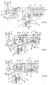
- An electro-hydraulic tensioning device S in Fig. 1 is e.g. Part of a machine tool, like a turning, milling or drilling machine, usually a machine tool, and is used to clamp a workpiece or tool.
- the tensioning device is operated by a higher-level control unit, not shown (electronic control system) performed, for example, by means of electrical signals is continuously informed about operation steps, conditions, the clamping pressure or the like.
- a pressure source P driven by a motor M, provided that sucks from a return T and the hydraulic medium in a Pump line 1 presses.
- a return line 2 leads to the return T a hydraulic motor W, e.g.
- the directional control valve J is a 4/3-way valve with two control positions and a shut-off position and is expedient as a seat valve (at 18) trained so that it is leak-free in shut-off positions.
- the pressure line 19 is connected to a control output of a setting valve D (in the case shown a pressure regulating pressure reducing valve) connected via a line 4 to the Pump line 1 and a line 3 is connected to the return line 2.
- the Adjustment valve D is part of an adjustment device E of the hydraulic control circuit H the tensioning device S.
- the application pressure becomes set to a desired height in each consumer line 16, 17 (clamping pressure), held by the regulating engagement of the adjusting valve D, and if necessary changed. For example, one can be used for finishing or roughing Different clamping pressures are required.
- a proportional pilot valve V and a safety valve B are provided in the adjusting device E.
- a proportional pilot valve V and a safety valve B are provided in the adjusting device E.
- a proportional pilot valve V and a safety valve B are provided in the adjusting device E.
- Fig. 1 is for both consumer lines 16, 17 each have a differential pressure switching valve F with a switch G.
- a control line 5 branches from line 4 to the additional pressure reducing valve A and an input of the proportional pilot valve V.
- the proportional pilot valve V is a pressure control valve with an additional directional function and is operated by means of a proportional magnet 6, which acts against a control spring 7. From the proportional pilot valve V leads a control line 11 to the safety valve B, the Output via a control line 10 with an application chamber Actuating piston 9 and is connected to one side of the differential pressure switching valve F. The other side of the differential pressure switching valve F is connected via a control line 15 the consumer line 16 connected.
- a movable element of the differential pressure switching valve F is generated by a spring 13 in the direction of action in the control line 15 from the consumer line 16 derived from the clamping pressure reference pressure.
- one of the proportional pilot valve V is dependent pilot pressure dependent on the energization of the proportional magnet 6 controlled that the element of the differential pressure switching valve F in the opposite Direction applied.
- the control line 15 is before the differential pressure switching valve F contain a throttle 14.
- the safety valve B in FIG. 1 is a hydraulically unlockable seat valve 51 (2/2 switching valve or ball check valve), the one by a spring 50 and the Element 49 pressurized in the control line 11 in the closing direction (Unlocking piston) contains the pressure in the control line 12 in the opening direction can be acted upon (unlocking pressure for hydraulic unlocking).
- the actuating piston 9 serves as a hydraulically adjustable abutment for a control spring R. a valve element 8 (control piston) of the pressure reducing valve forming the adjusting valve D.
- a pilot pressure> 30 is expedient Bar controlled by the proportional pilot valve V while the system pressure or the consumer pressure is significantly higher and up to 400 bar or more.
- the switch G by means of that on the relationship between the pilot pressure and the clamping pressure or the reference pressure-adjusted differential pressure switching valve F, the correct Reaching the clamping pressure (or missing or falling below) the report higher-level control unit.
- the switch G and the differential pressure switching valve F are coordinated so that the switch G when reached of the predetermined ratio reports the clamping pressure by responding, however with a change in the ratio, for example by lowering the Reference pressure, does not respond.
- a reverse connection is also possible i.e. that the switch does not issue a message when the clamping pressure is present, but instead only if the clamping pressure is missing. As a rule, however, a message is issued "Tension pressure reached" given, due to which the higher-level control unit initiates the next processing step.
- the differential pressure switching valve F works leak-free.
- the hydraulic motor W is expedient also leak-free.
- the directional control valve J blocks the admission line 16, 17 in its shut-off position without leakage.
- the safety valve B in the event of a malfunction (cable break, power failure, pump failure, line break or the like), thanks to the spring 50 automatically goes into the shut-off position, holds the Pilot pressure is leak-free, as is the setting piston 9 of the adjustment valve D. This means maintain the clamping pressure unchanged in the event of a malfunction remains and a correct message of the switch G is possible.
- the second supply line 17 is also through a differential pressure switching valve F and a switch G monitors, but possibly on one other head.
- a dashed line can be found in the pump line 1
- Pressure accumulator 21 can be provided, which is loaded by means of the pump P. When loaded Pressure accumulator 21, pump P can be switched to pressureless circulation, the circulation pressure should be higher than the pilot pressure.
- Fig. 2 differs from that in Fig. 1 in that Directional control valve J consisting of two structurally separate 3/2-way valves in seat valve design (Seat valve 18) is formed, each in only one consumer line 16, 17th is arranged (either for only one hydraulic motor or for two hydraulic motors). Further is a separate one from the working pressure circuit (pump line 1 and return line 2) Control pressure circuit 22 is provided, to which the control line 5 'to the additional pressure reducing valve A or to the proportional pilot valve V.
- Directional control valve J consisting of two structurally separate 3/2-way valves in seat valve design (Seat valve 18) is formed, each in only one consumer line 16, 17th is arranged (either for only one hydraulic motor or for two hydraulic motors). Further is a separate one from the working pressure circuit (pump line 1 and return line 2)
- Control pressure circuit 22 is provided, to which the control line 5 'to the additional pressure reducing valve A or to the proportional pilot valve V.
- Pump P is an electrical switching device (solenoid valve 24 with downstream Pressure limiter 25) provided to the after loading the pressure accumulator 21 Pump P to switch to pressureless circulation, the pump line 1 between the pressure accumulator 21 and the control pressure circuit 22 by a in the backflow direction blocking check valve 23 is secured. After switching to pressureless Circulation (shown in Fig. 2) pumps P through the pressure limiter 25th to the return T, the pressure limiter 25, e.g. set to 25 bar, in the control pressure circuit 22 maintains a pressure sufficient to set the required pilot pressure.
- a function monitoring device K is provided for the safety valve B, which contains an electrical switch that connects to the higher-level control unit is connected to give a message if the safety valve B at a Malfunction (cable break, power failure or the like) has taken the shut-off position orand the pressure fed by the proportional pilot valve is not permitted has dropped.
- the switch is expediently set to a response pressure (or the shut-off position of the safety valve), which is higher than the maximum adjustable pilot pressure and lower than that required to overcome spring 50 Unlocking pressure in the control line 12.
- a first and a second pump P1 and P2 are provided, the pump P1 a has a higher flow rate than pump P2.
- Pump P2 only supplies its own Control circuit 22, via the control line 5 'to the input of the proportional pilot valve V is connected. Because the control circuit 22 through the pressure limiter 25 is secured at a low pressure, for example 25 bar the additional pressure reducing valve A of Fig. 2 is eliminated.
- the first pump P1 supplies the Pump line 1 with a much higher pressure, up to 400 bar and more can be, depending on the desired clamping pressure, or depending on whether still other, not shown in the figure consumers are connected, if necessary are dependent on high system pressure.
- the 3/2-way control valve is trained.
- the differential pressure switching valve serves for the consumer line 16 F with the switch G, which in the control position of the Directional control valve J monitors the pressure in the consumer line 16.
- a pressure source are a pump P1 with medium output and a pump P1 with high Funding provided.
- the pump P1 generates e.g. a high system pressure of 350 bar, while the second pump P2 has a lower system pressure, for example generated only 75 bar.
- the adjusting valve D is a pressure reducing valve in FIG. 4.
- the adjustment valve D 'for the consumer pressure a pressure relief valve (instead of a regulating pressure reducing valve) which measures the pressure in the pump line 1 limited to a height by the control spring R or the pilot pressure the control spring R is set on the adjusting piston 9.
- the directional control valve J is a 4/3-way valve in seat valve design, that is directly connected to pump line 1.
- the pressure source P for example a constant delivery pump P, has an electrical switching device for switching to unpressurized circulation to the return T, namely the solenoid valve 24 with the downstream pressure limiter 25, which is set, for example, to a circulation pressure of 25 bar for non-pressurized circulation for the proportional pilot valve V to generate to ensure the pilot pressure in the control line 10 required pressure level.
- the check valve 23 blocks in the pump line 1.
- the adjusting valve D ' is a pressure relief valve that limits the pressure in the pump line to a pressure level that depends on that Pilot pressure set in the control line on the proportional pilot valve V. 10.
- the control line 5 '' to the additional pressure reducing valve A branches upstream of the adjusting valve D 'on the pump line 1.
- the control line 15 can either be connected to a Consumer line or connected to both consumer lines via a shuttle valve will.
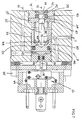
- Fig. 7 is in a housing bore 29 of the differential pressure switching valve F with Sealing means 46 sealed a pot piston 30 with a large contact area A1 slidably guided with a plunger 31 on an actuator 32nd of switch G is aligned.
- the plunger 31 passes through a seal 34 Closure piece 33.
- a piston 35 is sealed in the housing bore 29 slidably guided, the one cylinder section 36 with an action surface A2, which is considerably smaller than the exposure area A1.
- the relationship between the application areas can be between 1: 5 and 1:30, depending on the ratio of the pilot pressure to the reference pressure.
- the piston 35 is one with its cylinder portion 36 in a through bore 38 Washer body 37, which is positioned in the housing bore 29.
- a closure piece 39 Adjacent on the disk body 37, a closure piece 39 is provided, which in a Seal 40 holds a sliding sleeve 41, in which the cylinder section 36 is guided.
- the closure piece 31 delimits a chamber 42 with the disk body 37 connected to the control line 15 for the reference pressure via the throttle 14 (see FIG. 1) is.
- the control line 10 for the pilot pressure leads to the application area A1 of the pot piston 30.
- the disk body 37 forms a spring abutment 47 for the biasing spring 13 (see FIG. 1), which has an annular body 48 as a further Spring abutment acts on the piston 35 in the same sense as the.
- the piston 35 dips into the interior of the pot piston 30 and carries a driving head at the free end 49, which is spherical and preferably has a driving surface 50 conical shape cooperates at the bottom of the pot piston 30.
- a driving head at the free end 49, which is spherical and preferably has a driving surface 50 conical shape cooperates at the bottom of the pot piston 30.
- the Switch G for example a microswitch, is arranged in a switch housing 44, which is expediently adjustable in a frame 45 around the switching point to be able to adjust or adjust.
- the frame 44 is on the differential pressure switching valve F attached.
Abstract
Description
Die Erfindung betrifft eine elektrohydraulische Spannvorrichtung gemäß dem Oberbegriff
des Anspruchs 1.The invention relates to an electro-hydraulic clamping device according to the preamble
of
Bei einer aus DE-A-44 23 541 und DE-A-44 23 585 bekannten Spannvorrichtung für eine Werkzeugmaschine ist der Druckschalter mit dem Regelelement des Einstellventils für den Beaufschlagungsdruck des Hydromotors gekoppelt. Das Einstellventil ist ein Druckminderventil mit einem Regelkolben, dessen Regelfeder über den Stellkolben vom Vorsteuerdruck und vom im Wegesteueventil leckagebehaftet abgezapften Referenzdruck beaufschlagt wird, um den Spanndruck einzustellen. Der Schaltpunkt ist auf eine bestimmte Position des Regelkolbens eingestellt. Da der Regelkolben die Schaltposition für den Schalter unabhängig davon erreicht, in welcher Verbraucherleitung der eingestellte Beaufschlagungsdruck erreicht wird, ist das vom Schalter abgegebene Signal unter bestimmten Betriebszuständen für eine übergeordnete Steuereinheit mehrdeutig. Ferner wird der Regelkolben des Druckminderventils mit dem vollen Druck aus der Druckquelle beaufschlagt, wodurch unvermeidliche Leckagen einen nachteiligen Einfluß auf die Präzision der Druckeinstellung bzw. Drucküberwachung durch den Schalter gewinnen. In der Praxis werden solche Spannvorrichtungen mit moderaten Drücken, z.B. bis 200 Bar, betrieben, auch weil bei höheren Drücken Leckagen stärker würden. Bei modernen Werkzeugmaschinen gibt es jedoch Einsatzfälle, bei denen bei einem höheren Arbeitsdruckniveau, z.B. bis zu 400 Bar trotzdem hohe Betriebs- oder Systemsicherheit gewährleistet sein sollen. Das Sicherheitsventil, das bei Stromausfall oder NOT-AUS-Betätigung selbsttätig den Stellkolben für die Regelfeder des Regelelementes vom Proportional-Vorsteuerventil trennt, sichert zwar die Aufrechterhaltung des eingestellten Spanndrucks. Die Leckage im Einstellventil kann dennoch zum Ansprechen des Schalters führen. Hinzu kommt, daß auch der Referenzdruck aufgrund der Anzapfung im Wegesteuerventil wegen Leckage instabil wird bzw. die Anzapfung bei hohem Systemdruck einen spürbaren Verlust für die am Hydromotor gebrauchte Leistung bedeutet.In a known from DE-A-44 23 541 and DE-A-44 23 585 clamping device for a machine tool is the pressure switch with the control element of the setting valve coupled to the pressure of the hydraulic motor. The adjusting valve is a pressure reducing valve with a control piston, the control spring of which is above the control piston tapped from the pilot pressure and from the leakage in the directional control valve Reference pressure is applied to adjust the clamping pressure. The switching point is set to a certain position of the control piston. Because the control piston reached the switch position for the switch regardless of which consumer line the set pressure is reached, that is from Switch issued signal under certain operating conditions for a higher-level Control unit ambiguous. Furthermore, the control piston of the pressure reducing valve pressurized with the full pressure from the pressure source, making inevitable Leaks have an adverse effect on the precision of the pressure setting or Gain pressure monitoring through the switch. In practice, such Clamps with moderate pressures, e.g. up to 200 bar, also because leakages would increase at higher pressures. With modern machine tools However, there are cases in which a higher working pressure level, e.g. to at 400 bar high operational or system security should still be guaranteed. The safety valve that automatically switches in the event of a power failure or EMERGENCY STOP actuation Control piston for the control spring of the control element from the proportional pilot valve separates, ensures that the set clamping pressure is maintained. The leak in the adjusting valve can still trigger the switch. In addition comes that the reference pressure due to the tap in the directional control valve becomes unstable due to leakage or the tapping is noticeable at high system pressure Loss for the power used on the hydraulic motor means.
Bei einer aus DE-A-44 46 538 bekannten Werkstück-Spannvorrichtung ist der den Spanndruck überwachende Schalter in einem eigenen Ventil enthalten, in welchem ein Differentialkolben den Vorsteuerdruck mit dem Referenzdruck vergleicht. Anstelle des Schalters kann auch ein Analog-Wegaufnehmer oder eine Kraftmeßvorrichtung vorgesehen sein. Der Aufbau dieser Spannvorrichtung ist kompliziert, vor allem hinsichtlich der Regeltechnik und der erforderlichen Elektronik zur Signalauswertung und -verarbeitung. Da der Vorsteuerdruck höher sein muß als der Referenzdruck, ist ein aufwendiges und großbauendes Proportional-Vorsteuerventil erforderlich, das den vollen Druck der Druckquelle verarbeiten muß. Ferner treten auf der Vorsteuerseite unzweckmäßige Leckagen auf.In a workpiece clamping device known from DE-A-44 46 538, the is the Switch pressure monitoring switches contained in a separate valve, in which a differential piston compares the pilot pressure with the reference pressure. Instead of the switch can also be an analog displacement sensor or a force measuring device be provided. The construction of this jig is complicated, especially in terms of the control technology and the necessary electronics for signal evaluation and -processing. Since the pilot pressure must be higher than the reference pressure, is a elaborate and large proportional pilot valve required, which the must process full pressure of the pressure source. Furthermore occur on the input tax side inappropriate leaks.
Weiterer Stand der Technik ist enthalten in DE-A-44 07 370 und DE-A-32 32 536.Further prior art is contained in DE-A-44 07 370 and DE-A-32 32 536.
Der Erfindung liegt die Aufgabe zugrunde, eine elektrohydraulische Spannvorrichtung der eingangs genannten Art zu schaffen, bei der auch bei höheren Drücken, z.B. bis 400 Bar oder mehr, ein hoher Sicherheitsstandard mit präzise ansprechendem Schalter gewährleistet wird.The invention has for its object an electro-hydraulic clamping device to create of the type mentioned, in which even at higher pressures, e.g. to 400 bar or more, a high security standard with precisely responsive Switch is guaranteed.
Die gestellte Aufgabe wird mit den Merkmalen des Anspruchs 1 gelöst.The object is achieved with the features of
Obwohl der Schalter mit dem Differenz-Druckschaltventil baulich getrennt vom Einstellventil angeordnet ist, läßt sich der Schaltpunkt des Schalters ohne direkte Kopplung mit dem Regelelement und elektrisch ferngesteuert über das Proportional-Vorsteuerventil genau an den eingestellten Spanndruck anpassen. Die übergeordnete Steuereinheit erhält unabhängig von der am Proportional-Vorsteuerventil eingestellten Höhe des Spanndrucks die präzise Meldung, ob der Spanndruck erreicht ist, oder nicht. Die Spanndruckmeldung ist eindeutig für die Verbraucherleitung (Bewegungsrichtung des Hydromotors), aus der der Referenzdruck abgeleitet wird. Da der Vorsteuerdruck wesentlich niedriger ist als der Referenzdruck,z.B. unter 30 Bar, und das leckagefrei arbeitende Differenz-Schaltventil den Schaltpunkt des Schalters präzise an den eingestellten Spanndruck anpaßt, eignen sich dafür kleine und leichte Ventilkomponenten und werden auf der Vorsteuerseite Leckagen vermieden. Die Spannvorrichtung ist auch für höhere Systemdrücke von 400 Bar oder mehr geeignet. Das Sicherheitsventil, den Vorsteuerdruck aufrechterhält, ist ebenfalls leckagefrei. Wird auch ein leckagefreier Hydromotor verwendet, dann arbeitet die Peripherie des Schalters verlustfrei. Die Spannvorrichtung ist bevorzugt für Werkstücke und/oder Werkzeuge in Werkzeugmaschinen, insbesondere Automaten, verwendbar, obwohl auch weitere Einsatzbereiche, z.B. in Textilmaschinen, möglich sind.Although the switch with the differential pressure switching valve is structurally separate from the control valve is arranged, the switching point of the switch can be made without direct coupling with the control element and electrically remote-controlled via the proportional pilot valve adapt exactly to the set clamping pressure. The parent Control unit receives regardless of the one set on the proportional pilot valve Height of the clamping pressure the precise message whether the clamping pressure has been reached or Not. The clamping pressure message is clear for the consumer line (direction of movement of the hydraulic motor) from which the reference pressure is derived. Because the pilot pressure is significantly lower than the reference pressure, e.g. under 30 bar, and that Leakage-free differential switching valve the switching point of the switch precisely Adapting to the set clamping pressure, small and light valve components are suitable and leaks are avoided on the input side. The jig is also suitable for higher system pressures of 400 bar or more. The Safety valve that maintains pilot pressure is also leak free. Becomes also uses a leak-free hydraulic motor, then the periphery of the Switch lossless. The clamping device is preferred for workpieces and / or Tools can be used in machine tools, especially automatic machines, though also other areas of application, e.g. in textile machines.
Gemäß Anspruch 2 ist das Differenz-Druckschaltventil in der Absperrstellung des Sicherheitsventils
zu jeder Seite leckagefrei isoliert. Dabei ist es zweckmäßig, wenn in
der Werkzeugmaschine, z.B. einer Drehmaschine, einer Bohrmaschine oder einer
Fräsmaschine, der Hydromotor leckagefrei arbeitet, damit eine ordnungsgemäße
Meldung möglich ist und bei hohen Systemdrücken Leistungsverluste durch Leckagen
vermieden werden.According to
Gemäß Anspruch 3 werden Leckagen bereits beim Abgriff des Referenzdruckes und in der Absperrstellung im Wegesteuerventil vermieden. Das Differenzdruck-Schaltventil und der Schalter sind in ihrer Funktion nicht durch Leckverluste beeinträchtigt. Das Wegesteuerventil als auch bei hohen Drücken leichtgängiges Sitzventil auszulegen, läßt sich mit technisch geringem Aufwand realisieren. Es ergibt sich ein hoher Gesamtwirkungsgrad für die Spannvorrichtung, auch bei hohen Systemdrücken.According to claim 3, leakages are already at the tap of the reference pressure and avoided in the shut-off position in the directional control valve. The differential pressure switching valve and the function of the switch is not affected by leakage. To design the directional control valve as well as smooth seat valve at high pressures, can be realized with little technical effort. The result is a high one Overall efficiency for the clamping device, even at high system pressures.
Das leckagefreie Betriebsverhalten der Spannvorrichtung und der niedrige Vorsteuerdruck, der den Spanndruck bestimmt und sozusagen eine hydraulische Feder für den Schalter definiert, ermöglichen gemäß Anspruch 4, die Druckquelle, z.B. mittels des Signals des Schalters, auf drucklosen Umlauf zu schalten, sobald der eingestellte Verbraucherdruck erreicht ist. Dank des Umlaufdruckes wird der niedrige Vorsteuerdruck dennoch korrekt erzeugt. Dies spart Energie und schont das Hydraulikmedium.The leak-free operating behavior of the tensioning device and the low pilot pressure, which determines the clamping pressure and, so to speak, a hydraulic spring for the Defined switches enable according to claim 4, the pressure source, e.g. by means of the Signals of the switch to switch to pressureless circulation as soon as the set Consumer pressure is reached. Thanks to the circulation pressure, the low pilot pressure nevertheless generated correctly. This saves energy and protects the hydraulic medium.
Gemäß Anspruch 5 wird der Eingangsdruck des Proportional-Vorsteuerventils gegenüber
dem Systemdruck so reduziert, daß der Vorsteuerdruck noch problemlos erzeugbar
und im gewünschten Sinn variierbar bleibt. Die mechanische Belastung auf
der Vorsteuerseite wird auf diese Weise, erheblich reduziert, was der Systemsicherheit
zugute kommt und die Verwendung kleiner, platzsparender und leichter Ventilkomponenten
ermöglicht. According to
Damit das Sicherheitsventil seine vorbestimmte Sicherheitsfunktion jederzeit erbringt,
um den eingestellen Beaufschlagungsdruck bzw. Spanndruck halten zu können und
das ordnungsgemäß Ansprechen des Schalters zu gewährleisten, ist gemäß Anspruch
6 auch die Feder des Sicherheitsventils so auf den Vorsteuerdruck abgestimmt,
daß das Sicherheitsventil sperrt, ehe der Vorsteuerdruck sinken kann.So that the safety valve performs its predetermined safety function at all times,
in order to be able to maintain the set pressure or clamping pressure and
Ensuring that the switch responds properly is in accordance with the
Die Systemsicherheit der Spannvorrichtung wird ferner gemäß Anspruch 7 durch einen Funktionsmelder am Sicherheitsventil erhöht, der beispielsweise bei einem Kabelbruch, einem Stromausfall, einem Pumpenausfall oder einem Leitungsbruch die übergeordnete Steuereinheit informiert, die aufgrund der Spanndruckmeldung die Störung zunächst nicht feststellen können. Die Störung ließe sich gegebenenfalls erst feststellen, wenn sich der Spanndruck nicht mehr verstellen läßt. Dann könnten jedoch Schäden aufgetreten oder nicht mehr zu verhindern sein.The system security of the tensioning device is further according to claim 7 by a Function detector on the safety valve increased, for example in the event of a cable break, a power failure, a pump failure or a line break superordinate control unit informs the due to the clamping pressure message Cannot determine the fault initially. If necessary, the disruption could be solved first determine if the clamping pressure can no longer be adjusted. Then however Damage has occurred or can no longer be prevented.
Gemäß Anspruch 8 wird für den Vorsteuerdruck ein eigener Steuerdruckkreis, gegebenenfalls mit einer eigenen Pumpe, verwendet. Dies hat den Vorteil, daß das Hydraulikmedium für die Vorsteuerung nicht zuvor unnötig auf den hohen Systemdruck gebracht zu werden braucht, und der Vorsteuerbereich unabhängig von der Höhe des Systemdrucks ist. Ferner läßt sich ein Zusatz-Druckminderventil stromauf des Proportional-Vorsteuerventils einsparen.According to claim 8, a separate control pressure circuit for the pilot pressure, if necessary with its own pump. This has the advantage that the hydraulic medium not necessary for the pilot control to the high system pressure needs to be brought, and the input tax range regardless of the amount of the System pressure. Furthermore, an additional pressure reducing valve can be located upstream of the proportional pilot valve save on.
Gemäß Anspruch 9 wird, insbesondere für einen Speicherladebetrieb mittels eines
Druckspeichers, bei auf drucklosen Umlauf geschalteter Druckquelle die ordnungsgemäße
Versorgung des Proportional-Vorsteuerventils mit dem zum Einstellen des
Vorsteuerdrucks notwendigen Druck gewährleistet. Da die volle Förderleistung der
Druckquelle nur zum Laden des Speichers benötigt wird, arbeitet die Spannvorrichtung
effektiv und für das Hydraulikmedium schonend.According to
Gemäß Anspruch 10 meldet der Schalter den Spanndruck nur in einer Verbraucherleitung
des Hydromotors, so daß die übergeordnete Steuereinheit präzise darüber informiert
wird, ob in dieser Arbeitsrichtung des Hydromotors der Spanndruck erreicht
worden ist oder nicht. According to
Gemäß Anspruch 11 werden beide Arbeitsrichtungen des Hydromotors jeweils getrennt
überwacht und der übergeordneten Steuereinheit aussagefähige Signale
übermittelt. Es ist möglich, in beiden Verbraucherleitungen, z.B. bei einem doppelseitig
beaufschlagbaren Hydromotor, unterschiedliche Drücke zu überwachen.According to
Gemäß Anspruch 12 wird eine Verbraucherleitung überwacht oder die jeweils den höheren
Verbraucherdruck führende Verbraucherleitung. Um der übergeordneten Steuereinheit
dennoch aussagefähige Signale zur überwachten Arbeitsrichtung des Hydromotors
zu geben, kann hierfür eine zusätzliche Überwachungsvorrichtung vorgesehen
sein.According to
Gemäß Anspruch 13 wirkt im Differenz-Druckschaltventil die Feder gegen den Vorsteuerdruck,
damit das Differenz-Druckschaltventil über den gesamten Druckbereich
des Proportional-Vorsteuerventils dem Schalter ein die Relation zwischen Referenzdruck
und Vorsteuerdruck präzise repräsentierendes Vergleichsresultat anbietet. Der
Schaltpunkt des Schalters liegt über den gesamten Druckbereich des Einstellventils
bzw. Strombereich des Proportional-Vorsteuerventils möglichst knapp unterhalb des
Spanndrucks. Aufgrund der Schalterhysterese gibt es zwar einen oberen und einen
unteren Schaltpunkt knapp unterhalb des Spanndrucks. Ohne die Feder würde sonst
bei niedrigem Spanndruck der Schaltpunkt oberhalb des Spanndruckes liegen oder
bei hohem Spanndruck zu weit unterhalb des Spanndrucks. Die Feder schmiegt sozusagen
alle Schaltpunkte eng an die Druckkurve des Spanndruckes an.According to
Anhand der Zeichnung werden Ausführungsformen des Erfindungsgegenstandes erläutert. Es zeigen:
- Fig. 1
- in Form eines Blockschaltbildes eine erste Ausführungsform einer elektrohydraulischen Spannvorrichtung, insbesondere einer Werkstück- oder Werkzeug-Spannvorrichtung,
- Fig. 2
- ein Blockschaltbild einer weiteren Ausführungsform,
- Fig. 3
- ein Blockschaltbild einer weiteren Ausführungsform,
- Fig. 4
- ein Blockschaltbild einer weiteren Ausführungsform,
- Fig. 5
- ein Blockschaltbild einer weiteren Ausführungsform,
- Fig. 6
- ein Blockschaltbild einer weiteren Ausführungsform, und
- Fig. 7
- eine Ausführungsform einer Komponente, wie sie in den elektrohydraulischen
Spannvorrichtungen gemäß den Fig. 1
bis 6 zum Überwachen des Spanndrucks verwendbar ist.
- Fig. 1
- in the form of a block diagram, a first embodiment of an electrohydraulic clamping device, in particular a workpiece or tool clamping device,
- Fig. 2
- 2 shows a block diagram of a further embodiment,
- Fig. 3
- 2 shows a block diagram of a further embodiment,
- Fig. 4
- 2 shows a block diagram of a further embodiment,
- Fig. 5
- 2 shows a block diagram of a further embodiment,
- Fig. 6
- a block diagram of a further embodiment, and
- Fig. 7
- an embodiment of a component, as can be used in the electrohydraulic clamping devices according to FIGS. 1 to 6 for monitoring the clamping pressure.
Eine elektrohydraulische Spannvorrichtung S in Fig. 1 ist z.B. Teil einer Werkzeugmaschine,
wie einer Dreh-, einer Fräs- oder eine Bohrmaschine, meist eines Werkzeugmaschinenautomaten,
und dient zum Spannen eines Werkstücks oder Werkzeugs.
Die Spannvorrichtung wird durch eine übergeordnete, nicht gezeigte Steuereinheit
(elektronisches Steuersystem) geführt, die beispielsweise mittels elektrischer Signale
über Operationsschritte, Zustände, den Spanndruck oder dgl. laufend informiert wird.
Zur hydraulischen Versorgung ist eine Druckquelle P, getrieben durch einen Motor M,
vorgesehen, die aus einem Rücklauf T ansaugt und das Hydraulikmedium in eine
Pumpenleitung 1 drückt. Zum Rücklauf T führt eine Rücklaufleitung 2. Gesteuert wird
ein Hydromotor W, z.B. ein einfach wirkender oder doppelt wirkender Hydraulikzylinder
oder Hydraulikmotor, der über Verbraucherleitungen 16, 17 und ein Wegesteuerventil
J mit einer Druckleitung 19 einerseits und einer Rücklaufleitung 20 andererseits
verbunden bzw. verbindbar ist. Das Wegesteuerventil J ist ein 4/3-Wegeventil mit
zwei Steuerstellungen und einer Absperrstellung und ist zweckmäßigerweise als Sitzventil
(bei 18) ausgebildet, so daß es in Absperrstellungen leckagefrei ist. Die Druckleitung
19 ist an einen Regelausgang eines Einstellventils D (im gezeigten Fall eines
druckregelnden Druckminderventils) angeschlossen, das über eine Leitung 4 mit der
Pumpenleitung 1 und eine Leitung 3 mit der Rücklaufleitung 2 verbunden ist. Das
Einstellventil D ist Teil einer Einstell-Vorrichtung E des hydraulischen Steuerkreises H
der Spannvorrichtung S. Mit der Einstellvorrichtung E wird der Beaufschlagungsdruck
in jeder Verbraucherleitung 16, 17 auf eine gewünschte Höhe eingestellt (Spanndruck),
durch den regelnden Eingriff des Einstellventils D gehalten, und bei Bedarf
verändert. Beispielsweise können für eine Schlicht- oder eine Schruppbearbeitung eines
Werkstücks unterschiedliche Spanndrücke benötigt werden.An electro-hydraulic tensioning device S in Fig. 1 is e.g. Part of a machine tool,
like a turning, milling or drilling machine, usually a machine tool,
and is used to clamp a workpiece or tool.
The tensioning device is operated by a higher-level control unit, not shown
(electronic control system) performed, for example, by means of electrical signals
is continuously informed about operation steps, conditions, the clamping pressure or the like.
For the hydraulic supply there is a pressure source P, driven by a motor M,
provided that sucks from a return T and the hydraulic medium in a
In der Einstellvorrichtung E sind ferner ein Zusatz-Druckminderventil A, ein Proportional-Vorsteuerventil V und ein Sicherheitsventil B vorgesehen. Zur genauen Funktionsweise und zum Aufbau des Proportional-Vorsteuerventils V und des Sicherheitsventils W wird hingewiesen auf DE-A-44 23 585 und DE-A-44 23 541.In the adjusting device E there are also an additional pressure reducing valve A, a proportional pilot valve V and a safety valve B are provided. For the exact functioning and for the construction of the proportional pilot valve V and the safety valve W is referred to DE-A-44 23 585 and DE-A-44 23 541.
Das Erreichen, Verfehlen oder Unterschreiten des Spanndrucks im Hydromotor W
wird mittels wenigstens eines elektrischen Schalters G an die übergeordnete Steuereinheit
gemeldet. Der Schalter G ist in einem Differenzdruck-Schaltventil F angeordnet
oder baulich mit diesem verbunden. In Fig. 1 ist für beide Verbraucherleitungen
16, 17 jeweils ein Differenz-Druckschaltventil F mit einem Schalter G vorgesehen.Reaching, missing or falling below the clamping pressure in the hydraulic motor W
is sent to the higher-level control unit by means of at least one electrical switch G.
reported. The switch G is arranged in a differential pressure switching valve F.
or structurally connected to it. In Fig. 1 is for both
Von der Leitung 4 zweigt eine Steuerleitung 5 zum Zusatz-Druckminderventil A und
einem Eingang des Proportional-Vorsteuerventils V ab. Das Proportional-Vorsteuerventil
V ist ein Druckregelventil mit einer zusätzlichen Wegefunktion und wird betätigt
mittels eines Proportionalmagneten 6, der gegen eine Regelfeder 7 wirkt. Vom Proportional-Vorsteuerventil
V führt eine Steuerleitung 11 zum Sicherheitsventil B, dessen
Ausgang über eine Steuerleitung 10 mit einer Beaufschlagungskammer eines
Stellkolbens 9 und mit einer Seite des Differenzdruck-Schaltventils F verbunden ist.
Die andere Seite des Differenzdruck-Schaltventils F ist über eine Steuerleitung 15 mit
der Verbraucherleitung 16 verbunden. Ein bewegliches Element des Differenzdruck-Schaltventils
F wird durch eine Feder 13 in Wirkrichtung eines in der Steuerleitung 15
aus der Verbraucherleitung 16 vom Spanndruck abgeleiteten Referenzdrucks beaufschlagt.
In der Steuerleitung 10 wird ein vom Proportional-Vorsteuerventil V in Abhängigkeit
von der Bestromung des Proportionalmagneten 6 abhängiger Vorsteuerdruck
eingesteuert, der das Element des Differenzdruck-Schaltventils F in der entgegengesetzten
Richtung beaufschlagt. In der Steuerleitung 15 ist vor dem Differenzdruck-Schaltventil
F ein Drossel 14 enthalten.A
Das Sicherheitsventil B ist in Fig. 1 ein hydraulisch entsperrbares Sitzventil 51 (2/2-Schaltventil
oder Kugel-Rückschlagventil), das ein durch eine Feder 50 und den
Druck in der Steuerleitung 11 in Schließrichtung beaufschlagtes Element 49
(Entsperrkolben) enthält, das in Öffnungsrichtung vom Druck in der Steuerleitung 12
beaufschlagbar ist (Entsperrdruck zum hydraulischen Entsperren).The safety valve B in FIG. 1 is a hydraulically unlockable seat valve 51 (2/2 switching valve
or ball check valve), the one by a
Der Stellkolben 9 dient als hydraulisch verstellbares Widerlager für eine Regelfeder R
eines Ventilelementes 8 (Regelkolben) des das Einstellventil D bildenden Druckminderventils.
Der in seiner Höhe von der Bestromung des Proportionalmagneten 6 abhängige
Vorsteuerdruck, den das Proportional-Vorsteuerventil V unabhängig von
Druckänderungen in der Steuerleitung 10 einregelt, bestimmt über den Stellkolben 9
die wirksame Federkraft der Regelfeder R und somit die Druckhöhe des Spanndrucks
in der Beaufschlagungsleitung 16 bzw. 17. Zweckmäßig wird ein Vorsteuerdruck > 30
Bar vom Proportional-Vorsteuerventil V eingesteuert, während der Systemdruck oder
der Verbraucherdruck wesentlich höher und bis zu 400 Bar oder mehr beträgt. Da das
Verhältnis zwischen dem Vorsteuerdruck und dem Spanndruck bzw. Beaufschlagungsdruck
über den gesamten Arbeitsbereich gleich bleibt, kann der Schalter G
mittels des das auf das Verhältnis zwischen dem Vorsteuerdruck und dem Spanndruck
bzw. dem Referenzdruck abgestimmte Differenzdruck-Schaltventils F, das korrekte
Erreichen des Spanndrucks (oder das Verfehlen bzw. das Unterschreiten) der
übergeordneten Steuereinheit melden. Der Schalter G und das Differenzdruck-Schaltventil
F sind derart aufeinander abgestimmt, daß der Schalter G bei Erreichen
des vorbestimmten Verhältnisses den Spanndruck durch Ansprechen meldet, hingegen
bei einer Veränderung des Verhältnisses, beispielsweise durch Absinken des
Referenzdrucks, nicht anspricht. Eine umgekehrte Verschaltung ist ebenfalls möglich,
d.h., daß der Schalter bei Vorliegen des Spanndrucks keine Meldung abgibt, sondern
erst bei Verfehlen des Spanndrucks. Im Regelfall wird jedoch eine Meldung
"Spanndruck erreicht" abgegeben, aufgrund dere die übergeordnete Steuereinheit
den nächsten Bearbeitungsschritt einleitet.The
Das Differenz-Druckschaltventil F arbeitet leckagefrei. Der Hydromotor W ist zweckmäßigerweise
ebenfalls leckagefrei. Das Wegesteuerventil J sperrt die Beaufschlagungsleitung
16, 17 in seinerAbsperrstellung leckagefrei ab. Das Sicherheitsventil B,
das bei einer Funktionsstörung (Kabelbruch, Stromausfall, Pumpenausfall, Leitungsbruch
oder dgl.), dank der Feder 50 selbsttätig in die Absperrstellung geht, hält den
Vorsteuerdruck leckagefrei, wie auch der Stellkolben 9 des Einstellventils D. Dies bedeutet,
daß bei einer Funktionsstörung der Spanndruck unverändert aufrechterhalten
bleibt und auch eine korrekte Meldung des Schalters G möglich ist.The differential pressure switching valve F works leak-free. The hydraulic motor W is expedient
also leak-free. The directional control valve J blocks the
Falls erforderlich, wird auch die zweite Beaufschlagungsleitung 17 durch ein Differenz-Druckschaltventil
F und einen Schalter G überwacht, gegebenenfalls jedoch auf einer
anderen Druckhöhe. In der Pumpenleitung 1 kann ein gestrichelt angedeuteter
Druckspeicher 21 vorgesehen sein, der mittels der Pumpe P geladen wird. Bei geladenem
Druckspeicher 21 kann die Pumpe P auf drucklosen Umlauf geschaltet werden,
wobei der Umlaufdruck höher als der Vorsteuerdruck sein sollte.If necessary, the
Die Ausführungsform in Fig. 2 unterscheidet sich von der in Fig. 1 dadurch, daß das
Wegesteuerventil J aus zwei baulich getrennten 3/2-Wegeventilen in Sitzventilbauweise
(Sitzventil 18) gebildet ist, deren jedes in nur einer Verbraucherleitung 16, 17
angeordnet ist (entweder für nur einen Hydromotor oder für zwei Hydromotoren). Ferner
ist ein vom Arbeitsdruckkreis (Pumpenleitung 1 und Rücklaufleitung 2) getrennter
Steuerdruckkreis 22 vorgesehen, an den die Steuerleitung 5' zum Zusatz-Druckminderventil
A bzw. zum Proportional-Vorsteuerventil V anschließt. Bei der
Pumpe P ist eine elektrische Umschaltvorrichtung (Magnetventil 24 mit nachgeordnetem
Druckbegrenzer 25) vorgesehen, um nach Laden des Druckspeichers 21 die
Pumpe P auf drucklosen Umlauf zu schalten, wobei die Pumpenleitung 1 zwischen
dem Druckspeicher 21 und dem Steuerdruckkreis 22 durch ein in Rückströmrichtung
sperrendes Rückschlagventil 23 abgesichert ist. Nach der Umschaltung auf drucklosen
Umlauf (in Fig. 2 dargestellt) fördert die Pumpe P über den Druckbegrenzer 25
zum Rücklauf T, wobei der Druckbegrenzer 25, z.B. eingestellt auf 25 Bar, im Steuerdruckkreis
22 einen Druck hält, der ausreicht, den erforderlichen Vorsteuerdruck einzustellen.
Beim Sicherheitsventil B ist eine Funktionsüberwachungsvorrichtung K vorgesehen,
die einen elektrischen Schalter enthält, der mit der übergeordneten Steuereinheit
verbunden ist, um eine Meldung zu geben, falls das Sicherheitsventil B bei einer
Funktionsstörung (Kabelbruch, Stromausfall oder dgl.) die Absperrstellung eingenommen
bzw.und der vom Proportional-Vorsteuerventil eingespeiste Druck unzulässig
abgefallen ist. Zweckmäßigerweise ist der Schalter auf einen Ansprechdruck (oder
die Absperrposition des Sicherheitsventils) eingestellt, der höher ist als der maximal
einstellbare Vorsteuerdruck und niedriger als der zum Überwinden der Feder 50 erforderliche
Entsperrdruck in der Steuerleitung 12.The embodiment in Fig. 2 differs from that in Fig. 1 in that
Directional control valve J consisting of two structurally separate 3/2-way valves in seat valve design
(Seat valve 18) is formed, each in only one
In der Ausführungsform in Fig. 3 sind im Unterschied zur Ausführungsform in Fig. 2
eine erste und eine zweite Pumpe P1 und P2 vorgesehen, wobei die Pumpe P1 eine
größere Förderleistung hat als die Pumpe P2. Die Pumpe P2 versorgt nur den eigenen
Steuerkreis 22, der über die Steuerleitung 5' an den Eingang des Proportional-Vorsteuerventils
V angeschlossen ist. Da der Steuerkreis 22 durch den Druckbegrenzer
25 auf einem niedrigen Druck, beispielsweise 25 Bar, abgesichert ist, kann
das Zusatz-Druckminderventil A von Fig. 2 entfallen. Die erste Pumpe P1 versorgt die
Pumpenleitung 1 mit einem wesentlich höheren Druck, der bis zu 400 Bar und mehr
betragen kann, abhängig vom gewünschten Spanndruck, oder abhängig davon, ob
noch weitere, in der Figur nicht dargestellte Verbraucher angeschlossen sind, die gegebenfalls
auf einen hohen Systemdruck angewiesen sind.In the embodiment in FIG. 3, in contrast to the embodiment in FIG. 2,
a first and a second pump P1 and P2 are provided, the pump P1 a
has a higher flow rate than pump P2. Pump P2 only supplies its
In der Ausführungsform in Fig. 4 ist im Unterschied zur Ausführungsform in Fig. 2 nur
ein Wegesteuerventil J in der Verbraucherleitung 16 vorgesehen, das als 3/2-Wegesteuerventil
ausgebildet ist. Für die Verbraucherleitung 16 dient das Differenz-Druckschaltventil
F mit dem Schalter G, das in der nicht gezeigten Steuerstellung des
Wegesteuerventils J den Druck in der Verbraucherleitung 16 überwacht. Als Druckquelle
sind eine Pumpe P1 mit mittlerer Förderteistung und eine Pumpe P1 mit hoher
Förderleistung vorgesehen. Die Pumpe P1 erzeugt z.B. einen hohen Systemdruck
von 350 Bar, während die zweite Pumpe P2 einen niedrigeren Systemdruck von beispielsweise
nur 75 Bar erzeugt. In dem angedeuteten Zwischenraum zwischen der
Druckquelle und der Einstellvorrichtung E können weitere, nicht gezeigte Verbraucher
vorgesehen sein. Das Einstellventil D ist in Fig. 4 ein Druckminderventil.In the embodiment in FIG. 4, in contrast to the embodiment in FIG. 2, only
a directional control valve J is provided in the
In derAusführungsform vonFig. 5 ist im Unterschied zu den vorhergehenden Ausführungsformen
das Einstellventil D' für den Verbraucherdruck ein Druckbegrenzungsventil
(anstelle eines regelnden Druckminderventils), das den Druck in der Pumpenleitung
1 auf eine Höhe begrenzt, die durch die Regelfeder R bzw. den Vorsteuerdruck
auf dem Stellkolben 9 der Regelfeder R eingestellt ist. Die Steuerleitung 5'' zum Zusatz-Druckminderventil
A stromauf des Porportional-Vorsteuerventils V und eine Vorsteuerleitung
27 des Druckbegrenzungsventils D' zweigen an einem Punkt 26 von der
Pumpenleitung 1 ab. Das Wegesteuerventil J ist ein 4/3-Wegeventil in Sitzventilbauweise,
das direkt an die Pumpenleitung 1 angeschlossen ist. Von den Verbraucherleitungen
16, 17 zweigen die Steuerleitungen 15', 15'' ab, die, gegebenenfalls, zu einem
Wechselventil 28 führen, von dem die Steuerleitung 15 zum Differenzdruck-Schaltventil
F des Schalters G führt. Sofern nur eine Verbraucherleitung 16 oder 17 überwacht
werden soll, wird die jeweilige Steuerleitung 15' oder 15'' direkt mit der Steuerleitung
15 verbunden. Die Druckquelle P, beispielsweise eine Konstantförderpumpe
P, weist eine elektrische Umschaltvorrichtung zum Umschalten auf drucklosen Umlauf
zum Rücklauf T auf, und zwar das Magnetventil 24 mit dem nachgeordneten Druckbegrenzer
25, der beispielsweise auf einen Umlaufdruck von 25 Bar eingestellt ist, um
bei drucklosem Umlauf dennoch für das Proportional-Vorsteuerventil V die zum Erzeugen
des Vorsteuerdrucks in der Steuerleitung 10 erforderliche Druckhöhe zu gewährleisten.
Bei drucklosem Umlauf sperrt das Rückschlagventil 23 in der Pumpenleitung
1.In the embodiment of FIG. 5 is different from the previous embodiments
the adjustment valve D 'for the consumer pressure a pressure relief valve
(instead of a regulating pressure reducing valve) which measures the pressure in the
In Fig. 6 ist ähnlich wie in Fig. 5 das Einstellventil D' ein Druckbegrenzungsventil, das
den Druck in der Pumpenleitung auf eine Druckhöhe begrenzt, die abhängt von dem
am Proportional-Vorsteuerventil V eingestellten Vorsteuerdruck in der Steuerleitung
10. Die Steuerleitung 5'' zum Zusatz-Druckminderventil A zweigt stromauf des Einstellventils
D' an der Pumpenleitung 1 ab. Die Steuerleitung 15 kann entweder an eine
Verbraucherleitung oder über ein Wechselventil an beide Verbraucherleitungen angeschlossen
werden.In Fig. 6, similar to Fig. 5, the adjusting valve D 'is a pressure relief valve that
limits the pressure in the pump line to a pressure level that depends on that
Pilot pressure set in the control line on the proportional pilot valve V.
10. The control line 5 '' to the additional pressure reducing valve A branches upstream of the adjusting valve
D 'on the
In Fig. 7 ist in einer Gehäusebohrung 29 des Differenzdruck-Schaltventils F mit
Dichtmitteln 46 ein Topfkolben 30 mit einer großen Beaufschlagungsfläche A1 abgedichtet
verschieblich geführt, der mit einem Stößel 31 auf ein Betätigungselement 32
des Schalters G ausgerichtet ist. Der Stößel 31 durchsetzt eine Dichtung 34 eines
Verschlußstücks 33. Ferner wird in der Gehäusebohrung 29 ein Kolben 35 abgedichtet
verschieblich geführt, der einen Zylinderabschnitt 36 mit einer Beaufschlagungsfläche
A2 aufweist, die erheblich kleiner ist als die Beaufschlagungsfläche A1. Das Verhältnis
zwischen den Beaufschlagungsflächen kann zwischen 1:5 und 1:30 betragen,
abhängig davon, in welchem Verhältnis der Vorsteuerdruck zum Referenzdruck steht.
Der Kolben 35 ist mit seinem Zylinderabschnitt 36 in einer Durchgangsbohrung 38 eines
Scheibenkörpers 37 gefüht, der in der Gehäusebohrung 29 positioniert ist. Angrenzend
an den Scheibenkörper 37 ist ein Verschlußstück 39 vorgesehen, das in einer
Dichtung 40 eine Gleithülse 41 hält, in der der Zylinderabschnitt 36 geführt wird.
Das Verschlußstück 31 begrenzt mit dem Scheibenkörper 37 eine Kammer 42, die
über die Drossel 14 (s. Fig. 1) an die Steuerleitung 15 für den Referenzdruck angeschlossen
ist. Die Steuerleitung 10 für den Vorsteuerdruck führt zur Beaufschlagungsfläche
A1 des Topfkolbens 30. Der Scheibenkörper 37 bildet ein Federwiderlager
47 für die Vorspannfeder 13 (s. Fig. 1), die über einen Ringkörper 48 als weiteres
Federwiderlager den Kolben 35 im gleichen Sinn beaufschlagt wie der. Der Kolben 35
taucht in den Innenraum des Topfkolbens 30 ein und trägt am freien Ende einen Mitnehmerkopf
49, der ballig ausgebildet ist und mit einer Mitnehmerfläche 50 von vorzugsweise
kegeliger Form am Boden des Topfkolbens 30 zusammenarbeitet. Der
Schalter G, beispielsweise ein Mikroschalter, ist in einem Schaltergehäuse 44 an geordnet,
das zweckmäßigerweise in einem Rahmen 45 verstellbar ist, um den Schaltpunkt
einjustieren oder verstellen zu können. Der Rahmen 44 ist am Differenzdruck-Schaltventil
F befestigt.In Fig. 7 is in a housing bore 29 of the differential pressure switching valve F with
Sealing means 46 sealed a
In Fig. 7 ist der Spanndruck ordnungsgemäß erreicht. Der Kolben 35 drückt zusammen
mit der Feder 13 den Stößel 31 gegen das Betätigungselement 32. Der Schalter
G meldet "Spanndruck erreicht". Sinkt der Referenzdruck aus dem Spanndruck, dann
verstellt sich der Topfkolben 30 unter dem Vorsteuerdruck nach links, bis der Stößel
31 das Betätigungselement 32 freigibt. Der Schalter G meldet "Spanndruck nicht vorhanden
oder verfehlt oder unterschritten".In Fig. 7 the clamping pressure has been properly reached. The
Wird durch Verstellen des Proportionalmagneten 6 der Vorsteuerdruck angehoben,
dann verschiebt sich der Topfkolben 30 aus der Lage gemaß Fig. 7 nach links. Der
Schalter G meldet "Spanndruck nicht vorhanden". Sobald über das Einstellventil D
bzw. D' der Verbraucherdruck entsprechend dem neuen Wert des Vorsteuerdrucks
angehoben ist, verstellt sich der Topfkolben 30 erneut nach rechts, bis der Schalter G
meldet "Spanndruck erreicht".If the pilot pressure is raised by adjusting the
Claims (13)
Applications Claiming Priority (2)
| Application Number | Priority Date | Filing Date | Title |
|---|---|---|---|
| DE29710129U | 1997-06-10 | ||
| DE29710129U DE29710129U1 (en) | 1997-06-10 | 1997-06-10 | Electro-hydraulic clamping device |
Publications (2)
| Publication Number | Publication Date |
|---|---|
| EP0884484A1 true EP0884484A1 (en) | 1998-12-16 |
| EP0884484B1 EP0884484B1 (en) | 2003-03-19 |
Family
ID=8041448
Family Applications (1)
| Application Number | Title | Priority Date | Filing Date |
|---|---|---|---|
| EP98107637A Expired - Lifetime EP0884484B1 (en) | 1997-06-10 | 1998-04-27 | Electrohydraulic clamping device |
Country Status (3)
| Country | Link |
|---|---|
| EP (1) | EP0884484B1 (en) |
| AT (1) | ATE235006T1 (en) |
| DE (2) | DE29710129U1 (en) |
Cited By (1)
| Publication number | Priority date | Publication date | Assignee | Title |
|---|---|---|---|---|
| EP1371853A1 (en) | 2002-06-10 | 2003-12-17 | HAWE Hydraulik GmbH & Co. KG | Electrohydraulic clamping device |
Families Citing this family (4)
| Publication number | Priority date | Publication date | Assignee | Title |
|---|---|---|---|---|
| DE29808294U1 (en) | 1998-05-07 | 1998-08-13 | Heilmeier & Weinlein | Electro-hydraulic clamping module |
| DE102011107722B3 (en) | 2011-07-18 | 2012-10-31 | Hohenstein Vorrichtungsbau Und Spannsysteme Gmbh | Device for use with safety components for fixing and clamping of workpieces during form-changing manufacturing process on machine tool, has clamping center wall or two outer walls arranged perpendicularly on horizontal device base plate |
| EP2597317B1 (en) * | 2011-11-22 | 2014-01-15 | HAWE Hydraulik SE | motor pump unit for a machine tool |
| CN113007159B (en) * | 2021-02-09 | 2023-03-10 | 中国煤炭科工集团太原研究院有限公司 | Hydraulic tensioning method, hydraulic tensioning device and continuous miner |
Citations (5)
| Publication number | Priority date | Publication date | Assignee | Title |
|---|---|---|---|---|
| DE3232536A1 (en) | 1982-09-01 | 1984-03-01 | Herion-Werke Kg, 7012 Fellbach | VALVE ARRANGEMENT FOR CONTROLLING AND MONITORING THE WORKING PRESSURE OF A CONSUMER |
| DE4423541A1 (en) | 1993-07-21 | 1995-01-26 | Heilmeier & Weinlein | Proportional pressure regulating valve of slider construction |
| DE4423585A1 (en) | 1993-07-21 | 1995-01-26 | Heilmeier & Weinlein | Electrohydraulic control device |
| DE4407370A1 (en) | 1994-03-05 | 1995-09-07 | Bosch Gmbh Robert | Control and monitoring of pressure for hydraulic motor used to hold workpiece in machine tool |
| DE4446538A1 (en) * | 1994-12-24 | 1996-06-27 | Bosch Gmbh Robert | Hydraulic tensioning device e.g. for programmable machine tool |
-
1997
- 1997-06-10 DE DE29710129U patent/DE29710129U1/en not_active Expired - Lifetime
-
1998
- 1998-04-27 AT AT98107637T patent/ATE235006T1/en not_active IP Right Cessation
- 1998-04-27 EP EP98107637A patent/EP0884484B1/en not_active Expired - Lifetime
- 1998-04-27 DE DE59807517T patent/DE59807517D1/en not_active Expired - Lifetime
Patent Citations (5)
| Publication number | Priority date | Publication date | Assignee | Title |
|---|---|---|---|---|
| DE3232536A1 (en) | 1982-09-01 | 1984-03-01 | Herion-Werke Kg, 7012 Fellbach | VALVE ARRANGEMENT FOR CONTROLLING AND MONITORING THE WORKING PRESSURE OF A CONSUMER |
| DE4423541A1 (en) | 1993-07-21 | 1995-01-26 | Heilmeier & Weinlein | Proportional pressure regulating valve of slider construction |
| DE4423585A1 (en) | 1993-07-21 | 1995-01-26 | Heilmeier & Weinlein | Electrohydraulic control device |
| DE4407370A1 (en) | 1994-03-05 | 1995-09-07 | Bosch Gmbh Robert | Control and monitoring of pressure for hydraulic motor used to hold workpiece in machine tool |
| DE4446538A1 (en) * | 1994-12-24 | 1996-06-27 | Bosch Gmbh Robert | Hydraulic tensioning device e.g. for programmable machine tool |
Cited By (1)
| Publication number | Priority date | Publication date | Assignee | Title |
|---|---|---|---|---|
| EP1371853A1 (en) | 2002-06-10 | 2003-12-17 | HAWE Hydraulik GmbH & Co. KG | Electrohydraulic clamping device |
Also Published As
| Publication number | Publication date |
|---|---|
| EP0884484B1 (en) | 2003-03-19 |
| DE59807517D1 (en) | 2003-04-24 |
| ATE235006T1 (en) | 2003-04-15 |
| DE29710129U1 (en) | 1997-08-14 |
Similar Documents
| Publication | Publication Date | Title |
|---|---|---|
| DE10319484B4 (en) | Hydraulic control system | |
| DE10013194B4 (en) | driving device | |
| EP1598560B1 (en) | Hydraulic valve assembly | |
| EP0473030A1 (en) | Proportional 4-way seat valve | |
| DE1916224A1 (en) | Hydraulic pump control circuit | |
| DE3347000A1 (en) | Electrohydraulic arrangement for controlling a double-acting hydraulic motor | |
| DE3021927A1 (en) | ELECTRONIC CONTROL DEVICE FOR ADJUSTABLE PUMPS | |
| DE4302755A1 (en) | Parameter control system for hydraulic equipment, e.g. for torque control of drill spindle e.g. of rock drilling machine | |
| EP0955471B1 (en) | Electrohydraulic clamping module | |
| DE102016124118B4 (en) | Hydraulic drive with rapid and load lift | |
| DE3836453A1 (en) | Valve arrangement for controlling and monitoring the working pressure of a hydraulic consumer | |
| EP0884484B1 (en) | Electrohydraulic clamping device | |
| DE4446538A1 (en) | Hydraulic tensioning device e.g. for programmable machine tool | |
| EP0884486B1 (en) | Electrohydraulic clamping device | |
| DE4237901C2 (en) | Electro-hydraulic control device and pressure reducing valve | |
| EP0955472A1 (en) | Seat valve | |
| DE4423585A1 (en) | Electrohydraulic control device | |
| EP0241870A2 (en) | Hydraulic control device | |
| DE3039002C2 (en) | Pressure control valve | |
| EP0884483B1 (en) | Differential pressure switch | |
| EP0884476A2 (en) | Pressure limiting control circuit for the safe operation of a variable displacement radial or axial hydraulic piston pump or vane cell machine | |
| DE4140423A1 (en) | System for regulating pressure of hydraulic working fluid in machine - has hydraulically operated control valve and pressure transducers for signalling pressure to comparator in electronic controller | |
| DE3110210A1 (en) | Hydraulic operating device for controlling the working and stoppage phases of machines or machine tools | |
| EP0707147B1 (en) | Control device for a hydrostatic machine | |
| EP0798470B1 (en) | Electro-hydraulic control system |
Legal Events
| Date | Code | Title | Description |
|---|---|---|---|
| PUAI | Public reference made under article 153(3) epc to a published international application that has entered the european phase |
Free format text: ORIGINAL CODE: 0009012 |
|
| AK | Designated contracting states |
Kind code of ref document: A1 Designated state(s): AT BE CH DE DK ES FR GB IT LI NL SE |
|
| AX | Request for extension of the european patent |
Free format text: AL;LT;LV;MK;RO;SI |
|
| 17P | Request for examination filed |
Effective date: 19990610 |
|
| AKX | Designation fees paid |
Free format text: AT BE CH DE DK ES FR GB IT LI NL SE |
|
| GRAG | Despatch of communication of intention to grant |
Free format text: ORIGINAL CODE: EPIDOS AGRA |
|
| 17Q | First examination report despatched |
Effective date: 20020517 |
|
| GRAG | Despatch of communication of intention to grant |
Free format text: ORIGINAL CODE: EPIDOS AGRA |
|
| GRAH | Despatch of communication of intention to grant a patent |
Free format text: ORIGINAL CODE: EPIDOS IGRA |
|
| GRAH | Despatch of communication of intention to grant a patent |
Free format text: ORIGINAL CODE: EPIDOS IGRA |
|
| GRAA | (expected) grant |
Free format text: ORIGINAL CODE: 0009210 |
|
| AK | Designated contracting states |
Designated state(s): AT BE CH DE DK ES FR GB IT LI NL SE |
|
| PG25 | Lapsed in a contracting state [announced via postgrant information from national office to epo] |
Ref country code: NL Free format text: LAPSE BECAUSE OF FAILURE TO SUBMIT A TRANSLATION OF THE DESCRIPTION OR TO PAY THE FEE WITHIN THE PRESCRIBED TIME-LIMIT Effective date: 20030319 Ref country code: GB Free format text: LAPSE BECAUSE OF FAILURE TO SUBMIT A TRANSLATION OF THE DESCRIPTION OR TO PAY THE FEE WITHIN THE PRESCRIBED TIME-LIMIT Effective date: 20030319 Ref country code: FR Free format text: LAPSE BECAUSE OF FAILURE TO SUBMIT A TRANSLATION OF THE DESCRIPTION OR TO PAY THE FEE WITHIN THE PRESCRIBED TIME-LIMIT Effective date: 20030319 |
|
| REG | Reference to a national code |
Ref country code: GB Ref legal event code: FG4D Free format text: NOT ENGLISH |
|
| REG | Reference to a national code |
Ref country code: CH Ref legal event code: EP |
|
| REF | Corresponds to: |
Ref document number: 59807517 Country of ref document: DE Date of ref document: 20030424 Kind code of ref document: P |
|
| PG25 | Lapsed in a contracting state [announced via postgrant information from national office to epo] |
Ref country code: AT Free format text: LAPSE BECAUSE OF NON-PAYMENT OF DUE FEES Effective date: 20030427 |
|
| PG25 | Lapsed in a contracting state [announced via postgrant information from national office to epo] |
Ref country code: LI Free format text: LAPSE BECAUSE OF NON-PAYMENT OF DUE FEES Effective date: 20030430 Ref country code: CH Free format text: LAPSE BECAUSE OF NON-PAYMENT OF DUE FEES Effective date: 20030430 Ref country code: BE Free format text: LAPSE BECAUSE OF NON-PAYMENT OF DUE FEES Effective date: 20030430 |
|
| RAP2 | Party data changed (patent owner data changed or rights of a patent transferred) |
Owner name: HAWE HYDRAULIK GMBH & CO. KG |
|
| PG25 | Lapsed in a contracting state [announced via postgrant information from national office to epo] |
Ref country code: SE Free format text: LAPSE BECAUSE OF FAILURE TO SUBMIT A TRANSLATION OF THE DESCRIPTION OR TO PAY THE FEE WITHIN THE PRESCRIBED TIME-LIMIT Effective date: 20030619 Ref country code: DK Free format text: LAPSE BECAUSE OF FAILURE TO SUBMIT A TRANSLATION OF THE DESCRIPTION OR TO PAY THE FEE WITHIN THE PRESCRIBED TIME-LIMIT Effective date: 20030619 |
|
| NLT2 | Nl: modifications (of names), taken from the european patent patent bulletin |
Owner name: HAWE HYDRAULIK GMBH & CO. KG |
|
| NLV1 | Nl: lapsed or annulled due to failure to fulfill the requirements of art. 29p and 29m of the patents act | ||
| GBV | Gb: ep patent (uk) treated as always having been void in accordance with gb section 77(7)/1977 [no translation filed] |
Effective date: 20030319 |
|
| PG25 | Lapsed in a contracting state [announced via postgrant information from national office to epo] |
Ref country code: ES Free format text: LAPSE BECAUSE OF FAILURE TO SUBMIT A TRANSLATION OF THE DESCRIPTION OR TO PAY THE FEE WITHIN THE PRESCRIBED TIME-LIMIT Effective date: 20030930 |
|
| BERE | Be: lapsed |
Owner name: *HEILMEIER & WEINLEIN FABRIK FUR OEL-HYDRAULIK G.M Effective date: 20030430 |
|
| REG | Reference to a national code |
Ref country code: CH Ref legal event code: PL |
|
| PLBE | No opposition filed within time limit |
Free format text: ORIGINAL CODE: 0009261 |
|
| STAA | Information on the status of an ep patent application or granted ep patent |
Free format text: STATUS: NO OPPOSITION FILED WITHIN TIME LIMIT |
|
| EN | Fr: translation not filed | ||
| 26N | No opposition filed |
Effective date: 20031222 |
|
| PG25 | Lapsed in a contracting state [announced via postgrant information from national office to epo] |
Ref country code: IT Free format text: LAPSE BECAUSE OF NON-PAYMENT OF DUE FEES;WARNING: LAPSES OF ITALIAN PATENTS WITH EFFECTIVE DATE BEFORE 2007 MAY HAVE OCCURRED AT ANY TIME BEFORE 2007. THE CORRECT EFFECTIVE DATE MAY BE DIFFERENT FROM THE ONE RECORDED. Effective date: 20050427 |
|
| PGFP | Annual fee paid to national office [announced via postgrant information from national office to epo] |
Ref country code: DE Payment date: 20110527 Year of fee payment: 14 |
|
| REG | Reference to a national code |
Ref country code: DE Ref legal event code: R119 Ref document number: 59807517 Country of ref document: DE Effective date: 20121101 |
|
| PG25 | Lapsed in a contracting state [announced via postgrant information from national office to epo] |
Ref country code: DE Free format text: LAPSE BECAUSE OF NON-PAYMENT OF DUE FEES Effective date: 20121101 |