EP0884106B1 - Arrangement for securing a replaceable cutting blade on a rotating knife holder in a cutting assembly for a meat mincing machine - Google Patents
Arrangement for securing a replaceable cutting blade on a rotating knife holder in a cutting assembly for a meat mincing machine Download PDFInfo
- Publication number
- EP0884106B1 EP0884106B1 EP98110119A EP98110119A EP0884106B1 EP 0884106 B1 EP0884106 B1 EP 0884106B1 EP 98110119 A EP98110119 A EP 98110119A EP 98110119 A EP98110119 A EP 98110119A EP 0884106 B1 EP0884106 B1 EP 0884106B1
- Authority
- EP
- European Patent Office
- Prior art keywords
- cutting blade
- screw
- knife holder
- slot
- securing
- Prior art date
- Legal status (The legal status is an assumption and is not a legal conclusion. Google has not performed a legal analysis and makes no representation as to the accuracy of the status listed.)
- Expired - Lifetime
Links
- 235000013372 meat Nutrition 0.000 title claims description 6
- 230000037431 insertion Effects 0.000 claims description 7
- 238000003780 insertion Methods 0.000 claims description 7
- 230000015572 biosynthetic process Effects 0.000 claims 1
- 230000001668 ameliorated effect Effects 0.000 description 1
- 238000010276 construction Methods 0.000 description 1
- 235000013622 meat product Nutrition 0.000 description 1
Images

Classifications
-
- B—PERFORMING OPERATIONS; TRANSPORTING
- B02—CRUSHING, PULVERISING, OR DISINTEGRATING; PREPARATORY TREATMENT OF GRAIN FOR MILLING
- B02C—CRUSHING, PULVERISING, OR DISINTEGRATING IN GENERAL; MILLING GRAIN
- B02C18/00—Disintegrating by knives or other cutting or tearing members which chop material into fragments
- B02C18/30—Mincing machines with perforated discs and feeding worms
- B02C18/36—Knives or perforated discs
- B02C18/362—Knives
Definitions
- the present invention relates to an arrangement for securing a replaceable cutting blade on a rotating knife holder in a cutting assembly for a meat mincing machine.
- the cutting assembly comprises in the usual way at least one stationary perforated disc and a rotating knife having a blade rotating along the surface of the perforated disc.
- Mounting arrangements comprising at least one slot in the knife holder, adapted to the thickness of the cutting blade in such a way that the replaceable blade can be positioned in the slot and thereby partly be fixed in the knife holder.
- further means are needed in order to secure the replaceable cutting blades radially in the knife holder, which e.g. is done by placing a securing ring radially externally of the cutting blades, or, as shown in US-1,033,001, by means of a screw.
- the embodiment of the arrangement for securing a replaceable cutting blade 1 on a rotating knife holder 2 in a cutting assembly in a meat mincing machine, shown in Figure 1, is formed with a knife holder 2 with three wings, each wing being provided with a slot 4 for partially securing a cutting blade 1 in each of the wings.
- the rotating knife holder 2 is designed to rotate along the surface of a stationary perforated disc 3, the cutting edge of the cutting blade 1 positioned in short distance from the perforated disc 3.
- the cutting assembly as shown in Figure 1, is used at the end of a transport screw in a meat mincing machine and the rotating knife holder 2 is rotated in unison with the transport screw by means of the engagement between these, which is provided by the hexagon-formed hole in the rotating knife holder 2 shown in Figure 1.
- the preferred embodiment of the cutting blade 1 shown in Figure 2 is provided with a keyhole-formed cut-out 7,9 comprising a circular hole 7 and an insertion slot 9, which makes it possible to insert the cutting blade 1 in the slot 4, when the screw 5 is positioned in a position, as shown in Figure 6.
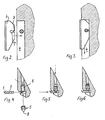
- Figure 2 shows how the cutting blade 1 is inserted into the slot 4 in the knife holder 2.
- Figure 3 shows the cutting blade 1 inserted in the slot 4 in the knife holder 2 and indicates how the screw 5 engaging the circular hole 7 with the conical tip 8 of the screw 5 will press the cutting blade 1 against the bottom of the slot 4.
- Figure 4 shows how the screw 5 is introduced into the knife holder 2 from the backside of the wing into the threaded bore 6, the engagement means on the screw 5 for a tool being positioned against the front side of the wing.
- the screw 5 is screwed into the threaded bore 6 by means of a tool, until the screw 5 engages the bottom of the threaded bore, as shown in Figure 6.
- the cutting blade 1 is inserted into the slot 4, the insertion slot 9 in the cutting blade 1 admitting the cutting blade 1 to move past the conical tip 8 of the screw 5, when the screw 5 is positioned completely screwed in, as shown in Figure 6.
- the screw 5 is tightened, as shown in Figure 5, until the conical tip 8 of the screw 5 engages the circular hole 7 at the back of the insertion slot 9 in the cutting blade 1.
- the circular hole 7 is positioned excentrically with respect to the threaded bore 6, when the cutting blade 1 is positioned as shown in Figure 3, the excentricity being adapted in such a way that the conical tip 8 of the screw 5 wedges the cutting blade 1 against the bottom of the slot 4 in the knife holder 2 tightening the screw 5 to the position shown in Figure 5.
- the embodiment of the arrangement in accordance with the invention shown provides several advantages compared to prior known securing arrangements.
- the screw 5 is prevented from falling out of the knife holder 2, being stopped at one end by the bottom of the threaded bore 6 and at the other end by the cutting blade 1.
- the screw 5 is released and mixed into the meat product, which is to be minced by means of the meat mincing machine.
- the cutting blade 1 is prevented from being thrown out of the knife holder 2, even if the screw 5 is loosened, the screw 5 not being able to move further backwards in the threaded bore than to the bottom of the threaded bore, whereby the conical tip 8 of the screw 5 is still engaged in the circular hole 7 in the cutting blade 1 and thus preventing the cutting blade 1 from moving in a radial direction influenced by the centrifugal force by the rotation of the knife holder 2.
Landscapes
- Engineering & Computer Science (AREA)
- Food Science & Technology (AREA)
- Crushing And Pulverization Processes (AREA)
Description
- The present invention relates to an arrangement for securing a replaceable cutting blade on a rotating knife holder in a cutting assembly for a meat mincing machine. The cutting assembly comprises in the usual way at least one stationary perforated disc and a rotating knife having a blade rotating along the surface of the perforated disc.
- Mounting arrangements are known, comprising at least one slot in the knife holder, adapted to the thickness of the cutting blade in such a way that the replaceable blade can be positioned in the slot and thereby partly be fixed in the knife holder. Usually, further means are needed in order to secure the replaceable cutting blades radially in the knife holder, which e.g. is done by placing a securing ring radially externally of the cutting blades, or, as shown in US-1,033,001, by means of a screw.
- From US-2,259,623 it is known to mount the replaceable blade in a slot provided in the knife holder, and to secure the cutting blade against the bottom of the slot by means of a screw, inserted in a threaded bore extending traversely of the blade through the knife holder, the screw having a conical tip for engaging a hole in the blade. In this construction, there is a risk that the screw and blade fall out of the knife holder, whereby they are mixed with the product and possibly damage the cutting assembly or other parts of the machinery.
- It is the object of the present invention to provide an improved arrangement of the above-mentioned type, whereby the above-mentioned inconveniencies are ameliorated without unnecessarily impeding the replacement of the replaceable cutting blades.
- According to the invention, this is achieved by an arrangement of the above-mentioned kind, which according to the present invention also comprises the features set forth in the characterizing clause of claim 1.
- Preferred embodiments of the invention are revealed in
claims 2 and 3. - The invention will be described further in the following with reference to the drawing, in which
- Figure 1 shows an exploded view of an embodiment of an arrangement in accordance with the invention,
- Figure 2 shows a partial cross section along the slot in a knife holder in accordance with the invention and a cutting blade for mounting in this slot,
- Figure 3 shows a cross section corresponding to Figure 2, in which the cutting blade is mounted in the slot,
- Figure 4 shows a cross section of a knife holder corresponding to the knife holder in Figure 1, 2 and 3, in a plane extending traversely of the slot for the cutting blade and parallel to the direction of the threaded bore, and a cutting blade and screw, not yet mounted,
- Figure 5 shows a cross section corresponding to Figure 4, in which the cutting blade and the screw have been mounted and tightened, and
- Figure 6 shows a cross section corresponding to Figure 4 and 5, in which the cutting blade has been mounted, but the screw is not yet tightened.
-
- The embodiment of the arrangement for securing a replaceable cutting blade 1 on a rotating
knife holder 2 in a cutting assembly in a meat mincing machine, shown in Figure 1, is formed with aknife holder 2 with three wings, each wing being provided with aslot 4 for partially securing a cutting blade 1 in each of the wings. The rotatingknife holder 2 is designed to rotate along the surface of a stationary perforated disc 3, the cutting edge of the cutting blade 1 positioned in short distance from the perforated disc 3. Usually, the cutting assembly, as shown in Figure 1, is used at the end of a transport screw in a meat mincing machine and the rotatingknife holder 2 is rotated in unison with the transport screw by means of the engagement between these, which is provided by the hexagon-formed hole in the rotatingknife holder 2 shown in Figure 1. - The preferred embodiment of the cutting blade 1 shown in Figure 2 is provided with a keyhole-formed cut-out 7,9 comprising a circular hole 7 and an insertion slot 9, which makes it possible to insert the cutting blade 1 in the
slot 4, when the screw 5 is positioned in a position, as shown in Figure 6. Figure 2 shows how the cutting blade 1 is inserted into theslot 4 in theknife holder 2. - Figure 3 shows the cutting blade 1 inserted in the
slot 4 in theknife holder 2 and indicates how the screw 5 engaging the circular hole 7 with theconical tip 8 of the screw 5 will press the cutting blade 1 against the bottom of theslot 4. - Figure 4 shows how the screw 5 is introduced into the
knife holder 2 from the backside of the wing into the threaded bore 6, the engagement means on the screw 5 for a tool being positioned against the front side of the wing. The screw 5 is screwed into the threaded bore 6 by means of a tool, until the screw 5 engages the bottom of the threaded bore, as shown in Figure 6. Then the cutting blade 1 is inserted into theslot 4, the insertion slot 9 in the cutting blade 1 admitting the cutting blade 1 to move past theconical tip 8 of the screw 5, when the screw 5 is positioned completely screwed in, as shown in Figure 6. Then the screw 5 is tightened, as shown in Figure 5, until theconical tip 8 of the screw 5 engages the circular hole 7 at the back of the insertion slot 9 in the cutting blade 1. - Preferably, the circular hole 7 is positioned excentrically with respect to the threaded bore 6, when the cutting blade 1 is positioned as shown in Figure 3, the excentricity being adapted in such a way that the
conical tip 8 of the screw 5 wedges the cutting blade 1 against the bottom of theslot 4 in theknife holder 2 tightening the screw 5 to the position shown in Figure 5. - The embodiment of the arrangement in accordance with the invention shown provides several advantages compared to prior known securing arrangements. The screw 5 is prevented from falling out of the
knife holder 2, being stopped at one end by the bottom of the threaded bore 6 and at the other end by the cutting blade 1. Thus, there is no danger that the screw 5 is released and mixed into the meat product, which is to be minced by means of the meat mincing machine. - The cutting blade 1 is prevented from being thrown out of the
knife holder 2, even if the screw 5 is loosened, the screw 5 not being able to move further backwards in the threaded bore than to the bottom of the threaded bore, whereby theconical tip 8 of the screw 5 is still engaged in the circular hole 7 in the cutting blade 1 and thus preventing the cutting blade 1 from moving in a radial direction influenced by the centrifugal force by the rotation of theknife holder 2. - Although the invention has been explained in the foregoing in connection with a specific embodiment, it is clear that the invention is not limited to this single embodiment, several variations being possible within the scope of the appended claims, such as a variation of the number of wings on the
knife holder 2, the form of the cut-out 7; 7,9 and the insertion slot 9 in the cutting blade 1, etc.
Claims (3)
- Arrangement for securing a replaceable cutting blade (1) on a rotating knife holder (2) in a cutting assembly in a meat mincing machine, in which the cutting blade (1) of the rotating knife holder (2) rotates along the surface of a perforated disc (3), said arrangement comprising the formation of securing features on the cutting blade (1), the rotating knife holder (2) and a screw (5), the securing arrangement comprising at least one slot (4) adapted to the thickness of the cutting blade (1), formed in the knife holder (2) in such a way that the replaceable cutting blade (1) can be positioned in the slot (4), and a screw (5) positioned in a threaded bore (6) formed in the knife holder (2), the threaded bore extending transversely of the slot (4) in such a way that the screw (5) can be moved in the threaded bore (2) to engagement with a cutting blade (1) inserted in the slot (4), for completely securing the cutting blade (1) in the knife holder (2), the cutting blade (1) comprising a cut-out (7; 7,9), preferably a circular hole (7), for engagement with a conical tip (8) of the screw (5), the cut-out (7; 7,9) being formed and placed in such a way that the cutting blade (1) by engagement with the conical tip (8) is wedged against the bottom of the slot (4), characterized in that the threaded bore (6) is formed as a blind hole with a through-going bore at the bottom of the threaded bore, the through-going hole having a diameter, which is smaller than the diameter of the screw (5), the through-going hole permitting insertion of a tool to tighten the screw (5) for completely securing the cutting blade (1) in the knife holder (2).
- Arrangement in accordance with claim 1, characterized by the cutting blade (1) further comprising an insertion slot (9), admitting manual detachment and insertion of the cutting blade (1) in the slot (4), when the screw (5) is loosened, but still protruding into the slot (4).
- Arrangement in accordance with claim 2, characterized in that the position of the bottom of the blind hole is adapted to the length of the screw (5) in such a way that when the screw (5) is inserted into the threaded bore (6) and screwed to engagement against the bottom of the blind hole, the conical tip (8) of the screw (5) is protruding into the slot (4) for partially securing the cutting blade (1).
Applications Claiming Priority (2)
| Application Number | Priority Date | Filing Date | Title |
|---|---|---|---|
| DK68897 | 1997-06-12 | ||
| DK199700688A DK172958B1 (en) | 1997-06-12 | 1997-06-12 | Arrangement for attaching a replaceable cutting blade to a rotary knife holder in a cutting kit for a meat chopper. |
Publications (2)
| Publication Number | Publication Date |
|---|---|
| EP0884106A1 EP0884106A1 (en) | 1998-12-16 |
| EP0884106B1 true EP0884106B1 (en) | 2002-07-10 |
Family
ID=8096408
Family Applications (1)
| Application Number | Title | Priority Date | Filing Date |
|---|---|---|---|
| EP98110119A Expired - Lifetime EP0884106B1 (en) | 1997-06-12 | 1998-06-03 | Arrangement for securing a replaceable cutting blade on a rotating knife holder in a cutting assembly for a meat mincing machine |
Country Status (4)
| Country | Link |
|---|---|
| US (1) | US6029917A (en) |
| EP (1) | EP0884106B1 (en) |
| DE (1) | DE69806448T2 (en) |
| DK (2) | DK172958B1 (en) |
Cited By (1)
| Publication number | Priority date | Publication date | Assignee | Title |
|---|---|---|---|---|
| CN101048066B (en) * | 2004-10-25 | 2012-11-21 | 英诺泰克控股商贸有限两合公司 | Device for producing and processing food |
Families Citing this family (16)
| Publication number | Priority date | Publication date | Assignee | Title |
|---|---|---|---|---|
| DE29911090U1 (en) | 1999-06-25 | 1999-10-07 | Tiromat Krämer + Grebe GmbH & Co. KG, 35216 Biedenkopf | Machine for shredding organic clippings |
| RU2246356C1 (en) * | 2003-08-04 | 2005-02-20 | Федеральное государственное унитарное предприятие "Воронежский механический завод" | Knife |
| RU2297282C1 (en) * | 2005-09-07 | 2007-04-20 | Государственное образовательное учреждение высшего профессионального образования Тульский государственный университет (ТулГУ) | Meat product grinding knife |
| RU2338594C1 (en) * | 2007-01-23 | 2008-11-20 | Государственное образовательное учреждение высшего профессионального образования Санкт-Петербургский государственный университет низкотемпературных и пищевых технологий | Blade cutter for facility for meat foods breakage |
| DE102008019812A1 (en) | 2008-04-19 | 2009-10-22 | Turbocut Jopp Gmbh | Cutter for a meat mincer, with a number of arms, has radial grooves in the arms with the cutting blades held in place in a force or positive fit to prevent movement |
| US8257148B1 (en) | 2009-01-06 | 2012-09-04 | Reliance Controls Corporation | Knife insert with bottom edge relief for cutting edge alignment |
| EP2971520B1 (en) | 2013-03-15 | 2022-02-23 | Pentair Pump Group, Inc. | Cutting blade assembly |
| ITRM20130191A1 (en) * | 2013-04-03 | 2014-10-04 | Evoluzione Srl | ADJUSTABLE CUTTING KNIFE. |
| EP3449130B1 (en) | 2016-04-26 | 2022-11-09 | Pentair Flow Technologies, LLC | Cutting assembly for a chopper pump |
| US10639640B2 (en) * | 2017-10-23 | 2020-05-05 | MedReleaf Corp. | Apparatus and methods for the comminution of botanical feedstock |
| US12016493B2 (en) | 2020-12-31 | 2024-06-25 | Sharkninja Operating Llc | Micro puree machine |
| US11871765B2 (en) | 2020-12-31 | 2024-01-16 | Sharkninja Operating Llc | Micro puree machine |
| USD983603S1 (en) | 2020-12-31 | 2023-04-18 | Sharkninja Operating Llc | Blade for a micro puree machine |
| US12016496B2 (en) | 2020-12-31 | 2024-06-25 | Sharkninja Operating Llc | Micro puree machine |
| US12064056B2 (en) | 2020-12-31 | 2024-08-20 | Sharkninja (Hong Kong) Company Limited | Micro puree machine |
| US11925298B2 (en) | 2020-12-31 | 2024-03-12 | Sharkninja Operating Llc | Micro puree machine |
Family Cites Families (7)
| Publication number | Priority date | Publication date | Assignee | Title |
|---|---|---|---|---|
| DE118745C (en) * | ||||
| US1033001A (en) * | 1911-11-06 | 1912-07-16 | Philip Ganzhorn | Rotary cutter. |
| US2259623A (en) * | 1940-10-14 | 1941-10-21 | Charles W Dieckmann | Rotary cutter |
| DE802044C (en) * | 1949-09-04 | 1951-02-01 | Ver Beckersche Werkzeugfab | Meat grinder knife with interchangeable blades |
| US5092528A (en) * | 1987-09-24 | 1992-03-03 | Cozzini, Inc. | Meat emulsifying and processing system |
| IT1279636B1 (en) * | 1995-09-21 | 1997-12-16 | Evolution Srl | GRINDING UNIT FOR AN INDUSTRIAL MEAT MINCER |
| US5769340A (en) * | 1997-06-17 | 1998-06-23 | Jean; Cheng-Shu | Positioning device for concave of cone crusher |
-
1997
- 1997-06-12 DK DK199700688A patent/DK172958B1/en not_active IP Right Cessation
-
1998
- 1998-06-03 DK DK98110119T patent/DK0884106T3/en active
- 1998-06-03 EP EP98110119A patent/EP0884106B1/en not_active Expired - Lifetime
- 1998-06-03 DE DE69806448T patent/DE69806448T2/en not_active Expired - Fee Related
- 1998-06-08 US US09/092,996 patent/US6029917A/en not_active Expired - Lifetime
Cited By (1)
| Publication number | Priority date | Publication date | Assignee | Title |
|---|---|---|---|---|
| CN101048066B (en) * | 2004-10-25 | 2012-11-21 | 英诺泰克控股商贸有限两合公司 | Device for producing and processing food |
Also Published As
| Publication number | Publication date |
|---|---|
| US6029917A (en) | 2000-02-29 |
| DK68897A (en) | 1998-12-13 |
| DE69806448T2 (en) | 2003-02-13 |
| EP0884106A1 (en) | 1998-12-16 |
| DE69806448D1 (en) | 2002-08-14 |
| DK0884106T3 (en) | 2002-10-28 |
| DK172958B1 (en) | 1999-10-18 |
Similar Documents
| Publication | Publication Date | Title |
|---|---|---|
| US6029917A (en) | Arrangement for securing a replaceable cutting blade on a rotating knife holder in a cutting assembly for a meat mincing machine | |
| US5027684A (en) | Collar for mounting a split saw blade on an arbor | |
| US7004692B2 (en) | Rotary cutting tool | |
| EP0997218B1 (en) | Rotating cutting tool with a cutting insert | |
| AU2021232665B2 (en) | Knife assemblies for slicing machines and machines equipped therewith | |
| US8534330B2 (en) | Knife and knife assembly for a planer side head | |
| US4936516A (en) | Rotary cutter tool, particularly for shredding plastic materials | |
| US5820042A (en) | Wood chipper rotor head knife holder and knife assembly | |
| US5816301A (en) | Knife supporting structure | |
| US2259623A (en) | Rotary cutter | |
| US3330317A (en) | Meat cutter having adjustable blades | |
| US6447378B1 (en) | Abrasive throwing wheel and abrasive throwing blade | |
| US4907631A (en) | Blade assembly for planer cutter head | |
| JP4897134B2 (en) | Coronal cutter cutting machine for cutting a cutting piece | |
| WO1996006680A1 (en) | A crusher blade assembly | |
| US2657723A (en) | Knife blade mounting for chippers | |
| US6095210A (en) | Woodworking shaper head | |
| KR200307711Y1 (en) | Cutter and bearing fixing device of shredder axis | |
| EP3292967B1 (en) | Cutter and fly-wheel for wood chipping machines | |
| GB2322310A (en) | Shredder | |
| SE501407C2 (en) | Device comprising a body, a member rotatably arranged in the body and a counter-cutting device cooperating therewith, which is arranged on the body | |
| JPH09216202A (en) | Wood processing cutter |
Legal Events
| Date | Code | Title | Description |
|---|---|---|---|
| PUAI | Public reference made under article 153(3) epc to a published international application that has entered the european phase |
Free format text: ORIGINAL CODE: 0009012 |
|
| AK | Designated contracting states |
Kind code of ref document: A1 Designated state(s): DE DK GB NL |
|
| AX | Request for extension of the european patent |
Free format text: AL;LT;LV;MK;RO;SI |
|
| 17P | Request for examination filed |
Effective date: 19990616 |
|
| AKX | Designation fees paid |
Free format text: DE DK GB NL |
|
| 17Q | First examination report despatched |
Effective date: 20010703 |
|
| GRAG | Despatch of communication of intention to grant |
Free format text: ORIGINAL CODE: EPIDOS AGRA |
|
| GRAG | Despatch of communication of intention to grant |
Free format text: ORIGINAL CODE: EPIDOS AGRA |
|
| GRAH | Despatch of communication of intention to grant a patent |
Free format text: ORIGINAL CODE: EPIDOS IGRA |
|
| GRAH | Despatch of communication of intention to grant a patent |
Free format text: ORIGINAL CODE: EPIDOS IGRA |
|
| GRAA | (expected) grant |
Free format text: ORIGINAL CODE: 0009210 |
|
| AK | Designated contracting states |
Kind code of ref document: B1 Designated state(s): DE DK GB NL |
|
| REG | Reference to a national code |
Ref country code: GB Ref legal event code: FG4D |
|
| REF | Corresponds to: |
Ref document number: 69806448 Country of ref document: DE Date of ref document: 20020814 |
|
| REG | Reference to a national code |
Ref country code: DK Ref legal event code: T3 |
|
| NLT1 | Nl: modifications of names registered in virtue of documents presented to the patent office pursuant to art. 16 a, paragraph 1 |
Owner name: WOLFKING A/S Owner name: CFS SLAGELSE A/S |
|
| PLBE | No opposition filed within time limit |
Free format text: ORIGINAL CODE: 0009261 |
|
| STAA | Information on the status of an ep patent application or granted ep patent |
Free format text: STATUS: NO OPPOSITION FILED WITHIN TIME LIMIT |
|
| 26N | No opposition filed |
Effective date: 20030411 |
|
| PGFP | Annual fee paid to national office [announced via postgrant information from national office to epo] |
Ref country code: DK Payment date: 20080623 Year of fee payment: 11 |
|
| PGFP | Annual fee paid to national office [announced via postgrant information from national office to epo] |
Ref country code: NL Payment date: 20080618 Year of fee payment: 11 Ref country code: DE Payment date: 20080827 Year of fee payment: 11 |
|
| PGFP | Annual fee paid to national office [announced via postgrant information from national office to epo] |
Ref country code: GB Payment date: 20080624 Year of fee payment: 11 |
|
| REG | Reference to a national code |
Ref country code: DK Ref legal event code: EBP |
|
| GBPC | Gb: european patent ceased through non-payment of renewal fee |
Effective date: 20090603 |
|
| NLV4 | Nl: lapsed or anulled due to non-payment of the annual fee |
Effective date: 20100101 |
|
| PG25 | Lapsed in a contracting state [announced via postgrant information from national office to epo] |
Ref country code: GB Free format text: LAPSE BECAUSE OF NON-PAYMENT OF DUE FEES Effective date: 20090603 |
|
| PG25 | Lapsed in a contracting state [announced via postgrant information from national office to epo] |
Ref country code: DE Free format text: LAPSE BECAUSE OF NON-PAYMENT OF DUE FEES Effective date: 20100101 |
|
| PG25 | Lapsed in a contracting state [announced via postgrant information from national office to epo] |
Ref country code: NL Free format text: LAPSE BECAUSE OF NON-PAYMENT OF DUE FEES Effective date: 20100101 Ref country code: DK Free format text: LAPSE BECAUSE OF NON-PAYMENT OF DUE FEES Effective date: 20090630 |