EP0883790B1 - Ammunition unit in the form of a shell or the like - Google Patents
Ammunition unit in the form of a shell or the like Download PDFInfo
- Publication number
- EP0883790B1 EP0883790B1 EP97914723A EP97914723A EP0883790B1 EP 0883790 B1 EP0883790 B1 EP 0883790B1 EP 97914723 A EP97914723 A EP 97914723A EP 97914723 A EP97914723 A EP 97914723A EP 0883790 B1 EP0883790 B1 EP 0883790B1
- Authority
- EP
- European Patent Office
- Prior art keywords
- charge
- warhead
- dividing
- ammunition unit
- ignition device
- Prior art date
- Legal status (The legal status is an assumption and is not a legal conclusion. Google has not performed a legal analysis and makes no representation as to the accuracy of the status listed.)
- Expired - Lifetime
Links
- 230000000977 initiatory effect Effects 0.000 claims description 6
- 238000005474 detonation Methods 0.000 claims description 4
- 230000000694 effects Effects 0.000 abstract description 4
- 239000002360 explosive Substances 0.000 description 10
- 239000000463 material Substances 0.000 description 2
- 230000004913 activation Effects 0.000 description 1
- 230000006735 deficit Effects 0.000 description 1
- 238000000926 separation method Methods 0.000 description 1
Images

Classifications
-
- F—MECHANICAL ENGINEERING; LIGHTING; HEATING; WEAPONS; BLASTING
- F42—AMMUNITION; BLASTING
- F42B—EXPLOSIVE CHARGES, e.g. FOR BLASTING, FIREWORKS, AMMUNITION
- F42B12/00—Projectiles, missiles or mines characterised by the warhead, the intended effect, or the material
- F42B12/02—Projectiles, missiles or mines characterised by the warhead, the intended effect, or the material characterised by the warhead or the intended effect
- F42B12/04—Projectiles, missiles or mines characterised by the warhead, the intended effect, or the material characterised by the warhead or the intended effect of armour-piercing type
- F42B12/10—Projectiles, missiles or mines characterised by the warhead, the intended effect, or the material characterised by the warhead or the intended effect of armour-piercing type with shaped or hollow charge
- F42B12/16—Projectiles, missiles or mines characterised by the warhead, the intended effect, or the material characterised by the warhead or the intended effect of armour-piercing type with shaped or hollow charge in combination with an additional projectile or charge, acting successively on the target
Definitions
- the present invention relates to an ammunition unit in the form of a shell or the like, comprising at least one front warhead and one rear warhead, such as, for example, shaped-charge warheads, arranged in succession one after the other and connected to each other via a supporting structure.
- Each one of the warheads included is assigned an ignition device with ignition and safety functions, and the ignition device of the front warhead is arranged in the supporting structure behind the front warhead in the direction of action of a warhead lying to the rear.
- An ammunition unit of the abovementioned type is already known from EP-A-0 238 715, for example.
- the latter involves a small front warhead with shaped charge, the so-called pre-penetrator, and a larger rear warhead with shaped charge, the so-called main charge.
- the object of the present invention is to lessen or to completely prevent the impairment in the efficiency of the ammunition unit caused by the factors mentioned.
- the object of the invention is achieved by means of an ammunition unit characterized in that a structure-dividing charge is arranged in the supporting structure in order to divide the supporting structure into a front part and a rear part after initiation.
- division of the structure is intended to mean everything from narrow cuts to more extensive removal of material in the area where the supporting structure is divided.
- the structure-dividing charge comprises an annular element with an external diameter essentially corresponding to the internal diameter of the supporting structure, and a number of radial channels which connect the inner surface of the annular element to a central point common to the channels.
- This embodiment of the structure-dividing charge has been shown to produce an effective division of the structure without any disruptive effect on the rest of the ammunition unit.
- the annular element is connected to the common centre point by means of two channels directed radially towards each other. The embodiment has been shown to give a symmetrical activation with little effect on warheads situated to the rear.
- the structure-dividing charge comprises a disc-shaped element whose external diameter essentially corresponds to the internal diameter of the supporting structure.
- a structure-dividing charge of this design is, among other things, simple to produce.
- a clearing charge can be arranged in order to clear the ignition device belonging to a forward warhead out of the way.
- the design is characterized in that a clearing charge is linked to the structure-dividing charge in order to clear the ignition member out of the way of a warhead situated to the rear.
- the clearing charge is made up of a curved plate designed to be arranged between the ignition device and the supporting structure and to cover only parts of the circumference of the ignition device.
- the clearing charge is preferably arranged to be ignited by crossover ignition from the structure-dividing charge.
- the structure-dividing charge and the clearing charge can advantageously be designed as one component.
- the initiation of the front warhead, the structure-dividing charge and the clearing charge is effected by means of the ignition device acting at one initiation point common to the warhead and the two charges.
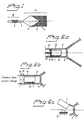
- Figure 1 shows diagrammatically an example of an ammunition unit according to the invention in the form of a tandem shell.
- Figures 2a to 2c show diagrammatically a section through the middle part of the tandem shell according to Figure 1, at three different times during the shell's detonation phase.
- Figures 3a and 3b show, in a front view and cross-sectional side view, respectively, a first example of a structure-dividing charge which can be incorporated in the tandem shell according to Figure 1.
- Figures 4a and 4b show, in a front view and cross-sectional side view, respectively, a second example of a structure-dividing charge which can be incorporated in a tandem shell according to Figure 1.
- Figure 5 shows a perspective view of an example of a clearing charge which can be incorporated in the tandem shell according to Figure 1.
- the ammunition unit shown diagrammatically in Figure 1, is in the form of a shell 1 and comprises a front explosive charge 2, which is incorporated in a front warhead 18, and a rear explosive charge 3, which is incorporated in a rear warhead 19.
- the rear explosive charge 3 consists of a shaped charge with liner 4, while the front charge consists of another type of charge known in the context of tandem shells. However, there is nothing to prevent both charges being of the shaped-charge type.
- the front and rear charges 2, 3 are held together by means of a supporting structure 5 in the middle part of the shell.
- FIG. 2 shows the middle part 5 of the shell in greater detail.
- the supporting structure 5 comprises a tubular part 6 which accommodates, inter alia, the ignition device 7 of the front explosive charge, with ignition members and safety members.
- a corresponding ignition device is arranged behind the rear explosive charge 3.
- the structure-dividing charge 8 Arranged between the ignition device and the front explosive charge there is a structure-dividing charge 8.
- a first example of a structure-dividing charge is shown in Figures 3a and 3b.
- the structure-dividing charge 8 in this case comprises a ring 9 and two radially opposed channels 10, 11 which connect the centre of the ring to the ring.
- the external diameter of the ring is dimensioned so as to correspond essentially to the internal diameter of the tubular structure 5.
- the structure-dividing charge 8 comprises a ring 9 and a disc 21.
- the ring 9 and the disc 21 can be designed as one unit.
- the external diameter of the ring is dimensioned to correspond essentially to the internal diameter of the tubular structure 5.
- a clearing charge 12 Arranged in the space between the ignition device 7 and the tubular structure 5 there is a clearing charge 12.
- the clearing charge has the shape of a curved plate, see in particular Figure 5, which plate covers parts of the circumference of the ignition device.
- the clearing charge 12 is separated from the structure-dividing charge 8 by means of an air gap 13 which is dimensioned so that crossover ignition of the clearing charge can be effected from the structure-dividing charge.
- the clearing charge 12 and the structure-dividing charge 8 can be arranged in direct connection to each other or can even be designed as one single-piece component.
- a suitable material for the clearing charge and the structure-dividing charge is a compressible explosive, for example of the plastic-based type.
- the clearing charge 12 can be arranged in the ignition device 7 and, according to another embodiment, on the outside of the structure 5.
- the ignition members in the ignition device 7 act at one initiation point 17, common to the front explosive charge 2, the structure-dividing charge 8 and the clearing charge 12, at the centre of the ring 9, which is included in the structure-dividing charge 8.
- the structure-dividing charge 8 detonates and divides the structure 5 into a front part 14 and a rear part 15 separated by an intermediate air space 16.
- the intermediate air space 16 can be obtained by means of comparatively large or small parts of the structure being blasted away in the vicinity of the structure-dividing charge 8.
- the structure-dividing charge can also effect a certain separation in the longitudinal direction between the front and rear parts of the structure.
- the front charge 2 detonates slightly later.
- the intermediate air space 16 which has been formed, the impact from the front charge 2 is prevented from reaching the charge 3 lying to the rear.
- crossover ignition to the clearing charge 12 takes place with a certain delay.
- the rear part of the tubular structure is broken open, as indicated in Figure 2c, and the ignition device 7 is caused to leave the area in front of the remaining explosive charge 3. Free space is in this way made available to allow the remaining explosive charge to develop its shaped-charge jet without disruption.
- the clearing charge 12 can be used to transmit a detonation which in turn can ignite, for example, a charge situated to the rear.
Landscapes
- Engineering & Computer Science (AREA)
- Chemical & Material Sciences (AREA)
- Combustion & Propulsion (AREA)
- General Engineering & Computer Science (AREA)
- Automotive Seat Belt Assembly (AREA)
- Tents Or Canopies (AREA)
- Air Bags (AREA)
- Emergency Lowering Means (AREA)
- Management, Administration, Business Operations System, And Electronic Commerce (AREA)
- Acyclic And Carbocyclic Compounds In Medicinal Compositions (AREA)
- Looms (AREA)
- Forms Removed On Construction Sites Or Auxiliary Members Thereof (AREA)
- Buildings Adapted To Withstand Abnormal External Influences (AREA)
Abstract
Description
- The present invention relates to an ammunition unit in the form of a shell or the like, comprising at least one front warhead and one rear warhead, such as, for example, shaped-charge warheads, arranged in succession one after the other and connected to each other via a supporting structure. Each one of the warheads included is assigned an ignition device with ignition and safety functions, and the ignition device of the front warhead is arranged in the supporting structure behind the front warhead in the direction of action of a warhead lying to the rear.
- An ammunition unit of the abovementioned type is already known from EP-A-0 238 715, for example. The latter involves a small front warhead with shaped charge, the so-called pre-penetrator, and a larger rear warhead with shaped charge, the so-called main charge.
- In ammunition units of this known type, there are a number of factors which can radically impair the efficiency of the ammunition unit. One such factor is the impact which the first activated warhead generates and which propagates through to the remaining and not yet activated warheads. The impact can damage warheads situated to the rear or disrupt them such that they do not interact with the first warhead in the manner intended. The impact problem is aggravated especially when the front warhead is made larger. Another factor impairing efficiency is the disruptive influence which the ignition device of the front warhead has on a shaped-charge jet coming from the rear.
- The object of the present invention is to lessen or to completely prevent the impairment in the efficiency of the ammunition unit caused by the factors mentioned. The object of the invention is achieved by means of an ammunition unit characterized in that a structure-dividing charge is arranged in the supporting structure in order to divide the supporting structure into a front part and a rear part after initiation. In this context, division of the structure is intended to mean everything from narrow cuts to more extensive removal of material in the area where the supporting structure is divided. By dividing the structure, the impact from the front warhead is prevented from reaching warheads situated to the rear. At the same time, parts of the ignition device are also exposed.
- According to one advantageous embodiment, the structure-dividing charge comprises an annular element with an external diameter essentially corresponding to the internal diameter of the supporting structure, and a number of radial channels which connect the inner surface of the annular element to a central point common to the channels. This embodiment of the structure-dividing charge has been shown to produce an effective division of the structure without any disruptive effect on the rest of the ammunition unit. According to a specific embodiment based on this annular design, the annular element is connected to the common centre point by means of two channels directed radially towards each other. The embodiment has been shown to give a symmetrical activation with little effect on warheads situated to the rear.
- According to another advantageous embodiment, the structure-dividing charge comprises a disc-shaped element whose external diameter essentially corresponds to the internal diameter of the supporting structure. A structure-dividing charge of this design is, among other things, simple to produce.
- For improving the efficiency of the ammunition unit still further, according to yet another advantageous embodiment a clearing charge can be arranged in order to clear the ignition device belonging to a forward warhead out of the way. The design is characterized in that a clearing charge is linked to the structure-dividing charge in order to clear the ignition member out of the way of a warhead situated to the rear. In one expedient design, the clearing charge is made up of a curved plate designed to be arranged between the ignition device and the supporting structure and to cover only parts of the circumference of the ignition device.
- The clearing charge is preferably arranged to be ignited by crossover ignition from the structure-dividing charge. In this case, the structure-dividing charge and the clearing charge can advantageously be designed as one component.
- In a simple and operationally reliable design, the initiation of the front warhead, the structure-dividing charge and the clearing charge is effected by means of the ignition device acting at one initiation point common to the warhead and the two charges.
- The invention will be described in greater detail below with reference to the attached drawings, in which:
- Figure 1 shows diagrammatically an example of an ammunition unit according to the invention in the form of a tandem shell.
- Figures 2a to 2c show diagrammatically a section through the middle part of the tandem shell according to Figure 1, at three different times during the shell's detonation phase.
- Figures 3a and 3b show, in a front view and cross-sectional side view, respectively, a first example of a structure-dividing charge which can be incorporated in the tandem shell according to Figure 1.
- Figures 4a and 4b show, in a front view and cross-sectional side view, respectively, a second example of a structure-dividing charge which can be incorporated in a tandem shell according to Figure 1.
- Figure 5 shows a perspective view of an example of a clearing charge which can be incorporated in the tandem shell according to Figure 1.
- The ammunition unit, shown diagrammatically in Figure 1, is in the form of a shell 1 and comprises a front
explosive charge 2, which is incorporated in afront warhead 18, and a rearexplosive charge 3, which is incorporated in arear warhead 19. In the case shown here, the rearexplosive charge 3 consists of a shaped charge withliner 4, while the front charge consists of another type of charge known in the context of tandem shells. However, there is nothing to prevent both charges being of the shaped-charge type. The front andrear charges structure 5 in the middle part of the shell. - Figure 2 shows the
middle part 5 of the shell in greater detail. The supportingstructure 5 comprises atubular part 6 which accommodates, inter alia, theignition device 7 of the front explosive charge, with ignition members and safety members. In this context, it is worth noting that a corresponding ignition device, not shown, is arranged behind the rearexplosive charge 3. - Arranged between the ignition device and the front explosive charge there is a structure-dividing
charge 8. A first example of a structure-dividing charge is shown in Figures 3a and 3b. The structure-dividingcharge 8 in this case comprises aring 9 and two radiallyopposed channels tubular structure 5. - According to a second example of a structure-dividing charge, shown in Figures 4a and 4b, the structure-dividing
charge 8 comprises aring 9 and adisc 21. Thering 9 and thedisc 21 can be designed as one unit. As in the design described with reference to Figures 3a and 3b, the external diameter of the ring is dimensioned to correspond essentially to the internal diameter of thetubular structure 5. - Arranged in the space between the
ignition device 7 and thetubular structure 5 there is aclearing charge 12. In the design shown here, the clearing charge has the shape of a curved plate, see in particular Figure 5, which plate covers parts of the circumference of the ignition device. Theclearing charge 12 is separated from the structure-dividingcharge 8 by means of anair gap 13 which is dimensioned so that crossover ignition of the clearing charge can be effected from the structure-dividing charge. Alternatively, theclearing charge 12 and the structure-dividingcharge 8 can be arranged in direct connection to each other or can even be designed as one single-piece component. A suitable material for the clearing charge and the structure-dividing charge is a compressible explosive, for example of the plastic-based type. - A number of alternative positions are possible for the
clearing charge 12. For example, according to one embodiment, theclearing charge 12 can be arranged in theignition device 7 and, according to another embodiment, on the outside of thestructure 5. - The ignition members in the
ignition device 7 act at one initiation point 17, common to the frontexplosive charge 2, the structure-dividingcharge 8 and theclearing charge 12, at the centre of thering 9, which is included in the structure-dividingcharge 8. - Upon initiation from the
ignition device 7, the sequence of events which is shown in Figures 2b and 2c takes place. - In a first stage, the structure-dividing
charge 8 detonates and divides thestructure 5 into afront part 14 and arear part 15 separated by anintermediate air space 16. Theintermediate air space 16 can be obtained by means of comparatively large or small parts of the structure being blasted away in the vicinity of the structure-dividingcharge 8. The structure-dividing charge can also effect a certain separation in the longitudinal direction between the front and rear parts of the structure. - The
front charge 2 detonates slightly later. By virtue of theintermediate air space 16 which has been formed, the impact from thefront charge 2 is prevented from reaching thecharge 3 lying to the rear. When the structure-dividingcharge 8 detonates, crossover ignition to theclearing charge 12 takes place with a certain delay. Upon detonation of the clearing charge, the rear part of the tubular structure is broken open, as indicated in Figure 2c, and theignition device 7 is caused to leave the area in front of the remainingexplosive charge 3. Free space is in this way made available to allow the remaining explosive charge to develop its shaped-charge jet without disruption. - During the sequence of events described above, the
clearing charge 12 can be used to transmit a detonation which in turn can ignite, for example, a charge situated to the rear.
Claims (8)
- Ammunition unit (1) in the form of a shell or the like, comprising at least one front warhead (18) and one rear warhead (19), such as, for example, shaped-charge warheads, arranged in succession one after the other and connected to each other via a supporting structure (5), in which each one of the warheads (18, 19) included is assigned an ignition device (7) with ignition and safety functions, and the ignition device (7) of the front warhead (18) is arranged in the supporting structure (5) behind the front warhead (18) in the direction of action of a warhead (19) lying to the rear, characterized in that a structure-dividing charge (8) is arranged in the supporting structure (5) in order to divide the supporting structure into a front part (14) and a rear part (15) after initiation.
- Ammunition unit according to Claim 1, characterized in that the structure-dividing charge (8) comprises a disc-shaped element (21) whose external diameter essentially corresponds to the internal diameter of the supporting structure (5).
- Ammunition unit according to Claim 1, characterized in that the structure-dividing charge (8) comprises an annular element (9) with an external diameter essentially corresponding to the internal diameter of the supporting structure, and a number of radial channels (10, 11) which connect the inner surface of the annular element to a central point common to the channels.
- Ammunition unit according to Claim 3, characterized in that the annular element (9) is connected to the common centre point by means of two channels (10, 11) directed radially towards each other.
- Ammunition unit according to any of the preceding claims, characterized in that a clearing charge (12) is linked to the structure-dividing charge (8) in order to clear the ignition device (7) out of the way of a warhead (19) lying to the rear.
- Ammunition unit according to Claim 5, characterized in that the clearing charge (12) is made up of a curved plate designed to be arranged between the ignition device (7) and the supporting structure (5) and to cover only parts of the circumference of the ignition device.
- Ammunition unit according to either of preceding claims 5 - 6, characterized in that the structure-dividing charge (8) and the clearing charge (12) are designed as one component.
- Ammunition unit according to any of the preceding claims, characterized in that the structure-dividing charge (8), the clearing charge (12) and the warhead at the front are provided with one detonation point common to the ignition device (7).
Applications Claiming Priority (3)
| Application Number | Priority Date | Filing Date | Title |
|---|---|---|---|
| SE9601114A SE505188C2 (en) | 1996-03-22 | 1996-03-22 | Ammunition device in the form of grenade or similar |
| SE9601114 | 1996-03-22 | ||
| PCT/SE1997/000460 WO1997035157A1 (en) | 1996-03-22 | 1997-03-20 | Ammunition unit in the form of a shell or the like |
Publications (2)
| Publication Number | Publication Date |
|---|---|
| EP0883790A1 EP0883790A1 (en) | 1998-12-16 |
| EP0883790B1 true EP0883790B1 (en) | 2001-11-28 |
Family
ID=20401910
Family Applications (1)
| Application Number | Title | Priority Date | Filing Date |
|---|---|---|---|
| EP97914723A Expired - Lifetime EP0883790B1 (en) | 1996-03-22 | 1997-03-20 | Ammunition unit in the form of a shell or the like |
Country Status (7)
| Country | Link |
|---|---|
| US (1) | US6032583A (en) |
| EP (1) | EP0883790B1 (en) |
| DE (1) | DE69708608T2 (en) |
| ES (1) | ES2166072T3 (en) |
| NO (1) | NO317749B1 (en) |
| SE (1) | SE505188C2 (en) |
| WO (1) | WO1997035157A1 (en) |
Families Citing this family (2)
| Publication number | Priority date | Publication date | Assignee | Title |
|---|---|---|---|---|
| ES2385040T3 (en) * | 2005-07-01 | 2012-07-17 | Saab Ab | Ammo piece with kinetic precursor |
| DE102020001784A1 (en) | 2020-03-17 | 2021-09-23 | Diehl Defence Gmbh & Co. Kg | Projectile, device arrangement and method |
Family Cites Families (12)
| Publication number | Priority date | Publication date | Assignee | Title |
|---|---|---|---|---|
| FR493294A (en) * | 1916-03-01 | 1919-08-05 | Joseph Paonessa | Repeating shells |
| GB1051407A (en) * | 1964-07-08 | 1966-12-14 | Director General Of Fírsvarets Fabriksstyrelse. | Improvements in or relating to High-explosive Armour piercing Shells |
| FR2385074A1 (en) * | 1977-03-23 | 1978-10-20 | Haut Rhin Manufacture Machines | Anti-personnel rocket multiple explosive charge - has propulsive charge, scatter charge with detonator and impact charge with detonator |
| DE3004047C2 (en) * | 1980-02-05 | 1984-10-31 | Rheinmetall GmbH, 4000 Düsseldorf | Armor-piercing projectile |
| FR2552870B1 (en) * | 1980-10-24 | 1987-02-13 | France Etat Armement | IMPROVEMENT FOR MILITARY HEADS WITH FORMED LOADS MOUNTED IN TANDEM |
| DE3336853A1 (en) * | 1983-10-11 | 1985-04-25 | Rheinmetall GmbH, 4000 Düsseldorf | MULTIPURPOSE HEAD |
| FR2559896B1 (en) * | 1984-02-20 | 1987-09-25 | France Etat Armement | DELAY INITIATION FOR MILITARY HEAD WITH FORMED LOADS MOUNTED IN TANDEM |
| DE3605580C1 (en) * | 1986-02-21 | 1987-06-04 | Messerschmitt Boelkow Blohm | Warhead |
| GB8620138D0 (en) * | 1986-08-19 | 1994-01-26 | British Aerospace | Projectile warhead |
| IL81097A (en) * | 1986-12-25 | 1991-06-10 | Israel Defence | Two-stage shaped charge projectile |
| US5107766A (en) * | 1991-07-25 | 1992-04-28 | Schliesske Harold R | Follow-thru grenade for military operations in urban terrain (MOUT) |
| US5698814A (en) * | 1995-03-10 | 1997-12-16 | The United States Of America As Represented By The Secretary Of The Air Force | Hard target penetrator with multi-segmenting casing cutter |
-
1996
- 1996-03-22 SE SE9601114A patent/SE505188C2/en not_active IP Right Cessation
-
1997
- 1997-03-20 DE DE69708608T patent/DE69708608T2/en not_active Expired - Lifetime
- 1997-03-20 US US09/125,948 patent/US6032583A/en not_active Expired - Lifetime
- 1997-03-20 ES ES97914723T patent/ES2166072T3/en not_active Expired - Lifetime
- 1997-03-20 WO PCT/SE1997/000460 patent/WO1997035157A1/en not_active Ceased
- 1997-03-20 EP EP97914723A patent/EP0883790B1/en not_active Expired - Lifetime
-
1998
- 1998-09-21 NO NO19984396A patent/NO317749B1/en not_active IP Right Cessation
Also Published As
| Publication number | Publication date |
|---|---|
| DE69708608T2 (en) | 2002-08-08 |
| NO984396L (en) | 1998-09-21 |
| SE9601114L (en) | 1997-07-14 |
| DE69708608D1 (en) | 2002-01-10 |
| NO317749B1 (en) | 2004-12-13 |
| SE505188C2 (en) | 1997-07-14 |
| ES2166072T3 (en) | 2002-04-01 |
| WO1997035157A1 (en) | 1997-09-25 |
| US6032583A (en) | 2000-03-07 |
| NO984396D0 (en) | 1998-09-21 |
| EP0883790A1 (en) | 1998-12-16 |
Similar Documents
| Publication | Publication Date | Title |
|---|---|---|
| US4026213A (en) | Selectively aimable warhead | |
| AU596749B2 (en) | Improved perforating projectile | |
| US4665826A (en) | Hybrid explosive unit | |
| US5594197A (en) | Secondary projectile for a tandem warhead | |
| RU98102124A (en) | STEM SET WITH ACCESSORIES PLACED ON ITS AXIS | |
| US4854240A (en) | Two-stage shaped charge projectile | |
| US5042388A (en) | Forward control tube with sequenced ignition | |
| US4503773A (en) | Aft end igniter for full, head-end web solid propellant rocket motors | |
| CA2159343C (en) | A method and an apparatus for spreading warheads | |
| US5347907A (en) | Multipurpose projectile and a method of making it | |
| CH635422A5 (en) | EXPLOSIVE CHARGE. | |
| US6032583A (en) | Ammunition unit in the form of a shell | |
| EP1634034A1 (en) | Device adjacent to an explosive charge with at least two liners | |
| US5952604A (en) | Shell with multi-charges | |
| US6283032B1 (en) | Projectile with controlled decomposition and integrated charge in the area of the effective mass | |
| WO2004070311A2 (en) | Double explosively-formed ring (defr) warhead | |
| ES8308632A1 (en) | Safety device for a projectile | |
| US5796030A (en) | Mine | |
| CA2155399C (en) | Spin-stabilized projectile with a payload | |
| KR20030090667A (en) | Igniter with a safety device for a projectile which is shot from a pipe with angular momentum | |
| RU97114855A (en) | Shell | |
| RU95107279A (en) | Charging device to gunshot | |
| US5050502A (en) | Ammunition unit having a sleeve on a primer tube | |
| ZA200309596B (en) | Ammunition device with two active charges | |
| RU2244243C1 (en) | Shaped charge |
Legal Events
| Date | Code | Title | Description |
|---|---|---|---|
| PUAI | Public reference made under article 153(3) epc to a published international application that has entered the european phase |
Free format text: ORIGINAL CODE: 0009012 |
|
| 17P | Request for examination filed |
Effective date: 19981006 |
|
| AK | Designated contracting states |
Kind code of ref document: A1 Designated state(s): CH DE DK ES FI FR GB LI NL |
|
| RIN1 | Information on inventor provided before grant (corrected) |
Inventor name: LINDVALL, RICHARD Inventor name: ANDERSSON, PAER Inventor name: BENENDO, MIROSLAW Inventor name: SJOEOE, LENNART Inventor name: HELANDER, JYRKI Inventor name: KARLSTEDT, GUSTAV |
|
| 17Q | First examination report despatched |
Effective date: 20000119 |
|
| GRAG | Despatch of communication of intention to grant |
Free format text: ORIGINAL CODE: EPIDOS AGRA |
|
| GRAG | Despatch of communication of intention to grant |
Free format text: ORIGINAL CODE: EPIDOS AGRA |
|
| GRAH | Despatch of communication of intention to grant a patent |
Free format text: ORIGINAL CODE: EPIDOS IGRA |
|
| RAP1 | Party data changed (applicant data changed or rights of an application transferred) |
Owner name: SAAB AB |
|
| GRAH | Despatch of communication of intention to grant a patent |
Free format text: ORIGINAL CODE: EPIDOS IGRA |
|
| GRAA | (expected) grant |
Free format text: ORIGINAL CODE: 0009210 |
|
| AK | Designated contracting states |
Kind code of ref document: B1 Designated state(s): CH DE DK ES FI FR GB LI NL |
|
| PG25 | Lapsed in a contracting state [announced via postgrant information from national office to epo] |
Ref country code: NL Free format text: LAPSE BECAUSE OF FAILURE TO SUBMIT A TRANSLATION OF THE DESCRIPTION OR TO PAY THE FEE WITHIN THE PRESCRIBED TIME-LIMIT Effective date: 20011128 Ref country code: FI Free format text: LAPSE BECAUSE OF FAILURE TO SUBMIT A TRANSLATION OF THE DESCRIPTION OR TO PAY THE FEE WITHIN THE PRESCRIBED TIME-LIMIT Effective date: 20011128 |
|
| REG | Reference to a national code |
Ref country code: CH Ref legal event code: EP |
|
| REG | Reference to a national code |
Ref country code: GB Ref legal event code: IF02 |
|
| REF | Corresponds to: |
Ref document number: 69708608 Country of ref document: DE Date of ref document: 20020110 |
|
| REG | Reference to a national code |
Ref country code: CH Ref legal event code: NV Representative=s name: E. BLUM & CO. PATENTANWAELTE |
|
| PG25 | Lapsed in a contracting state [announced via postgrant information from national office to epo] |
Ref country code: DK Free format text: LAPSE BECAUSE OF FAILURE TO SUBMIT A TRANSLATION OF THE DESCRIPTION OR TO PAY THE FEE WITHIN THE PRESCRIBED TIME-LIMIT Effective date: 20020228 |
|
| ET | Fr: translation filed | ||
| PG25 | Lapsed in a contracting state [announced via postgrant information from national office to epo] |
Ref country code: GB Free format text: LAPSE BECAUSE OF NON-PAYMENT OF DUE FEES Effective date: 20020320 |
|
| REG | Reference to a national code |
Ref country code: ES Ref legal event code: FG2A Ref document number: 2166072 Country of ref document: ES Kind code of ref document: T3 |
|
| NLV1 | Nl: lapsed or annulled due to failure to fulfill the requirements of art. 29p and 29m of the patents act | ||
| PLBE | No opposition filed within time limit |
Free format text: ORIGINAL CODE: 0009261 |
|
| STAA | Information on the status of an ep patent application or granted ep patent |
Free format text: STATUS: NO OPPOSITION FILED WITHIN TIME LIMIT |
|
| GBPC | Gb: european patent ceased through non-payment of renewal fee |
Effective date: 20020320 |
|
| 26N | No opposition filed | ||
| PGFP | Annual fee paid to national office [announced via postgrant information from national office to epo] |
Ref country code: CH Payment date: 20070314 Year of fee payment: 11 |
|
| REG | Reference to a national code |
Ref country code: CH Ref legal event code: PFA Owner name: SAAB AB Free format text: SAAB AB# #581 88 LINKOEPING (SE) -TRANSFER TO- SAAB AB# #581 88 LINKOEPING (SE) |
|
| REG | Reference to a national code |
Ref country code: CH Ref legal event code: PL |
|
| PG25 | Lapsed in a contracting state [announced via postgrant information from national office to epo] |
Ref country code: LI Free format text: LAPSE BECAUSE OF NON-PAYMENT OF DUE FEES Effective date: 20080331 Ref country code: CH Free format text: LAPSE BECAUSE OF NON-PAYMENT OF DUE FEES Effective date: 20080331 |
|
| REG | Reference to a national code |
Ref country code: FR Ref legal event code: PLFP Year of fee payment: 20 |
|
| PGFP | Annual fee paid to national office [announced via postgrant information from national office to epo] |
Ref country code: ES Payment date: 20160328 Year of fee payment: 20 |
|
| PGFP | Annual fee paid to national office [announced via postgrant information from national office to epo] |
Ref country code: FR Payment date: 20160328 Year of fee payment: 20 |
|
| PGFP | Annual fee paid to national office [announced via postgrant information from national office to epo] |
Ref country code: DE Payment date: 20160331 Year of fee payment: 20 |
|
| REG | Reference to a national code |
Ref country code: DE Ref legal event code: R071 Ref document number: 69708608 Country of ref document: DE |
|
| REG | Reference to a national code |
Ref country code: ES Ref legal event code: FD2A Effective date: 20170627 |
|
| PG25 | Lapsed in a contracting state [announced via postgrant information from national office to epo] |
Ref country code: ES Free format text: LAPSE BECAUSE OF EXPIRATION OF PROTECTION Effective date: 20170321 |