EP0883509B1 - Clutch control system - Google Patents
Clutch control system Download PDFInfo
- Publication number
- EP0883509B1 EP0883509B1 EP97950287A EP97950287A EP0883509B1 EP 0883509 B1 EP0883509 B1 EP 0883509B1 EP 97950287 A EP97950287 A EP 97950287A EP 97950287 A EP97950287 A EP 97950287A EP 0883509 B1 EP0883509 B1 EP 0883509B1
- Authority
- EP
- European Patent Office
- Prior art keywords
- clutch
- kiss
- point
- engine
- speed
- Prior art date
- Legal status (The legal status is an assumption and is not a legal conclusion. Google has not performed a legal analysis and makes no representation as to the accuracy of the status listed.)
- Expired - Lifetime
Links
- 238000000034 method Methods 0.000 claims abstract description 29
- 238000005259 measurement Methods 0.000 claims abstract description 23
- 230000005540 biological transmission Effects 0.000 claims abstract description 22
- 230000002035 prolonged effect Effects 0.000 claims description 3
- 230000001052 transient effect Effects 0.000 claims description 2
- 230000007306 turnover Effects 0.000 description 6
- 239000003795 chemical substances by application Substances 0.000 description 3
- 238000010586 diagram Methods 0.000 description 2
- 230000000694 effects Effects 0.000 description 2
- 239000000446 fuel Substances 0.000 description 2
- 239000007858 starting material Substances 0.000 description 2
- 230000007423 decrease Effects 0.000 description 1
- 230000000994 depressogenic effect Effects 0.000 description 1
- 238000001914 filtration Methods 0.000 description 1
- 238000013178 mathematical model Methods 0.000 description 1
Images


Classifications
-
- B—PERFORMING OPERATIONS; TRANSPORTING
- B60—VEHICLES IN GENERAL
- B60W—CONJOINT CONTROL OF VEHICLE SUB-UNITS OF DIFFERENT TYPE OR DIFFERENT FUNCTION; CONTROL SYSTEMS SPECIALLY ADAPTED FOR HYBRID VEHICLES; ROAD VEHICLE DRIVE CONTROL SYSTEMS FOR PURPOSES NOT RELATED TO THE CONTROL OF A PARTICULAR SUB-UNIT
- B60W30/00—Purposes of road vehicle drive control systems not related to the control of a particular sub-unit, e.g. of systems using conjoint control of vehicle sub-units
- B60W30/18—Propelling the vehicle
-
- B—PERFORMING OPERATIONS; TRANSPORTING
- B60—VEHICLES IN GENERAL
- B60W—CONJOINT CONTROL OF VEHICLE SUB-UNITS OF DIFFERENT TYPE OR DIFFERENT FUNCTION; CONTROL SYSTEMS SPECIALLY ADAPTED FOR HYBRID VEHICLES; ROAD VEHICLE DRIVE CONTROL SYSTEMS FOR PURPOSES NOT RELATED TO THE CONTROL OF A PARTICULAR SUB-UNIT
- B60W10/00—Conjoint control of vehicle sub-units of different type or different function
- B60W10/02—Conjoint control of vehicle sub-units of different type or different function including control of driveline clutches
-
- B—PERFORMING OPERATIONS; TRANSPORTING
- B60—VEHICLES IN GENERAL
- B60W—CONJOINT CONTROL OF VEHICLE SUB-UNITS OF DIFFERENT TYPE OR DIFFERENT FUNCTION; CONTROL SYSTEMS SPECIALLY ADAPTED FOR HYBRID VEHICLES; ROAD VEHICLE DRIVE CONTROL SYSTEMS FOR PURPOSES NOT RELATED TO THE CONTROL OF A PARTICULAR SUB-UNIT
- B60W10/00—Conjoint control of vehicle sub-units of different type or different function
- B60W10/10—Conjoint control of vehicle sub-units of different type or different function including control of change-speed gearings
- B60W10/11—Stepped gearings
-
- B—PERFORMING OPERATIONS; TRANSPORTING
- B60—VEHICLES IN GENERAL
- B60W—CONJOINT CONTROL OF VEHICLE SUB-UNITS OF DIFFERENT TYPE OR DIFFERENT FUNCTION; CONTROL SYSTEMS SPECIALLY ADAPTED FOR HYBRID VEHICLES; ROAD VEHICLE DRIVE CONTROL SYSTEMS FOR PURPOSES NOT RELATED TO THE CONTROL OF A PARTICULAR SUB-UNIT
- B60W30/00—Purposes of road vehicle drive control systems not related to the control of a particular sub-unit, e.g. of systems using conjoint control of vehicle sub-units
- B60W30/18—Propelling the vehicle
- B60W30/1819—Propulsion control with control means using analogue circuits, relays or mechanical links
-
- F—MECHANICAL ENGINEERING; LIGHTING; HEATING; WEAPONS; BLASTING
- F16—ENGINEERING ELEMENTS AND UNITS; GENERAL MEASURES FOR PRODUCING AND MAINTAINING EFFECTIVE FUNCTIONING OF MACHINES OR INSTALLATIONS; THERMAL INSULATION IN GENERAL
- F16D—COUPLINGS FOR TRANSMITTING ROTATION; CLUTCHES; BRAKES
- F16D48/00—External control of clutches
- F16D48/06—Control by electric or electronic means, e.g. of fluid pressure
- F16D48/066—Control of fluid pressure, e.g. using an accumulator
-
- B—PERFORMING OPERATIONS; TRANSPORTING
- B60—VEHICLES IN GENERAL
- B60W—CONJOINT CONTROL OF VEHICLE SUB-UNITS OF DIFFERENT TYPE OR DIFFERENT FUNCTION; CONTROL SYSTEMS SPECIALLY ADAPTED FOR HYBRID VEHICLES; ROAD VEHICLE DRIVE CONTROL SYSTEMS FOR PURPOSES NOT RELATED TO THE CONTROL OF A PARTICULAR SUB-UNIT
- B60W2510/00—Input parameters relating to a particular sub-units
- B60W2510/02—Clutches
- B60W2510/0208—Clutch engagement state, e.g. engaged or disengaged
- B60W2510/0225—Clutch actuator position
-
- B—PERFORMING OPERATIONS; TRANSPORTING
- B60—VEHICLES IN GENERAL
- B60W—CONJOINT CONTROL OF VEHICLE SUB-UNITS OF DIFFERENT TYPE OR DIFFERENT FUNCTION; CONTROL SYSTEMS SPECIALLY ADAPTED FOR HYBRID VEHICLES; ROAD VEHICLE DRIVE CONTROL SYSTEMS FOR PURPOSES NOT RELATED TO THE CONTROL OF A PARTICULAR SUB-UNIT
- B60W2510/00—Input parameters relating to a particular sub-units
- B60W2510/02—Clutches
- B60W2510/0291—Clutch temperature
-
- B—PERFORMING OPERATIONS; TRANSPORTING
- B60—VEHICLES IN GENERAL
- B60W—CONJOINT CONTROL OF VEHICLE SUB-UNITS OF DIFFERENT TYPE OR DIFFERENT FUNCTION; CONTROL SYSTEMS SPECIALLY ADAPTED FOR HYBRID VEHICLES; ROAD VEHICLE DRIVE CONTROL SYSTEMS FOR PURPOSES NOT RELATED TO THE CONTROL OF A PARTICULAR SUB-UNIT
- B60W2510/00—Input parameters relating to a particular sub-units
- B60W2510/06—Combustion engines, Gas turbines
- B60W2510/0604—Throttle position
-
- B—PERFORMING OPERATIONS; TRANSPORTING
- B60—VEHICLES IN GENERAL
- B60W—CONJOINT CONTROL OF VEHICLE SUB-UNITS OF DIFFERENT TYPE OR DIFFERENT FUNCTION; CONTROL SYSTEMS SPECIALLY ADAPTED FOR HYBRID VEHICLES; ROAD VEHICLE DRIVE CONTROL SYSTEMS FOR PURPOSES NOT RELATED TO THE CONTROL OF A PARTICULAR SUB-UNIT
- B60W2510/00—Input parameters relating to a particular sub-units
- B60W2510/06—Combustion engines, Gas turbines
- B60W2510/0638—Engine speed
-
- B—PERFORMING OPERATIONS; TRANSPORTING
- B60—VEHICLES IN GENERAL
- B60W—CONJOINT CONTROL OF VEHICLE SUB-UNITS OF DIFFERENT TYPE OR DIFFERENT FUNCTION; CONTROL SYSTEMS SPECIALLY ADAPTED FOR HYBRID VEHICLES; ROAD VEHICLE DRIVE CONTROL SYSTEMS FOR PURPOSES NOT RELATED TO THE CONTROL OF A PARTICULAR SUB-UNIT
- B60W2710/00—Output or target parameters relating to a particular sub-units
- B60W2710/06—Combustion engines, Gas turbines
- B60W2710/0644—Engine speed
-
- F—MECHANICAL ENGINEERING; LIGHTING; HEATING; WEAPONS; BLASTING
- F16—ENGINEERING ELEMENTS AND UNITS; GENERAL MEASURES FOR PRODUCING AND MAINTAINING EFFECTIVE FUNCTIONING OF MACHINES OR INSTALLATIONS; THERMAL INSULATION IN GENERAL
- F16D—COUPLINGS FOR TRANSMITTING ROTATION; CLUTCHES; BRAKES
- F16D2500/00—External control of clutches by electric or electronic means
- F16D2500/10—System to be controlled
- F16D2500/104—Clutch
- F16D2500/10406—Clutch position
- F16D2500/10412—Transmission line of a vehicle
-
- F—MECHANICAL ENGINEERING; LIGHTING; HEATING; WEAPONS; BLASTING
- F16—ENGINEERING ELEMENTS AND UNITS; GENERAL MEASURES FOR PRODUCING AND MAINTAINING EFFECTIVE FUNCTIONING OF MACHINES OR INSTALLATIONS; THERMAL INSULATION IN GENERAL
- F16D—COUPLINGS FOR TRANSMITTING ROTATION; CLUTCHES; BRAKES
- F16D2500/00—External control of clutches by electric or electronic means
- F16D2500/30—Signal inputs
- F16D2500/302—Signal inputs from the actuator
- F16D2500/3026—Stroke
-
- F—MECHANICAL ENGINEERING; LIGHTING; HEATING; WEAPONS; BLASTING
- F16—ENGINEERING ELEMENTS AND UNITS; GENERAL MEASURES FOR PRODUCING AND MAINTAINING EFFECTIVE FUNCTIONING OF MACHINES OR INSTALLATIONS; THERMAL INSULATION IN GENERAL
- F16D—COUPLINGS FOR TRANSMITTING ROTATION; CLUTCHES; BRAKES
- F16D2500/00—External control of clutches by electric or electronic means
- F16D2500/30—Signal inputs
- F16D2500/304—Signal inputs from the clutch
- F16D2500/30404—Clutch temperature
-
- F—MECHANICAL ENGINEERING; LIGHTING; HEATING; WEAPONS; BLASTING
- F16—ENGINEERING ELEMENTS AND UNITS; GENERAL MEASURES FOR PRODUCING AND MAINTAINING EFFECTIVE FUNCTIONING OF MACHINES OR INSTALLATIONS; THERMAL INSULATION IN GENERAL
- F16D—COUPLINGS FOR TRANSMITTING ROTATION; CLUTCHES; BRAKES
- F16D2500/00—External control of clutches by electric or electronic means
- F16D2500/30—Signal inputs
- F16D2500/304—Signal inputs from the clutch
- F16D2500/3042—Signal inputs from the clutch from the output shaft
- F16D2500/30426—Speed of the output shaft
-
- F—MECHANICAL ENGINEERING; LIGHTING; HEATING; WEAPONS; BLASTING
- F16—ENGINEERING ELEMENTS AND UNITS; GENERAL MEASURES FOR PRODUCING AND MAINTAINING EFFECTIVE FUNCTIONING OF MACHINES OR INSTALLATIONS; THERMAL INSULATION IN GENERAL
- F16D—COUPLINGS FOR TRANSMITTING ROTATION; CLUTCHES; BRAKES
- F16D2500/00—External control of clutches by electric or electronic means
- F16D2500/30—Signal inputs
- F16D2500/306—Signal inputs from the engine
- F16D2500/3067—Speed of the engine
-
- F—MECHANICAL ENGINEERING; LIGHTING; HEATING; WEAPONS; BLASTING
- F16—ENGINEERING ELEMENTS AND UNITS; GENERAL MEASURES FOR PRODUCING AND MAINTAINING EFFECTIVE FUNCTIONING OF MACHINES OR INSTALLATIONS; THERMAL INSULATION IN GENERAL
- F16D—COUPLINGS FOR TRANSMITTING ROTATION; CLUTCHES; BRAKES
- F16D2500/00—External control of clutches by electric or electronic means
- F16D2500/50—Problem to be solved by the control system
- F16D2500/502—Relating the clutch
- F16D2500/50236—Adaptations of the clutch characteristics, e.g. curve clutch capacity torque - clutch actuator displacement
-
- F—MECHANICAL ENGINEERING; LIGHTING; HEATING; WEAPONS; BLASTING
- F16—ENGINEERING ELEMENTS AND UNITS; GENERAL MEASURES FOR PRODUCING AND MAINTAINING EFFECTIVE FUNCTIONING OF MACHINES OR INSTALLATIONS; THERMAL INSULATION IN GENERAL
- F16D—COUPLINGS FOR TRANSMITTING ROTATION; CLUTCHES; BRAKES
- F16D2500/00—External control of clutches by electric or electronic means
- F16D2500/50—Problem to be solved by the control system
- F16D2500/502—Relating the clutch
- F16D2500/50245—Calibration or recalibration of the clutch touch-point
- F16D2500/50251—During operation
-
- F—MECHANICAL ENGINEERING; LIGHTING; HEATING; WEAPONS; BLASTING
- F16—ENGINEERING ELEMENTS AND UNITS; GENERAL MEASURES FOR PRODUCING AND MAINTAINING EFFECTIVE FUNCTIONING OF MACHINES OR INSTALLATIONS; THERMAL INSULATION IN GENERAL
- F16D—COUPLINGS FOR TRANSMITTING ROTATION; CLUTCHES; BRAKES
- F16D2500/00—External control of clutches by electric or electronic means
- F16D2500/70—Details about the implementation of the control system
- F16D2500/704—Output parameters from the control unit; Target parameters to be controlled
- F16D2500/70402—Actuator parameters
- F16D2500/7041—Position
-
- F—MECHANICAL ENGINEERING; LIGHTING; HEATING; WEAPONS; BLASTING
- F16—ENGINEERING ELEMENTS AND UNITS; GENERAL MEASURES FOR PRODUCING AND MAINTAINING EFFECTIVE FUNCTIONING OF MACHINES OR INSTALLATIONS; THERMAL INSULATION IN GENERAL
- F16D—COUPLINGS FOR TRANSMITTING ROTATION; CLUTCHES; BRAKES
- F16D2500/00—External control of clutches by electric or electronic means
- F16D2500/70—Details about the implementation of the control system
- F16D2500/706—Strategy of control
- F16D2500/70605—Adaptive correction; Modifying control system parameters, e.g. gains, constants, look-up tables
-
- F—MECHANICAL ENGINEERING; LIGHTING; HEATING; WEAPONS; BLASTING
- F16—ENGINEERING ELEMENTS AND UNITS; GENERAL MEASURES FOR PRODUCING AND MAINTAINING EFFECTIVE FUNCTIONING OF MACHINES OR INSTALLATIONS; THERMAL INSULATION IN GENERAL
- F16H—GEARING
- F16H63/00—Control outputs from the control unit to change-speed- or reversing-gearings for conveying rotary motion or to other devices than the final output mechanism
- F16H63/40—Control outputs from the control unit to change-speed- or reversing-gearings for conveying rotary motion or to other devices than the final output mechanism comprising signals other than signals for actuating the final output mechanisms
- F16H63/46—Signals to a clutch outside the gearbox
Definitions
- This invention relates to clutch calibration and in particular to the determination of the so-called "Kiss-point" of a clutch when the clutch just begins to make frictional contact during its engagement.
- a method of determining, during a clutch re-engagement process, the kiss-point of a vehicle clutch having a driven plate which drives a vehicle from an engine via a multi-ratio transmission, operation of the clutch being via a clutch actuating mechanism under the control of an electronic control means comprising the steps of:-
- the present invention also provides a method of determining the kiss-point of a vehicle clutch which drives a vehicle from an engine via a multi-ratio transmission, operation of the clutch being via a clutch actuating mechanism under the control of an electronic control means, said method comprising the steps of:-
- the electronic control means senses the engine speed and the speed of the driven plate of the clutch prior to re-engagement and then re-engages the clutch to drive the engine at a speed in a predetermined relationship to said sensed speeds.
- the vehicle engine may conveniently be driven by the clutch at a speed halfway between the sensed engine and driven plate speeds.
- a series of clutch actuating mechanism position measurements may be made and this series of measurements may be compared for consistency and if sufficiently consistent, indicating a steady state clutch engagement condition, are utilised for a kiss-point determination.
- the electronic control means may set a time limit for making the position measurements of the clutch actuating mechanism to prevent prolonged clutch slippage.
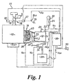
- this shows an engine 10 with a starter and an associated starter circuit 10a which is coupled through a friction clutch 14 with a multi-ratio transmission 12 via a transmission input shaft 15.
- fuel is supplied to the engine by a throttle 16 which includes a throttle valve 18 operated by an accelerator pedal 19.
- the invention is equally applicable to electronic or mechanical fuel injected petrol or diesel engines.
- the clutch 14 is actuated by a release fork 20 which is operated by a slave cylinder 22.
- the transmission is controlled by a ratio selector member in the form of a lever 24 which is connected with the transmission via a selector linkage 25 and which includes a load-sensing switch means 33 which detects forces applied to the lever 24 by the driver and produces a signal Vs indicating an intention to change the operative ratio of the transmission.
- An electronic control unit 36 controls the actuation of the clutch 14 via an hydraulic control 38 which controls the operation of slave cylinder 22.
- Control unit 36 receives signals Vs from selector lever 24 and signals Ve proportional to engine speed from engine speed sensor 26. Signals Vt from throttle valve position sensor 30 proportional to the current throttle opening and accelerator pedal position signals Va from an accelerator position sensor 19a are also fed to control unit 36.
- Control unit 36 also receives a ratio signal Vg from ratio position sensor 32 which corresponds to the transmission ratio currently engaged, signals Vc from slave cylinder position sensor 34, which varying with the position of the slave cylinder, and signals Vdp proportional to clutch driven plate speed from speed sensor 42 which actually senses the speed of the transmission input shaft 15 (which is equal to that of a driven plate 40 of the clutch 14).
- the driven plate speed sensor 42 acts in effect as a vehicle speed sensor and vice versa. Thus in some applications no drive plate speed sensor 42 is provided and this speed is calculated from the transmission ratio and the vehicle speed which is given by a separate sensor.
- a throttle control 37 is operated by the control unit 36 so that the throttle can be opened and closed independently of the accelerator pedal 19.
- a buzzer 50 is connected with control unit 36 to warn/indicate to the vehicle operator when certain vehicle operating conditions occur. In addition to or in place of buzzer 50 a flashing warning light (not shown) may be used.
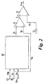
- Control unit 36 includes a reference signal generator 60 (see figure 2) which generates a reference signal Vr representative of a desired engine speed, This reference signal is compared in comparator A with the actual engine speed signal Ve from sensor 26 to produce an error signal E which is compared in comparator B with the clutch actuator position signal Vc from sensor 34 to provide a clutch engagement control signal Vce which control unit 36 outputs to hydraulic control 38. Operation of a control unit in this manner is described in more detail, for example, in the earlier European Patents 0038113 and 0043660 to which the reader should refer if further details are required.
- Co-pending UK Patent Application GB-A-2292591 includes a detailed description of the main reference signal generator 60 which detailed description is hereby incorporated in the present description.
- control unit 36 In addition to controlling the engagement and disengagement of clutch 14 the control unit 36 also controls the throttle setting via control 37 when its control logic indicates that an override of the throttle opening set by the driver's operation of the accelerator 19 is desirable. In some applications the throttle control 37 may be omitted.
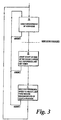
- the electronic control unit 36 includes a routine for determining the kiss-point of clutch 14 which is diagramatically illustrated in figure 3.
- the method is based on the realisation that, with the engine in the throttle closed overrun condition, the torque required to turn over a petrol engine remains relatively constant over a relatively wide range of engine speeds.
- Figure 5 shows a typical engine torque map where, for example, line X indicates that the negative torque remains substantially constant over a relatively wide speed range of say 2000 rpm to 6000 rpm. This negative torque is around 20% of the maximum torque developed by the engine. [It is believed that similar characteristics also apply to diesel engines].
- the clutch is engaged to a level of slippage sufficient for the vehicle to increase the speed of the engine to a substantially constant level the negative torque transmitted by the clutch also remains relatively constant at the above referred to engine turn-over level. If a measurement of the position of the clutch actuating mechanism is made when this negative torque is being transmitted it is then possible knowing the clutch engagement/torque characteristic to compute the kiss-point of the clutch from this measured position.
- FIG. 4 shows typical clutch engagement/torque characteristics where, clutch slip torque is plotted against clutch release bearing position.
- Curves T1, T2 and T3 show the characteristics of the same clutch at different times in its operating life and are therefore of the same curve form.
- Curve T1 shows the characteristic of a new unworn clutch
- T2 shows the characteristic of a half worn clutch
- T3 shows the characteristic of a fully worn clutch.
- Line Y in Figure 4 the so-called coast line, represents the steady state negative turn-over torque which is transmitted by the clutch during a kiss-point determination and is the line along which the clutch position measurements are taken during each kiss-point determination giving clutch release bearing position values (so-called coast points) B, E and G on curves T1, T3 and T2 respectively.
- Points D, F and H define the clutch release bearing positions at which the kiss-point occurs on curves T1, T3 and T2 respectively.
- the kiss-point determination method described below is implemented on 4th to 3rd downshifts in a five speed box as this is a shift where the torque reversed is less evident to the operator and passengers than shifts between lower gears and shifts from 4th to 3rd are more numerous than 5th to 4th shifts.
- the routine for kiss-point calibration is carried out during down changes from 4th to 3rd.
- the electronic control unit 36 checks that the throttle remains closed during the calibration routine and that the engine has been running for sufficient time since start-up for it and the clutch to have reached its normal operating temperature.
- the electronic control unit also estimates on a continual basis [using, for example, the mathematical model that the energy input into the pressure plate is equal to the integral of the product of clutch slip speed and clutch slip torque and also using standard conduction and convection heat transfer theory] the surface temperature of the clutch plate and only performs the calibration when the clutch surface temperature is within specified limits. If any of these conditions is exceeded, or if clutch slip speed does not remain above a lower limit, the calibration is aborted.
- the clutch is disengaged by the control unit 36 and the old gear is disengaged.
- the new gear is then engaged (see Block A) and engine speed and driven plate speeds are measured and a reference speed is set typically halfway between these measured speeds.
- Engagement of the clutch is then commenced by cylinder 22 until engagement just begins (see Block B) from where engagement continues under the control of unit 36 to raise the engine speed, for example, exponentially to the reference speed and then to hold the engine speed constant at the reference speed.
- clutch engagement is completed by raising the reference speed so that the engine speed is raised to the driven plate speed exponentially.
- Time limits are imposed on the periods during which the clutch is slipping to prevent prolonged clutch slippage.
- the amount by which (or rate at which) the kiss-point can change at each determination or the rate at which the kiss-point can be changed is preferably limited to eliminate transient effects. This can be achieved by filtering the individual kiss-point measurements and may be applied as a rate limit to the change.
- kiss-point determination method of the present invention has been described above as being performed during a downshift in the associated transmission it could be implemented in any circumstance in which the engine is operating in an overrun condition.
- the electronic control immediately prior to the electronic control means being de-activated at the end of a vehicle journey the electronic control stores a value of kiss-point position for use at the start of the next vehicle journey.
- This stored figure is related to the final actual kiss-point position computed prior to de-activation of the electronic control means and typically is the average of all the kiss-point positions computed during that journey.
- a 3-dimensional map of clamp load in relation to the release travel and wear could be stored as a sequence of data points. Measurement of the coast point as the wear progresses would enable the clamp load curve for a particular state of wear to be derived from the map and the corresponding kiss-point to be determined by interpolation.
Landscapes
- Engineering & Computer Science (AREA)
- Mechanical Engineering (AREA)
- Transportation (AREA)
- Chemical & Material Sciences (AREA)
- Combustion & Propulsion (AREA)
- Automation & Control Theory (AREA)
- Physics & Mathematics (AREA)
- Fluid Mechanics (AREA)
- General Engineering & Computer Science (AREA)
- Hydraulic Clutches, Magnetic Clutches, Fluid Clutches, And Fluid Joints (AREA)
Abstract
Description
- This invention relates to clutch calibration and in particular to the determination of the so-called "Kiss-point" of a clutch when the clutch just begins to make frictional contact during its engagement.
- It is known to provide clutch control systems in which the clutch is engaged and disengaged by an hydraulic actuator (or some other actuator such as an electric motor) under the control of an electronic control means which, for example, engages the clutch for vehicle start-up when the accelerator is depressed, disengages the clutch when the vehicle comes to a halt, and which disengages the clutch during ratio changes in an associated transmission when a gear selector lever is moved by the operator. Examples of such clutch control systems are disclosed in, for example, European patents 0038113, 0043660, 0059035, 0101220 and 0566595.
- In order to ensure the continued accurate operation of such clutch control systems it is necessary for the electronic control means to know accurately the position of the clutch kiss-point. This therefore presents a problem since the kiss-point changes as the clutch and the associated actuating mechanism wears.
- The closest prior art according to EP-A-385 629 discloses the Kiss-point determination at start-up from rest, but not during the shift mode.
- It is an object of the present invention to provide a method of determining the kiss-point of a clutch which can be regularly implemented during use of the associated vehicle with the minimal effect on the operation of the vehicle so that the determination is not perceived by the operator or passengers.
- Thus according to the present invention there is provided a method of determining, during a clutch re-engagement process, the kiss-point of a vehicle clutch having a driven plate which drives a vehicle from an engine via a multi-ratio transmission, operation of the clutch being via a clutch actuating mechanism under the control of an electronic control means, said method comprising the steps of:-
- checking that the throttle of the engine is closed and that the vehicle is in an engine overrun condition;
- partially re-engaging the clutch up to a point where the clutch increases the engine speed to a substantially constant level below the speed of the driven plate of the clutch;
- measuring the position of the clutch actuating mechanism when in said partially engaged condition;
- computing from said position measurement and the known engagement/torque characteristics of the clutch the current kiss-point position;
- saving said current kiss-point position, and
- completing the engagement of the clutch.
-
- The present invention also provides a method of determining the kiss-point of a vehicle clutch which drives a vehicle from an engine via a multi-ratio transmission, operation of the clutch being via a clutch actuating mechanism under the control of an electronic control means, said method comprising the steps of:-
- determining when a downshift in the operative ratio of the associated transmission has been selected;
- checking that the throttle of the engine is closed;
- disengaging the clutch;
- disengaging the old transmission ratio and engaging the required new ratio;
- partially re-engaging the clutch up to a point where the clutch increases the engine speed to a substantially constant level below the speed of the driven plate of the clutch;
- measuring the position of the clutch actuating mechanism when in said partially engaged condition;
- computing from said position measurement and the known engagement/torque characteristics of the clutch the current kiss-point position;
- saving said current kiss-point position, and
- completing the engagement of the clutch.
-
- In a preferred arrangement the electronic control means senses the engine speed and the speed of the driven plate of the clutch prior to re-engagement and then re-engages the clutch to drive the engine at a speed in a predetermined relationship to said sensed speeds.
- The vehicle engine may conveniently be driven by the clutch at a speed halfway between the sensed engine and driven plate speeds.
- During a given kiss-point determination a series of clutch actuating mechanism position measurements may be made and this series of measurements may be compared for consistency and if sufficiently consistent, indicating a steady state clutch engagement condition, are utilised for a kiss-point determination.
- The electronic control means may set a time limit for making the position measurements of the clutch actuating mechanism to prevent prolonged clutch slippage.
- One embodiment of the present invention will now be described, by way of example only, with reference to the accompanying drawings in which:-
- Figure 1 shows in diagrammatic form the general layout of a clutch control system embodying the present invention;
- Figure 2 shows in block diagram form the generation of the clutch take-up reference signal in the electronic control unit of the present invention;
- Figure 3 shows the logic diagram for the kiss-point determination method of the present invention;
- Figure 4 shows a typical clutch engagement torque characteristic and illustrates its use in the computation of clutch kiss-point, and
- Figure 5 shows a typical engine torque map illustrating the substantially constant negative torque required to turn-over the engine on overrun.
-
- Referring to figure 1 this shows an
engine 10 with a starter and an associatedstarter circuit 10a which is coupled through afriction clutch 14 with amulti-ratio transmission 12 via atransmission input shaft 15. In the example described, fuel is supplied to the engine by athrottle 16 which includes athrottle valve 18 operated by anaccelerator pedal 19. The invention is equally applicable to electronic or mechanical fuel injected petrol or diesel engines. - The
clutch 14 is actuated by arelease fork 20 which is operated by aslave cylinder 22. The transmission is controlled by a ratio selector member in the form of alever 24 which is connected with the transmission via aselector linkage 25 and which includes a load-sensing switch means 33 which detects forces applied to thelever 24 by the driver and produces a signal Vs indicating an intention to change the operative ratio of the transmission. - An
electronic control unit 36 controls the actuation of theclutch 14 via anhydraulic control 38 which controls the operation ofslave cylinder 22.Control unit 36 receives signals Vs fromselector lever 24 and signals Ve proportional to engine speed fromengine speed sensor 26. Signals Vt from throttlevalve position sensor 30 proportional to the current throttle opening and accelerator pedal position signals Va from anaccelerator position sensor 19a are also fed to controlunit 36.Control unit 36 also receives a ratio signal Vg from ratio position sensor 32 which corresponds to the transmission ratio currently engaged, signals Vc from slavecylinder position sensor 34, which varying with the position of the slave cylinder, and signals Vdp proportional to clutch driven plate speed fromspeed sensor 42 which actually senses the speed of the transmission input shaft 15 (which is equal to that of a drivenplate 40 of the clutch 14). Since the speed of the vehicle depends on the driven plate speed and the ratio engaged, the drivenplate speed sensor 42 acts in effect as a vehicle speed sensor and vice versa. Thus in some applications no driveplate speed sensor 42 is provided and this speed is calculated from the transmission ratio and the vehicle speed which is given by a separate sensor. - A
throttle control 37 is operated by thecontrol unit 36 so that the throttle can be opened and closed independently of theaccelerator pedal 19. Abuzzer 50 is connected withcontrol unit 36 to warn/indicate to the vehicle operator when certain vehicle operating conditions occur. In addition to or in place of buzzer 50 a flashing warning light (not shown) may be used. -
Control unit 36 includes a reference signal generator 60 (see figure 2) which generates a reference signal Vr representative of a desired engine speed, This reference signal is compared in comparator A with the actual engine speed signal Ve fromsensor 26 to produce an error signal E which is compared in comparator B with the clutch actuator position signal Vc fromsensor 34 to provide a clutch engagement control signal Vce which controlunit 36 outputs tohydraulic control 38. Operation of a control unit in this manner is described in more detail, for example, in the earlier European Patents 0038113 and 0043660 to which the reader should refer if further details are required. Co-pending UK Patent Application GB-A-2292591 includes a detailed description of the mainreference signal generator 60 which detailed description is hereby incorporated in the present description. - In addition to controlling the engagement and disengagement of
clutch 14 thecontrol unit 36 also controls the throttle setting viacontrol 37 when its control logic indicates that an override of the throttle opening set by the driver's operation of theaccelerator 19 is desirable. In some applications thethrottle control 37 may be omitted. - In accordance with the present invention the
electronic control unit 36 includes a routine for determining the kiss-point ofclutch 14 which is diagramatically illustrated in figure 3. - The method is based on the realisation that, with the engine in the throttle closed overrun condition, the torque required to turn over a petrol engine remains relatively constant over a relatively wide range of engine speeds. This is illustrated in Figure 5 which shows a typical engine torque map where, for example, line X indicates that the negative torque remains substantially constant over a relatively wide speed range of say 2000 rpm to 6000 rpm. This negative torque is around 20% of the maximum torque developed by the engine. [It is believed that similar characteristics also apply to diesel engines]. Thus if the clutch is engaged to a level of slippage sufficient for the vehicle to increase the speed of the engine to a substantially constant level the negative torque transmitted by the clutch also remains relatively constant at the above referred to engine turn-over level. If a measurement of the position of the clutch actuating mechanism is made when this negative torque is being transmitted it is then possible knowing the clutch engagement/torque characteristic to compute the kiss-point of the clutch from this measured position.
- The above is illustrated in Figure 4 which shows typical clutch engagement/torque characteristics where, clutch slip torque is plotted against clutch release bearing position. Curves T1, T2 and T3 show the characteristics of the same clutch at different times in its operating life and are therefore of the same curve form. Curve T1 shows the characteristic of a new unworn clutch, T2 shows the characteristic of a half worn clutch and T3 shows the characteristic of a fully worn clutch.
- Line Y in Figure 4, the so-called coast line, represents the steady state negative turn-over torque which is transmitted by the clutch during a kiss-point determination and is the line along which the clutch position measurements are taken during each kiss-point determination giving clutch release bearing position values (so-called coast points) B, E and G on curves T1, T3 and T2 respectively. Points D, F and H define the clutch release bearing positions at which the kiss-point occurs on curves T1, T3 and T2 respectively. The ratio AB/CD = AE/CF =AG/CH in Figure 3 so that knowing the positions B, E and G and the shape of the Curves T1, T3 and T2 respectively the corresponding kiss-points D, F and H can be computed.
- It will be noted in the clutch characteristic shown that the difference AB - CD (marked p), AE - CF (marked q), and AG - CH (marked r) increases up to an approximately half worn clutch condition and then decreases. Such wear characteristics need to be taken into account to give a more accurate kiss-point determination.
- If during a given kiss-point determination the clutch position measurement gives a value of say S in Figure 4 the corresponding kiss-point T is derived from the ratio AB/CD = AS/CT.
- The kiss-point determination method described below is implemented on 4th to 3rd downshifts in a five speed box as this is a shift where the torque reversed is less evident to the operator and passengers than shifts between lower gears and shifts from 4th to 3rd are more numerous than 5th to 4th shifts.
- Referring to Figure 3, the routine for kiss-point calibration is carried out during down changes from 4th to 3rd. The
electronic control unit 36 checks that the throttle remains closed during the calibration routine and that the engine has been running for sufficient time since start-up for it and the clutch to have reached its normal operating temperature. The electronic control unit also estimates on a continual basis [using, for example, the mathematical model that the energy input into the pressure plate is equal to the integral of the product of clutch slip speed and clutch slip torque and also using standard conduction and convection heat transfer theory] the surface temperature of the clutch plate and only performs the calibration when the clutch surface temperature is within specified limits. If any of these conditions is exceeded, or if clutch slip speed does not remain above a lower limit, the calibration is aborted. - At the start of the 4th to 3rd shift the clutch is disengaged by the
control unit 36 and the old gear is disengaged. The new gear is then engaged (see Block A) and engine speed and driven plate speeds are measured and a reference speed is set typically halfway between these measured speeds. - Engagement of the clutch is then commenced by
cylinder 22 until engagement just begins (see Block B) from where engagement continues under the control ofunit 36 to raise the engine speed, for example, exponentially to the reference speed and then to hold the engine speed constant at the reference speed. - Once the engine has attained the selected reference speed (see Block C) a series of measurements of the engagement position of the clutch are made within a time limit and provided that this series of measurements is sufficiently consistent [indicating that the engine speed is also substantially constant and that the engine is receiving the substantially constant negative turn-over torque via the clutch] these measurements are used for subsequent computation of the clutch kiss-point position from the known clutch engagement/torque characteristic as outlined above. Typically the system looks to receive three consecutive substantially equal measurements before saving the position measurement for subsequent kiss-point computation.
- On expiry of the measurement time limit, or on completion of the requisite number of consistent clutch engagement position measurements, clutch engagement is completed by raising the reference speed so that the engine speed is raised to the driven plate speed exponentially.
- Time limits are imposed on the periods during which the clutch is slipping to prevent prolonged clutch slippage.
- During a given journey the amount by which (or rate at which) the kiss-point can change at each determination or the rate at which the kiss-point can be changed is preferably limited to eliminate transient effects. This can be achieved by filtering the individual kiss-point measurements and may be applied as a rate limit to the change.
- Although the kiss-point determination method of the present invention has been described above as being performed during a downshift in the associated transmission it could be implemented in any circumstance in which the engine is operating in an overrun condition.
- Also, immediately prior to the electronic control means being de-activated at the end of a vehicle journey the electronic control stores a value of kiss-point position for use at the start of the next vehicle journey. This stored figure is related to the final actual kiss-point position computed prior to de-activation of the electronic control means and typically is the average of all the kiss-point positions computed during that journey.
- Although the invention has been described above in relation to a transmission in which the operative ratio is selected manually using
lever 24 it is equally applicable to a transmission in which the operative ratio is selected automatically bycontrol unit 36 or to a transmission which can operate both manually or automatically at the choice of the vehicle operator. - Also, although the above described ratio technique [i.e. AC/CD = AE/CF = AG/CH] is used for the computation of the kiss-point from the measured steady state negative turn-over torque condition other relationships could be used for different clutch engagement/torque characteristics.
- For example, a 3-dimensional map of clamp load in relation to the release travel and wear could be stored as a sequence of data points. Measurement of the coast point as the wear progresses would enable the clamp load curve for a particular state of wear to be derived from the map and the corresponding kiss-point to be determined by interpolation.
Claims (12)
- A method of determining, during a clutch re-engagement process, the kiss-point of a vehicle clutch (14) having a driven plate (40) which drives a vehicle from an engine (10) via a multi-ratio transmission (12), operation of the clutch (14) being via a clutch actuating mechanism (20, 22) under the control of an electronic control means (36), characterised in that the method comprises the steps of:-checking that the throttle (18) of the engine (10) is closed and that the vehicle is in an engine overrun condition;partially re-engaging the clutch (14) up to a point where the clutch increases the engine speed to a substantially constant level below the speed of the driven plate (40) of the clutch (14);measuring the position of the clutch actuating mechanism (20, 22) when in said partially engaged condition;computing from said position measurement and the known engagement/torque characteristics of the clutch (14) the current kiss-point position;saving said current kiss-point position; andcompleting the engagement of the clutch (14).
- A method of determining the kiss-point of a vehicle clutch (14) having a driven plate (40) which drives a vehicle from an engine (10) via a multi-ratio transmission (12), operation of the clutch (14) being via a clutch actuating mechanism (20, 22) under the control of an electronic control means (36), characterised in that said method comprises the steps of:-determining when a downshift in the operative ratio of the associated transmission (12) has been selected;checking that the throttle (18) is closed;disengaging the clutch (14);disengaging the old transmission ratio and engaging the required new ratio;partially re-engaging the clutch (10) up to a point where the clutch (10) increases the engine speed to a substantially constant level below the speed of the driven plate (40) of the clutch (14);measuring the position of the clutch actuating mechanism (20, 22) when in said partially engaged condition;computing from said position measurement and the known engagement/torque characteristics of the clutch (14) the current kiss-point position;saving said current kiss-point position; andcompleting the engagement of the clutch (14).
- A method according to claim 1 or 2 characterised in that the electronic control means (36) senses the engine speed and the speed of the driven plate (40) of the clutch (14) prior to re-engagement and then re-engages the clutch (14) to drive the engine (10) at a speed in a predetermined relationship to said sensed speeds.
- A method according to claims 1 to 3 characterised in that the engine (10) is driven at a speed halfway between the sensed engine and driven plate speeds.
- A method according to any one of claims 1 to 4 characterised in that during a given kiss-point determination a series of clutch actuating mechanism position measurements are made and said series of measurements are compared for consistency and if sufficiently consistent, indicating a steady state clutch engagement condition, are utilised for a kiss-point determination.
- A method according to claim 5 characterised in that a time limit is set by the electronic control means (36) for making the position measurements of the clutch actuating mechanism (20, 22) to prevent prolonged clutch slippage.
- A method according to any one of claims 1 to 6 characterised in that a given kiss-point determination is aborted if the throttle (18) does not remain closed or if the driven plate speed does not remain above a lower limit or if the temperature of the clutch (14), or an estimate of the temperature of the clutch (14), exceeds a predetermined level.
- A method according to any one of claims 1 to 7 characterised in that a preliminary step of checking that the engine (10) has been operating for a sufficient time to ensure that normal clutch operating temperature has been reached, is included.
- A method according to any one of claims 1 to 8 characterised in that the amount by which the measured kiss-point position can be changed at each determination or the rate at which the kiss-point can be changed is restricted to limit transient effects.
- A method according to any one of claims 1 to 9 characterised in that immediately prior to each de-activation of the electronic control means (36) at the end of each vehicle journey the control means (36) stores a value of kiss-point position related to the final actual kiss-point position computed during that specific journey.
- A method according to claim 10 characterised in that the value of kiss-point position stored at the end of each vehicle journey is equal to the average of all the kiss-point positions computed during that specific journey.
- A clutch control system which includes an electronic control means characterised in that the electronic control means performs a routine for determining the kiss-point of the associated clutch in accordance with the method of any one of claims 1 to 11.
Applications Claiming Priority (3)
| Application Number | Priority Date | Filing Date | Title |
|---|---|---|---|
| GB9626527 | 1996-12-20 | ||
| GBGB9626527.7A GB9626527D0 (en) | 1996-12-20 | 1996-12-20 | Clutches |
| PCT/GB1997/003497 WO1998028162A1 (en) | 1996-12-20 | 1997-12-19 | Clutch control system |
Publications (2)
| Publication Number | Publication Date |
|---|---|
| EP0883509A1 EP0883509A1 (en) | 1998-12-16 |
| EP0883509B1 true EP0883509B1 (en) | 2002-03-20 |
Family
ID=10804778
Family Applications (1)
| Application Number | Title | Priority Date | Filing Date |
|---|---|---|---|
| EP97950287A Expired - Lifetime EP0883509B1 (en) | 1996-12-20 | 1997-12-19 | Clutch control system |
Country Status (8)
| Country | Link |
|---|---|
| US (1) | US6086514A (en) |
| EP (1) | EP0883509B1 (en) |
| JP (1) | JP2001501289A (en) |
| KR (1) | KR100572261B1 (en) |
| AU (1) | AU5329898A (en) |
| DE (1) | DE69711170T2 (en) |
| GB (2) | GB9626527D0 (en) |
| WO (1) | WO1998028162A1 (en) |
Cited By (1)
| Publication number | Priority date | Publication date | Assignee | Title |
|---|---|---|---|---|
| DE102005021711A1 (en) * | 2005-05-11 | 2007-02-08 | Zf Friedrichshafen Ag | Method for determining the application point of an automatically actuated friction clutch |
Families Citing this family (41)
| Publication number | Priority date | Publication date | Assignee | Title |
|---|---|---|---|---|
| JP3598847B2 (en) * | 1998-10-28 | 2004-12-08 | いすゞ自動車株式会社 | Clutch connection / disconnection device |
| DE10012122A1 (en) * | 1999-03-15 | 2000-09-21 | Luk Lamellen & Kupplungsbau | Clutch control system for operating a motor vehicle clutch automatically utilizes an uncoupling fork and a slave cylinder triggered by an electronic control device regulating clutch operations with a hydraulic control. |
| DE19951527C1 (en) * | 1999-10-26 | 2001-06-13 | Siemens Ag | Control for an automatically actuated clutch of a motor vehicle and method for controlling an automatically actuated clutch |
| FR2819564B1 (en) | 2001-01-17 | 2003-03-14 | Renault | METHOD FOR ESTABLISHING THE CLUTCH CURVE OF A CLUTCH MEMBER MOUNTED BETWEEN AN INTERNAL COMBUSTION ENGINE AND A GEARBOX OF A MOTOR VEHICLE PROPLUSED BY THIS ENGINE |
| WO2002084136A1 (en) * | 2001-04-11 | 2002-10-24 | Luk Lamellen Und Kupplungsbau Beteiligungs Kg | Method and device for determining the point of contact of a clutch |
| US6494810B1 (en) | 2001-05-30 | 2002-12-17 | Eaton Corporation | Clutch calibration and control |
| FR2828450B1 (en) | 2001-08-07 | 2003-10-03 | Renault | STARTING ASSISTANCE DEVICE FOR A MOTOR VEHICLE |
| JP3712193B2 (en) * | 2001-12-10 | 2005-11-02 | 本田技研工業株式会社 | Engagement control method of friction engagement element in power transmission device |
| FR2833667B1 (en) * | 2001-12-17 | 2004-04-09 | Renault | SYSTEM FOR DIAGNOSING THE CLUTCH WEAR OF A MOTOR VEHICLE |
| JP4542307B2 (en) * | 2002-10-18 | 2010-09-15 | アイシン精機株式会社 | Clutch control device |
| DE502004001568D1 (en) * | 2003-06-23 | 2006-11-09 | Luk Lamellen & Kupplungsbau | Method and device for controlling a clutch |
| DE102004007160A1 (en) * | 2004-02-12 | 2005-08-25 | Volkswagen Ag | Process to achieve smooth automotive acceleration while changing gear by regulation of clutch speed within a defined range |
| US7912613B2 (en) * | 2004-07-01 | 2011-03-22 | Yamaha Hatsudoki Kabushiki Kaisha | Riding type vehicle |
| CN100451372C (en) * | 2006-01-05 | 2009-01-14 | 财团法人工业技术研究院 | Method for defining clutch contact point and torsion characteristic curve |
| DE602006018702D1 (en) | 2006-03-30 | 2011-01-20 | Ind Tech Res Inst | Method to define a coupling point and a related torque characteristic |
| DE102007002343A1 (en) * | 2007-01-16 | 2008-07-17 | Zf Friedrichshafen Ag | Method for dynamically determining a clutch resting point |
| ATE460322T1 (en) * | 2007-07-05 | 2010-03-15 | Magneti Marelli Spa | METHOD FOR CONTROLLING A VEHICLE EQUIPPED WITH A MECHANICAL SERVO TRANSMISSION |
| DE102007057081B4 (en) * | 2007-11-21 | 2009-12-24 | Bayerische Motoren Werke Aktiengesellschaft | Method for setting a point of engagement of a friction clutch |
| DE102008000770A1 (en) * | 2008-03-19 | 2009-09-24 | Robert Bosch Gmbh | Method and device for closing a clutch |
| US8577570B2 (en) * | 2009-04-17 | 2013-11-05 | Honda Motor Co., Ltd. | Touch point calibration method for a motor vehicle |
| DE102010024941A1 (en) * | 2009-07-16 | 2011-01-20 | Luk Lamellen Und Kupplungsbau Beteiligungs Kg | Kupplungstastpunkte |
| FR2950303B1 (en) | 2009-09-24 | 2011-10-28 | Peugeot Citroen Automobiles Sa | METHOD OF LEARNING THE LATCHING POINT OF A CLUTCH BY THE CHARACTERISTIC CURVE OF THE CLUTCH FOR A HYBRID VEHICLE |
| DE102009053885B4 (en) * | 2009-11-20 | 2015-10-29 | Getrag Getriebe- Und Zahnradfabrik Hermann Hagenmeyer Gmbh & Cie Kg | Method for kisspoint adaptation |
| DE102010039172B4 (en) * | 2010-08-11 | 2023-12-07 | Zf Friedrichshafen Ag | Method for determining an application actuation pressure value of a frictional switching element |
| EP2458249B1 (en) | 2010-11-25 | 2017-01-04 | Transmisiones y Equipos Mecánicos, S.A. de C.V. | Method of controlling a double clutch in a vehicle transmission, and clutch control system for controlling a double clutch |
| SE535679C2 (en) * | 2011-03-14 | 2012-11-06 | Scania Cv Ab | Method and system for determining a contact point for a connection |
| JP2014035069A (en) * | 2012-08-10 | 2014-02-24 | Yamaha Motor Co Ltd | Vehicle |
| CN104755782B (en) * | 2012-10-31 | 2017-04-12 | 舍弗勒技术股份两合公司 | Method for actuating a friction clutch |
| KR101406625B1 (en) | 2012-11-09 | 2014-06-11 | 기아자동차주식회사 | Touch point searching method for clutch |
| KR101355620B1 (en) * | 2012-11-09 | 2014-01-27 | 기아자동차주식회사 | Touch point searching method for clutch |
| US9127729B2 (en) | 2013-08-16 | 2015-09-08 | GM Global Technology Operations LLC | Method of learning a clutch kiss point for a clutch of a dual clutch transmission |
| KR101470209B1 (en) * | 2013-09-17 | 2014-12-05 | 현대자동차주식회사 | Method and apparatus for controlling clutch in hybrid vehicle |
| EP3221609B1 (en) * | 2014-11-19 | 2021-07-07 | Dana Automotive Systems Group, LLC | A method to control clutch force in a clutch pack |
| US10240643B2 (en) * | 2014-12-11 | 2019-03-26 | PT Tech, LLC | Self-contained clutch for diesel engines |
| KR101755851B1 (en) | 2015-10-01 | 2017-07-10 | 현대자동차주식회사 | Method for learning touch point of clutch for vehicles |
| KR101916545B1 (en) | 2016-12-15 | 2018-11-07 | 현대자동차주식회사 | Touch point learning apparatus and method for clutch |
| KR102461506B1 (en) * | 2017-09-25 | 2022-11-02 | 현대자동차주식회사 | Method for controlling clutch of vehicles with automated manual transmission |
| CN111433478B (en) * | 2017-12-13 | 2021-10-19 | Gkn汽车有限公司 | Method for operating a clutch device |
| DE102020104153A1 (en) | 2020-02-18 | 2021-08-19 | Bayerische Motoren Werke Aktiengesellschaft | Method for tracking an operating point of a clutch and a motor vehicle with a clutch |
| CN114215861B (en) * | 2021-12-13 | 2023-09-22 | 义乌吉利自动变速器有限公司 | Intelligent clutch adjusting method, device, equipment and storage medium |
| US11685258B1 (en) * | 2022-06-27 | 2023-06-27 | Ford Global Technologies, Llc | System and method to reduce transfer clutch overheating |
Family Cites Families (23)
| Publication number | Priority date | Publication date | Assignee | Title |
|---|---|---|---|---|
| AU548876B2 (en) * | 1980-02-18 | 1986-01-09 | Automotive Products Ltd. | Standing-start clutch control |
| DE3174453D1 (en) * | 1980-07-08 | 1986-05-28 | Automotive Prod Plc | Clutch control system |
| AU552105B2 (en) * | 1981-02-24 | 1986-05-22 | Automotive Products Ltd. | Clutch control system |
| AU1725283A (en) * | 1982-08-11 | 1984-02-16 | Automotive Products Plc | Clutch control system |
| US4646891A (en) * | 1985-01-31 | 1987-03-03 | Eaton Corporation | Automatic clutch control |
| JPH06104427B2 (en) * | 1985-07-05 | 1994-12-21 | 富士通株式会社 | Inching control method for vehicles with automatic transmission |
| US4711141A (en) * | 1986-04-30 | 1987-12-08 | Eaton Corporation | Method for controlling AMT system including after transmission gear change clutch and fuel control |
| JP2636283B2 (en) * | 1987-12-11 | 1997-07-30 | いすゞ自動車株式会社 | Automatic clutch control |
| US4899858A (en) * | 1989-03-02 | 1990-02-13 | Eaton Corporation | Method and control system for updating of control parameter value indicative of master clutch point of incipient engagement |
| US5184301A (en) * | 1990-11-27 | 1993-02-02 | Navistar International Transportation Corp. | Automotive vehicle microprocessor control having clutch priority engine speed control |
| GB9101164D0 (en) * | 1991-01-18 | 1991-02-27 | Automotive Prod Plc | Clutch control system |
| DE4134669C2 (en) * | 1991-10-19 | 1998-07-02 | Mannesmann Sachs Ag | Arrangement for detecting the position of starting torque transmission of a motor vehicle clutch |
| US5337868A (en) * | 1992-01-02 | 1994-08-16 | Eaton Corporation | Touch point identification for automatic clutch controller |
| US5332074A (en) * | 1992-01-06 | 1994-07-26 | Eaton Corporation | Incipient clutch control system |
| US5314050A (en) * | 1992-12-09 | 1994-05-24 | Eaton Corporation | Clutch mode control logic |
| US5337874A (en) * | 1993-03-19 | 1994-08-16 | Eaton Corporation | Method/system for determining clutch touch point |
| US5383823A (en) * | 1993-06-10 | 1995-01-24 | Eaton Corporation | Clutch control |
| US5411124A (en) * | 1993-08-26 | 1995-05-02 | Eaton Corporation | Method and apparatus for determining clutch touch point |
| GB9402730D0 (en) * | 1994-02-12 | 1994-04-06 | Automotive Products Plc | Clutch control system |
| US5439428A (en) * | 1994-02-22 | 1995-08-08 | Eaton Corporation | Method and apparatus for robust automatic clutch control with pid regulation |
| US5634867A (en) * | 1994-09-19 | 1997-06-03 | Eaton Corporation | Main clutch reengagement control for a double clutch downshift |
| GB9504681D0 (en) * | 1995-03-08 | 1995-04-26 | Eaton Corp | Improvements in vehicle control |
| NO314174B1 (en) * | 1995-12-18 | 2003-02-10 | Luk Getriebe Systeme Gmbh | Motor vehicles |
-
1996
- 1996-12-20 GB GBGB9626527.7A patent/GB9626527D0/en active Pending
-
1997
- 1997-12-19 AU AU53298/98A patent/AU5329898A/en not_active Abandoned
- 1997-12-19 US US09/117,855 patent/US6086514A/en not_active Expired - Fee Related
- 1997-12-19 GB GB9816927A patent/GB2324584B/en not_active Revoked
- 1997-12-19 DE DE69711170T patent/DE69711170T2/en not_active Expired - Lifetime
- 1997-12-19 WO PCT/GB1997/003497 patent/WO1998028162A1/en active IP Right Grant
- 1997-12-19 EP EP97950287A patent/EP0883509B1/en not_active Expired - Lifetime
- 1997-12-19 JP JP10528534A patent/JP2001501289A/en active Pending
-
1998
- 1998-08-19 KR KR10-1998-0706448A patent/KR100572261B1/en not_active IP Right Cessation
Cited By (1)
| Publication number | Priority date | Publication date | Assignee | Title |
|---|---|---|---|---|
| DE102005021711A1 (en) * | 2005-05-11 | 2007-02-08 | Zf Friedrichshafen Ag | Method for determining the application point of an automatically actuated friction clutch |
Also Published As
| Publication number | Publication date |
|---|---|
| GB2324584B (en) | 2000-09-06 |
| GB2324584A (en) | 1998-10-28 |
| US6086514A (en) | 2000-07-11 |
| AU5329898A (en) | 1998-07-17 |
| JP2001501289A (en) | 2001-01-30 |
| WO1998028162A1 (en) | 1998-07-02 |
| KR19990087062A (en) | 1999-12-15 |
| DE69711170T2 (en) | 2002-11-14 |
| EP0883509A1 (en) | 1998-12-16 |
| GB9626527D0 (en) | 1997-02-05 |
| DE69711170D1 (en) | 2002-04-25 |
| KR100572261B1 (en) | 2007-03-02 |
| GB9816927D0 (en) | 1998-09-30 |
Similar Documents
| Publication | Publication Date | Title |
|---|---|---|
| EP0883509B1 (en) | Clutch control system | |
| EP0616142B1 (en) | Method/system for determining clutch touch point | |
| AU672307B2 (en) | Touch point identification algorithm for automatic clutch controller | |
| US4873637A (en) | Control for vehicle start from stop operation | |
| US6482123B2 (en) | Method of controlling heat buildup in a clutch | |
| EP0385629B1 (en) | Method and system for updating of control parameter value indicative of master clutch point of incipient engagement | |
| EP0328299B1 (en) | Control for automatic mechanical transmission system start from stop operation | |
| US4646891A (en) | Automatic clutch control | |
| US6602161B2 (en) | Arrangement for operating the clutch in the power train of a motor vehicle | |
| AU663036B2 (en) | Clutch mode control logic | |
| EP0696341B1 (en) | Clutch control system | |
| KR100376593B1 (en) | Clutch control system | |
| JP2873348B2 (en) | Control device for automatic clutch type transmission | |
| AU689681B2 (en) | Integrated engine and transmission control system | |
| GB2097074A (en) | Transmission control system in a vehicle | |
| JPH1071875A (en) | Automobile and method to be applied to this automobile | |
| EP0244131B1 (en) | Method for controlling amt system including after transmission gear change clutch and fuel control | |
| US6440039B1 (en) | Torque-transmitting system | |
| EP1201955B1 (en) | Method of updating the transmissibility function of a clutch during a gear change | |
| JPH0620842B2 (en) | Vehicle start control device |
Legal Events
| Date | Code | Title | Description |
|---|---|---|---|
| PUAI | Public reference made under article 153(3) epc to a published international application that has entered the european phase |
Free format text: ORIGINAL CODE: 0009012 |
|
| AK | Designated contracting states |
Kind code of ref document: A1 Designated state(s): DE ES FR GB IT |
|
| 17P | Request for examination filed |
Effective date: 19981216 |
|
| RAP1 | Party data changed (applicant data changed or rights of an application transferred) |
Owner name: LUK LEAMINGTON LIMITED |
|
| 17Q | First examination report despatched |
Effective date: 20000724 |
|
| GRAG | Despatch of communication of intention to grant |
Free format text: ORIGINAL CODE: EPIDOS AGRA |
|
| GRAG | Despatch of communication of intention to grant |
Free format text: ORIGINAL CODE: EPIDOS AGRA |
|
| GRAG | Despatch of communication of intention to grant |
Free format text: ORIGINAL CODE: EPIDOS AGRA |
|
| GRAH | Despatch of communication of intention to grant a patent |
Free format text: ORIGINAL CODE: EPIDOS IGRA |
|
| GRAH | Despatch of communication of intention to grant a patent |
Free format text: ORIGINAL CODE: EPIDOS IGRA |
|
| REG | Reference to a national code |
Ref country code: GB Ref legal event code: IF02 |
|
| GRAA | (expected) grant |
Free format text: ORIGINAL CODE: 0009210 |
|
| AK | Designated contracting states |
Kind code of ref document: B1 Designated state(s): DE ES FR GB IT |
|
| REF | Corresponds to: |
Ref document number: 69711170 Country of ref document: DE Date of ref document: 20020425 |
|
| ET | Fr: translation filed | ||
| PG25 | Lapsed in a contracting state [announced via postgrant information from national office to epo] |
Ref country code: ES Free format text: LAPSE BECAUSE OF FAILURE TO SUBMIT A TRANSLATION OF THE DESCRIPTION OR TO PAY THE FEE WITHIN THE PRESCRIBED TIME-LIMIT Effective date: 20020925 |
|
| PLBE | No opposition filed within time limit |
Free format text: ORIGINAL CODE: 0009261 |
|
| STAA | Information on the status of an ep patent application or granted ep patent |
Free format text: STATUS: NO OPPOSITION FILED WITHIN TIME LIMIT |
|
| 26N | No opposition filed |
Effective date: 20021223 |
|
| PGFP | Annual fee paid to national office [announced via postgrant information from national office to epo] |
Ref country code: IT Payment date: 20071220 Year of fee payment: 11 |
|
| PGFP | Annual fee paid to national office [announced via postgrant information from national office to epo] |
Ref country code: GB Payment date: 20081217 Year of fee payment: 12 |
|
| PGFP | Annual fee paid to national office [announced via postgrant information from national office to epo] |
Ref country code: FR Payment date: 20100106 Year of fee payment: 13 |
|
| PGFP | Annual fee paid to national office [announced via postgrant information from national office to epo] |
Ref country code: DE Payment date: 20091229 Year of fee payment: 13 |
|
| GBPC | Gb: european patent ceased through non-payment of renewal fee |
Effective date: 20091219 |
|
| PG25 | Lapsed in a contracting state [announced via postgrant information from national office to epo] |
Ref country code: GB Free format text: LAPSE BECAUSE OF NON-PAYMENT OF DUE FEES Effective date: 20091219 |
|
| REG | Reference to a national code |
Ref country code: FR Ref legal event code: ST Effective date: 20110831 |
|
| PG25 | Lapsed in a contracting state [announced via postgrant information from national office to epo] |
Ref country code: FR Free format text: LAPSE BECAUSE OF NON-PAYMENT OF DUE FEES Effective date: 20110103 |
|
| REG | Reference to a national code |
Ref country code: DE Ref legal event code: R119 Ref document number: 69711170 Country of ref document: DE Effective date: 20110701 |
|
| PG25 | Lapsed in a contracting state [announced via postgrant information from national office to epo] |
Ref country code: DE Free format text: LAPSE BECAUSE OF NON-PAYMENT OF DUE FEES Effective date: 20110701 |
|
| PG25 | Lapsed in a contracting state [announced via postgrant information from national office to epo] |
Ref country code: IT Free format text: LAPSE BECAUSE OF NON-PAYMENT OF DUE FEES Effective date: 20081219 |