EP0883260A2 - Error correction in a digital transmission system - Google Patents
Error correction in a digital transmission system Download PDFInfo
- Publication number
- EP0883260A2 EP0883260A2 EP98304125A EP98304125A EP0883260A2 EP 0883260 A2 EP0883260 A2 EP 0883260A2 EP 98304125 A EP98304125 A EP 98304125A EP 98304125 A EP98304125 A EP 98304125A EP 0883260 A2 EP0883260 A2 EP 0883260A2
- Authority
- EP
- European Patent Office
- Prior art keywords
- error
- word
- error correction
- data
- zero
- Prior art date
- Legal status (The legal status is an assumption and is not a legal conclusion. Google has not performed a legal analysis and makes no representation as to the accuracy of the status listed.)
- Withdrawn
Links
Images


Classifications
-
- H—ELECTRICITY
- H04—ELECTRIC COMMUNICATION TECHNIQUE
- H04L—TRANSMISSION OF DIGITAL INFORMATION, e.g. TELEGRAPHIC COMMUNICATION
- H04L1/00—Arrangements for detecting or preventing errors in the information received
- H04L1/004—Arrangements for detecting or preventing errors in the information received by using forward error control
- H04L1/0056—Systems characterized by the type of code used
- H04L1/0057—Block codes
-
- H—ELECTRICITY
- H04—ELECTRIC COMMUNICATION TECHNIQUE
- H04L—TRANSMISSION OF DIGITAL INFORMATION, e.g. TELEGRAPHIC COMMUNICATION
- H04L25/00—Baseband systems
- H04L25/02—Details ; arrangements for supplying electrical power along data transmission lines
- H04L25/03—Shaping networks in transmitter or receiver, e.g. adaptive shaping networks
- H04L25/03828—Arrangements for spectral shaping; Arrangements for providing signals with specified spectral properties
- H04L25/03866—Arrangements for spectral shaping; Arrangements for providing signals with specified spectral properties using scrambling
-
- H—ELECTRICITY
- H04—ELECTRIC COMMUNICATION TECHNIQUE
- H04L—TRANSMISSION OF DIGITAL INFORMATION, e.g. TELEGRAPHIC COMMUNICATION
- H04L12/00—Data switching networks
- H04L12/54—Store-and-forward switching systems
- H04L12/56—Packet switching systems
- H04L12/5601—Transfer mode dependent, e.g. ATM
- H04L2012/5672—Multiplexing, e.g. coding, scrambling
- H04L2012/5673—Coding or scrambling
Definitions
- This invention relates to a method and apparatus for correction of random bit errors in a digital transmission system.
- error correction is becoming increasingly important in ATM (asynchronous transfer mode) and other digital transmission systems where traffic from a number of different users is multiplexed together into ATM cells or into virtual containers which are routed over a common connection.
- a particular problem with these systems is that of error multiplication where payloads have been scrambled and subsequently descrambled. This can lead to duplication of errors within a cell, or, depending on the position of the error in a cell, the introduction of a duplicated error in the next cell.
- Present systems do not differentiate between these duplicated errors and isolated errors and this can lead to miscorrection of some errors and thus to the introduction of new errors.
- An object of the invention is to minimise or to overcome this disadvantage.
- a further object of the invention is to provide an improved apparatus and method for detection and correction of single bit or symbol errors and multiple errors in a digital transmission system.
- a method of detecting and correcting random symbol errors in a digital transmission system comprising determining whether an error is an isolated symbol error or a multiple error, and performing separate correction of isolated and multiple errors.
- a method of detecting and correcting random bit errors in a digital transmission system in which data is scrambled and subsequently descrambled including parsing the descrambled data into words, determining a syndrome error word for each said data word, determining a parity error word for each said data word, leaving a said data word uncorrected when its corresponding syndrome error and parity error words are both zero, performing single bit error correction of a said data word when its corresponding syndrome error and parity error words are both non-zero, and performing double bit error correction of a said word when its corresponding parity error word is zero and its corresponding syndrome error word is non-zero.
- an arrangement for detecting and correcting random bit errors in a digital transmission system in which data is scrambled and subsequently descrambled including means for parsing the descrambled data into words, means for determining a syndrome error word for each said data word, means for determining a parity error word for each said data word and for leaving a said data word uncorrected when its corresponding syndrome error and parity error words are both zero, first correction means for performing single bit error correction of a said data word when its corresponding syndrome error and parity error words are both non-zero, and second correction means for performing double bit error correction of a said word when its corresponding parity error word is zero and its corresponding syndrome error word is non-zero.
- a digital transmission system comprising a transmitter incorporating means for scrambling data, a receiver incorporating means for descrambling the scrambled data received over a transmission channel from the transmitter and having means for detecting and correcting bit errors in the descrambled data, means for parsing the descrambled data into words, means for determining a syndrome error word for each said data word, means for determining a parity error word for each said data word and for leaving a said data word uncorrected when its corresponding syndrome error and parity error words are both zero, first correction means for performing single bit error correction of a said data word when its corresponding syndrome error and parity error words are both non-zero, and second correction means for performing double bit error correction of a said word when its corresponding parity error word is zero and its corresponding syndrome error word is non-zero.
- the symbols may represent corresponding elements of a Galois field and may compprise a cyclic or other linear code.
- the technique makes use of a class of cyclic redundancy checksums (CRC) with the ability to perform simultaneous correction and detection to discriminate between isolated bit errors and error multiplication effects caused by physical layer scramblers and line-codes.
- CRC cyclic redundancy checksums
- An example of this technique is the use of a class of code words for single bit correction and double bit detection which takes the form of an (x+1).f(x) polynomial where f(x) is a primitive or irreducible polynomial.
- This operation is extended to perform single bit error correction and double bit error correction to take account of double bit error multiplication effects introduced by many scramblers and line-codes.
- code words of greater Hamming distance the method can be extended to perform correction to take account of error multiplication of greater than 2 times.
- a CRC-10 cyclic redundancy code is used to provide error protection over part or all of the payloads of ATM cells.
- the invention enables random bit errors introduced in the channel to be detected and corrected irrespective of the error multiplication introduced by a scrambler, e.g. an x 43 +1 scrambler.
- the use of a scrambler is well recognised when transporting ATM cells over synchronous frame structures in the SDH (synchronous digital hierarchy) and PDH (plesiochronous digital hierarchy).
- One application of the technique is the use of the CRC-10 cyclic redundancy code to protect payload data within the newly emerging, composite user adaptation layer (AAL-CU) although any other CRC of similar properties may be applied in this manner.
- AAL-CU composite user adaptation layer
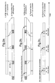
- FIG. 1a The implementation of a x 43 +1 scrambler and de-scrambler employed in a digital transmission system is shown in figures 1a and 1b respectively.
- the operation of the scrambling and de-scrambling process is well known to those skilled in the art.
- the scrambler circuit (figure 1a) performs a summation of the current bit sample i(x) with a running sum of previous samples occurring at integer multiples of 43 bit offsets from the current sample to produce the scrambled output t(x).
- the de-scrambler (figure 1b) operates on the received signal r(x) to reverse the scrambling process by subtracting the current data sample from the previous data sample offset by 43 bit positions.
- FIG. 2a illustrates this.
- the payloads of the ATM cells are fed in a continuous manner into the scrambler.
- the ATM cell headers are appended to the payloads and transmitted across the communications channel.
- the process is reversed as shown in figure 2b.
- the headers are removed and the payloads fed into the de-scrambler. In the absence of errors the output is identical to the input. However if bit errors are introduced by the channel then the de-scrambling process will multiply them, each single bit error resulting in 2 bit errors in the descrambled payload as shown in figure 2c.
- the duplicated errors are offset from each other by 43 bits. Additionally, as the payloads are applied continuously to the scrambler a single bit error in one payload may spill over into the following payload due to this multiplication effect. Thus if the original bit in error occurs in payload bit positions 0 to 341 then the second bit error will occur in the same ATM payload which will then contain a double bit error. If however the original bit error occurs in payload bit position 342 to 383 then the secondary error will spill into the following payload and two consecutive ATM payloads will then each contain a single bit error.
- the preferred CRC-10 code described below comprises a 9th degree primitive polynomial code multiplied by (x+1) This code may be used to perform single bit correction and multiple bit detection over up to 511 bits. As the standard ATM payload is just 384 bits, the code is shortened. It will thus be appreciated that there will be unused syndromes even if the full payload is protected by the CRC. It is important to note that although the scrambling process is continuous the generation and decoding of the CRC is a blocked operation which occurs over a single (or part) of a payload only. The CRC operation is not dependent on previously occurring ATM samples. The generation of the CRC is performed prior to the scrambling process and the detection/correction performed after the de-scrambling process.
- the CRC-10 polynomial:- x 10 + x 9 + x 4 + x + 1 can be factorised into the form:- both factors being irreducible or primitive polynomials.
- the CRC-10 code employed can simultaneously correct those 86 single bit error positions, and those 341 double bit positions.
- the decoding of the received code-word post de-scrambling is performed by the decoder/error correction arrangement shown in schematic form in figure 3.
- the decoder/error correction arrangement of figure 3 comprises four main blocks: a buffer register 131 that is used for temporary storage of the received code-word whilst the initial syndrome is computed; a CRC syndrome register 132 that computes the error syndrome from the received word; an x+1 parity register 133 that checks the parity of the received word; and an error correction stage that detects the bit positions of the bits in error and corrects them.
- the error correction stage includes of two circuits. One circuit 134a is used to detect and correct single bit errors, the other circuit 134b detects and corrects double bit errors.
- a selection circuit 135 selects on or other of the outputs of the error correction circuits 134a, 134b according to whether a single bit error or a double bit error has been corrected.
- the received word is shifted simultaneously into the buffer register 131, the syndrome register 132 and the parity register 133.
- the syndrome register is used to compute a syndrome error word, a non zero value indicating that an error has been detected in the received word.
- the parity register computes a parity check on the received word. If a value of ONE is computed, this indicates that the parity register has detected an odd number of errors in the received word. If a value of ZERO is computed, this indicates that either no bit errors or an even number of bit errors have been computed in the received word.
- the computed syndrome and the computed parity are decoded to determine the status of the received word.
- a zero syndrome and zero parity indicates that no error has been detected in the received word.
- the received word is then assumed error free and no further corrective action is required.
- the parity is zero (an odd number of errored bits is not detected by the parity check) and the syndrome is non-zero (an error detected by the syndrome decoder) then it is assumed that a double bit error has occurred, and further that the errored bits are offset by 43 bit positions due to the scrambler. Corrective action can be taken to correct the two bits in error and thus the double bit correction circuitry is selected.
- the syndrome is read into the selected error detection circuit.
- the error detection circuit is a simple combinatorial logic circuit designed such that its output is high if the error syndrome corresponds to an error pattern with an error in the highest order bit position for the single bit error scenario (or with an error in both the highest order bit position and the bit position offset by the error multiplication distance for the double bit error scenario.
- the errored bit position is assumed to be in the highest order bit position (and offset) of the received word.
- the cyclic nature of the syndrome is used to find the errored bit position.
- the syndrome is shifted cyclically one bit position and a new comparison made. If a match is found then this new bit position indicates the location of the error(s).
- the syndrome is therefore shifted cyclically one bit at a time until a match is found. Simultaneously the received word is shifted from the buffer register. When a match is found, indicating the errored bit positions, the bits in error may be corrected and the syndrome reset. No further corrective action is required and the remaining bits of the received word are clocked out of the buffer register.
- Additional protection against mis-correction of multiple bit errors may be performed by further analysis of the computed syndrome, and a comparison of the errored bit position indicated by the process together with the knowledge of the error multiplication effects introduced by the system.
Abstract
Description
Claims (19)
- A method of detecting and correcting random symbol errors in a digital transmission system, the method comprising determining whether an error is an isolated symbol error or a multiple error, and performing separate correction of said isolated and multiple errors.
- A method as claimed in claim 1, wherein said symbols correspond to elements of a Galois field.
- A method as claimed in claim 2, wherein said symbols represent a cyclic code.
- A method as claimed in claim 3, wherein said multiple errors are double or duplicated errors.
- A method of detecting and correcting random bit errors in a digital transmission system in which data is scrambled and subsequently descrambled, the method including parsing the descrambled data into words, determining a syndrome error word for each said data word, determining a parity error word for each said data word, leaving a said data word uncorrected when its corresponding syndrome error and parity error words are both zero, performing single bit error correction of a said data word when its corresponding syndrome error and parity error words are both non-zero, and performing double bit error correction of a said word when its corresponding parity error word is zero and its corresponding syndrome error word is non-zero.
- A method as claimed in claim 5, wherein said scrambled data is carried as a payload in an asynchronous transfer mode (ATM) cell stream.
- A method as claimed in claim 6, wherein said single bit error correction is performed via a first error correction code, and wherein said double bit error correction is performed via a second error correction code.
- A method as claimed in claim 7, wherein said first error correction code comprises a ninth degree primitive or irreducible polynomial.
- A method as claimed in claim 8, wherein said second error correction code comprises the product of said first error correction code polynomial and a first degree polynomial.
- A method as claimed in claim 5, wherein miscorrection of multiple bit errors is inhibited by comparison of the error positions with the descrambler characteristics.
- An arrangement for detecting and correcting random bit errors in a digital transmission system in which data is scrambled and subsequently descrambled, the arrangement including means for parsing the descrambled data into words, means for determining a syndrome error word for each said data word, means for determining a parity error word for each said data word and for leaving a said data word uncorrected when its corresponding syndrome error and parity error words are both zero, first correction means for performing single bit error correction of a said data word when its corresponding syndrome error and parity error words are both non-zero, and second correction means for performing double bit error correction of a said word when its corresponding parity error word is zero and its corresponding syndrome error word is non-zero.
- An arrangement as claimed in claim 11, wherein said first error correction means provides error correction via a first error correction code, and wherein said second error correction means provides error correction via a second error correction code.
- An arrangement as claimed in claim 12, wherein said first error correction code comprises a ninth degree primitive or irreducible polynomial.
- An arrangement as claimed in claim 13, wherein said second error correction code comprises the product of said first error correction code polynomial and a first degree polynomial.
- A digital transmission system comprising a transmitter incorporating means for scrambling data, a receiver incorporating means for descrambling the scrambled data received over a transmission channel from the transmitter and having means for detecting and correcting bit errors in the descrambled data, means for parsing the descrambled data into words, means for determining a syndrome error word for each said data word, means for determining a parity error word for each said data word and for leaving a said data word uncorrected when its corresponding syndrome error and parity error words are both zero, first correction means for performing single bit error correction of a said data word when its corresponding syndrome error and parity error words are both non-zero, and second correction means for performing double bit error correction of a said word when its corresponding parity error word is zero and its corresponding syndrome error word is non-zero.
- A digital transmission system as claimed in claim 15, wherein said scrambler is an x43+1 scrambler.
- A digital transmission system as claimed in claim 16, wherein said first error correction means provides error correction via a first error correction code, and wherein said second error correction means provides error correction via a second error correction code.
- A digital transmission system as claimed in claim 17, wherein said first error correction code comprises a ninth degree primitive or irreducible polynomial.
- A digital transmission system as claimed in claim 18, wherein said second error correction code comprises the product of said first error correction code polynomial and a first degree polynomial.
Applications Claiming Priority (2)
| Application Number | Priority Date | Filing Date | Title |
|---|---|---|---|
| US869352 | 1997-06-05 | ||
| US08/869,352 US5923680A (en) | 1997-06-05 | 1997-06-05 | Error correction in a digital transmission system |
Publications (2)
| Publication Number | Publication Date |
|---|---|
| EP0883260A2 true EP0883260A2 (en) | 1998-12-09 |
| EP0883260A3 EP0883260A3 (en) | 2005-02-02 |
Family
ID=25353396
Family Applications (1)
| Application Number | Title | Priority Date | Filing Date |
|---|---|---|---|
| EP98304125A Withdrawn EP0883260A3 (en) | 1997-06-05 | 1998-05-26 | Error correction in a digital transmission system |
Country Status (4)
| Country | Link |
|---|---|
| US (1) | US5923680A (en) |
| EP (1) | EP0883260A3 (en) |
| CA (1) | CA2235178A1 (en) |
| GB (1) | GB2326067A (en) |
Cited By (5)
| Publication number | Priority date | Publication date | Assignee | Title |
|---|---|---|---|---|
| US6826595B1 (en) | 2000-07-05 | 2004-11-30 | Sap Portals Israel, Ltd. | Internet collaboration system and method |
| WO2008052858A3 (en) * | 2006-11-03 | 2008-06-19 | Ibm | Forward error correction encoding for multiple link transmission compatible with 64b/66b scrambling |
| WO2010000623A2 (en) * | 2008-07-01 | 2010-01-07 | International Business Machines Corporation | Cyclical redundancy code for use in a high-speed serial link |
| US8139430B2 (en) | 2008-07-01 | 2012-03-20 | International Business Machines Corporation | Power-on initialization and test for a cascade interconnect memory system |
| US8516338B2 (en) | 2008-07-01 | 2013-08-20 | International Business Machines Corporation | Error correcting code protected quasi-static bit communication on a high-speed bus |
Families Citing this family (14)
| Publication number | Priority date | Publication date | Assignee | Title |
|---|---|---|---|---|
| JPH1141114A (en) * | 1997-07-18 | 1999-02-12 | Sony Corp | Transmitting device and receiving device and communication method and radio communication system |
| US6609226B1 (en) * | 2000-04-10 | 2003-08-19 | Nortel Networks Limited | Networking device and method for making cyclic redundancy check (CRC) immune to scrambler error duplication |
| US7473715B2 (en) * | 2001-05-02 | 2009-01-06 | Zephyros, Inc. | Two component (epoxy/amine) structural foam-in-place material |
| US7284184B2 (en) * | 2003-01-30 | 2007-10-16 | International Business Machines Corporation | Forward error correction scheme compatible with the bit error spreading of a scrambler |
| US7765454B2 (en) * | 2005-05-24 | 2010-07-27 | Sgi International, Inc. | Fault tolerant memory system |
| US7694204B2 (en) * | 2006-03-09 | 2010-04-06 | Silicon Image, Inc. | Error detection in physical interfaces for point-to-point communications between integrated circuits |
| US7913151B1 (en) * | 2006-05-26 | 2011-03-22 | Pmc-Sierra, Inc. | Forward error correction with self-synchronous scramblers |
| CN102035616B (en) * | 2009-09-30 | 2013-12-04 | 国际商业机器公司 | Frame boundary detection and synchronization system for data streams received by forward error correction (FEC) layer of Ethernet |
| US8381083B2 (en) * | 2009-10-22 | 2013-02-19 | Arm Limited | Error control coding for single error correction and double error detection |
| FR2983665B1 (en) * | 2011-12-02 | 2014-06-20 | Commissariat Energie Atomique | METHOD FOR GENERATING A MAXIMIZED LINEAR CORRECTING CODE, METHOD AND DEVICE FOR DECODING A CODE |
| US9218239B2 (en) * | 2013-06-13 | 2015-12-22 | Micron Technology, Inc. | Apparatuses and methods for error correction |
| MX2020003509A (en) | 2017-10-03 | 2020-07-22 | Ericsson Telefon Ab L M | Interleaving before crc coding a nr pbch payload including known bits to enhance polar code performance. |
| JP2020135391A (en) * | 2019-02-19 | 2020-08-31 | キオクシア株式会社 | Memory system |
| US11095307B2 (en) * | 2019-09-03 | 2021-08-17 | Nvidia Corporation | Performing cyclic redundancy checks using parallel computing architectures |
Citations (4)
| Publication number | Priority date | Publication date | Assignee | Title |
|---|---|---|---|---|
| US3771126A (en) * | 1972-04-10 | 1973-11-06 | Bell Telephone Labor Inc | Error correction for self-synchronized scramblers |
| US3775746A (en) * | 1972-05-19 | 1973-11-27 | Ibm | Method and apparatus for detecting odd numbers of errors and burst errors of less than a predetermined length in scrambled digital sequences |
| GB2131253A (en) * | 1982-11-24 | 1984-06-13 | Motorola Ltd | Error-correcting decoder |
| US5179560A (en) * | 1989-05-15 | 1993-01-12 | Mitsubishi Denki Kabushiki Kaisha | Apparatus for decoding bch code for correcting complex error |
Family Cites Families (4)
| Publication number | Priority date | Publication date | Assignee | Title |
|---|---|---|---|---|
| US4435807A (en) * | 1980-06-26 | 1984-03-06 | Scott Edward W | Orchard error correction system |
| US4592054A (en) * | 1982-10-22 | 1986-05-27 | Mitsubishi Denki Kabushiki Kaisha | Decoder with code error correcting function |
| US5195098A (en) * | 1991-05-10 | 1993-03-16 | Echelon Corporation | Binary data error correction using hint signal |
| WO1995028046A1 (en) * | 1994-04-08 | 1995-10-19 | Echelon Corporation | Method and apparatus for robust communications based upon angular modulation |
-
1997
- 1997-06-05 US US08/869,352 patent/US5923680A/en not_active Expired - Lifetime
-
1998
- 1998-02-27 GB GB9804105A patent/GB2326067A/en not_active Withdrawn
- 1998-05-26 EP EP98304125A patent/EP0883260A3/en not_active Withdrawn
- 1998-06-04 CA CA002235178A patent/CA2235178A1/en not_active Abandoned
Patent Citations (4)
| Publication number | Priority date | Publication date | Assignee | Title |
|---|---|---|---|---|
| US3771126A (en) * | 1972-04-10 | 1973-11-06 | Bell Telephone Labor Inc | Error correction for self-synchronized scramblers |
| US3775746A (en) * | 1972-05-19 | 1973-11-27 | Ibm | Method and apparatus for detecting odd numbers of errors and burst errors of less than a predetermined length in scrambled digital sequences |
| GB2131253A (en) * | 1982-11-24 | 1984-06-13 | Motorola Ltd | Error-correcting decoder |
| US5179560A (en) * | 1989-05-15 | 1993-01-12 | Mitsubishi Denki Kabushiki Kaisha | Apparatus for decoding bch code for correcting complex error |
Non-Patent Citations (1)
| Title |
|---|
| LAU R ET AL: "Forward error correction for BISDN: implementation and analysis" COUNTDOWN TO THE NEW MILENNIUM. PHOENIX, DEC. 2 - 5, 1991, PROCEEDINGS OF THE GLOBAL TELECOMMUNICATIONS CONFERENCE. (GLOBECOM), NEW YORK, IEEE, US, vol. VOL. 3, 2 December 1991 (1991-12-02), pages 1638-1643, XP010042601 ISBN: 0-87942-697-7 * |
Cited By (9)
| Publication number | Priority date | Publication date | Assignee | Title |
|---|---|---|---|---|
| US6826595B1 (en) | 2000-07-05 | 2004-11-30 | Sap Portals Israel, Ltd. | Internet collaboration system and method |
| WO2008052858A3 (en) * | 2006-11-03 | 2008-06-19 | Ibm | Forward error correction encoding for multiple link transmission compatible with 64b/66b scrambling |
| JP2010508742A (en) * | 2006-11-03 | 2010-03-18 | インターナショナル・ビジネス・マシーンズ・コーポレーション | Forward error correction coding for multilink transmission compatible with 64B / 66B scrambling |
| CN101529775B (en) * | 2006-11-03 | 2013-04-17 | 国际商业机器公司 | Forward error correction encoding for multiple link transmission compatible with 64b/66b scrambling |
| WO2010000623A2 (en) * | 2008-07-01 | 2010-01-07 | International Business Machines Corporation | Cyclical redundancy code for use in a high-speed serial link |
| WO2010000623A3 (en) * | 2008-07-01 | 2010-02-25 | International Business Machines Corporation | Cyclical redundancy code for use in a high-speed serial link |
| US8139430B2 (en) | 2008-07-01 | 2012-03-20 | International Business Machines Corporation | Power-on initialization and test for a cascade interconnect memory system |
| US8201069B2 (en) | 2008-07-01 | 2012-06-12 | International Business Machines Corporation | Cyclical redundancy code for use in a high-speed serial link |
| US8516338B2 (en) | 2008-07-01 | 2013-08-20 | International Business Machines Corporation | Error correcting code protected quasi-static bit communication on a high-speed bus |
Also Published As
| Publication number | Publication date |
|---|---|
| EP0883260A3 (en) | 2005-02-02 |
| GB2326067A (en) | 1998-12-09 |
| GB9804105D0 (en) | 1998-04-22 |
| US5923680A (en) | 1999-07-13 |
| CA2235178A1 (en) | 1998-12-05 |
Similar Documents
| Publication | Publication Date | Title |
|---|---|---|
| US5923680A (en) | Error correction in a digital transmission system | |
| US8055984B2 (en) | Forward error correction scheme compatible with the bit error spreading of a scrambler | |
| US4979174A (en) | Error correction and detection apparatus and method | |
| US7426679B2 (en) | Cyclic redundancy check circuit for use with self-synchronous scramblers | |
| KR100376822B1 (en) | Apparatus and method for synchronization and error detection of packetized data streams | |
| US7996747B2 (en) | Forward error correction encoding for multiple link transmission compatible with 64B/66B scrambling | |
| US5461629A (en) | Error correction in a spread spectrum transceiver | |
| US8136013B2 (en) | Burst error correction based on fire code | |
| US8020077B1 (en) | Forward error correction with self-synchronous scramblers | |
| US20050028066A1 (en) | Error correction on M-bit encoded links | |
| US20080082896A1 (en) | Burst error correction with offset for correction vector based on fire code | |
| EP1217748A2 (en) | In-band FEC decoder for SONET | |
| US20030051200A1 (en) | Method and apparatus for detecting start position of code sequence, and decoding method and apparatus using the same | |
| US20020104053A1 (en) | In-band FEC encoder for sonet | |
| Tong | Correction of synchronization errors with burst-error-correcting cyclic codes | |
| US7313748B2 (en) | FEC decoder and method | |
| EP1217750A2 (en) | Optimized parallel in parallel out GF(2M) squarer for FEC decoder | |
| Juan | Erroneous MPEG packet synchronization in the MCNS/SCTE/ITU-T J. 83 Annex B standard | |
| JP2952051B2 (en) | Cell synchronous operation circuit in ATM | |
| US20020046370A1 (en) | Error checking | |
| Gorshe | Concurrent error detection | |
| EP1217751A2 (en) | Optimized parallel in parallel out GF(2M) multiplier for FEC decoder | |
| EP1217749A2 (en) | In-band FEC error performance monitoring module for SONET | |
| JP2873533B2 (en) | ATMHEC synchronization circuit | |
| EP1204232A1 (en) | Detection of uncorrectable data blocks in coded communications systems |
Legal Events
| Date | Code | Title | Description |
|---|---|---|---|
| PUAI | Public reference made under article 153(3) epc to a published international application that has entered the european phase |
Free format text: ORIGINAL CODE: 0009012 |
|
| AK | Designated contracting states |
Kind code of ref document: A2 Designated state(s): AT BE CH CY DE DK ES FI FR GB GR IE IT LI LU MC NL PT SE |
|
| AX | Request for extension of the european patent |
Free format text: AL;LT;LV;MK;RO;SI |
|
| RAP3 | Party data changed (applicant data changed or rights of an application transferred) |
Owner name: NORTEL NETWORKS CORPORATION |
|
| RAP1 | Party data changed (applicant data changed or rights of an application transferred) |
Owner name: NORTEL NETWORKS LIMITED |
|
| RAP1 | Party data changed (applicant data changed or rights of an application transferred) |
Owner name: NORTEL NETWORKS LIMITED |
|
| PUAL | Search report despatched |
Free format text: ORIGINAL CODE: 0009013 |
|
| AK | Designated contracting states |
Kind code of ref document: A3 Designated state(s): AT BE CH CY DE DK ES FI FR GB GR IE IT LI LU MC NL PT SE |
|
| AX | Request for extension of the european patent |
Extension state: AL LT LV MK RO SI |
|
| 17P | Request for examination filed |
Effective date: 20050802 |
|
| AKX | Designation fees paid |
Designated state(s): DE FR GB |
|
| 17Q | First examination report despatched |
Effective date: 20051128 |
|
| STAA | Information on the status of an ep patent application or granted ep patent |
Free format text: STATUS: THE APPLICATION IS DEEMED TO BE WITHDRAWN |
|
| 18D | Application deemed to be withdrawn |
Effective date: 20070908 |