EP0882679A1 - Process and melting furnace for vitrifying heavy metal containing waste - Google Patents
Process and melting furnace for vitrifying heavy metal containing waste Download PDFInfo
- Publication number
- EP0882679A1 EP0882679A1 EP98810463A EP98810463A EP0882679A1 EP 0882679 A1 EP0882679 A1 EP 0882679A1 EP 98810463 A EP98810463 A EP 98810463A EP 98810463 A EP98810463 A EP 98810463A EP 0882679 A1 EP0882679 A1 EP 0882679A1
- Authority
- EP
- European Patent Office
- Prior art keywords
- furnace
- melt
- fraction
- discharge
- main
- Prior art date
- Legal status (The legal status is an assumption and is not a legal conclusion. Google has not performed a legal analysis and makes no representation as to the accuracy of the status listed.)
- Withdrawn
Links
Images
Classifications
-
- C—CHEMISTRY; METALLURGY
- C03—GLASS; MINERAL OR SLAG WOOL
- C03B—MANUFACTURE, SHAPING, OR SUPPLEMENTARY PROCESSES
- C03B5/00—Melting in furnaces; Furnaces so far as specially adapted for glass manufacture
- C03B5/16—Special features of the melting process; Auxiliary means specially adapted for glass-melting furnaces
- C03B5/235—Heating the glass
-
- C—CHEMISTRY; METALLURGY
- C03—GLASS; MINERAL OR SLAG WOOL
- C03B—MANUFACTURE, SHAPING, OR SUPPLEMENTARY PROCESSES
- C03B3/00—Charging the melting furnaces
-
- C—CHEMISTRY; METALLURGY
- C03—GLASS; MINERAL OR SLAG WOOL
- C03B—MANUFACTURE, SHAPING, OR SUPPLEMENTARY PROCESSES
- C03B5/00—Melting in furnaces; Furnaces so far as specially adapted for glass manufacture
- C03B5/005—Melting in furnaces; Furnaces so far as specially adapted for glass manufacture of glass-forming waste materials
-
- C—CHEMISTRY; METALLURGY
- C03—GLASS; MINERAL OR SLAG WOOL
- C03B—MANUFACTURE, SHAPING, OR SUPPLEMENTARY PROCESSES
- C03B5/00—Melting in furnaces; Furnaces so far as specially adapted for glass manufacture
- C03B5/02—Melting in furnaces; Furnaces so far as specially adapted for glass manufacture in electric furnaces, e.g. by dielectric heating
- C03B5/027—Melting in furnaces; Furnaces so far as specially adapted for glass manufacture in electric furnaces, e.g. by dielectric heating by passing an electric current between electrodes immersed in the glass bath, i.e. by direct resistance heating
- C03B5/03—Tank furnaces
-
- C—CHEMISTRY; METALLURGY
- C03—GLASS; MINERAL OR SLAG WOOL
- C03B—MANUFACTURE, SHAPING, OR SUPPLEMENTARY PROCESSES
- C03B5/00—Melting in furnaces; Furnaces so far as specially adapted for glass manufacture
- C03B5/02—Melting in furnaces; Furnaces so far as specially adapted for glass manufacture in electric furnaces, e.g. by dielectric heating
- C03B5/033—Melting in furnaces; Furnaces so far as specially adapted for glass manufacture in electric furnaces, e.g. by dielectric heating by using resistance heaters above or in the glass bath, i.e. by indirect resistance heating
- C03B5/0332—Tank furnaces
-
- C—CHEMISTRY; METALLURGY
- C03—GLASS; MINERAL OR SLAG WOOL
- C03B—MANUFACTURE, SHAPING, OR SUPPLEMENTARY PROCESSES
- C03B5/00—Melting in furnaces; Furnaces so far as specially adapted for glass manufacture
- C03B5/16—Special features of the melting process; Auxiliary means specially adapted for glass-melting furnaces
- C03B5/26—Outlets, e.g. drains, siphons; Overflows, e.g. for supplying the float tank, tweels
- C03B5/262—Drains, i.e. means to dump glass melt or remove unwanted materials
-
- C—CHEMISTRY; METALLURGY
- C03—GLASS; MINERAL OR SLAG WOOL
- C03B—MANUFACTURE, SHAPING, OR SUPPLEMENTARY PROCESSES
- C03B5/00—Melting in furnaces; Furnaces so far as specially adapted for glass manufacture
- C03B5/16—Special features of the melting process; Auxiliary means specially adapted for glass-melting furnaces
- C03B5/26—Outlets, e.g. drains, siphons; Overflows, e.g. for supplying the float tank, tweels
- C03B5/265—Overflows; Lips; Tweels
-
- Y—GENERAL TAGGING OF NEW TECHNOLOGICAL DEVELOPMENTS; GENERAL TAGGING OF CROSS-SECTIONAL TECHNOLOGIES SPANNING OVER SEVERAL SECTIONS OF THE IPC; TECHNICAL SUBJECTS COVERED BY FORMER USPC CROSS-REFERENCE ART COLLECTIONS [XRACs] AND DIGESTS
- Y02—TECHNOLOGIES OR APPLICATIONS FOR MITIGATION OR ADAPTATION AGAINST CLIMATE CHANGE
- Y02P—CLIMATE CHANGE MITIGATION TECHNOLOGIES IN THE PRODUCTION OR PROCESSING OF GOODS
- Y02P40/00—Technologies relating to the processing of minerals
- Y02P40/50—Glass production, e.g. reusing waste heat during processing or shaping
- Y02P40/57—Improving the yield, e-g- reduction of reject rates
Definitions
- the invention relates to a method for glazing heavy metals Residues with a chlorine content from flue gas cleaning of more than 10 mass%, especially filter dust and residues from flue gas scrubbing, in which the residues are melted in a melting furnace and are then discharged, with the purpose of conditioning the melt Additives can be added, as well as a melting furnace for implementation of the procedure.
- a method of this type is for example from the DE 43 40 754 A1 is known, and a deglor oven is described, for example, in EP 0 633 411 A1 described.
- the Deglor process has been used for the glazing of residues small content of metal chlorides, metal sulfates and metal sulfites as they typically present in the filter dust, well proven.
- the filter ash is mixed with the highly chlorine-containing product of flue gas cleaning.
- the exhaust gases are subjected to lime washing, calcium compounds, in particular CaSO 3 , Ca SO 4 and CaCl 2 , being produced as by-products, which are to be melted and glazed together with the filter ash.
- this product contains 10 to 20% by mass of chlorine, predominantly in the form of CaCl 2 .
- This compound has a boiling point (> 1600 ° C) that is far above the usual operating temperatures. As a result, these chlorides cannot be converted into the vapor phase effectively enough. At the same time, only a small part of chlorine can be incorporated into the glass.
- Another disadvantage is that due to the additional additives required, the additional amount of exhaust gas as well as the larger amount to be evaporated Material of the energy requirement of the Deglor plant increases.
- alkali-containing reagents such as NaHCO 3
- flue gas cleaning instead of lime, alkali-containing reagents, such as NaHCO 3 , are used for flue gas cleaning, as a result of which it is no longer necessary to add alkali-containing additives to the melting furnace in order to increase the evaporation rate of the chlorides.
- the invention tries to avoid all of these disadvantages.
- You have the task based, a method and an apparatus for vitrifying heavy metal Residues with high chlorine content from flue gas cleaning of the above Specify the type in which the amount of required alkali-containing additives is reduced is, and the throughput of residues can be increased.
- the required electrical power and the amount of exhaust gas are reduced so that lower overall operating costs.
- a more economical Heavy metals can be recovered from the condensate.
- this is achieved in that in a method according to the preamble of claim 1, in the main furnace, which cannot be integrated into the melt Components of the residues are separated into two fractions, whereby the first fraction the volatile components and the second fraction the contains salt-like, less volatile components, and the first fraction evaporated, led out of the furnace with the exhaust gas and collected as condensate and the second fraction as liquid salt from the surface of the Melt is separated and discharged.
- the invention is based on the unexpected finding that when the melting plant according to DE 196 03 365.9 is operated, a stable, thin layer of salt can form on the surface of the glass-like melt, which layer consists practically exclusively of CaCl 2 , NaCl and KCl and in particular one compared to that Condensate contains a smaller concentration of heavy metals. According to the invention, the entire salt is no longer evaporated together with the other volatile constituents of the residue.
- this is carried out in a melting furnace for carrying out the method achieved according to the preamble of claim 8 in that in the outer wall the main furnace has a side outlet for that on the glass melt floating salt is provided.
- the lower edge of this side opening is in a height of approx. 1 to 10 cm above that determined by the outlet stone Melting levels arranged.
- the advantages of the invention include that the condensate is heavily enriched with heavy metals that a reprocessing purpose Heavy metal recovery is worthwhile again.
- Compared to the known state of the Technology can also reduce the amount of alkaline additives and the furnace temperature can be reduced, so that on the one hand the life span the furnace parts are extended and on the other hand the required electrical Performance can be reduced. There is a significant increase in Throughput of residual material, so that overall the operating costs of the plant are reduced will.
- a mass ratio between the first Fraction, i.e. the condensate, and the second fraction, i.e. the liquid salt is set, which depends on the composition of the residue is in the range of 0.1 to 10.
- the size of the mass ratio between the first and the second fraction is determined by the choice of process parameters, preferably temperature, amount of exhaust gas and amount of alkali-containing additives, set. It is important that the evaporation of the salt, i.e. the second fraction, is restricted. This happens, for example, by the amount of exhaust gas and / or the temperature above the melt or the amount of alkali-containing additives can be reduced.
- layer thicknesses in the upper Area advantageous if the residues with high production rates in the Melting furnace can be fed.
- the in the main furnace for the purpose of controlling the Exhaust gas volume from the furnace additionally introduced air before entering the main furnace is preheated by the liquid salt flowing from the main oven.
- the amount of flue gas from the furnace is adjusted by the amount of supply air thus the proportion of the evaporated components is also determined.
- the opening for the salt discharge in the melting furnace is arranged near the partition between the main and discharge furnace. This prevents the discharged salt from being unmelted Residue is contaminated.
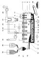
- the single figure shows a schematic representation of the furnace and the front or. downstream units.
- the figure shows schematically a melting furnace 1, which consists of a main furnace 2 a melting tank 3 located in the lower part for receiving the Melt 4 and consists of a discharge furnace 5.
- the discharge furnace 5 is with the The melting tank 3 is connected via a siphon 30 and by means of a partition 6 separated from the main oven 2.
- the discharge furnace 5 is an overflow as a discharge device 7 with a discharge stone 8 arranged to discharge the glass melt 4.
- a first heater in the form of electrical heating elements 9, which of ceramic protective tubes are surrounded, protrudes from above into the gas space 10 of the main furnace 2, without being immersed in the melt 4.
- a second heater in the form of electric heating elements 11 also protrude from above into the discharge furnace 5, without touching the melt 4.
- a removal device 13 for the exhaust gas 14 is also provided.
- an inlet 31 is arranged, which is above the Levels of melt 4 is located.
- the feed is carried out by means of a loading device 15, for example a screw conveyor.
- Such a melting furnace is the subject of EP 0 633 441 A1, to which hereby expressly referred to avoid repetition becomes.
- the opening 16 there is a side opening in the outer wall of the main furnace 2 16 arranged, which is provided for a salt discharge to be described is.
- the underside of the opening 16 is at a height of approximately 1 to 10 cm above the level of the melting level, which when operating the furnace without Salt layer arises. This melting level is approximately at the level of the outlet stone 8.
- the opening 16 can also be used simultaneously for the Dosing of supply air 17 can be used.
- the additives are essentially needed to get out of the residue 18 to produce easily meltable and stable glass. Not with the invention more all chlorine-containing constituents of the residues are evaporated off more , the additives containing alhali according to DE 196 03 365.9 are not more required or can be used in a much smaller dose.
- the proportion of volatile components which are evaporated and collected as condensate, in particular heavy metal chlorides (first fraction 22) and the proportion of salt-like components which are in the form of liquid Salt 23 (second fraction) is separated from the melt 4 and discharged through the opening 16 either continuously or batchwise and collected in a container 24.
- the second fraction 23 contains the less volatile components, in particular CaCl 2 , NaCl and KCl.
- the melt 4 is continuously or intermittently from the discharge furnace 5 withdrawn and deposited or processed as a glass-like product 29.
- the exhaust gases 14 from the melting furnace including the evaporated first fraction 22 are sucked out of the melting furnace by means of a fan 25 and cooled with cold air 26 (quenched). This will condense and desublimate them Heavy metal compounds from the gas and can be downstream Filters, e.g. Bag filter 27, separated as condensate 28 and processed later will.
- the filtered air can, for example, go to the waste incineration plant to be led back.
- the condensate 28 Due to the different evaporation characteristics between the two fractions 22 and 23, the generally more volatile heavy metals, such as Pb, which go into the condensate 28 are separated from the hardly volatile NaCl, KCl and CaCl 2 , which are mainly to be discharged as salt.
- the condensate 28 is now so heavily enriched with heavy metals that it is worth working up again for the purpose of recovering heavy metals.
- the mass ratio of Condensate 28 and liquid salt 23 are between 0.1 and 10.
- the thickness of the salt layer 23 should be larger than 1 cm to ensure a clean separation from the one below Ensure glass melt 4. Layer thicknesses are preferably between To aim for 3 and 10 cm. Larger values are then particularly of Advantage if the residues 18 are fed into the melting furnace 1 at high feed rates will.
- the lateral opening 16 now forms one Overflow for the salt 23 floating on the surface of the melt 4, the can be collected in a laterally attached container 24. To this This enables continuous operation of the system. So that is carried out Salt is not contaminated by unmelted residues 18, it is expedient, the opening 16 for the salt discharge near the partition 6 between to arrange the main furnace 2 and the discharge furnace 5.
- the opening 16 can at the same time for metering supply air 17 into the main furnace be used.
- the amount of exhaust gas 14 is determined by the amount of supply air 17 set out of the oven and thus the proportion of evaporated components co-determined. It is favorable if the hot salt flowing out of the opening 16 23 is used to preheat the supply air 17.
Abstract
Description
Die Erfindung betrifft ein Verfahren zum Verglasen von schwermetallhaltigen Reststoffen mit einem über 10 Massen-% liegenden Chlorgehalt aus der Rauchgasreinigung, insbesondere von Filterstaub und Rückständen aus der Rauchgaswäsche, bei welchem die Reststoffe in einem Schmelzofen eingeschmolzen und anschliessend ausgetragen werden, wobei zwecks Konditionierung der Schmelze Zuschlagstoffe zugegeben werden können, sowie einen Schmelzofen zur Durchführung des Verfahrens. Ein Verfahren dieser Gattung ist beispielsweise aus der DE 43 40 754 A1 bekannt, und ein Deglor-Ofen ist beispielsweise in EP 0 633 411 A1 beschrieben.The invention relates to a method for glazing heavy metals Residues with a chlorine content from flue gas cleaning of more than 10 mass%, especially filter dust and residues from flue gas scrubbing, in which the residues are melted in a melting furnace and are then discharged, with the purpose of conditioning the melt Additives can be added, as well as a melting furnace for implementation of the procedure. A method of this type is for example from the DE 43 40 754 A1 is known, and a deglor oven is described, for example, in EP 0 633 411 A1 described.
Es ist bekannt, mittels Schmelzverfahren schwermetallhaltige Reststoffe, wie Filterasche aus der Kehrrichtverbrennung, zu behandeln. Bei Temperaturen von ca. 1300 bis 1400 °C werden diese Reststoffe i. a. ohne Zuschlagstoffe in einem elektrischen Schmelzofen eingeschmolzen, aus dem Ofen ausgetragen und dann abgekühlt, so dass ein glasartiger Rückstand entsteht, welcher problemlos deponiert werden kann.It is known to use residues containing heavy metals, such as filter ash, by means of melting processes from rubbish incineration. At temperatures of approx. 1300 to 1400 ° C these residues i. a. without additives in one electric melting furnace melted, discharged from the furnace and then cooled, so that a glass-like residue is formed, which is deposited without any problems can be.
Beim Deglor-Verfahren wird durch eine Heizung auch oberhalb der Schmelze dafür gesorgt, dass aufgrund ausreichend hoher Temperaturen im Gasraum ein wesentlicher Anteil der Schwermetalle abgedampft wird. Das mittels eines Ventilators aus dem Ofen abgezogene Abgas wird abgekühlt und durch einen Schlauchfilter geleitet, in dem die auskondensierten Schwermetalle als Kondensat aufgefangen werden. Dieses Kondensat kann zur Rückgewinnung der Schwermetalle in einer Metallhütte aufbereitet werden. Die geschmolzenen Reststoffe werden über einen gasdichten Syphon aus dem Ofen ausgetragen und dann abgekühlt, dabei entsteht ein glasartiges Produkt. Die Schwermetallabdampfung trägt mit dazu bei, dass die Qualität des Glasproduktes eine Wiederverwertbarkeit erlaubt. Dies macht einen wesentlichen Vorteil des Deglor-Verfahrens gegenüber anderen bekannten Einschmelzverfahren aus, bei denen wegen der fehlenden Heizung im Oberofen kein Abdampfen der Schwermetalle erfolgt.In the Deglor process, heating is also used above the melt worried that due to sufficiently high temperatures in the gas space an essential Portion of the heavy metals is evaporated. With a fan Exhaust gas drawn off from the furnace is cooled and passed through a bag filter passed in which the condensed heavy metals are collected as condensate will. This condensate can be used to recover heavy metals in a Metal smelter to be processed. The molten residues are over a discharged gas-tight siphon from the oven and then cooled, thereby creating a glassy product. Heavy metal evaporation helps that the quality of the glass product allows it to be recycled. This makes a major advantage of the Deglor process over other known ones Melting process in which due to the lack of heating in the Upper furnace no evaporation of the heavy metals takes place.
Das Deglor-Verfahren hat sich bei der Verglasung von Reststoffen mit vergleichsweise kleinem Gehalt an Metallchloriden, Metallsulfaten und Metallsulfiten, wie sie typischerweise im Filterstaub vorliegen, bestens bewährt.The Deglor process has been used for the glazing of residues small content of metal chlorides, metal sulfates and metal sulfites as they typically present in the filter dust, well proven.
Es fallen aber auch Reststoffe an, bei denen die Filterasche mit dem stark chlorhaltigen Produkt der Rauchgasreinigung versetzt ist. So werden zur Beseitigung von Schwefeldioxid und Salzsäure die Abgase einer Kalkwäsche unterzogen, wobei Calciumverbindungen, insbesondere CaSO3, Ca SO4 und CaCl2, als Nebenprodukte anfallen, die zusammen mit der Filterasche eingeschmolzen und verglast werden sollen. Typischerweise enthält dieses Produkt 10 bis 20 Massen-% Chlor, vorwiegend in Form von CaCl2. Diese Verbindung weist einen weit über den üblichen Betriebstemperaturen liegenden Siedepunkt (> 1600 °C) auf. Dies hat zur Folge, dass diese Chloride nicht effektiv genug in die Dampfphase überführt werden können. Gleichzeitig kann nur ein geringer Teil an Chlor in das Glas eingebunden werden.However, there are also residues in which the filter ash is mixed with the highly chlorine-containing product of flue gas cleaning. For example, to remove sulfur dioxide and hydrochloric acid, the exhaust gases are subjected to lime washing, calcium compounds, in particular CaSO 3 , Ca SO 4 and CaCl 2 , being produced as by-products, which are to be melted and glazed together with the filter ash. Typically, this product contains 10 to 20% by mass of chlorine, predominantly in the form of CaCl 2 . This compound has a boiling point (> 1600 ° C) that is far above the usual operating temperatures. As a result, these chlorides cannot be converted into the vapor phase effectively enough. At the same time, only a small part of chlorine can be incorporated into the glass.
Um diesen stark salzhaltigen Reststoff ebenfalls umweltgerecht einschmelzen zu können, wurde von der Anmelderin ein Verfahren vorgeschlagen, bei welchem den Reststoffen ein alkalischer Zuschlagstoff in Form eines Oxides, Hydroxides oder Carbonates zugegeben wird, wobei nach der Vermischung das stöchiometrische Verhältnis zwischen der Summe der Alkaline und dem Chlor grösser als 0,75, vorzugsweise grösser als 1, beträgt (DE 196 03 365.9). Durch die Beigabe geeigneter alkalihaltiger Additive sowie durch die Gewährleistung einer ausreichend hohen Abgasmenge wird die Abdampfrate der Chloride signifikant erhöht.In order to melt this strongly saline residue, also environmentally friendly the applicant has proposed a method in which the residues an alkaline additive in the form of an oxide, hydroxide or carbonates is added, with the stoichiometric after mixing Ratio between the sum of the alkaline and the chlorine greater than 0.75, preferably greater than 1, is (DE 196 03 365.9). By the addition suitable additives containing alkali and by ensuring an adequate level high exhaust gas volume, the evaporation rate of the chlorides is significantly increased.
Da die Chloride überwiegend als NaCl abdampfen, entsteht nachteilig eine deutlich grössere Menge an Kondensat, bei dem die Schwermetalle nun in einer so verdünnten Form vorliegen, dass sich eine Aufbereitung nicht mehr lohnt.Since the chlorides mostly evaporate as NaCl, one clearly develops disadvantageously larger amount of condensate, in which the heavy metals are now in such a way diluted form that processing is no longer worthwhile.
Ein weiterer Nachteil besteht darin, dass aufgrund der zusätzlich benötigten Additive, der zusätzlichen Abgasmenge sowie der grösseren Menge an abzudampfenden Material der Energiebedarf der Deglor-Anlage steigt.Another disadvantage is that due to the additional additives required, the additional amount of exhaust gas as well as the larger amount to be evaporated Material of the energy requirement of the Deglor plant increases.
Die beiden zuletzt genannten Nachteile bestehen auch dann, wenn zur Rauchgasreinigung anstelle von Kalk alkalihaltige Reagenzien, wie beispielsweise NaHCO3, verwendet werden, wodurch die Zugabe von alkalihaltigen Zuschlagstoffen in den Schmelzofen zwecks Erhöhung der Abdampfrate der Chloride nicht mehr erforderlich ist. The last two disadvantages mentioned also exist if, instead of lime, alkali-containing reagents, such as NaHCO 3 , are used for flue gas cleaning, as a result of which it is no longer necessary to add alkali-containing additives to the melting furnace in order to increase the evaporation rate of the chlorides.
Die Erfindung versucht, alle diese Nachteile zu vermeiden. Ihr liegt die Aufgabe zugrunde, ein Verfahren und eine Vorrichtung zum Verglasen von schwermetallhaltigen Reststoffen mit hohem Chlorgehalt aus der Rauchgasreinigung der o. b. Art anzugeben, bei denen die Menge der benötigten alkalihaltigen Additive reduziert ist, und der Durchsatz an Reststoffen erhöht werden kann. Ausserdem sollen die benötigte elektrische Leistung und die Abgasmenge reduziert werden, so dass insgesamt niedrigere Betriebskosten anfallen. Zusätzlich soll eine wirtschaftlichere Rückgewinnung von Schwermetallen aus dem Kondensat ermöglicht werden.The invention tries to avoid all of these disadvantages. You have the task based, a method and an apparatus for vitrifying heavy metal Residues with high chlorine content from flue gas cleaning of the above Specify the type in which the amount of required alkali-containing additives is reduced is, and the throughput of residues can be increased. In addition, the required electrical power and the amount of exhaust gas are reduced so that lower overall operating costs. In addition, a more economical Heavy metals can be recovered from the condensate.
Erfindungsgemäss wird dies dadurch erreicht, dass bei einem Verfahren gemäss
dem Oberbegriff des Anspruchs 1, im Hauptofen die nicht in die Schmelze einbindbaren
Komponenten der Reststoffe in zwei Fraktionen getrennt werden, wobei
die erste Fraktion die leicht flüchtigen Komponenten und die zweite Fraktion die
salzartigen, schwerer flüchtigen Komponenten enthält, und die erste Fraktion abgedampft,
mit dem Abgas aus dem Ofen herausgeführt und als Kondensat gesammelt
wird und die zweite Fraktion als flüssiges Salz von der Oberfläche der
Schmelze separiert und ausgetragen wird.According to the invention, this is achieved in that in a method according to
the preamble of
Die Erfindung basiert auf der unerwarteten Erkenntnis, dass sich beim Betrieb der Schmelzanlage gemäss DE 196 03 365.9 an der Oberfläche der glasartigen Schmelze eine stabile, dünnflüssige Salzschicht ausbilden kann, die praktisch ausschliesslich aus CaCl2, NaCl und KCl besteht und insbesondere eine verglichen mit dem Kondensat kleinere Konzentration an Schwermetallen enthält. Gemäss der Erfindung wird nun nicht mehr das gesamte Salz zusammen mit den anderen flüchtigen Bestandteilen des Reststoffes abgedampft.The invention is based on the unexpected finding that when the melting plant according to DE 196 03 365.9 is operated, a stable, thin layer of salt can form on the surface of the glass-like melt, which layer consists practically exclusively of CaCl 2 , NaCl and KCl and in particular one compared to that Condensate contains a smaller concentration of heavy metals. According to the invention, the entire salt is no longer evaporated together with the other volatile constituents of the residue.
Erfindungsgemäss wird dies bei einem Schmelzofen zur Durchführung des Verfahrens
gemäss Oberbegriff des Anspruches 8 dadurch erreicht, dass in der Aussenwand
des Hauptofens ein seitlicher Auslauf für das auf der Glasschmelze
schwimmende Salz vorgesehen ist. Die Unterkante dieser seitlichen Öffnung ist in
einer Höhe von ca. 1 bis 10 cm oberhalb des durch den Auslaufstein bestimmten
Schmelzniveaus angeordnet.According to the invention, this is carried out in a melting furnace for carrying out the method
achieved according to the preamble of
Die Vorteile der Erfindung bestehen unter anderem darin, dass das Kondensat so stark mit Schwermetallen angereichert ist, dass sich eine Aufarbeitung zwecks Schwermetallrückgewinnung wieder lohnt. Gegenüber dem bekannten Stand der Technik kann ausserdem die Menge an alkalihaltigen Zuschlagstoffe verringert werden, und die Ofentemperatur kann gesenkt werden, so dass einerseits die Lebensdauer der Ofenteile verlängert wird und andererseits die benötigte elektrische Leistung reduziert werden kann. Es kommt zu einer signifikanten Erhöhung des Durchsatzes an Reststoff, so dass insgesamt die Betriebskosten der Anlage verringert werden.The advantages of the invention include that the condensate is heavily enriched with heavy metals that a reprocessing purpose Heavy metal recovery is worthwhile again. Compared to the known state of the Technology can also reduce the amount of alkaline additives and the furnace temperature can be reduced, so that on the one hand the life span the furnace parts are extended and on the other hand the required electrical Performance can be reduced. There is a significant increase in Throughput of residual material, so that overall the operating costs of the plant are reduced will.
Es ist besonders zweckmässig, wenn ein Massenverhältnis zwischen der ersten Fraktion, d.h. dem Kondensat, und der zweiten Fraktion, d.h. dem flüssigen Salz, eingestellt wird, welches in Abhängigkeit von der Zusammensetzung des Reststoffes im Bereich von 0,1 bis 10 liegt. Die Grösse des Massenverhältnisses zwischen der ersten und der zweiten Fraktion wird durch die Wahl der Prozessparameter, vorzugsweise Temperatur, Abgasmenge und Menge an alkalihaltigen Additiven, eingestellt. Wichtig ist, dass die Abdampfung des Salzes, d.h. der zweiten Fraktion, eingeschränkt wird. Dies geschieht beispielsweise dadurch, dass die Menge an Abgas und/oder die Temperatur oberhalb der Schmelze bzw. die Menge an alkalihaltigen Additiven reduziert werden.It is particularly useful if a mass ratio between the first Fraction, i.e. the condensate, and the second fraction, i.e. the liquid salt, is set, which depends on the composition of the residue is in the range of 0.1 to 10. The size of the mass ratio between the first and the second fraction is determined by the choice of process parameters, preferably temperature, amount of exhaust gas and amount of alkali-containing additives, set. It is important that the evaporation of the salt, i.e. the second fraction, is restricted. This happens, for example, by the amount of exhaust gas and / or the temperature above the melt or the amount of alkali-containing additives can be reduced.
Schliesslich wird mit Vorteil für die sich an der Oberfläche der Schmelze im Hauptofen befindende zweite Fraktion eine Dicke grösser als 1 cm, vorzugsweise 3 bis 10 cm, eingestellt. Dadurch wird eine saubere Abtrennung der Salzschicht von der darunterliegenden Glasschmelze gewährleistet. Dabei sind Schichtdicken im oberen Bereich dann vorteilhaft, wenn die Reststoffe mit hohen Förderraten in den Schmelzofen eingespeist werden.Finally, it will be advantageous for those on the surface of the melt in the main furnace located second fraction a thickness greater than 1 cm, preferably 3 to 10 cm, set. This ensures a clean separation of the salt layer from the glass melt underneath guaranteed. Here are layer thicknesses in the upper Area advantageous if the residues with high production rates in the Melting furnace can be fed.
Weiterhin ist es zweckmässig, wenn die in den Hauptofen zwecks Regelung der Abgasmenge aus dem Ofen zusätzlich eingebrachte Luft vor Eintritt in den Hauptofen durch das aus dem Hauptofen fliessende flüssige Salz vorgewärmt wird. Durch die Menge der Zuluft wird die Abgasmenge aus dem Ofen eingestellt und somit der Anteil der abgedampften Komponenten mitbestimmt.Furthermore, it is useful if the in the main furnace for the purpose of controlling the Exhaust gas volume from the furnace additionally introduced air before entering the main furnace is preheated by the liquid salt flowing from the main oven. The amount of flue gas from the furnace is adjusted by the amount of supply air thus the proportion of the evaporated components is also determined.
Ausserdem ist es vorteilhaft, wenn im Schmelzofen die Öffnung für den Salzaustrag nahe der Trennwand zwischen Haupt- und Austragsofen angeordnet ist. Damit wird verhindert, dass das ausgetragene Salz durch ungeschmolzenen Reststoff verunreinigt ist.In addition, it is advantageous if the opening for the salt discharge in the melting furnace is arranged near the partition between the main and discharge furnace. This prevents the discharged salt from being unmelted Residue is contaminated.
Schliesslich ist es von Vorteil, wenn die Öffnung für den Salzaustrag gleichzeitig für die Zudosierung der Zuluft vorgesehen ist, weil so auf einfache Weise das heisse ausfliessende Salz zur Vorheizung der Zuluft verwendet werden kann.Finally, it is advantageous if the opening for the salt discharge at the same time is provided for the metering of the supply air, because it is so simple hot flowing salt can be used to preheat the supply air.
In der Zeichnung ist ein Ausführungsbeispiel der Erfindung anhand eines Deglor-Ofens für eine Kehrrichtverbrennungsanlage dargestellt.In the drawing is an embodiment of the invention using a deglor oven shown for a waste incineration plant.
Die einzige Figur zeigt eine schematische Darstellung des Ofens und der vor-bzw. nachgeschalteten Aggregate.The single figure shows a schematic representation of the furnace and the front or. downstream units.
Es sind nur die für das Verständnis der Erfindung wesentlichen Elemente gezeigt. Only the elements essential for understanding the invention are shown.
Nachfolgend wird die Erfindung anhand eines Ausführungsbeispieles und der einzigen Figur näher erläutert.The invention based on an embodiment and the single figure explained in more detail.
Die Figur zeigt schematisch einen Schmelzofen 1, der aus einem Hauptofen 2 mit
einer im unteren Teil sich befindenden Schmelzwanne 3 zur Aufnahme der
Schmelze 4 und aus einem Austragsofen 5 besteht. Der Austragsofen 5 ist mit der
Schmelzwanne 3 über einen Syphon 30 verbunden und mittels einer Trennwand 6
vom Hauptofen 2 getrennt. An der dem Syphon 30 gegenüberliegenden Wand
des Austragsofens 5 ist ein Überlauf als Austragsvorrichtung 7 mit einem Auslaufstein
8 zum Austrag der Glasschmelze 4 angeordnet. Eine erste Heizvorrichtung
in Form von elektrischen Heizelementen 9, welche von keramischen Schutzrohren
umgeben sind, ragt von oben her in den Gasraum 10 des Hauptofens 2 hinein,
ohne in die Schmelze 4 hineinzutauchen. Eine zweite Heizvorrichtung in Form von
elektrischen Heizelementen 11 ragt ebenfalls von oben her in den Austragsofen 5,
ohne die Schmelze 4 zu berühren. Im Bereich vor, im und nach dem Syphon 30
sind dritte Heizelemente in Form von Badelektroden 12 vorgesehen, die stets von
der Schmelze 4 bedeckt sind und auch dafür sorgen, dass sich der Durchlass des
Syphons 30 während des Betriebes des Schmelzofens 1 nicht zusetzt. Im Hauptofen
2 ist ausserdem eine Entnahmevorrichtung 13 für das Abgas 14 vorgesehen.
Zur Einbringung der zu behandelnden Reststoffe in den Hauptofen 2 ist in der
Stirnwand des Hauptofens 2 ein Einlass 31 angeordnet, der sich oberhalb des
Niveaus der Schmelze 4 befindet. Die Zufuhr erfolgt mittels einer Beschickungsvorrichtung
15, beispielsweise einer Förderschnecke.The figure shows schematically a
Ein derartiger Schmelzofen ist Gegenstand des EP 0 633 441 A1, auf welche hiermit zwecks Vermeidung von Wiederholungen ausdrücklich Bezug genommen wird. Such a melting furnace is the subject of EP 0 633 441 A1, to which hereby expressly referred to avoid repetition becomes.
Erfindungsgemäss ist in der Aussenwand des Hauptofens 2 eine seitlich Öffnung
16 angeordnet, welche für einen noch zu beschreibenden Salzaustrag vorgesehen
ist. Die Unterseite der Öffnung 16 befindet sich in einer Höhe von ca. 1 bis 10
cm oberhalb des Niveaus des Schmelzspiegels, der beim Betrieb des Ofens ohne
Salzschicht entsteht. Dieser Schmelzspiegel liegt etwa auf der Höhe des Auslaufsteines
8. Die Öffnung 16 kann neben dem Salzaustrag auch gleichzeitig für die
Zudosierung von Zuluft 17 verwendet werden.According to the invention, there is a side opening in the outer wall of the
Schwermetallhaltige Reststoffe 18 aus der Rauchgasreinigung von Kehrrichtverbrennungsanlagen
mit typischerweise 10 bis 20 Massen-% oder sogar noch höherem
Gehalt an Chlor, wie Filterasche, werden in einem Mischer 19 mit Zuschlagstoffen
20 in Form eines Oxides, Hydroxides oder Carbonates gemischt und anschliessend
in einem Zwischensilo 21 zwischengelagert. Mittels einer Eintragsvorrichtung
15 wird das Gemisch in den Hauptofen 2 des Schmelzofens 1 eingebracht
und geschmolzen.
Die Additive werden im wesentlichen dazu benötigt, um aus dem Reststoff 18 ein
gut schmelzbares und stabiles Glas herzustellen. Da mit der Erfindung nun nicht
mehr alle chlorhaltigen Bestandteile der Reststoffe mehr abgedampft werden
müssen, sind die alhalihaltigen Zuschlagstoffe gemäss DE 196 03 365.9 nicht
mehr erforderlich bzw. können in erheblich kleinerer Dosierung verwendet werden.The additives are essentially needed to get out of the
Durch Wahl der Prozessparameter, insbesondere Temperatur, Menge an Abgas
und Menge an alkalihaltigen Additiven, kann der Anteil an flüchtigen Komponenten,
die abgedampft und als Kondensat gesammelt werden, insbesondere
Schwermetallchloride, (erste Fraktion 22) und der Anteil an salzartigen Komponenten,
welche als flüssiges Salz 23 (zweite Fraktion) von der Schmelze 4 separiert
und durch die Öffnung 16 entweder kontinuierlich oder batchweise ausgetragen
und in einem Behälter 24 gesammelt werden, eingestellt werden. Die zweite
Fraktion 23 enthält die schwerer flüchtigen Komponenten, insbesondere CaCl2,
NaCl und KCl.By selecting the process parameters, in particular temperature, amount of exhaust gas and amount of alkali-containing additives, the proportion of volatile components which are evaporated and collected as condensate, in particular heavy metal chlorides (first fraction 22) and the proportion of salt-like components which are in the form of liquid Salt 23 (second fraction) is separated from the
Die Schmelze 4 wird kontinuierlich oder intermittierend aus dem Austragsofen 5
abgezogen und als glasartiges Produkt 29 deponiert oder weiterverarbeitet.The
Die Abgase 14 des Schmelzofens einschliesslich der abgedampften ersten Fraktion
22 werden mittels eines Ventilators 25 aus dem Schmelzofen abgesaugt und
mit Kaltluft 26 gekühlt (gequencht). Dadurch kondensieren und desublimieren die
Schwermetallverbindungen aus dem Gas und können in einem nachgeschalteten
Filter, z.B. Schlauchfilter 27, als Kondensat 28 abgeschieden und später weiterverarbeitet
werden. Die gefilterte Luft kann beispielsweise zur Kehrrichtverbrennungsanlage
zurückgeführt werden.The exhaust gases 14 from the melting furnace including the evaporated first fraction
22 are sucked out of the melting furnace by means of a
Auf Grund der unterschiedlichen Verdampfungscharakteristik zwischen den beiden
Fraktionen 22 und 23 erfolgt eine Separation der i.a. leicht flüchtigeren
Schwermetalle, wie Pb, die ins Kondensat 28 gehen, von den überwiegend als
Salz auszutragenden schwer flüchtigen NaCl, KCl und CaCl2. Das Kondensat 28
wird nun so stark mit Schwermetallen angereichert, dass sich eine Aufarbeitung
zwecks Schwermetallrückgewinnung wieder lohnt.Due to the different evaporation characteristics between the two
Je nach Zusammensetzung des Reststoffes 18 sollte das Massenverhältnis von
Kondensat 28 und flüssigem Salz 23 zwischen 0,1 und 10 liegen.Depending on the composition of the
Wichtig ist, dass die Abdampfung des Salzes eingeschränkt wird, so dass die Dikke
der Salzschicht 23 bei kontinuierlicher Förderung des Reststoffes 18 ohne weitere
Massnahmen mit der Zeit anwachsen würde. Das kann man durch Reduktion
der Abgasmenge und/oder der Temperatur oberhalb der Schmelze oder durch
Reduktion der Menge an alkalihaltigen Additiven erreichen. Dabei ist es aber
wichtig, dass die Temperatur im Ofen hoch genug bleibt, um einerseits zu verhindern,
dass aufgrund zu kleiner Schmelzrate ungeschmolzene Einsatzstoffe die
Oberfläche nahe der Öffnung 16 bedecken, sowie um andererseits eine ausreichende
Verdampfung der Schwermetalle zu garantieren. Hierzu sind Temperaturen
oberhalb von 1200°C notwendig. Daher ist eine Heizung im Oberofen unerlässlich.It is important that the evaporation of the salt is restricted so that the thickness
the
Durch kontinuierlichen oder batchweisen Austrag von flüssigem Salz wird nun
dafür gesorgt, dass die Dicke der Salzschicht 23 bei kontinuierlicher Förderung
der Reststoffe 18 im zeitlichen Mittel konstant bleibt. Die Dicke der Salzschicht 23
sollte grösser als 1 cm sein, um eine saubere Abtrennung von der darunterliegenden
Glasschmelze 4 zu gewährleisten. Vorzugsweise sind Schichtdicken zwischen
3 und 10 cm anzustreben. Grössere Werte sind insbesondere dann von
Vorteil, wenn die Reststoffe 18 mit hohen Förderraten in den Schmelzofen 1 eingespeist
werden.Through continuous or batchwise discharge of liquid salt
ensured that the thickness of the
Aufgrund des niedrigen Schmelzpunktes und der niedrigen Viskosität umfliesst
das geschmolzene Salz 23 den eingetragenen Reststoff 18 sehr effektiv. Dies erhöht
den Wärmeübergang und sorgt dafür, dass der eingetragene Reststoff 18
schneller aufschmilzt. Dadurch wird vermieden, dass sich bei hohen Förderraten
ein Berg von noch ungeschmolzenem Reststoff 18 bildet, der bei Kontakt die
Heizelemente 9 im Oberofen zerstören würde.Flow around due to the low melting point and low viscosity
the
Wenn sich an der Oberfläche der Glasschmelze 4 die Salzschicht 23 aufbaut,
steigt aufgrund der verglichen mit der Glasschmelze kleineren Dichte der
Schmelzspiegel im Hauptofen 2 an. Die seitliche Öffnung 16 bildet nun einen
Überlauf für das an der Oberfläche der Schmelze 4 schwimmenden Salz 23, das
in einem seitlich angebrachten Behälter 24 aufgefangen werden kann. Auf diese
Weise ist ein kontinuierlicher Betrieb der Anlage möglich. Damit das ausgetragenen
Salz nicht durch ungeschmolzene Reststoffe 18 verunreinigt wird, ist es
zweckmässig, die Öffnung 16 für den Salzaustrag nahe der Trennwand 6 zwischen
dem Hauptofen 2 und dem Austragsofen 5 anzuordnen.If the
Die Öffnung 16 kann gleichzeitig zur Zudosierung von Zuluft 17 in den Hauptofen
verwendet werden. Durch die Menge an Zuluft 17 wird die Menge an Abgas 14
aus dem Ofen eingestellt und somit der Anteil der abgedampften Komponenten
mitbestimmt. Günstig ist, wenn das aus der Öffnung 16 ausfliessende heisse Salz
23 zur Vorheizung der Zuluft 17 verwendet wird.The
Beim Betrieb einer Deglor-Anlage mit einem typischen Reststoff, der aus einem Gemisch von Filterasche und Produkt der trockenen Rauchgasreinigung einer Kehrrichtverbrennungsanlage besteht, können, falls 70 % der Chloride als flüssiges Salz ausgetragen werden, mit dem erfindungsgemässen Verfahren gegenüber dem aus DE 196 03 365.9 bekannten Verfahren folgende Vorteile erreicht werden:
- Reduktion der Menge an benötigten Additiven um ca. 60 %,
- signifikante Durchsatzerhöhung an Reststoff (mind. 30 %) bzw. kompaktere Bauweise des Schmelzofens,
- Reduktion der benötigten elektrischen Leistung um 30 %,
- Reduktion der Abgasmenge um 40 %,
- Erniedrigung der Ofentemperatur um mehr als 50 °C,
- Senkung der Betriebskosten,
- wirtschaftlichere Rückgewinnung von Schwermetallen aus dem Kondensat.
- Reduction of the amount of additives required by approx. 60%,
- significant increase in throughput of residual material (at least 30%) or more compact design of the melting furnace,
- Reduction of the required electrical power by 30%,
- Reduction of the amount of exhaust gas by 40%,
- Lowering the furnace temperature by more than 50 ° C,
- Reduction of operating costs,
- More economical recovery of heavy metals from the condensate.
- 11
- SchmelzofenMelting furnace
- 22nd
- HauptofenMain oven
- 33rd
- SchmelzwanneMelting furnace
- 44th
- Schmelzemelt
- 55
- AustragsofenDischarge furnace
- 66
- Trennwandpartition wall
- 77
-
Austragsvorrichtung für Pos. 4Discharge device for
item 4 - 88th
- AuslaufsteinDischarge stone
- 99
-
elektrisches Heizelement mit keramischen Schutzrohr für Pos. 2electrical heating element with ceramic protective tube for
item 2 - 1010th
-
Gasraum von Pos. 2Gas space of
item 2 - 1111
- elektrisches Heizelement für Pos. 5electrical heating element for item 5
- 1212th
- BadelektrodenBath electrodes
- 1313
- Entnahmevorrichtung für Pos. 14Removal device for item 14
- 1414
- AbgasExhaust gas
- 1515
- BeschickungsvorrichtungLoading device
- 1616
- Öffnung für SalzaustragSalt discharge opening
- 1717th
- ZuluftSupply air
- 1818th
- ReststoffeResidues
- 1919th
- MischereinrichtungMixer device
- 2020th
- ZuschlagstoffeAggregates
- 2121
- ZwischensiloIntermediate silo
- 2222
- erste Fraktion (flüchtige Komponenten)first fraction (volatile components)
- 2323
- zweite Fraktion (flüssiges Salz)second fraction (liquid salt)
- 2424th
-
Behälter für Pos. 23Container for
item 23 - 2525th
- Ventilatorfan
- 2626
- KaltluftCold air
- 2727
- Filterfilter
- 2828
- Kondensatcondensate
- 2929
- GlasGlass
- 3030th
- SyphonSiphon
- 3131
- Einlass in Pos. 2Admission in pos. 2
Claims (10)
Applications Claiming Priority (2)
| Application Number | Priority Date | Filing Date | Title |
|---|---|---|---|
| DE19723599A DE19723599A1 (en) | 1997-06-05 | 1997-06-05 | Process for vitrifying residues containing heavy metals with a chlorine content of more than 10% by mass and melting furnace for carrying out the process |
| DE19723599 | 1997-06-05 |
Publications (1)
| Publication Number | Publication Date |
|---|---|
| EP0882679A1 true EP0882679A1 (en) | 1998-12-09 |
Family
ID=7831497
Family Applications (1)
| Application Number | Title | Priority Date | Filing Date |
|---|---|---|---|
| EP98810463A Withdrawn EP0882679A1 (en) | 1997-06-05 | 1998-05-19 | Process and melting furnace for vitrifying heavy metal containing waste |
Country Status (4)
| Country | Link |
|---|---|
| US (2) | US6315810B1 (en) |
| EP (1) | EP0882679A1 (en) |
| JP (1) | JPH115069A (en) |
| DE (1) | DE19723599A1 (en) |
Cited By (2)
| Publication number | Priority date | Publication date | Assignee | Title |
|---|---|---|---|---|
| EP0955271A2 (en) * | 1998-04-28 | 1999-11-10 | Beteiligungen Sorg GmbH & Co. KG | Method and apparatus for melting glass in U-flames or transverse-flames tank furnaces for reducing the concentration of NOx and CO in the burnt gases |
| CN108500026A (en) * | 2017-02-24 | 2018-09-07 | 永续发展股份有限公司 | Waste vitrification treatment method and apparatus using cycle and plasma |
Families Citing this family (9)
| Publication number | Priority date | Publication date | Assignee | Title |
|---|---|---|---|---|
| US6620092B2 (en) * | 2001-05-11 | 2003-09-16 | Chem Pro | Process and apparatus for vitrification of hazardous waste materials |
| KR20030027189A (en) * | 2001-09-14 | 2003-04-07 | 김명식 | Electric furnace for manufacturing glass and method for manufacturing glass using the electric furmace |
| US7211038B2 (en) * | 2001-09-25 | 2007-05-01 | Geosafe Corporation | Methods for melting of materials to be treated |
| EP1846336A1 (en) * | 2005-01-28 | 2007-10-24 | Geosafe Corporation | Thermally insulating liner for in-container vitrification |
| FR2881820B1 (en) * | 2005-02-10 | 2008-05-30 | Saint Gobain Vetrotex | DEVICE FOR THE EXTRACTION OF HEAT FROM GAS AND FOR THE RECOVERY OF CONDENSATES |
| CN101830629B (en) * | 2010-03-22 | 2013-01-02 | 中国南玻集团股份有限公司 | Heat-cycling and energy-saving system of glass kiln |
| DE102010035893B3 (en) * | 2010-08-31 | 2012-01-19 | Beteiligungen Sorg Gmbh & Co. Kg | Feeding device for glass melting plants and method for inserting particulate feed material |
| JP6011451B2 (en) * | 2013-05-14 | 2016-10-19 | 日本電気硝子株式会社 | Feeder |
| US20170305777A1 (en) * | 2014-09-24 | 2017-10-26 | Corning Incorporated | Volatile filtration systems for fusion draw machines |
Citations (10)
| Publication number | Priority date | Publication date | Assignee | Title |
|---|---|---|---|---|
| FR2370002A1 (en) * | 1976-11-04 | 1978-06-02 | Cotherm Sa Entr Alsacienne Con | Feeder for molten lead crystal glass - contains two stirrers and labyrinth sills to minimise lead segregation |
| DE3841918C1 (en) * | 1988-12-13 | 1990-04-12 | Sorg Gmbh & Co Kg, 8770 Lohr, De | |
| EP0373557A2 (en) * | 1988-12-13 | 1990-06-20 | BETEILIGUNGEN SORG GMBH & CO. KG | Process for operating a glass melting furnace |
| EP0417520A1 (en) * | 1989-09-15 | 1991-03-20 | Aug. Horn Söhne Inh. Helmut Horn KG | Method and apparatus for the pollution-free disposal of environment-detrimental residues |
| DE9206502U1 (en) * | 1992-05-13 | 1992-10-01 | Jenaer Schmelztechnik Jodeit Gmbh, O-6905 Jena, De | |
| US5301620A (en) * | 1993-04-01 | 1994-04-12 | Molten Metal Technology, Inc. | Reactor and method for disassociating waste |
| EP0633441A1 (en) * | 1993-07-06 | 1995-01-11 | Abb K.K. | Smelting furnace for the thermal treatment of special wastes containing heavy metals and/or dioxine |
| DE4340754A1 (en) * | 1993-11-30 | 1995-06-01 | Oliver Gohlke | Rendering residues contg. heavy metals inert. |
| DE19603365A1 (en) * | 1996-01-31 | 1997-08-07 | Abb Research Ltd | Vitrifying flue filter dusts and waste gas scrubbing residues with high chlorine contents |
| EP0820962A1 (en) * | 1996-07-22 | 1998-01-28 | Nkk Corporation | Method for melting incineration residue and apparatus therefor |
Family Cites Families (9)
| Publication number | Priority date | Publication date | Assignee | Title |
|---|---|---|---|---|
| CH673956A5 (en) * | 1987-10-30 | 1990-04-30 | Bbc Brown Boveri & Cie | |
| DE3904613A1 (en) * | 1989-02-16 | 1990-09-06 | Sorg Gmbh & Co Kg | Environmentally friendly process for converting solid waste materials into glass form (vitrification) |
| DE3841889A1 (en) * | 1988-09-10 | 1990-03-15 | Sorg Gmbh & Co Kg | Process for converting solid, substantially anhydrous waste materials into the glass form (vitrification) and apparatus for carrying out the process |
| FR2688717B1 (en) * | 1992-03-20 | 1995-09-01 | Promethee | PROCESS AND DEVICE FOR TREATING FUSABLE WASTE. |
| DE4301353C1 (en) * | 1993-01-20 | 1994-05-26 | Sorg Gmbh & Co Kg | Method of vitrifying waste material contg. high proportion of carbon - with heat generated by burning gases used to heat up material fed to appts. |
| CH684792A5 (en) * | 1993-02-10 | 1994-12-30 | Von Roll Ag | Process for recovering glass and metal from accumulating in incinerators solid residues. |
| DE4446575C2 (en) * | 1994-12-25 | 1996-11-28 | Sorg Gmbh & Co Kg | Method and device for separating bile in glass melting processes |
| US5574745A (en) * | 1995-06-29 | 1996-11-12 | Xerox Corporation | Semiconductor devices incorporating P-type and N-type impurity induced layer disordered material |
| DE19524215C2 (en) * | 1995-07-03 | 2003-04-17 | Alstom | Melting furnace for the thermal treatment of special waste containing heavy metals and / or dioxins |
-
1997
- 1997-06-05 DE DE19723599A patent/DE19723599A1/en not_active Withdrawn
-
1998
- 1998-05-19 EP EP98810463A patent/EP0882679A1/en not_active Withdrawn
- 1998-06-01 US US09/087,955 patent/US6315810B1/en not_active Expired - Fee Related
- 1998-06-02 JP JP10153275A patent/JPH115069A/en active Pending
-
1999
- 1999-08-19 US US09/377,628 patent/US6299827B1/en not_active Expired - Fee Related
Patent Citations (10)
| Publication number | Priority date | Publication date | Assignee | Title |
|---|---|---|---|---|
| FR2370002A1 (en) * | 1976-11-04 | 1978-06-02 | Cotherm Sa Entr Alsacienne Con | Feeder for molten lead crystal glass - contains two stirrers and labyrinth sills to minimise lead segregation |
| DE3841918C1 (en) * | 1988-12-13 | 1990-04-12 | Sorg Gmbh & Co Kg, 8770 Lohr, De | |
| EP0373557A2 (en) * | 1988-12-13 | 1990-06-20 | BETEILIGUNGEN SORG GMBH & CO. KG | Process for operating a glass melting furnace |
| EP0417520A1 (en) * | 1989-09-15 | 1991-03-20 | Aug. Horn Söhne Inh. Helmut Horn KG | Method and apparatus for the pollution-free disposal of environment-detrimental residues |
| DE9206502U1 (en) * | 1992-05-13 | 1992-10-01 | Jenaer Schmelztechnik Jodeit Gmbh, O-6905 Jena, De | |
| US5301620A (en) * | 1993-04-01 | 1994-04-12 | Molten Metal Technology, Inc. | Reactor and method for disassociating waste |
| EP0633441A1 (en) * | 1993-07-06 | 1995-01-11 | Abb K.K. | Smelting furnace for the thermal treatment of special wastes containing heavy metals and/or dioxine |
| DE4340754A1 (en) * | 1993-11-30 | 1995-06-01 | Oliver Gohlke | Rendering residues contg. heavy metals inert. |
| DE19603365A1 (en) * | 1996-01-31 | 1997-08-07 | Abb Research Ltd | Vitrifying flue filter dusts and waste gas scrubbing residues with high chlorine contents |
| EP0820962A1 (en) * | 1996-07-22 | 1998-01-28 | Nkk Corporation | Method for melting incineration residue and apparatus therefor |
Non-Patent Citations (1)
| Title |
|---|
| J.IORI ET AL: "DETOXIFICATION OF MUNICIPAL WASTE INCINERATION RESIDUES BY VITRIFICATION", ABB REVIEW, no. 6/7, 1 January 1995 (1995-01-01), ZURICH, CH, pages 9 - 16, XP000529662 * |
Cited By (3)
| Publication number | Priority date | Publication date | Assignee | Title |
|---|---|---|---|---|
| EP0955271A2 (en) * | 1998-04-28 | 1999-11-10 | Beteiligungen Sorg GmbH & Co. KG | Method and apparatus for melting glass in U-flames or transverse-flames tank furnaces for reducing the concentration of NOx and CO in the burnt gases |
| EP0955271A3 (en) * | 1998-04-28 | 2000-04-26 | Beteiligungen Sorg GmbH & Co. KG | Method and apparatus for melting glass in U-flames or transverse-flames tank furnaces for reducing the concentration of NOx and CO in the burnt gases |
| CN108500026A (en) * | 2017-02-24 | 2018-09-07 | 永续发展股份有限公司 | Waste vitrification treatment method and apparatus using cycle and plasma |
Also Published As
| Publication number | Publication date |
|---|---|
| US6315810B1 (en) | 2001-11-13 |
| JPH115069A (en) | 1999-01-12 |
| US6299827B1 (en) | 2001-10-09 |
| DE19723599A1 (en) | 1998-12-10 |
Similar Documents
| Publication | Publication Date | Title |
|---|---|---|
| DE10029983C2 (en) | Method and device for melting and refining glass with heat recovery | |
| DE4117444C2 (en) | Process for treating residues from a waste incineration plant and waste incineration plant for carrying out the process | |
| DE4112162C1 (en) | ||
| DE1596392C3 (en) | Process and reactor for the production of glass | |
| EP0373557B1 (en) | Process for operating a glass melting furnace | |
| DE2321881C3 (en) | Device for removing sulfur oxides from combustion exhaust gases | |
| EP0293545A2 (en) | Method for the economical melting of glass and a glass melting furnace used therefor | |
| EP0882679A1 (en) | Process and melting furnace for vitrifying heavy metal containing waste | |
| EP0359003A2 (en) | Process for transforming solid, substantially anhydrous waste materials into glass, and apparatus therefor | |
| DE3841889C2 (en) | ||
| EP0417520B1 (en) | Method and apparatus for the pollution-free disposal of environment-detrimental residues | |
| DE3715394C2 (en) | Method and device for reducing dust deposits which form on heating surfaces which are exposed to flue gases containing sulfur dioxide | |
| DE112007001820B4 (en) | Lead slag reduction | |
| EP0340644B1 (en) | Process for the removal and recycling of waste materials | |
| DE4406898A1 (en) | Process for the simultaneous melting of melted-down material and lumpy rust slag from waste incineration plants | |
| DE3604318A1 (en) | METHOD FOR BURNING COW MIST | |
| EP0611609A1 (en) | Method for vitrifying residues and apparatus therefor | |
| DE3729192C2 (en) | Apparatus for recovering heat and purifying exhaust gases in non-ferrous metal treatment plants | |
| DE4446575C2 (en) | Method and device for separating bile in glass melting processes | |
| DE4230062C2 (en) | Method and device for immobilizing and recovering heavy metals | |
| DE60108589T2 (en) | REGENERATOR OF A GLASS MELT | |
| DE953217C (en) | Process for the recovery of chemicals from sulphite pulp waste liquor | |
| DE19603365A1 (en) | Vitrifying flue filter dusts and waste gas scrubbing residues with high chlorine contents | |
| DE4411177C2 (en) | Device for increasing the efficiency of a waste heat boiler | |
| DE4141625A1 (en) | METHOD FOR MELTING SILICATIC RAW MATERIALS, ESPECIALLY FOR THE PRODUCTION OF MINERAL WOOL, AND DEVICE FOR PREHEATING THE RAW MATERIAL BLOCK |
Legal Events
| Date | Code | Title | Description |
|---|---|---|---|
| PUAI | Public reference made under article 153(3) epc to a published international application that has entered the european phase |
Free format text: ORIGINAL CODE: 0009012 |
|
| AK | Designated contracting states |
Kind code of ref document: A1 Designated state(s): CH DE GB LI SE |
|
| AX | Request for extension of the european patent |
Free format text: AL;LT;LV;MK;RO;SI |
|
| 17P | Request for examination filed |
Effective date: 19990512 |
|
| AKX | Designation fees paid |
Free format text: CH DE GB LI SE |
|
| 17Q | First examination report despatched |
Effective date: 20011024 |
|
| RAP1 | Party data changed (applicant data changed or rights of an application transferred) |
Owner name: ALSTOM |
|
| STAA | Information on the status of an ep patent application or granted ep patent |
Free format text: STATUS: THE APPLICATION HAS BEEN WITHDRAWN |
|
| 18W | Application withdrawn |
Withdrawal date: 20011219 |