EP0882553B1 - Knife - Google Patents
Knife Download PDFInfo
- Publication number
- EP0882553B1 EP0882553B1 EP98105812A EP98105812A EP0882553B1 EP 0882553 B1 EP0882553 B1 EP 0882553B1 EP 98105812 A EP98105812 A EP 98105812A EP 98105812 A EP98105812 A EP 98105812A EP 0882553 B1 EP0882553 B1 EP 0882553B1
- Authority
- EP
- European Patent Office
- Prior art keywords
- knife
- blade carrier
- actuating part
- blade
- knife according
- Prior art date
- Legal status (The legal status is an assumption and is not a legal conclusion. Google has not performed a legal analysis and makes no representation as to the accuracy of the status listed.)
- Expired - Lifetime
Links
- 230000033001 locomotion Effects 0.000 claims description 59
- 230000008878 coupling Effects 0.000 claims description 49
- 238000010168 coupling process Methods 0.000 claims description 49
- 238000005859 coupling reaction Methods 0.000 claims description 49
- 239000000463 material Substances 0.000 claims description 14
- 230000005540 biological transmission Effects 0.000 claims description 7
- 229920003023 plastic Polymers 0.000 claims description 4
- 239000004033 plastic Substances 0.000 claims description 4
- 229910000639 Spring steel Inorganic materials 0.000 claims description 3
- 239000002184 metal Substances 0.000 claims description 3
- 238000006243 chemical reaction Methods 0.000 description 8
- 239000000969 carrier Substances 0.000 description 2
- 230000001681 protective effect Effects 0.000 description 2
- 208000012260 Accidental injury Diseases 0.000 description 1
- 229910000831 Steel Inorganic materials 0.000 description 1
- 238000006073 displacement reaction Methods 0.000 description 1
- 238000002347 injection Methods 0.000 description 1
- 239000007924 injection Substances 0.000 description 1
- 238000004806 packaging method and process Methods 0.000 description 1
- 238000000926 separation method Methods 0.000 description 1
- 239000010959 steel Substances 0.000 description 1
Images

Classifications
-
- B—PERFORMING OPERATIONS; TRANSPORTING
- B26—HAND CUTTING TOOLS; CUTTING; SEVERING
- B26B—HAND-HELD CUTTING TOOLS NOT OTHERWISE PROVIDED FOR
- B26B5/00—Hand knives with one or more detachable blades
- B26B5/001—Hand knives with one or more detachable blades with blades being slid out of handle immediately prior to use
- B26B5/003—Hand knives with one or more detachable blades with blades being slid out of handle immediately prior to use comprising retraction means for the blade or the blade holder
Definitions
- the invention relates to a knife according to the Preamble of claim 1.
- DE 36 22 342 A1 discloses such a safety knife, a so-called cardboard knife, known which is used for cutting packaging boxes becomes.
- a translatable blade carrier is against a restoring force, namely against a spring restoring force, by means of an actuation area, which represents a push handle handle the knife housing can be extended and into the cutting position the interchangeable steel blade he picked up movable.
- an actuation area which represents a push handle handle the knife housing can be extended and into the cutting position the interchangeable steel blade he picked up movable.
- the invention has the object based on the well-known knife in terms of its Improve safety function.
- the invention solves this problem in that the Operating handle from one relative to the blade carrier movable separate actuating part is formed, which counter to the extension movement of the blade carrier with a separate restoring force, e.g. with a separate spring restoring force, is loaded that Blade carrier and actuating part in their starting position by a primary coupling element of the actuating part or the blade carrier and by a corresponding secondary coupling element of the Blade carrier or the actuating part only in the direction of extension the blade carrier is motion-coupled to be carried along, however in the entry direction of the blade holder are disengaged from each other that the movement of the Operating part limited in the sense of extension of the blade carrier is, and that the blade carrier an additional Relative movement in the extension direction is permitted, which the two coupling elements out of engagement with each other added.
- a separate restoring force e.g. with a separate spring restoring force
- Safety knife at first essential, that the operating handle from a relative to Blade carrier movable separate operating part is formed.
- Both the blade carrier and the separate one Actuating part are in the invention Knife with a separate force, preferably with a separate spring force, in their starting position reset load. That is the invention Actuating part against the extension movement of the Blade carrier resiliently loaded with a separate spring force.
- Safety knife Another remarkable peculiarity of the invention Safety knife is that Blade carrier and actuator in their reset or retracted starting position a primary coupling element of the actuating part or of the blade holder and by a corresponding secondary Coupling element of the blade carrier or Actuating part only in the direction of extension of the blade carrier are coupled with movement, but in the direction of entry the blade carrier out of engagement with each other are.
- This additional relative movement is e.g. to used, the secondary coupling element of the blade carrier out of engagement with the primary coupling element to move the actuating part, whereby the first existing, one-sided in the direction of extension of the blade carrier existing motion clutch is disconnected.
- the definition "the movement of the operating part in the sense of extension of the blade carrier” is to be defined that the shape, shape and direction of this movement are indifferent if only the movement of the actuating part the movement of the blade carrier in the direction of extension causes.
- a simple design of the knife according to the invention is in any case due to a translational rectilinear To achieve movement of the moving part.
- a variant of the knife according to the invention can in a translationally curved movement of the actuating part consist.
- the switching movement can be prepared that the trajectories of the two Coupling elements or the movement paths of blade carriers and actuating part including those assigned to them Coupling elements run differently.
- An advantageous way to prepare the switching movement consists in the use of a backdrop control, which in particular the actuator and the Knife housing can be assigned.
- At least one slot or at least one Guide groove with a respective assigned guide pin provided is at least one slot or at least one Guide groove with a respective assigned guide pin provided, the longitudinal course of the slot slot or the guide groove in the direction of the actuating part with respect to the direction of extension of the blade carrier diverges.
- One embodiment can be that the link slot or the guide groove along one arranged transversely to a main surface of the knife blade Level extends.
- Another advantageous embodiment e.g. in that the backdrop slot or the guide groove along an in or parallel arranged to a main surface of the knife blade Extend level.
- Another embodiment variant according to the invention consists in that the assigned to the actuating part Link control two link slots or guide grooves with two corresponding guide pins for Has generation of the switching movement. Is expedient the respective link slot or the guide groove formed by the knife housing while the respective Guide pin is formed by the actuating part.
- a particularly essential embodiment of the invention is that the switching movement to Preparatory separation of the two coupling elements initially just a potential spring energy generated that only in the course of the additional relative movement of the blade carrier effective in the direction of extension becomes.
- the two coupling elements disengaged so that the potential previously generated Spring energy is capable of a separating movement bring about, at least on a coupling element relates and both coupling elements from each other distant.
- the distance is done in such a way that those stored by the blade carrier and operating part two coupling elements move past each other can, if the cutting reaction force in one reduced to such an extent that the spring return force in is able to retract the blade carrier into its Starting position to move.
- the Distance between the two coupling elements also Possibility to create that regardless of position the blade carrier the released actuator of the spring restoring force assigned to it in its starting position can be moved back.
- the pressure transmission element (or more generally: Power transmission element) can, for example, by a link-controlled and / or spring-loaded jack (Pressure pawl or pull pawl) are formed, which too Start of the additional relative movement of the blade carrier disengaged from the recess in the direction of extension becomes. Basically, it is the same whether the transmission element the actuating part or the recess Blade carrier or in reverse the blade carrier or are assigned to the actuating part.
- a simple safe uncomplicated design is given that the pressure transmission element a one side clamped buckling bar forms its movable free end the lead as primary or secondary Coupling element, which with a Recess as a secondary or primary coupling element interacts.
- the invention also has the Possibility provided that already in the free buckling bar a particularly effective spring force integrated is by making the free buckling bar from a spring metal, in particular from spring steel.
- the Buckling bar the blade carrier or the actuating part is integrally formed and in particular from one plastic has elastic properties.
- a particularly practical one according to the invention Embodiment is that blade carriers and Actuator side by side in one to a main surface the knife blade parallel or inclined plane are arranged.
- the actuating part prefferably be designed so that this on a Long side one the blade carrier on its narrow side overarching approach, which at its the inner side facing the narrow side of the blade carrier forms one or the other coupling element, while the narrow side of the blade carrier is the other or that carries a coupling element.
- a further development according to the invention exists in that the push handle handle on the above-described approach attached with one long side, in particular is integrally connected, such that the actuating part a total of one encompassing the blade carrier C-shaped cross section.
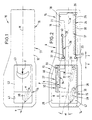
- a knife 10 has a knife housing 11, which from an upper housing shell 12 and from one lower housing shell 13 is composed. Both housing shells 12, 13 face each other with their hollow sides and are more appropriate in unspecified Attached to each other (e.g. detachable), for example by screwing or by clipping.
- Knife blade 14 Inside the cavity 46 of the lower shell 13 is a knife blade 14 Blade carrier 15 along the central axis labeled M, in the extension direction x and in the retraction direction z, translationally displaceable.
- the a partially visible main area (broad area) of the Knife blade 14 bears the reference number 47.
- the blade carrier 15 points in the area of the rear Handle extension 16 of the knife housing 11 a Guide extension 17 with a guide projection 18, which on the rectilinear inner surface 19 of the knife housing 11 is performed.
- the guide extension 17 On its two long sides the guide extension 17 each form a longitudinal recess 20, 21.
- the blade carrier has an eyelet 22 into which the front End 23 of a tension spring 24 is hooked.
- the back End 25 of the tension spring 24 is on one of the knife housing 11 formed pin 26 attached.
- the blade carrier 15 is partially from an operating part 27 subordinate, which is a separate Represents component.
- the actuator 27 is independent by the blade carrier 15 translationally linearly movable namely along a dash-dotted line Straight line L, which is also dash-dotted with represent central axis M an angle ⁇ forms.
- the actuating part 27 is along the straight line L. in the exit direction of the blade carrier 15 in the direction a and movable in direction e of the blade carrier 15 in the direction e.
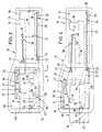
- this has two guide pins to be addressed as link pins 28 on the underside of the actuating part 27 for Project the bottom 29 of the lower housing shell 13.
- the guide pins 28 protrude in the form of slot grooves to be addressed guide grooves 30, 31, which extend straight and into the bottom 29 of the bottom Housing shell 13 are embedded.
- the two Longitudinal axes LN of the two guide grooves 30, 31 are related the central axis M also at an angle ⁇ inclined.
- the actuating part 27 has on one long side one the blade carrier 15 on its narrow side H comprehensive approach 32, shown in longitudinal section is.
- the approach 32 forms on its narrow side H of the blade carrier 15 facing the inside K a primary coupling element P, while the narrow side H of the blade support 15 is a secondary coupling element S has.
- the secondary coupling part S is according to the Fig. 2-7 from a recess on the narrow side H of the Blade carrier 15.
- the opening 36 of the recess has backwards in the direction of retreat z. So that the himself straight extending kink rod 34 in the unloaded Condition with its free end P in the undercut Can engage recess, the buckling bar 34th in the clamping point 33 a little towards the narrow side H of the blade carrier 15 arranged inclined.
- the operating part has 27 an eyelet 37 into which the front end 35 a tension spring 38 is hooked.
- the back end 39 of the tension spring 38 is on a pin 40 of the lower Housing shell 13 of the knife housing 11 attached.
- the knife 10 shown functions as follows:
- the actuating part 27 is described above Way by means of its guide pin 28 in the housing side rectilinear guide grooves 30, 31 in one Angle ⁇ led to the central axis M.
- the actuator 27 is by means of the in the longitudinal recess 21st of the extension 17 arranged tension spring 38 in held its rear starting position A.
- the actuating part 27 has an actuating recess 41 of the upper housing shell 12 accessible Push handle handle 42, which the blade carrier 15 overlaps on the top and which with a Handle recess 43 is provided.
- the arrangement is like this met that on the neck 32 of the actuating part 27th the push handle handle 42 is fastened with one long side, is cohesively connected, such that the actuating part 27 a total Blade carrier 15 encompassing a C-shaped cross section having.
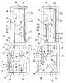
- the components 12, 13, 15, 27 and 42 form cast parts, So plastic injection or metal die-cast parts.
- Fig. 8 shows an alternative embodiment, at which, in geometrical inversion, the buckling bar 34 intrinsically elastic plastic and the blade carrier 15 is integrally formed.
- the recess is from the approach 32 of the actuator 27th educated.
Description
Die Erfindung bezieht sich auf ein Messer nach dem
Oberbegriff des Anspruchs 1.The invention relates to a knife according to the
Preamble of
Von der DE 36 22 342 A1 ist ein solches Sicherheitsmesser, ein sogenanntes Kartonmesser, bekannt, welches zum Schneiden von Verpackungskartons verwendet wird.DE 36 22 342 A1 discloses such a safety knife, a so-called cardboard knife, known which is used for cutting packaging boxes becomes.
Die hauptsächlichen Merkmale des Messers gemäß der
DE 36 22 342 A1 gestatten folgende Funktionsweise:The main features of the knife according to the
Ein translatorisch verschieblicher Klingenträger ist entgegen einer Rückstellkraft, und zwar entgegen einer Federrückstellkraft, mittels eines Betätigungsbereichs, der eine Schiebegriffhandhabe darstellt, aus dem Messergehäuse ausfahrbar und dabei in die Schneidposition der von ihm aufgenommenen Bandstahl-Wechselklinge versetzbar. Solange sich die Messerklinge in Eingriff mit dem Schneidgut (Karton) befindet, sorgt die Reibung zwischen Messerklinge und Schneidgut, also die Schneidreaktionskraft, dafür, daß der Klingenträger entgegen der Rückstellkraft einer Zugfeder in seiner ausgefahrenen Betriebsposition verbleibt. Sobald die Schneidreaktionskraft geringer ist als die Rückstellkraft der Zugfeder, zieht letztere den mit der Messerklinge versehenen Klingenträger in Einfahrrichtung in seine Schutzpostion (Ausgangsposition) innerhalb des Messergehäuses zurück.A translatable blade carrier is against a restoring force, namely against a spring restoring force, by means of an actuation area, which represents a push handle handle the knife housing can be extended and into the cutting position the interchangeable steel blade he picked up movable. As long as the knife blade is in Engagement with the material to be cut (carton) the friction between the knife blade and the material to be cut, so the cutting reaction force, making sure that the blade carrier against the restoring force of a tension spring in its extended operating position remains. As soon as the Cutting reaction force is less than the restoring force the tension spring, the latter pulls the one with the knife blade provided blade carrier in the retraction direction in its protective position (starting position) within the Knife housing back.
Das Zurückziehen bzw. Einfahren des Klingenträgers geschieht aber nur dann, wenn die Betätigungshand die Schiebegriffhandhabe losläßt. Bei dem bekannten Sicherheitsmesser gemäß der DE 36 22 342 A1 ist es zwar an sich nicht gewollt, aber dennoch ohne weiteres möglich, durch Dauerbetätigung der Schiebegriffhandhabe den Klingenträger in seiner ausgefahrenen Schneidposition festgehalten, so daß Verletzungen bei einem versehentlichen Abgleiten des Messers vom Schneidgut nicht auszuschließen sind.The retraction or retraction of the blade carrier but only happens when the operating hand Let go of the push handle handle. With the well-known safety knife according to DE 36 22 342 A1, it is on not wanted, but still possible, by continuously operating the push handle handle Blade holder in its extended cutting position detained so that accidental injuries Sliding of the knife from the material to be cut cannot be excluded are.
Ausgehend von dem eingangs beschriebenen Messer gemäß der DE 36 22 342 A1, liegt der Erfindung die Aufgabe zugrunde, das bekannte Messer hinsichtlich seiner Sicherheitsfunktion zu verbessern.Starting from the knife described above According to DE 36 22 342 A1, the invention has the object based on the well-known knife in terms of its Improve safety function.
Diese Aufgabe löst die Erfindung dadurch, daß die Betätigungshandhabe von einem relativ zum Klingenträger beweglichen gesonderten Betätigungsteil gebildet ist, welches entgegen der Ausfahrbewegung des Klingenträgers mit einer gesonderten Rückstellkraft, wie z.B. mit einer gesonderten Federrückstellkraft, belastet ist, daß Klingenträger und Betätigungsteil in ihrer Ausgangsposition durch ein primäres Kupplungselement des Betätigungsteils oder des Klingenträgers und durch ein korrespondierendes sekundäres Kupplungselement des Klingenträgers oder des Betätigungsteils nur im Ausfahrsinne des Klingenträgers auf Mitnahme bewegungsgekuppelt, jedoch im Einfahrsinne des Klingenträgers außer Eingriff miteinander sind, daß die Bewegung des Betätigungsteils im Ausfahrsinne des Klingenträgers begrenzt ist, und daß dem Klingenträger eine zusätzliche Relativbewegung in Ausfahrrichtung gestattet ist, welche die beiden Kupplungselemente außer Eingriff miteinander versetzt.The invention solves this problem in that the Operating handle from one relative to the blade carrier movable separate actuating part is formed, which counter to the extension movement of the blade carrier with a separate restoring force, e.g. with a separate spring restoring force, is loaded that Blade carrier and actuating part in their starting position by a primary coupling element of the actuating part or the blade carrier and by a corresponding secondary coupling element of the Blade carrier or the actuating part only in the direction of extension the blade carrier is motion-coupled to be carried along, however in the entry direction of the blade holder are disengaged from each other that the movement of the Operating part limited in the sense of extension of the blade carrier is, and that the blade carrier an additional Relative movement in the extension direction is permitted, which the two coupling elements out of engagement with each other added.
Im Vergleich zu dem eingangs beschriebenen Sicherheitsmesser gemäß der DE 36 22 342 A1, ist es beim erfindungsgemäs-sen Sicherheitsmesser zunächst wesentlich, daß die Betätigungshandhabe von einem relativ zum Klingenträger beweglichen gesonderten Betätigungsteil gebildet ist. Sowohl der Klingenträger als auch das gesonderte Betätigungsteil sind beim erfindungsgemäßen Messer mit einer gesonderten Kraft, vorzugsweise mit einer gesonderten Federkraft, in ihre Ausgangsposition hinein rückstellbelastet. Und zwar ist das erfindungsgemäße Betätigungsteil entgegen der Ausfahrbewegung des Klingenträgers mit einer gesonderten Federkraft rückstellbelastet.In comparison to the safety knife described at the beginning according to DE 36 22 342 A1, it is in accordance with the invention Safety knife at first essential, that the operating handle from a relative to Blade carrier movable separate operating part is formed. Both the blade carrier and the separate one Actuating part are in the invention Knife with a separate force, preferably with a separate spring force, in their starting position reset load. That is the invention Actuating part against the extension movement of the Blade carrier resiliently loaded with a separate spring force.
Eine weitere bemerkenswerte Besonderheit des erfindungsgemäßen Sicherheitsmessers besteht darin, daß Klingenträger und Betätigungsteil in ihrer zurückgestellten bzw. zurückgezogenen Ausgangsposition durch ein primäres Kupplungselement des Betätigungsteils oder des Klingenträgers und durch ein korrespondierendes sekundäres Kupplungselement des Klingenträgers oder des Betätigungsteils nur im Ausfahrsinne des Klingenträgers auf Mitnahme bewegungsgekuppelt sind, jedoch im Einfahrsinne des Klingenträgers außer Eingriff miteinander sind.Another remarkable peculiarity of the invention Safety knife is that Blade carrier and actuator in their reset or retracted starting position a primary coupling element of the actuating part or of the blade holder and by a corresponding secondary Coupling element of the blade carrier or Actuating part only in the direction of extension of the blade carrier are coupled with movement, but in the direction of entry the blade carrier out of engagement with each other are.
Diese Besonderheit bekommt erfindungsgemäß dadurch ihren wesentlichen weiterbildenden Sinn, daß die Bewegung des Betätigungsteils im Ausfahrsinne des Klingenträgers begrenzt ist, während dem Klingenträger jedoch eine zusätzliche Relativbewegung in Ausfahrrichtung gestattet ist. Diese zusätzliche Relativbewegung versetzt die beiden Kupplungselemente außer Eingriff miteinander.This peculiarity is given according to the invention their essential further education meaning that the movement of the operating part in the direction of extension of the blade carrier is limited, however, during the blade carrier an additional relative movement in the extension direction allowed is. This additional relative movement offset the two coupling elements out of engagement with each other.
Dieses bedeutet, daß bei einer Bewegung des Betätigungsteils (welches dazu beispielsweise eine Schiebegriffhandhabe aufweisen kann) im Ausfahrsinne des Klingenträgers letzterer wegen der Bewegungskupplung zwischen den beiden Kupplungselementen zum Schneidgut hin so lange vorgeschoben wird, bis die Bewegung des Betätigungsteils beispielsweise durch einen Anschlag gestoppt wird. Sobald die Messerklinge in das Schneidgut eingedrungen ist und die ziehende Schneidbewegung einsetzt, versucht die Schneidreaktionskraft, die Messerklinge (damit auch den Klingenträger) im Schneidgut festzuhalten, was die erwähnte zusätzliche Relativbewegung des Klingenträgers in Ausfahrrichtung bewirkt.This means that when the actuating part moves (which, for example, has a push handle handle can have) in the sense of extension of the blade carrier the latter because of the motion coupling between the two coupling elements towards the material to be cut is advanced until the movement of the operating part stopped for example by a stop becomes. As soon as the knife blade into the material to be cut has penetrated and the pulling cutting movement starts, tries the cutting reaction force, the knife blade (thus also the blade carrier) in the material to be cut to record what the mentioned additional relative movement of the blade carrier in the extending direction.
Diese zusätzliche Relativbewegung wird z.B. dazu genutzt, das sekundäre Kupplungselement des Klingenträgers außer Eingriff mit dem primären Kupplungselement des Betätigungsteils zu versetzen, wodurch die zunächst vorhandene, einseitig in Ausfahrrichtung des Klingenträgers vorhandene Bewegungskupplung getrennt wird. Die Schneidposition des Klingenträgers ändert sich dadurch nicht, jedenfalls dann nicht, solange die Schneidarbeit fortgesetzt wird, und die Schneidreaktionskraft dabei versucht, die Messerklinge im Schneidgut festzuhalten. This additional relative movement is e.g. to used, the secondary coupling element of the blade carrier out of engagement with the primary coupling element to move the actuating part, whereby the first existing, one-sided in the direction of extension of the blade carrier existing motion clutch is disconnected. The This changes the cutting position of the blade holder not, at least not as long as the cutting work continues, and the cutting reaction force tries to hold the knife blade in the material to be cut.
Sobald aber die Schneidarbeit beendet wird, was auch bei einem unbeabsichtigten Abgleiten vom Schneidgut der Fall ist, wird der Klingenträger von der ihm gesondert zugeordneten Federrückstellkraft in seine Schutzposition, d.h. in seine Ausgangsposition, zurückbewegt. Diese Zurückbewegung des Klingenträgers in seine Ausgangsposition erfolgt selbst dann, wenn die Bedienungshand versuchen sollte, das Betätigungsteil durch Dauerbetätigung im Ausfahrsinne des Klingenträgers zu belasten.But as soon as the cutting is finished, what even in the event of accidental sliding off the material to be cut the case is, the blade holder of the him separately assigned spring restoring force in its Protective position, i.e. to its starting position, moved back. This back movement of the blade carrier in its starting position occurs even when the Operating hand should try the actuator by permanent actuation in the direction of extension of the blade holder to charge.
Die Bestimmung "die Bewegung des Betätigungsteils im Ausfahrsinne des Klingenträgers" ist so zu definieren, daß die Gestalt, Form und Richtung dieser Bewegung gleichgültig sind, wenn nur die Bewegung des Betätigungsteils die Bewegung des Klingenträgers in Ausfahrrichtung bewirkt.The definition "the movement of the operating part in the sense of extension of the blade carrier "is to be defined that the shape, shape and direction of this movement are indifferent if only the movement of the actuating part the movement of the blade carrier in the direction of extension causes.
Eine einfache Bauform des erfindungsgemäßen Messers ist jedenfalls durch eine translatorische geradlinige Bewegung des Bewegungsteils zu erzielen.A simple design of the knife according to the invention is in any case due to a translational rectilinear To achieve movement of the moving part.
Eine Variante des erfindungsgemäßen Messers kann in einer translatorisch gekrümmten Bewegung des Betätigungsteils bestehen.A variant of the knife according to the invention can in a translationally curved movement of the actuating part consist.
Wie bereits weiter oben erwähnt, wird die Bewegung des Betätigungsteils im Ausfahrsinne des Klingenträgers in einfacher Weise von einem Anschlag begrenzt, den zweckmäßig das Messergehäuse bildet. As mentioned earlier, the movement of the operating part in the direction of extension of the blade carrier limited in a simple manner by a stop, the expediently forms the knife housing.
In weiterer Ausgestaltung der Erfindung wird durch die gemeinsame Bewegung des Betätigungsteils und des Klingenträgers im Ausfahrsinne des letzteren eine Schaltbewegung vorbereitet, mittels welcher die beiden Kupplungselemente voneinander trennbar sind. Vorteilhaft geschieht dies so, daß die beiden Kupplungselemente quer zu ihren Bewegungsbahnen voneinander trennbar sind.In a further embodiment of the invention the common movement of the actuator and the Blade holder in the exit sense of the latter one Switching movement prepared, by means of which the two Coupling elements are separable. Advantageous this happens so that the two coupling elements separable from each other across their trajectories are.
Im einzelnen kann die Schaltbewegung dadurch vorbereitet werden, daß die Bewegungsbahnen der beiden Kupplungselemente oder die Bewegungsbahnen von Klingenträger und Betätigungsteil einschließlich der ihnen zugeordneten Kupplungselemente unterschiedlich verlaufen.In particular, the switching movement can be prepared that the trajectories of the two Coupling elements or the movement paths of blade carriers and actuating part including those assigned to them Coupling elements run differently.
Eine vorteilhafte Art, die Schaltbewegung vorzubereiten, besteht in der Anwendung einer Kulissensteuerung, welche insbesondere dem Betätigungsteil und dem Messergehäuse zugeordnet sein kann.An advantageous way to prepare the switching movement consists in the use of a backdrop control, which in particular the actuator and the Knife housing can be assigned.
Entsprechend einem bevorzugten Ausführungsbeispiel ist mindestens ein Kulissenschlitz oder mindestens eine Führungsnut mit jeweils zugeordnetem Führungszapfen vorgesehen, wobei der Längsverlauf des Kulissenschlitzes oder der Führungsnut in Richtung des Betätigungsteils bezüglich der Ausfahrrichtung des Klingenträgers divergiert.According to a preferred embodiment is at least one slot or at least one Guide groove with a respective assigned guide pin provided, the longitudinal course of the slot slot or the guide groove in the direction of the actuating part with respect to the direction of extension of the blade carrier diverges.
Eine Ausführungsform kann darin bestehen, daß sich der Kulissenschlitz oder die Führungsnut entlang einer sich quer zu einer Hauptfläche der Messerklinge angeordneten Ebene erstreckt. Eine andere vorteilhafte Ausführungsform besteht z.B. darin, daß sich der Kulissenschlitz oder die Führungsnut entlang einer in oder parallel zu einer Hauptfläche der Messerklinge angeordneten Ebene erstrecken.One embodiment can be that the link slot or the guide groove along one arranged transversely to a main surface of the knife blade Level extends. Another advantageous embodiment e.g. in that the backdrop slot or the guide groove along an in or parallel arranged to a main surface of the knife blade Extend level.
Eine andere erfindungsgemäße Ausführungsvariante besteht darin, daß die dem Betätigungsteil zugeordnete Kulissensteuerung zwei Kulissenschlitze bzw. Führungsnuten mit zwei korrespondierenden Führungszapfen zur Erzeugung der Schaltbewegung aufweist. Zweckmäßig ist dabei der jeweilige Kulissenschlitz oder die Führungsnut vom Messergehäuse gebildet, während der jeweilige Führungszapfen vom Betätigungsteil gebildet ist.Another embodiment variant according to the invention consists in that the assigned to the actuating part Link control two link slots or guide grooves with two corresponding guide pins for Has generation of the switching movement. Is expedient the respective link slot or the guide groove formed by the knife housing while the respective Guide pin is formed by the actuating part.
Eine besonders wesentliche erfindungsgemäße Ausführungsform besteht darin, daß die Schaltbewegung zur Trennung der beiden Kupplungselemente voneinander vorbereitend zunächst nur eine potentielle Federenergie erzeugt, die erst im Verlauf der zusätzlichen Relativbewegung des Klingenträgers in Ausfahrrichtung wirksam wird.A particularly essential embodiment of the invention is that the switching movement to Preparatory separation of the two coupling elements initially just a potential spring energy generated that only in the course of the additional relative movement of the blade carrier effective in the direction of extension becomes.
Und zwar wird von der gemeinsamen Bewegung von Betätigungsteil und Klingenträger eine Bewegung abgeleitet, welche dazu dient, ein Federelement aufzuladen. Sobald nun der durch die Schneidreaktionskraft bedingte zusätzliche Ausfahrweg des Klingenträgers ein bestimmtes Maß erreicht hat, geraten die beiden Kupplungselemente außer Eingriff, so daß die zuvor erzeugte potentielle Federenergie in der Lage ist, eine Trennbewegung herbeizuführen, die sich zumindest auf ein Kupplungselement bezieht und beide Kupplungselemente voneinander distanziert. Und zwar erfolgt die Distanzierung derart, daß die von Klingenträger und Bedienungsteil gelagerten beiden Kupplungselemente sich aneinander vorbeibewegen können, falls sich die Schneidreaktionskraft in einem solchen Maße verringert, daß die Federrückstellkraft in der Lage ist, den Klingenträger in seine zurückgezogene Ausgangsposition zu versetzen. Andererseits soll die Distanzierung der beiden Kupplungselemente auch die Möglichkeit schaffen, daß unabhängig von der Position des Klingenträgers das losgelassene Betätigungselement von der diesem zugeordneten Federrückstellkraft in seine Ausgangsposition zurückbewegt werden kann.That is from the joint movement of the actuating part and blade carrier derived a movement which serves to charge a spring element. As soon as the one caused by the cutting reaction force additional extension path of the blade carrier a certain Has reached dimension, the two coupling elements disengaged so that the potential previously generated Spring energy is capable of a separating movement bring about, at least on a coupling element relates and both coupling elements from each other distant. The distance is done in such a way that those stored by the blade carrier and operating part two coupling elements move past each other can, if the cutting reaction force in one reduced to such an extent that the spring return force in is able to retract the blade carrier into its Starting position to move. On the other hand, the Distance between the two coupling elements also Possibility to create that regardless of position the blade carrier the released actuator of the spring restoring force assigned to it in its starting position can be moved back.
In weiterer Ausgestaltung der Erfindung ist eines der beiden Kupplungselemente von einer Aussparung und das andere der beiden Kupplungselemente von einem mit der Aussparung verrastbaren Vorsprung eines Druckübertragungselements gebildet.In a further embodiment of the invention, one is of the two coupling elements from a recess and the other of the two coupling elements with one the recess lockable projection of a pressure transmission element educated.
Das Druckübertragungselement (oder allgemeiner: Kraftübertragungselement) kann beispielsweise von einer kulissengesteuerten und/oder federbelasteten Klinke (Druckklinke oder Zugklinke) gebildet sein, welche zu Beginn der zusätzlichen Relativbewegung des Klingenträgers in Ausfahrrichtung aus der Aussparung ausgerastet wird. Grundsätzlich ist es gleich, ob das Übertragungselement dem Betätigungsteil bzw. die Aussparung dem Klingenträger oder in umgekehrter Weise dem Klingenträger oder dem Betätigungsteil zugeordnet sind.The pressure transmission element (or more generally: Power transmission element) can, for example, by a link-controlled and / or spring-loaded jack (Pressure pawl or pull pawl) are formed, which too Start of the additional relative movement of the blade carrier disengaged from the recess in the direction of extension becomes. Basically, it is the same whether the transmission element the actuating part or the recess Blade carrier or in reverse the blade carrier or are assigned to the actuating part.
Eine einfache sichere unkomplizierte Bauform ist dadurch gegeben, daß das Druckübertragungselement einen einseitig eingespannten Knickstab bildet, dessen bewegliches freies Ende den Vorsprung als primäres oder sekundäres Kupplungselement darstellt, welches mit einer Aussparung als sekundärem oder primärem Kupplungselement zusammenwirkt. Dabei hat die Erfindung auch die Möglichkeit vorgesehen, daß in den freien Knickstab bereits eine besonders wirksame Federkraft integriert ist, indem der freie Knickstab aus einem Federmetall, insbesondere aus Federstahl, besteht.A simple safe uncomplicated design is given that the pressure transmission element a one side clamped buckling bar forms its movable free end the lead as primary or secondary Coupling element, which with a Recess as a secondary or primary coupling element interacts. The invention also has the Possibility provided that already in the free buckling bar a particularly effective spring force integrated is by making the free buckling bar from a spring metal, in particular from spring steel.
Eine in gewissen Anwendungsfällen ebenfalls zu wählende Alternative kann darin bestehen, daß der Knickstab dem Klingenträger oder dem Betätigungsteil stoffschlüssig angeformt ist und insbesondere aus einem elastische Eigenschaften aufweisenden Kunststoff besteht.This also applies to certain applications Choosing alternative can be that the Buckling bar the blade carrier or the actuating part is integrally formed and in particular from one plastic has elastic properties.
Eine besonders praxisgerechte erfindungsgemäße Ausführungsform besteht darin, daß Klingenträger und Betätigungsteil nebeneinander in einer zu einer Hauptfläche der Messerklinge parallelen oder geneigten Ebene angeordnet sind.A particularly practical one according to the invention Embodiment is that blade carriers and Actuator side by side in one to a main surface the knife blade parallel or inclined plane are arranged.
In diesem Zusammenhang ist es zweckmäßig, das Betätigungsteil so zu gestalten, daß dieses an einer Längsseite einen den Klingenträger an seiner Schmalseite übergreifenden Ansatz bildet, welcher an seiner der Schmalseite des Klingenträgers zugewandten Innenseite das eine oder das andere Kupplungselement bildet, während die Schmalseite des Klingenträgers das andere oder das eine Kupplungselement trägt. In this context, it is expedient for the actuating part to be designed so that this on a Long side one the blade carrier on its narrow side overarching approach, which at its the inner side facing the narrow side of the blade carrier forms one or the other coupling element, while the narrow side of the blade carrier is the other or that carries a coupling element.
Eine erfindungsgemäße Weiterentwicklung besteht darin, daß an dem vorbeschriebenen Ansatz die Schiebegriffhandhabe mit einer Längsseite befestigt, insbesondere stoffschlüssig angebunden ist, derart, daß das Betätigungsteil insgesamt einen den Klingenträger umgreifenden C-förmigen Querschnitt aufweist.A further development according to the invention exists in that the push handle handle on the above-described approach attached with one long side, in particular is integrally connected, such that the actuating part a total of one encompassing the blade carrier C-shaped cross section.
In den Zeichnungen sind bevorzugte Ausführungsbeispiele
entsprechend der Erfindung mehr schematisch dargestellt,
es zeigt,
Ein Messer 10 weist ein Messergehäuse 11 auf, welches
aus einer oberen Gehäuseschale 12 und aus einer
unteren Gehäuseschale 13 zusammengesetzt ist. Beide Gehäuseschalen
12, 13 weisen mit ihren Hohlseiten zueinander
und sind in nicht näher gezeigter zweckmäßiger
Weise aneinander (z.B.lösbar) befestigt, beispielsweise
durch Verschraubung oder durch Verklipsung. A
Innerhalb des Hohlraums 46 der unteren Gehäuseschale
13 ist ein eine Messerklinge 14 aufnehmender
Klingenträger 15 entlang der mit M bezeichneten Mittelachse,
und zwar in Ausfahrrichtung x und in Rückzugsrichtung
z, translatorisch geradlinig verschiebbar. Die
eine teilweise sichtbare Hauptfläche (Breitfläche) der
Messerklinge 14 trägt die Bezugsziffer 47.Inside the
Der Klingerträger 15 weist im Bereich der rückwärtigen
Griffverlängerung 16 des Messergehäuses 11 einen
Führungsfortsatz 17 mit einem Führungsansatz 18 auf,
welcher an der geradlinigen Innenfläche 19 des Messergehäuses
11 geführt ist. An seinen beiden Längsseiten
bildet der Führungsfortsatz 17 jeweils eine Längsaussparung
20, 21.The
Etwa dort, wo der Führungsfortsatz 17 sich an den
vorderen Bereich des Klingenträgers 15 anschließt, bildet
der Klingenträger eine Öse 22, in welche das vordere
Ende 23 einer Zugfeder 24 eingehakt ist. Das rückwärtige
Ende 25 der Zugfeder 24 ist an einem vom Messergehäuse
11 gebildeten Zapfen 26 befestigt.For example, where the
Der Klingenträger 15 ist teilweise von einem Betätigungsteil
27 unterlagert, welches ein gesondertes
Bauteil darstellt. Das Betätigungsteil 27 ist unabhängig
vom Klingenträger 15 translatorisch geradlinig bewegbar
und zwar entlang einer strichpunktiert dargestellten
Geraden L, welche mit der ebenfalls strichpunktiert
dargestellen Mittelachse M einen Winkel α
bildet. The
Entlang der Geraden L ist das Betätigungsteil 27
im Ausfahrsinne des Klingenträgers 15 in Richtung a und
im Einfahrsinne des Klingenträgers 15 in Richtung e beweglich.The actuating
Zur Führung des Betätigungsteils 27 weist dieses
zwei als Kulissenzapfen anzusprechende Führungszapfen
28 auf, welche unterseitig des Betätigungsteils 27 zum
Boden 29 der unteren Gehäuseschale 13 vorragen.
Zugleich ragen die Führungszapfen 28 in als Kulissennuten
anzusprechende Führungsnuten 30, 31 hinein, welche
sich geradlinig erstrecken und in den Boden 29 der unteren
Gehäuseschale 13 eingelassen sind. Die beiden
Längsachsen LN der beiden Führungsnuten 30, 31 sind bezüglich
der Mittelachse M ebenfalls unter einem Winkel
α geneigt.To guide the
Das Betätigungsteil 27 besitzt an einer Längsseite
einen den Klingenträger 15 an dessen Schmalseite H
übergreifenden Ansatz 32, der im Längsschnitt dargestellt
ist. Der Ansatz 32 bildet an seiner der Schmalseite
H des Klingenträgers 15 zugewandten Innenseite K
ein primäres Kupplungselement P, während die Schmalseite
H des Klingenträgers 15 ein sekundäres Kupplungselement
S aufweist.The actuating
Gemäß den Fig. 2-7 ist im Ansatz 32 an einer Einspannstelle
33 ein einseitig eingespannter Knickstab 34
aus Federstahl gehalten, dessen freies Ende das vorerwähnte
primäre Kupplungsteil P bildet. 2-7 is in the
Das sekundäre Kupplungsteil S besteht gemäß den
Fig. 2-7 aus einer Aussparung an der Schmalseite H des
Klingenträgers 15. Die Öffnung 36 der Aussparung weist
nach rückwärts in Rückzugsrichtung z. Damit der sich
geradlinig erstreckende Knickstab 34 im unbelasteten
Zustand mit seinem freien Ende P in die hinterschnittene
Aussparung eingreifen kann, ist der Knickstab 34
in der Einspannstelle 33 ein wenig in Richtung Schmalseite
H des Klingenträgers 15 geneigt angeordnet.The secondary coupling part S is according to the
Fig. 2-7 from a recess on the narrow side H of the
An seinem rückwärtigen Ende weist das Betätigungsteil
27 eine Öse 37 auf, in welche das vordere Ende 35
einer Zugfeder 38 eingehakt ist. Das rückwärtige Ende
39 der Zugfeder 38 ist an einem Zapfen 40 der unteren
Gehäuseschale 13 des Messergehäuses 11 befestigt.At its rear end, the operating part has
27 an
Das dargestellte Messer 10 funktioniert folgendermaßen:The
Der in der unteren Gehäuseschale 13 gelagerte und
gegenüber dem Messergehäuse 11 nur geradlinig translatorisch
bewegliche Klingenträger 15 wird mit Hilfe der
Zugfeder 24 in seiner Ausgangsposition A gehalten.The stored in the
Das Betätigungsteil 27 ist in vorbeschriebener
Weise mittels der seiner Führungszapfen 28 in den gehäuseseitigen
geradlinigen Führungsnuten 30, 31 in einem
Winkel α zur Mittelachse M geführt. Das Betätigungsteil
27 wird mittels der in der Längsaussparung 21
des Führungsfortsatzes 17 angeordneten Zugfeder 38 in
seiner rückwärtigen Ausgangsposition A gehalten. The actuating
Zum Betätigungsteil 27 gehört eine über eine Betätigungsaussparung
41 der oberen Gehäuseschale 12 zugängliche
Schiebegriffhandhabe 42, welche den Klingenträger
15 oberseitig übergreift und welche mit einer
Griffmulde 43 versehen ist. Dabei ist die Anordnung so
getroffen, daß an dem Ansatz 32 des Betätigungsteils 27
die Schiebegriffhandhabe 42 mit einer Längsseite befestigt,
beispielsweise stoffschlüssig angebunden ist,
derart, daß das Betätigungsteil 27 insgesamt einen den
Klingenträger 15 umgreifenden C-förmigen Querschnitt
aufweist.The actuating
Wenn der die Messerklinge 14 tragende Klingenträger
15 in Schneidposition versetzt werden soll, wird
auf die Griffmulde 43 eine Betätigungskraft F ausgeübt.
Diese Betätigungskraft F bewirkt zunächst, daß das Betätigungsteil
27 ein wenig in Richtung a vorgeschoben
wird, so daß das vordere Ende (primäres Kupplungselement
P) des Betätigungsteils 27 in die Aussparung
(sekundäres Kupplungselement S) des Klingenträgers 15
eingreift, wie aus Fig. 3 ersichtlich ist.If the blade carrier carrying the
Bei weiterer Einwirkung der Betätigungskraft F und
Verschiebung des Betätigungsteils 27 in Richtung a
schlagen schließlich die beiden Führungszapfen 28 des
Betätigungsteils 27 an den vorderen Innenflächen 44 der
beiden Führungsnuten 30, 31 an. Die vorderen Innenflächen
44 der schräggeneigten Führungsnuten 30, 31 bilden
demnach Anschläge für die Bewegungsbegrenzung des Betätigungsteils
27 im Ausfahrsinne des Klingenträgers 15,
wie Fig. 4 im einzelnen zeigt. With further action of the actuating force F and
Displacement of the
Da sich, wie ein Vergleich zwischen Fig. 3 und
Fig. 4 zeigt, das Betätigungsteil 27 gegenüber dem
Klingenträger 15 nach oben bewegt, wird der Knickstab
34 unter Bildung potentieller Federenergie gebogen,
während das freie Ende des Knickstabes 34 in der Aussparung
formschlüssig gehalten ist.As a comparison between Fig. 3 and
Fig. 4 shows the actuating
Wenn jetzt die Messerklinge 14 in das Schneidgut
45 eingreift und das gesamte Messer 10 eine Schneidbewegung
in Schneidrichtung C gemäß Fig. 5 durchführt,
versucht eine Schneidreaktionskraft die im Klingenträger
15 formschlüssig aufgenommene Messerklinge 14 im
Schneidgut 45 festzuhalten. Dieses hat zur Folge, daß
der Klingenträger 15 eine zusätzliche Relativbewegung
mit dem Weg R in Ausfahrrichtung x vollführen kann,
während das Betätigungsteil 27 mittels seiner Führungszapfen
28 an den Anschlägen 44 der beiden schräg geneigten
Führungsnuten 30, 31 oder an einem anderen Anschlag
des Messergehäuses 11 blockiert ist.If now the
Durch diese zusätzliche Relativbewegung mit dem
Weg R in Ausfahrrichtung x werden die beiden Kupplungselemente
P und S außer Eingriff versetzt, wobei sich
der Knickstab 34 entspannt und dabei streckt, so daß
das freie Ende (primäres Kupplungselement P) sich auf
einer Bewegungsbahn seitlich neben der Aussparung
(sekundäres Kupplungselement S) befindet.Through this additional relative movement with the
Path R in the extension direction x become the two coupling elements
P and S disengaged, where
the buckling
Falls die Schneidbewegung des Messers 10 in
Schneidrichtung C fortgesetzt wird, während sich die
Messerklinge 14 im Schneidgut 45 befindet, kann die
Schiebegriffhandhabe 42 losgelassen werden, so daß das
Betätigungsteil 27 in seine Ausgangsposition (vgl. Ausgangsposition
A gemäß Fig. 2) zurückkehren kann, wie
Fig. 6 zeigt.If the cutting movement of the
Sobald aber die Messerklinge 14 das Schneidgut 45
verläßt, also auch dann, wenn die Messerklinge 14 versehentlich
vom Schneidgut 45 abgleitet, so daß die
Schneidreaktionskraft nicht mehr vorhanden ist, zieht
die Zugfeder 24 den Klingenträger 15 mit der Messerklinge
14 in die geschützte Ausgangsposition A gemäß
Fig. 2 zurück.But as soon as the
Dieses Zurückziehen des Klingenträgers 15 in die
Ausgangsposition A erfolgt auch dann, wenn der Klingenträger
15 versehentlich in seiner vorderen Position belassen
wurde, wie ein Vergleich zwischen den beiden
Fig. 5 und 7 ohne weiteres ergibt.This retraction of the
Die Bauteile 12, 13, 15, 27 und 42 bilden Gußteile,
also Kunststoffspritzguß- oder Metalldruckgußteile.The
Fig. 8 zeigt eine alternative Ausführungsform, bei
welcher in geometrischer Umkehrung der Knickstab 34 aus
eigenelastischem Kunststoff besteht und dabei dem Klingenträger
15 stoffschlüssig angeformt ist. Die Aussparung
wird dabei vom Ansatz 32 des Betätigungsteils 27
gebildet.Fig. 8 shows an alternative embodiment, at
which, in geometrical inversion, the buckling
Claims (28)
- Knife (10) having a knife housing (11), in which a blade carrier (15) holding a knife blade (14) is guided so as to be relatively movable, which blade carrier is displaceable by means of an actuating handle (42) counter to restoring force (tension spring 24) from a normal position (A), in which the knife blade (14) is retracted and protected in the knife housing (11), into a cutting position, in which the knife blade (14) projects from the knife housing (11), characterized in that the actuating handle (42) is formed by a separate actuating part (27), which is movable relative to the blade carrier (15) and is loaded counter to the movement of extension of the blade carrier (15) by a separate restoring force (38), that blade carrier (15) and actuating part (27) in their normal position (A) are motionally coupled by a primary coupling element (P) of the actuating part (27) or of the blade carrier (15) and by a corresponding second coupling element (S) of the blade carrier (15) or of the actuating part (27) for driving only in the direction of extension (x) of the blade carrier (15) but are mutually disengaged in the direction of retraction of the blade carrier (15), that the movement of the actuating part (27) in the direction of extension of the blade carrier (15) is limited, and that the blade carrier (15) is allowed an additional relative movement in extension direction (x), which moves the two coupling elements (P, S) out of engagement with one another.
- Knife according to claim 1, characterized by a translatory rectilinear movement of the blade carrier (15).
- Knife according to claim 1 or according to claim 2, characterized by a translatory rectilinear movement of the actuating part (27).
- Knife according to claim 1 or according to claim 2, characterized by a translatory curved movement of the actuating part (27).
- Knife according to one of claims 1 to 4, characterized in that the movement of the actuating part (27) in the direction of extension of the blade carrier (15) is limited by a stop (44).
- Knife according to claim 5, characterized in that the stop (44) is formed by the knife housing (11).
- Knife according to one of claims 1 to 6, characterized in that the joint movement of the actuating part (27) and the blade carrier (15) in the direction of extension of the latter (15) is a preliminary to a switching movement, by means of which the two coupling elements (P, S) are separable from one another.
- Knife according to claim 7, characterized in that the two coupling elements (P, S) are separable from one another at right angles to their paths of motion.
- Knife according to claim 7 or according to claim 8, characterized in that the preliminary to the switching movement is a different course of the paths of motion of the two coupling elements (P, S).
- Knife according to claim 7 or according to claim 8, characterized in that the preliminary to the switching movement is a different course of the paths of motion of blade carrier (15) and actuating part (27) including their associated coupling elements (S, P).
- Knife according to one of claims 7 to 10, characterized in that the preliminary to the switching movement is a link control (30, 31, 28).
- Knife according to claim 11, characterized in that the link control (30, 31, 28) is associated with the actuating part (27) and the knife housing (11).
- Knife according to claim 12, characterized by at least one link slot or by at least one guiding groove (30, 31) with, in each case; associated guide pins (28), wherein the longitudinal extension of the link slot or of the guiding groove (30, 31) in direction (a) of the actuating part (27) diverges relative to the direction of extension (x) of the blade carrier (15).
- Knife according to claim 13, characterized in that the link slot or the guiding groove (30, 31) extends along a plane disposed at right angles to a main surface (47) of the knife blade (14).
- Knife according to claim 13, characterized in that the link slot or the guiding groove (30, 31) extends along a plane disposed in or parallel to the main surface (47) of the knife blade (14).
- Knife according to one of claims 12 to 15, characterized in that the link control (30, 31, 28) associated with the actuating part (27) comprises two link slots and/or guiding grooves (30, 31) with two corresponding guide pins (28) for producing the switching movement.
- Knife according to one of claims 12 to 16, characterized in that the respective link slot or the respective guiding groove (30, 31) is formed by the knife housing (11), while the respective guide pin (28) is formed by the actuating part (27).
- Knife according to one of claims 7 to 17, characterized in that the switching movement for separating the two coupling elements (P, S) from one another generates as a preliminary initially only a potential spring energy, which becomes effective only in the course of the additional relative movement of the blade carrier (15) in extension direction (x).
- Knife according to one of claims 1 to 18, characterized in that one of the two coupling elements (S) is formed by a recess and the other of the two coupling elements (P) is formed by a projection of a load or pressure transmission element (34), which projection is latchable with the recess.
- Knife according to claim 19, characterized in that the pressure transmission element forms a strut (34), which is clamped in at one end and the movable free end of which is the projection serving as primary (P) or secondary coupling element, which cooperates with a recess serving as secondary (S) and primary coupling element.
- Knife according to claim 20, characterized in that the strut (34) is made of spring metal, in particular of spring steel.
- Knife according to claim 20, characterized in that the strut (34) is formed cohesively on the blade carrier (15) or on the actuating part (27) and is made in particular of a plastics material having elastic properties.
- Knife according to one of claims 19 to 22, characterized in that the recess is provided on the blade carrier (15) or on the actuating part (27).
- Knife according to claim 23, characterized in that the recess is formed on the blade carrier (15) or on the actuating part (27).
- Knife according to one of claims 1 to 24, characterized in that blade carrier (15) and actuating part (27) are disposed adjacent to one another in planes parallel to the main surfaces (47) of the knife blade (14).
- Knife according to claim 24, characterized in that blade carrier (15) and actuating part (27) are disposed adjacent to one another in planes inclined relative to the main surfaces (47) of the knife blade (14).
- Knife according to claim 25 or according to claim 26, characterized in that the actuating part (27) at one longitudinal side forms a projection (32), which overlaps the blade carrier (15) at its narrow side (H) and which at its inner side (K) directed towards the narrow side (H) of the blade carrier (15) forms the one (P) or the other (S) coupling element, while the narrow side (H) of the blade carrier (15) carries the other (S) or the one (P) coupling element.
- Knife according to claim 27, characterized in that the sliding handle (42) is fastened, in particular cohesively joined, by one longitudinal side to the projection (32) in such a way that the actuating part (27) has a C-shaped cross section encompassing the blade carrier (15).
Applications Claiming Priority (2)
| Application Number | Priority Date | Filing Date | Title |
|---|---|---|---|
| DE19723279 | 1997-06-04 | ||
| DE19723279A DE19723279C1 (en) | 1997-06-04 | 1997-06-04 | Knife for e.g. cutting of packaging cartons |
Publications (4)
| Publication Number | Publication Date |
|---|---|
| EP0882553A2 EP0882553A2 (en) | 1998-12-09 |
| EP0882553A3 EP0882553A3 (en) | 1998-12-23 |
| EP0882553B1 true EP0882553B1 (en) | 2002-08-14 |
| EP0882553B8 EP0882553B8 (en) | 2005-08-31 |
Family
ID=7831285
Family Applications (1)
| Application Number | Title | Priority Date | Filing Date |
|---|---|---|---|
| EP98105812A Expired - Lifetime EP0882553B8 (en) | 1997-06-04 | 1998-03-31 | Knife |
Country Status (7)
| Country | Link |
|---|---|
| US (1) | US6148520A (en) |
| EP (1) | EP0882553B8 (en) |
| JP (1) | JP3409177B2 (en) |
| CN (1) | CN1091405C (en) |
| DE (2) | DE19723279C1 (en) |
| ES (1) | ES2181081T3 (en) |
| HK (1) | HK1016529A1 (en) |
Families Citing this family (51)
| Publication number | Priority date | Publication date | Assignee | Title |
|---|---|---|---|---|
| DE19915934C1 (en) * | 1999-04-09 | 1999-12-09 | Beermann Kg Martor Argentax | Hand knife with retractable blade |
| US6560873B1 (en) * | 1999-11-12 | 2003-05-13 | Mel Wayne Ortner | Automatic safety knife |
| FR2810574B1 (en) | 2000-06-27 | 2002-10-31 | Mure & Peyrot | AUTOMATICALLY RETRACTABLE BLADE CUTTER |
| FR2826898B1 (en) | 2001-07-06 | 2003-09-19 | Gerard Tremblay | RETRACTABLE BLADE CUTTING DEVICE |
| DE10208345C1 (en) * | 2002-02-27 | 2003-08-21 | Beermann Kg Martor Argentax | Cutting knife has safety mechansim for automatic return of blade carrier for cutting blade into retracted position within knife housing |
| US7467735B2 (en) * | 2004-10-29 | 2008-12-23 | Minuteman International, Inc. | Proportioning container |
| US20060130338A1 (en) * | 2004-12-17 | 2006-06-22 | Dzubak Donald J | Disposable box cutter |
| DE102004063045B3 (en) * | 2004-12-22 | 2006-06-08 | Martor Kg | knife |
| DE102004063046B3 (en) * | 2004-12-22 | 2006-03-09 | Martor Kg | Cutting knife, has motion converter arranged between operating part and blade carrier and initiating additional relative movement between carrier and part, where movement separates primary coupling unit from secondary coupling unit |
| DE102005015962B3 (en) * | 2005-04-07 | 2006-10-19 | Wietscher, Norbert | Safety cutting device comprises a blade held in a holder which pivots or swings out from a housing so that the blade can be exchanged without injury |
| US7797836B2 (en) * | 2005-08-02 | 2010-09-21 | The Stanley Works | Compact utility knife |
| US7316070B2 (en) * | 2005-11-15 | 2008-01-08 | Irwin Industrial Tool Company | Self-retracting utility knife |
| US20070157765A1 (en) * | 2006-01-09 | 2007-07-12 | Gabe Neiser | Package opener |
| JP4851242B2 (en) * | 2006-06-06 | 2012-01-11 | オルファ株式会社 | Safety cutter knife |
| US20080222900A1 (en) * | 2007-03-16 | 2008-09-18 | Anthony Lee | Apparatus for Emergency Seatbelt Release |
| ATE514533T1 (en) | 2007-04-16 | 2011-07-15 | Adco Ind A Subsidiary Of Dallco Marketing Inc | CUTTING RIGID AND SEMI-RIGID MATERIAL |
| DE102007052060A1 (en) | 2007-10-30 | 2009-05-07 | Martor Kg | knife |
| US8752297B2 (en) * | 2008-01-31 | 2014-06-17 | Martor Kg | Knife |
| DE102008007090B3 (en) * | 2008-01-31 | 2009-05-07 | Martor Kg | Craft knife designed for safe operation, has blade carrier swinging about axis fixed relative to casing, with spring bias for safe retraction after cutting |
| DE102008019441A1 (en) * | 2008-04-17 | 2009-10-22 | Martor Kg | knife |
| US7797838B2 (en) * | 2008-03-18 | 2010-09-21 | Taylor Brands, Llc | Retractable blade knife with opening assisted mechanism |
| US8732957B2 (en) * | 2008-04-17 | 2014-05-27 | Martor Kg | Retractile-blade utility knife |
| DE102009050380A1 (en) | 2009-10-22 | 2011-04-28 | Martor Kg | knife |
| US9840013B2 (en) | 2008-04-29 | 2017-12-12 | Pacific Handy Cutter, Inc. | Safety cutter with blade change/storage mechanism |
| US8201336B2 (en) | 2008-05-02 | 2012-06-19 | Olympia Tools International, Inc. | Retractable utility knife |
| US20090277016A1 (en) * | 2008-05-07 | 2009-11-12 | Yuewei Wu | Utility knife with an auto-retractable blade |
| US8695221B2 (en) | 2008-08-21 | 2014-04-15 | Wen Hao | Utility knife with extended travel carriage |
| US8056241B2 (en) * | 2008-10-13 | 2011-11-15 | ADCO Industries—Technologies, L.P. | Utility cutter |
| CA2752329C (en) * | 2009-02-19 | 2017-05-30 | Liqui-Box Corporation | Dual-blade film-cutting device |
| US8375588B2 (en) * | 2009-04-27 | 2013-02-19 | Allway Tools, Inc. | Automatically retracting safety carton cutter |
| US8307556B2 (en) | 2009-06-19 | 2012-11-13 | ADCO Industries—Technologies, L.P. | Utility cutter |
| DE102010023680A1 (en) | 2010-06-14 | 2011-12-15 | Martor Kg | knife |
| DE102011007234B3 (en) * | 2011-04-12 | 2012-09-20 | Martor Kg | Safety Knife |
| US8732956B2 (en) | 2011-06-15 | 2014-05-27 | Aaron Paul McGushion | Safety locking mechanism for a utility knife |
| CN202895248U (en) * | 2012-03-23 | 2013-04-24 | 上海美瑞实业有限公司 | Safe cutting knife |
| US8769826B2 (en) * | 2012-07-11 | 2014-07-08 | Yuewei Wu | Cutting device |
| TWI466763B (en) * | 2012-08-21 | 2015-01-01 | Hacksaw & Knife Manufactory Co Ltd | The blade automatically retracts the utility knife |
| US8782909B1 (en) | 2013-02-12 | 2014-07-22 | ADCO Industries—Technologies, L.P. | Utility cutter |
| DE102014208473B4 (en) * | 2014-05-06 | 2019-06-19 | Martor Kg | Knife with automatic blade reset |
| US10814505B2 (en) * | 2014-05-06 | 2020-10-27 | Martor Kg | Knife with automatic blade retraction |
| CN104654308B (en) * | 2015-01-09 | 2017-01-25 | 浙江理工大学 | Disposal device for animal carcass |
| TWM511938U (en) * | 2015-08-21 | 2015-11-11 | Kantas Products Co Ltd | Spring assisted knife controlling pop-up and retraction of blade at the same side of knife handle |
| US9808941B2 (en) * | 2016-01-15 | 2017-11-07 | Klever Kutter Llc | Safety utility knife assemblies, and components for use within safety utility knifes |
| US10300615B2 (en) | 2016-04-06 | 2019-05-28 | Earl Votolato | Utility knife with improved safety features |
| US10245736B2 (en) * | 2017-04-28 | 2019-04-02 | Orange Hardware Company | Automatically retractable cutter |
| DE202017104154U1 (en) | 2017-07-12 | 2017-11-03 | Orange Hardware Company | Cuttermesser |
| US10632964B2 (en) | 2017-07-29 | 2020-04-28 | Wilson Gutierrez | Seatbelt buckle with built-in cutter |
| US20190031135A1 (en) * | 2017-07-29 | 2019-01-31 | Wilson Gutierrez | Seat Belt Buckle With Built-in Cutter |
| US11097434B2 (en) * | 2017-12-21 | 2021-08-24 | Mark Gordon Hooper | Utility knife |
| DE102018117203B4 (en) * | 2018-07-17 | 2024-02-01 | Martor Kg | Knife |
| DE102019131546A1 (en) * | 2019-11-21 | 2021-05-27 | Martor Kg | knife |
Family Cites Families (6)
| Publication number | Priority date | Publication date | Assignee | Title |
|---|---|---|---|---|
| US3999290A (en) * | 1976-03-15 | 1976-12-28 | Wood Jess W | Safety knife |
| DE3622342A1 (en) * | 1986-07-03 | 1988-01-14 | Beermann Kg Martor Argentax | KNIFE |
| DE4310037C1 (en) * | 1993-03-27 | 1993-12-09 | Beermann Kg Martor Argentax | Knife with automatically retractable blade - has capacitive acceleration sensor in hollow handle coupled to electromagnetic lock for unlatching spring returned blade when translatory or angular acceleration exceeds threshold. |
| DE19507272C1 (en) * | 1995-03-03 | 1995-09-28 | Beermann Kg Martor Argentax | Knife, especially for cardboard, with blade holder |
| US5581890A (en) * | 1995-11-06 | 1996-12-10 | Great Neck Saw Manufacturers, Inc. | Utility knife |
| US5813121A (en) * | 1996-06-17 | 1998-09-29 | Allway Tools, Inc. | Automatically retractable utility knife |
-
1997
- 1997-06-04 DE DE19723279A patent/DE19723279C1/en not_active Expired - Lifetime
-
1998
- 1998-03-31 ES ES98105812T patent/ES2181081T3/en not_active Expired - Lifetime
- 1998-03-31 DE DE59805157T patent/DE59805157D1/en not_active Expired - Fee Related
- 1998-03-31 EP EP98105812A patent/EP0882553B8/en not_active Expired - Lifetime
- 1998-05-06 JP JP15979498A patent/JP3409177B2/en not_active Expired - Fee Related
- 1998-05-12 CN CN98108316A patent/CN1091405C/en not_active Expired - Lifetime
- 1998-06-02 US US09/088,927 patent/US6148520A/en not_active Expired - Lifetime
-
1999
- 1999-04-21 HK HK99101714A patent/HK1016529A1/en not_active IP Right Cessation
Also Published As
| Publication number | Publication date |
|---|---|
| JP3409177B2 (en) | 2003-05-26 |
| CN1200973A (en) | 1998-12-09 |
| ES2181081T3 (en) | 2003-02-16 |
| EP0882553A2 (en) | 1998-12-09 |
| CN1091405C (en) | 2002-09-25 |
| EP0882553A3 (en) | 1998-12-23 |
| JPH114979A (en) | 1999-01-12 |
| US6148520A (en) | 2000-11-21 |
| EP0882553B8 (en) | 2005-08-31 |
| DE59805157D1 (en) | 2002-09-19 |
| HK1016529A1 (en) | 1999-11-05 |
| DE19723279C1 (en) | 1998-04-23 |
Similar Documents
| Publication | Publication Date | Title |
|---|---|---|
| EP0882553B1 (en) | Knife | |
| EP1340599B1 (en) | Knife | |
| EP1043128B1 (en) | Knife with an essentially hollow handle for holding and guiding a slider | |
| DE69822160T2 (en) | IMPROVED INJECTION SYRINGE | |
| EP0549847B1 (en) | Knife having a blade holder which is guided for longitudinal displacement | |
| EP1674218B1 (en) | Knife | |
| DE2736395B1 (en) | Knife with a longitudinally displaceable, tension spring-loaded knife blade holder | |
| EP0252319A1 (en) | Knife with a substantially hollw handle body | |
| DE20017140U1 (en) | Device for manual collection of waste | |
| EP3319483B1 (en) | Drive device for a movable furniture part | |
| DE202016100531U1 (en) | injection device | |
| DE19750557A1 (en) | Self-tapping screw placer device used with screw driver | |
| DE19964314C2 (en) | Keys, especially for motor vehicles | |
| EP0349870B1 (en) | Dispensing device for shaving units | |
| DE69812309T2 (en) | Tool for the manual setting of rivets | |
| EP0958109A1 (en) | Gripping device | |
| DE3013835A1 (en) | LOCKING DEVICE FOR TWO PUSH BUTTONS | |
| DE2951823A1 (en) | RATCHET KEY | |
| DE3512747A1 (en) | METHOD FOR ATTACHING FASTENING DEVICES TO OBJECTS AND DEVICE FOR CARRYING OUT THIS ATTACHMENT | |
| DE202004017974U1 (en) | Surgical punch | |
| DE202007008561U1 (en) | Decoupling device for decoupling a drawer in a furniture body comprises a first part for assembling on a drawer and a second part for assembling on a furniture body | |
| DE202008006005U1 (en) | Bone punch with reset system | |
| DE3725685A1 (en) | SLIDER FOR A CUTTING KNIFE, ESPECIALLY FOR A CUTTING AND / OR CUTTING KNIFE | |
| DE4025068C2 (en) | ||
| DE4329490A1 (en) | Positioning device, keyword: clamping-type closure |
Legal Events
| Date | Code | Title | Description |
|---|---|---|---|
| PUAI | Public reference made under article 153(3) epc to a published international application that has entered the european phase |
Free format text: ORIGINAL CODE: 0009012 |
|
| PUAL | Search report despatched |
Free format text: ORIGINAL CODE: 0009013 |
|
| AK | Designated contracting states |
Kind code of ref document: A2 Designated state(s): BE DE ES FR GB NL |
|
| AX | Request for extension of the european patent |
Free format text: AL;LT;LV;MK;RO;SI |
|
| AK | Designated contracting states |
Kind code of ref document: A3 Designated state(s): AT BE CH DE DK ES FI FR GB GR IE IT LI LU MC NL PT SE |
|
| AX | Request for extension of the european patent |
Free format text: AL;LT;LV;MK;RO;SI |
|
| 17P | Request for examination filed |
Effective date: 19981209 |
|
| AKX | Designation fees paid |
Free format text: BE DE ES FR GB NL |
|
| GRAG | Despatch of communication of intention to grant |
Free format text: ORIGINAL CODE: EPIDOS AGRA |
|
| GRAG | Despatch of communication of intention to grant |
Free format text: ORIGINAL CODE: EPIDOS AGRA |
|
| GRAH | Despatch of communication of intention to grant a patent |
Free format text: ORIGINAL CODE: EPIDOS IGRA |
|
| 17Q | First examination report despatched |
Effective date: 20020207 |
|
| GRAH | Despatch of communication of intention to grant a patent |
Free format text: ORIGINAL CODE: EPIDOS IGRA |
|
| GRAA | (expected) grant |
Free format text: ORIGINAL CODE: 0009210 |
|
| AK | Designated contracting states |
Kind code of ref document: B1 Designated state(s): BE ES FR GB NL |
|
| REG | Reference to a national code |
Ref country code: GB Ref legal event code: FG4D Free format text: NOT ENGLISH |
|
| GBT | Gb: translation of ep patent filed (gb section 77(6)(a)/1977) |
Effective date: 20020814 |
|
| REF | Corresponds to: |
Ref document number: 59805157 Country of ref document: DE Date of ref document: 20020919 |
|
| ET | Fr: translation filed | ||
| RBV | Designated contracting states (corrected) |
Designated state(s): BE ES FR GB NL |
|
| REG | Reference to a national code |
Ref country code: ES Ref legal event code: FG2A Ref document number: 2181081 Country of ref document: ES Kind code of ref document: T3 |
|
| PLBE | No opposition filed within time limit |
Free format text: ORIGINAL CODE: 0009261 |
|
| STAA | Information on the status of an ep patent application or granted ep patent |
Free format text: STATUS: NO OPPOSITION FILED WITHIN TIME LIMIT |
|
| 26N | No opposition filed |
Effective date: 20030515 |
|
| NLT1 | Nl: modifications of names registered in virtue of documents presented to the patent office pursuant to art. 16 a, paragraph 1 |
Owner name: MARTOR KG |
|
| REG | Reference to a national code |
Ref country code: FR Ref legal event code: CD |
|
| REG | Reference to a national code |
Ref country code: FR Ref legal event code: PLFP Year of fee payment: 18 |
|
| REG | Reference to a national code |
Ref country code: FR Ref legal event code: PLFP Year of fee payment: 19 |
|
| REG | Reference to a national code |
Ref country code: FR Ref legal event code: PLFP Year of fee payment: 20 |
|
| PGFP | Annual fee paid to national office [announced via postgrant information from national office to epo] |
Ref country code: NL Payment date: 20170323 Year of fee payment: 20 Ref country code: FR Payment date: 20170323 Year of fee payment: 20 |
|
| PGFP | Annual fee paid to national office [announced via postgrant information from national office to epo] |
Ref country code: GB Payment date: 20170327 Year of fee payment: 20 Ref country code: BE Payment date: 20170323 Year of fee payment: 20 |
|
| PGFP | Annual fee paid to national office [announced via postgrant information from national office to epo] |
Ref country code: ES Payment date: 20170323 Year of fee payment: 20 |
|
| REG | Reference to a national code |
Ref country code: NL Ref legal event code: MK Effective date: 20180330 |
|
| REG | Reference to a national code |
Ref country code: BE Ref legal event code: MK Effective date: 20180331 |
|
| REG | Reference to a national code |
Ref country code: GB Ref legal event code: PE20 Expiry date: 20180330 |
|
| PG25 | Lapsed in a contracting state [announced via postgrant information from national office to epo] |
Ref country code: GB Free format text: LAPSE BECAUSE OF EXPIRATION OF PROTECTION Effective date: 20180330 |
|
| REG | Reference to a national code |
Ref country code: ES Ref legal event code: FD2A Effective date: 20200724 |
|
| PG25 | Lapsed in a contracting state [announced via postgrant information from national office to epo] |
Ref country code: ES Free format text: LAPSE BECAUSE OF EXPIRATION OF PROTECTION Effective date: 20180401 |