EP0882251B1 - Device for controlling light pulses by a programmable acousto-optic means - Google Patents
Device for controlling light pulses by a programmable acousto-optic means Download PDFInfo
- Publication number
- EP0882251B1 EP0882251B1 EP97931873A EP97931873A EP0882251B1 EP 0882251 B1 EP0882251 B1 EP 0882251B1 EP 97931873 A EP97931873 A EP 97931873A EP 97931873 A EP97931873 A EP 97931873A EP 0882251 B1 EP0882251 B1 EP 0882251B1
- Authority
- EP
- European Patent Office
- Prior art keywords
- optical
- acoustic wave
- wave
- laser source
- acoustic
- Prior art date
- Legal status (The legal status is an assumption and is not a legal conclusion. Google has not performed a legal analysis and makes no representation as to the accuracy of the status listed.)
- Expired - Lifetime
Links
Images


Classifications
-
- H—ELECTRICITY
- H01—ELECTRIC ELEMENTS
- H01S—DEVICES USING THE PROCESS OF LIGHT AMPLIFICATION BY STIMULATED EMISSION OF RADIATION [LASER] TO AMPLIFY OR GENERATE LIGHT; DEVICES USING STIMULATED EMISSION OF ELECTROMAGNETIC RADIATION IN WAVE RANGES OTHER THAN OPTICAL
- H01S3/00—Lasers, i.e. devices using stimulated emission of electromagnetic radiation in the infrared, visible or ultraviolet wave range
- H01S3/005—Optical devices external to the laser cavity, specially adapted for lasers, e.g. for homogenisation of the beam or for manipulating laser pulses, e.g. pulse shaping
- H01S3/0057—Temporal shaping, e.g. pulse compression, frequency chirping
-
- G—PHYSICS
- G02—OPTICS
- G02F—OPTICAL DEVICES OR ARRANGEMENTS FOR THE CONTROL OF LIGHT BY MODIFICATION OF THE OPTICAL PROPERTIES OF THE MEDIA OF THE ELEMENTS INVOLVED THEREIN; NON-LINEAR OPTICS; FREQUENCY-CHANGING OF LIGHT; OPTICAL LOGIC ELEMENTS; OPTICAL ANALOGUE/DIGITAL CONVERTERS
- G02F1/00—Devices or arrangements for the control of the intensity, colour, phase, polarisation or direction of light arriving from an independent light source, e.g. switching, gating or modulating; Non-linear optics
- G02F1/01—Devices or arrangements for the control of the intensity, colour, phase, polarisation or direction of light arriving from an independent light source, e.g. switching, gating or modulating; Non-linear optics for the control of the intensity, phase, polarisation or colour
- G02F1/11—Devices or arrangements for the control of the intensity, colour, phase, polarisation or direction of light arriving from an independent light source, e.g. switching, gating or modulating; Non-linear optics for the control of the intensity, phase, polarisation or colour based on acousto-optical elements, e.g. using variable diffraction by sound or like mechanical waves
- G02F1/113—Circuit or control arrangements
-
- G—PHYSICS
- G02—OPTICS
- G02F—OPTICAL DEVICES OR ARRANGEMENTS FOR THE CONTROL OF LIGHT BY MODIFICATION OF THE OPTICAL PROPERTIES OF THE MEDIA OF THE ELEMENTS INVOLVED THEREIN; NON-LINEAR OPTICS; FREQUENCY-CHANGING OF LIGHT; OPTICAL LOGIC ELEMENTS; OPTICAL ANALOGUE/DIGITAL CONVERTERS
- G02F1/00—Devices or arrangements for the control of the intensity, colour, phase, polarisation or direction of light arriving from an independent light source, e.g. switching, gating or modulating; Non-linear optics
- G02F1/01—Devices or arrangements for the control of the intensity, colour, phase, polarisation or direction of light arriving from an independent light source, e.g. switching, gating or modulating; Non-linear optics for the control of the intensity, phase, polarisation or colour
- G02F1/11—Devices or arrangements for the control of the intensity, colour, phase, polarisation or direction of light arriving from an independent light source, e.g. switching, gating or modulating; Non-linear optics for the control of the intensity, phase, polarisation or colour based on acousto-optical elements, e.g. using variable diffraction by sound or like mechanical waves
- G02F1/116—Devices or arrangements for the control of the intensity, colour, phase, polarisation or direction of light arriving from an independent light source, e.g. switching, gating or modulating; Non-linear optics for the control of the intensity, phase, polarisation or colour based on acousto-optical elements, e.g. using variable diffraction by sound or like mechanical waves using an optically anisotropic medium, wherein the incident and the diffracted light waves have different polarizations, e.g. acousto-optic tunable filter [AOTF]
-
- G—PHYSICS
- G02—OPTICS
- G02F—OPTICAL DEVICES OR ARRANGEMENTS FOR THE CONTROL OF LIGHT BY MODIFICATION OF THE OPTICAL PROPERTIES OF THE MEDIA OF THE ELEMENTS INVOLVED THEREIN; NON-LINEAR OPTICS; FREQUENCY-CHANGING OF LIGHT; OPTICAL LOGIC ELEMENTS; OPTICAL ANALOGUE/DIGITAL CONVERTERS
- G02F1/00—Devices or arrangements for the control of the intensity, colour, phase, polarisation or direction of light arriving from an independent light source, e.g. switching, gating or modulating; Non-linear optics
- G02F1/01—Devices or arrangements for the control of the intensity, colour, phase, polarisation or direction of light arriving from an independent light source, e.g. switching, gating or modulating; Non-linear optics for the control of the intensity, phase, polarisation or colour
- G02F1/11—Devices or arrangements for the control of the intensity, colour, phase, polarisation or direction of light arriving from an independent light source, e.g. switching, gating or modulating; Non-linear optics for the control of the intensity, phase, polarisation or colour based on acousto-optical elements, e.g. using variable diffraction by sound or like mechanical waves
- G02F1/125—Devices or arrangements for the control of the intensity, colour, phase, polarisation or direction of light arriving from an independent light source, e.g. switching, gating or modulating; Non-linear optics for the control of the intensity, phase, polarisation or colour based on acousto-optical elements, e.g. using variable diffraction by sound or like mechanical waves in an optical waveguide structure
-
- G—PHYSICS
- G02—OPTICS
- G02F—OPTICAL DEVICES OR ARRANGEMENTS FOR THE CONTROL OF LIGHT BY MODIFICATION OF THE OPTICAL PROPERTIES OF THE MEDIA OF THE ELEMENTS INVOLVED THEREIN; NON-LINEAR OPTICS; FREQUENCY-CHANGING OF LIGHT; OPTICAL LOGIC ELEMENTS; OPTICAL ANALOGUE/DIGITAL CONVERTERS
- G02F2203/00—Function characteristic
- G02F2203/26—Pulse shaping; Apparatus or methods therefor
Definitions
- the invention relates to a pulse control device by an acousto-optical programmable device and its application to impulse processing devices and in particular to a laser source with ultra-short pulses.
- This acousto-optical interaction couples the optical incident wave of wave number ⁇ 1 , to the optical diffracted wave of wave number ⁇ 2 by means of an acoustic wave of number of waves K in a material anisotropic elasto-optics
- the totality of the energy of the incident wave is transferred on a diffracted wave at a distance L c , called the coupling length, when:
- the incident optical wave carries a signal s i (t) and the acoustic coupling wave a signal a (t)
- the signal s d (t) is the result of filtering s i (t) by impulse response filtering a (t).
- CPA Charge-Coupled Device Amplification
- the problem is to generate from a very short optical pulse a long frequency modulated optical signal which will be recompressed after laser amplification.
- the compression device subjected to peak powers high can not be programmable. It is therefore desirable that the extension device that operates at low optical signal is rendered programmable according to the faults and instabilities of the chain laser amplification.
- the recompressed signal is almost identical to the very short optical signal of departure before the extension. But in the presence of the amplification chain that distorts signals, the recompressed signal is not identical to the initial signal itself when the expander and the compressor are perfectly adapted.
- the invention proposes to use this type of acousto-optical device in an amplification system to perform active compensation of distortions.
- the invention relates to a laser source comprising an acousto-optical device, comprising an elasto-optical medium equipped with an acoustic transducer capable of generating in the elasto-optical medium an acoustic wave modulated according to a direction determined, as well as means for coupling an incident optical wave polarized in the elasto-optical medium and comprising a circuit of programming the modulation in frequencies or phase of the wave acoustic, said acousto-optical device providing an optical pulse which is the convolution of this input pulse with the acoustic signal, said acousto-optical device receiving an incident optical pulse polarized to be amplified and providing an extended optical pulse; said source further comprising an optical amplifier amplifying the pulse extended optics as well as an optical compression device performing a compression of the extended optical pulse then amplified, characterized in that the modulation of the acoustic wave is programmed so as to compensate for the distortions of the amplification
- the invention is applicable to a laser source delivering ultra-short pulses. Indeed, the amplification of a light pulse faces the limitations of the amplifying medium.
- the device of the invention comprises an elasto-optical cell 1 having an electrode or a piezoelectric transducer 2 to which is applied an electrical signal 3 inducing an acoustic wave a (t) in the transducer 1.
- This signal is frequency-modulated by a succession of modulation frequencies or by continuously varying modulation in frequencies. Such a signal is represented in FIG. 2a.
- An acoustic wave a (t) having the same modulations in frequencies therefore propagates in the transducer and induces variations of indices constituting different networks (R1, R2, R3, ..., Rn) whose steps correspond to the modulation frequencies.
- the network R1 corresponds to a modulation frequency f1
- the network R2 corresponds to a modulation frequency f2
- the network R3 corresponds to a modulation frequency f3, etc.
- the transducer also receives a polarized optical wave linearly in the form of a short pulse and with different frequencies. Means for coupling the wave in the elasto-optic medium will be described later.
- the elasto-optical medium is a birefringent material.
- the modulation frequencies of the optical wave are such that each frequency of the diffracted light pulse on a network (R1, R2, R3, ..., Rn) or on a part of the network.
- This diffraction has the effect of achieving a fashion conversion of polarization of the light wave.
- a polarized TM wave is converted to a TE wave.
- the material of the elasto-optical medium 1 being birefringent and the light pulse being polarized TM (for example), at the frequency f1 the TM polarization of the pulse is converted into TE polarization by the first network R1; at the frequency f2, the polarization TM is converted into TE by the R2 network and so on.
- the cell is oriented such that the incident light pulse has its polarization TM oriented along an axis z for which the optical index is the extraordinary index ne of the acousto-optical medium.
- Each diffracted optical wave is polarized along an axis for which the optical index is the ordinary index n o .
- the propagation velocities of the waves are different to the indices n e and n o .
- the different light waves at different frequencies are distributed over time.
- the light pulse is spread over time. energy a pulse of short duration is distributed in an optical pulse of long duration.
- the signal 3 applied to the electrode of the piezoelectric transducer is a frequency modulated electrical signal with variation over time the modulation frequency.
- the signal is provided by a circuit of modulation controlled by a modulation control signal Cm (circuit 6) which defines the modulation law.
- the signal Cm can be a linear variation signal and control a linear variation in the time of the modulation frequency.
- the different networks R1 and Rn will then vary continuously.
- control signal Cm it is important to control at will the form of the control signal Cm. This allows programming the variation in the time of the modulation frequency.
- networks of different lengths we can have an extended optical pulse of output of a suitable form of the type for example that of Figure 3a.
- the acousto-optical device described thus makes it possible to extend programmable way a light pulse.
- the acousto-optic medium receives an input optical wave ( ⁇ i , k i ) and interferes with an index grating created by an acoustic wave ( ⁇ , Kac). It is therefore considered that the optical wave interferes with the acoustic wave.
- FIG. 4a represents an exemplary embodiment of a device according to the invention in which the optical and acoustic waves are not collinear.
- the acousto-optical transducer is, for example, of the type described in the Acousto-Optic Tunable Filters of IC CHANG published in ACOUSTO-OPTIC SIGNAL PROCESSING pages 147-148 by NORMAN J. BERG-Maryland. It has an acousto-optical transducer 1 having a piezoelectric transducer 2 for inducing an index grating.
- the accusto-optical transducer 1 is for example a TeO 2 crystal and is oriented as shown in FIG. 4a.
- the propagation direction of the optical wave is suitably oriented with respect to the acoustic wave for interaction with the index grating.
- the input face 18 is inclined appropriately for the input of the optical wave.
- the material used for the acousto-optical transducer is a uniaxial material such as LiNbO 3 or CaMoO 4 , or even TeO 2 .
- lithium niobate LiNbO 3 is used as the axis of propagation for the y-axis of lithium niobate, the axis C being carried by the z axis.
- f ac ⁇ vs
- B o ⁇ t 60 MHz
- the coupling length L o In order for the conversion of the incident optical wave towards the diffracted optical wave to be total (100% conversion efficiency), the coupling length L o must be equal to the length occupied in the crystal by a particular frequency - f ac of the band B ac is:
- the device of Figure 4b comprises a crystal 1 which comprises a portion 13 provided for the propagation of the optical wave.
- An inclined portion relative to the portion 13 allows the generation of an acoustic wave in the device using a piezoelectric device 2 controlled by the circuits 5 and 6.
- the acoustic wave generated is reflected by an inclined face 11 to the part 13 according to the direction of propagation of the optical wave.
- the incident optical wave S i is coupled in the medium 13 by a face 12 in a suitably selected direction of the crystal 1.
- this direction is collinear with the y axis of the crystal.
- the inclination of the face 11 is chosen so that the output of the diffracted optical wave Sd is at the incidence of Brewster.
- the acoustic wave is generated in the elasto-optical medium by an acoustic transducer 2 controlled, as we saw previously by a modulator 5 controlled by a programmable circuit 6.
- the emission of the incident light pulse Si is synchronized, in the acoustic medium 13, with the acoustic wave.
- the light pulse S i is supplied by the source 7 whose transmission is controlled by a synchronization circuit 8 which also controls the operation of the modulator 5.
- FIG. 4c represents a device in which, in the direction of propagation of the acoustic wave, means are provided for reflecting the optical wave S i .
- the acoustic wave is generated in the portion 13 of the crystal along an axis of the crystal chosen above.
- mirrors 15 and 16 which allow the propagation of the acoustic wave and which is oriented at an angle (at 45 ° for example) allow the input of the incident optical wave S i and the output of the diffracted optical wave.
- These mirrors 15, 16 are for example layers of optical dielectric materials. They can be made in the form of multi-layers (for example S i O / Z n O, S i O 2 / Z n O 2 ) or in thin layer of ITO.
- an element 1 is cut at an angle and the dielectric multi-layer is deposited on the cut face of the element 13, then the two cut elements are glued together to reconstitute the element 1.
- the thickness of the layers of reflection 15, 16 must be very small compared to the acoustic wavelength.
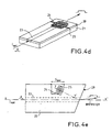
- FIGS. 4d and 4e show exemplary embodiments of acousto-optical device according to the techniques of integrated optics.
- a layer 20 of material having acoustic wave propagation properties (LiNBO 3 ) is formed an optical guide 23.
- interdigitated electrodes 24,25 the layer 20 is also piezoelectric in this case). case).
- a face 29 of the device is inclined by relative to the axis of the electrodes 24, 25 to reflect the acoustic wave collinearly to the axis of the optical guide 23.
- the invention is applied to the amplification of light pulses for the generation of ultrashort light pulses.
- obtaining an impulse ultra-short light of high peak power collides with the limits of the optical amplifier.
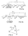
- the invention therefore provides for the application of the the invention in a chain of the type of Figure 5a.
- This chain includes an oscillator providing ultra-short pulses that are extended by the EXP expander.
- the extended impulses are then amplified by one or more passes in laser amplifiers (AMP) pumped by flash or by diodes.
- AMP laser amplifiers
- the generation of ultra-short pulses is then performed by conventional means of compression COMP from pairs of dispersive networks for example.
- the interest of the invention lies in the possibility of programming the extension of the pulse by the expansion device to be able to compensate for the effects of dispersions due to amplifying media and defects in network dispersions compression. According to the invention, provision is therefore made to make the operation of the extension device to program the extension different frequencies contained in the light pulses.
- An embodiment of the invention consists in providing in the source amplification system an acousto-optical programmable device as previously described, as shown in FIG. 5a, a acousto-optic device 1 is associated with a conventional extension device EXP of the dispersive network type.
- An optical oscillator OSC thus provides short-duration optical pulses I opt, for example 20 fs, to an acousto-optical device 1 which is a device of the type described above.
- the optical pulse supplied by the device 1 is transmitted to an extension device.
- EXP which transforms the pulse I opt into a signal of longer duration but of lower intensity.
- This signal is amplified by an AMP amplifier and the amplified optical signal is compressed to give a pulse of short duration and large amplitude.
- the device of the invention makes it possible to correct all the dispersion defects due respectively to the extension device, the amplifiers and the compression device. This is done by programming the acousto-optical device as previously described.
- FIGS. 5a and 5b it is also provided an adaptive loop between the output of the amplifier chain and the modulation control of the accusto-optical device 1.
- This loop makes it possible to measure the output pulse and to act by a processing circuit CT, using a convergence algorithm, on the control of modulation (on the control circuit 8 of Figure 4a).
- FIG. 5b it can be provided in certain cases of application to provide for the extension of pulses only the acousto-optical device 1 and do not provide a conventional extension device.
- FIG. 6 Another laser architecture incorporating a device programmable is shown in Figure 6.
- the acousto-optical device serves to compensate for the effects of dispersion due to the amplifying medium, optical components and mirrors constituting the laser cavity.
Abstract
Description
L'invention concerne un dispositif de contrôle d'impulsions lumineuses par un dispositif programmable acousto-optique et son application à des dispositifs de traitement d'impulsion et notamment à une source laser à impulsions ultra-courtes.The invention relates to a pulse control device by an acousto-optical programmable device and its application to impulse processing devices and in particular to a laser source with ultra-short pulses.
On connaít dans la technique des dispositifs mettant en oeuvre l'intéraction de dispositifs acoustiques sur le comportement de signaux optiques.It is known in the art devices implementing the interaction of acoustic devices on the behavior of signals optics.
Si on considère un milieu acoustique et notamment un milieu
élasto-optique anisotrope dans lequel on introduit une onde acoustique qui a
pour effet d'induire des variations d'indices optiques dans ce milieu et si on
introduit dans ce milieu une onde optique colinéaire à la direction de
propagation de l'onde acoustique, on a, une intéraction entre l'onde
acoustique et l'onde optique. Cette intéraction est due aux variations
d'indices sur l'onde optique. Si l'onde optique et l'onde acoustique sont
colinéaires, on a un couplage d'une onde optique diffractée κd à une onde
optique incidente κi par une onde acoustique κac comme cela est
représenté en figure 1 et on a : κ
Cette interaction acousto-optique couple l'onde incidente optique de nombre d'onde β1, à l'onde diffractée optique de nombre d'onde β2 par l'intermédiaire d'une onde acoustique de nombre d'ondes K dans un matériau élasto-optique anisotropeThis acousto-optical interaction couples the optical incident wave of wave number β 1 , to the optical diffracted wave of wave number β 2 by means of an acoustic wave of number of waves K in a material anisotropic elasto-optics
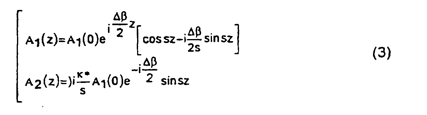
Posant

Les solutions des équations (2) s'écrivent pour A2(0) = 0 :
- ω étant la pulsion optique,
- c la vitesse de la lumière dans le vide,
- n1 et n2 les indices optiques associés respectivement à l'onde incidente et à l'onde diffractée,
- p la constante élasto-optique,
- S la contrainte acoustique,
- κ la constante de couplage,
- ρ la masse spécifique du matériau,
- v la vitesse acoustique et Iac l'intensité acoustique.
- ω being the optical drive,
- c the speed of light in a vacuum,
- n 1 and n 2 the optical indices associated respectively with the incident wave and the diffracted wave,
- p the elasto-optical constant,
- S the acoustic stress,
- κ the coupling constant,
- ρ the specific mass of the material,
- v the acoustic velocity and I ac the acoustic intensity.
A une distance Z la fraction d'énergie transférée de A1 vers A2
est :
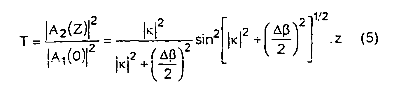
La totalité de l'énergie de l'onde incidente est transférée sur une
onde diffractée à une distance Lc, appelée longueur de couplage, lorsque :

Si l'onde optique incidente porte un signal si (t) et l'onde
acoustique de couplage un signal a (t), l'onde optique diffractée dans une
interaction colinéaire portera le signal de la forme :
Le signal sd (t) est le résultat du filtrage de si (t) par un filtrage de réponse impulsionnelle a (t).The signal s d (t) is the result of filtering s i (t) by impulse response filtering a (t).
En particulier, si le signal si (t) est une impulsion optique très
courte et le signal a (t) une impulsion acoustique longue modulée en
amplitude ou en fréquence de produit BT (bande passante × durée), le
signal sd (t) sera une impulsion optique longue modulée en amplitude ou en
fréquence de même produit BT recopiant fidèlement le code de l'onde
acoustique tel que Δβ = 0 :
- foρt étant la fréquence optique,
- fac la fréquence acoustique,
- Boρt la bande passante optique
- et Bac la bande acoustique.
- f oρt being the optical frequency,
- f ac the acoustic frequency,
- B o the optical bandwidth
- and B ac the acoustic band.
Dans les montages d'amplification d'impulsions lumineuses modulées en fréquence appelés CPA (Chirp Pulse Amplification), le problème consiste à générer à partir d'une impulsion optique très courte un signal optique long modulé en fréquence qui sera recomprimé après l'amplification laser.In the setups of amplification of light pulses frequency modulated termed CPA (Chirp Pulse Amplification), the problem is to generate from a very short optical pulse a long frequency modulated optical signal which will be recompressed after laser amplification.
Le dispositif de compression soumis à des puissances crêtes élevées, ne peut pas être programmable. Il est donc souhaitable que le dispositif d'extension qui opère à signal optique faible soit rendu programmable en fonction des défauts et des instabilités de la chaíne d'amplification laser.The compression device subjected to peak powers high, can not be programmable. It is therefore desirable that the extension device that operates at low optical signal is rendered programmable according to the faults and instabilities of the chain laser amplification.
En effet, lorsque le dispositif d'extension est parfaitement adapté au dispositif de compression en l'absence de chaíne d'amplification laser, le signal recomprimé est quasi-identique au signal optique très court de départ avant l'extension. Mais en présence de la chaíne d'amplification qui déforme les signaux, le signal recomprimé n'est pas identique au signal initial même lorsque l'extenseur et le compresseur sont parfaitement adaptés.Indeed, when the extension device is perfectly adapted to the compression device in the absence of a laser amplification chain, the recompressed signal is almost identical to the very short optical signal of departure before the extension. But in the presence of the amplification chain that distorts signals, the recompressed signal is not identical to the initial signal itself when the expander and the compressor are perfectly adapted.
Le seul moyen de compenser les défauts de l'amplification et de la compression est de disposer d'un filtre d'extension programmable.The only way to compensate for the defects of amplification and compression is to have a programmable extension filter.
Il est connu du document US-A-3 862 413 un dispositif acousto-optique programmable comprenant un milieu élasto-optique muni d'un transducteur acoustique capable de générer une onde acoustique dans le milieu élasto-optique, des moyens de couplage d'une impulsion optique d'entrée polarisée, un circuit de programmation de la modulation en fréquence ou en phase de l'onde acoustique et qui fournit une impulsion optique qui est la convolution de cette impulsion d'entrée avec le signal acoustique.It is known from US-A-3 862 413 an acousto-optical device programmable circuit comprising an elasto-optical medium provided with a acoustic transducer capable of generating an acoustic wave in the elasto-optical medium, means for coupling an optical pulse polarized input, a programming circuit of the modulation in frequency or phase of the acoustic wave and that provides a pulse optic which is the convolution of this input impulse with the signal acoustic.
L'invention propose d'utiliser ce type de dispositif acousto-optique dans un système d'amplification pour effectuer une compensation active des distorsions.The invention proposes to use this type of acousto-optical device in an amplification system to perform active compensation of distortions.
Plus précisément, l'invention concerne une source laser comportant un dispositif acousto-optique, comprenant un milieu élasto-optique muni d'un transducteur acoustique capable de générer dans le milieu élasto-optique une onde acoustique modulée selon une direction déterminée, ainsi que des moyens de couplage d'une onde optique incidente polarisée dans le milieu élasto-optique et comportant un circuit de programmation de la modulation en fréquences ou en phase de l'onde acoustique, ledit dispositif acousto-optique fournissant une impulsion optique qui est la convolution de cette impulsion d'entrée avec le signal acoustique, ledit dispositif acousto-optique recevant une impulsion optique incidente polarisée à amplifier et fournissant une impulsion optique étendue ; ladite source comportant en outre un amplificateur optique amplifiant l'impulsion optique étendue ainsi qu'un dispositif de compression optique effectuant une compression de l'impulsion optique étendue puis amplifiée, caractérisée en ce que la modulation de l'onde acoustique est programmée de façon à compenser les distorsions de la chaíne d'amplification.More specifically, the invention relates to a laser source comprising an acousto-optical device, comprising an elasto-optical medium equipped with an acoustic transducer capable of generating in the elasto-optical medium an acoustic wave modulated according to a direction determined, as well as means for coupling an incident optical wave polarized in the elasto-optical medium and comprising a circuit of programming the modulation in frequencies or phase of the wave acoustic, said acousto-optical device providing an optical pulse which is the convolution of this input pulse with the acoustic signal, said acousto-optical device receiving an incident optical pulse polarized to be amplified and providing an extended optical pulse; said source further comprising an optical amplifier amplifying the pulse extended optics as well as an optical compression device performing a compression of the extended optical pulse then amplified, characterized in that the modulation of the acoustic wave is programmed so as to compensate for the distortions of the amplification chain.
L'invention est applicable à une source laser délivrant des impulsions ultra-courtes. En effet, l'amplification d'une impulsion lumineuse se heurte aux limitations du milieu amplificateur.The invention is applicable to a laser source delivering ultra-short pulses. Indeed, the amplification of a light pulse faces the limitations of the amplifying medium.
Les différents objets et caractéristiques de l'invention apparaítront plus clairement dans la description qui va suivre et dans les figures annexées qui représentent :
- la figure 1, un diagramme des ondes-optique et acoustique qui interfèrent dans le milieu acoustique ;
- les figures 2a à 2c, un exemple de réalisation d'un dispositif acousto-optique utilisé dans l'invention;
- les figures 3a et 3b, des exemples de signaux optiques étendues;
- les figures 4a à 4e, des exemples de réalisation d'un dispositif d'expansion acousto-optique;
- les figures 5a et 5b, des exemples d'application de l'invention à des architectures lasers générant une impulsion ultra-courte ;
- la figure 6, un exemple d'oscillateur à cavité.
- FIG. 1, an optical-acoustic wave diagram that interferes with the acoustic medium;
- FIGS. 2a to 2c, an exemplary embodiment of an acousto-optical device used in the invention;
- FIGS. 3a and 3b, examples of extended optical signals;
- FIGS. 4a to 4e, exemplary embodiments of an acousto-optical expansion device;
- FIGS. 5a and 5b, examples of application of the invention to laser architectures generating an ultra-short pulse;
- FIG. 6, an example of a cavity oscillator.
Le dispositif de l'invention comporte une cellule élasto-optique 1 comportant une électrode ou un transducteur piézoélectrique 2 auquel est appliqué un signal électrique 3 induisant une onde acoustique a(t) dans le transducteur 1. Ce signal est modulé en fréquences par une succession de fréquences de modulation ou par une modulation variant continûment en fréquences. Un tel signal est représenté en figure 2a.The device of the invention comprises an elasto-optical cell 1 having an electrode or a piezoelectric transducer 2 to which is applied an electrical signal 3 inducing an acoustic wave a (t) in the transducer 1. This signal is frequency-modulated by a succession of modulation frequencies or by continuously varying modulation in frequencies. Such a signal is represented in FIG. 2a.
Une onde acoustique a(t) présentant les mêmes modulations en fréquences se propage donc dans le transducteur et induit des variations d'indices constituant différents réseaux (R1, R2, R3, ..., Rn) dont les pas correspondent aux fréquences de modulation. C'est ainsi que sur la figure 2b, le réseau R1 correspond à une fréquence de modulation f1, le réseau R2 correspond à une fréquence de modulation f2, le réseau R3 correspond à une fréquence de modulation f3, etc...An acoustic wave a (t) having the same modulations in frequencies therefore propagates in the transducer and induces variations of indices constituting different networks (R1, R2, R3, ..., Rn) whose steps correspond to the modulation frequencies. This is how in the figure 2b, the network R1 corresponds to a modulation frequency f1, the network R2 corresponds to a modulation frequency f2, the network R3 corresponds to a modulation frequency f3, etc.
Le transducteur reçoit par ailleurs une onde optique polarisée linéairement se présentant sous la forme d'une impulsion de courte durée et comportant différentes fréquences. Des moyens de couplage de l'onde optique dans le milieu élasto-optique seront décrit ultérieurement.The transducer also receives a polarized optical wave linearly in the form of a short pulse and with different frequencies. Means for coupling the wave in the elasto-optic medium will be described later.
Le milieu élasto-optique est un matériau birefringent. The elasto-optical medium is a birefringent material.
Les fréquences de modulation de l'onde optique sont telles que chaque fréquence de l'impulsion lumineuse diffracte sur un réseau (R1, R2, R3, ..., Rn) ou sur une partie de réseau.The modulation frequencies of the optical wave are such that each frequency of the diffracted light pulse on a network (R1, R2, R3, ..., Rn) or on a part of the network.
Cette diffraction a pour effet de réaliser une conversion de mode de polarisation de l'onde lumineuse. Par exemple, une onde polarisée TM est convertie en onde TE.This diffraction has the effect of achieving a fashion conversion of polarization of the light wave. For example, a polarized TM wave is converted to a TE wave.
Le matériau du milieu élasto-optique 1 étant birefringent et l'impulsion lumineuse étant polarisée TM (par exemple), à la fréquence f1 la polarisation TM de l'impulsion est convertie en polarisation TE par le premier réseau R1 ; à la fréquence f2, la polarisation TM est convertie en TE par le réseau R2 et ainsi de suite.The material of the elasto-optical medium 1 being birefringent and the light pulse being polarized TM (for example), at the frequency f1 the TM polarization of the pulse is converted into TE polarization by the first network R1; at the frequency f2, the polarization TM is converted into TE by the R2 network and so on.
La cellule est orientée de telle manière que l'impulsion lumineuse incidente a sa polarisation TM orientée suivant un axe z pour lequel l'indice optique est l'indice extraordinaire ne du milieu acousto-optique. Chaque onde optique diffractée est polarisée suivant un axe pour lequel l'indice optique est l'indice ordinaire no. Comme on le sait les vitesses de propagation des ondes sont différentes aux indices ne et no.The cell is oriented such that the incident light pulse has its polarization TM oriented along an axis z for which the optical index is the extraordinary index ne of the acousto-optical medium. Each diffracted optical wave is polarized along an axis for which the optical index is the ordinary index n o . As we know, the propagation velocities of the waves are different to the indices n e and n o .
Si on considère différentes fréquences de l'impulsion optique f1, f2, ..., fn :
- à la fréquence f1, l'onde subit une conversion de polarisation dès le réseau R1 et parcourt la longueur du transducteur à la vitesse vo correspondant à l'indice no.
- etc,
- à la fréquence fn, l'onde parcourt le transducteur à la vitesse ve, excepté le réseau Rn, par lequel est diffractée.
- at frequency f1, the wave undergoes polarization conversion from the network R1 and transducer traverses the length of the speed v o corresponding to the index n o.
- etc,
- at the frequency f n , the wave travels the transducer at the speed v e , except the grating R n , by which is diffracted.
On voit donc que les différentes fréquences de l'onde optique parcourent la longueur du transducteur à des vitesses moyennes différentes.So we see that the different frequencies of the optical wave traverse the length of the transducer at different average speeds.
En sortie du transducteur les différentes ondes lumineuses aux différentes fréquences sont réparties dans le temps.At the output of the transducer the different light waves at different frequencies are distributed over time.
L'impulsion lumineuse est donc étalée dans le temps. L'énergie d'une impulsion de courte durée est répartie dans une impulsion optique de longue durée.The light pulse is spread over time. energy a pulse of short duration is distributed in an optical pulse of long duration.
Le signal 3 appliqué à l'électrode du transducteur piézoélectrique est un signal électrique modulé en fréquences avec variation dans le temps de la fréquence de modulation. Le signal est fourni par un circuit de modulation 5 commandé par un signal de commande de modulation Cm (circuit 6) qui définit la loi de modulation. Par exemple, le signal Cm peut être un signal de variation linéaire et commande une variation linéaire dans le temps de la fréquence de modulation. Les différents réseaux R1 et Rn varieront alors continûment.The signal 3 applied to the electrode of the piezoelectric transducer is a frequency modulated electrical signal with variation over time the modulation frequency. The signal is provided by a circuit of modulation controlled by a modulation control signal Cm (circuit 6) which defines the modulation law. For example, the signal Cm can be a linear variation signal and control a linear variation in the time of the modulation frequency. The different networks R1 and Rn will then vary continuously.
Selon l'invention, il est important de commander à volonté la forme du signal de commande Cm. Cela permet de programmer la variation dans le temps de la fréquence de modulation. On aura alors des réseaux de longueurs différentes et on pourra avoir une impulsion optique étendue de sortie d'une forme adaptée du type par exemple de celui de la figure 3a. Egalement, on pourra avoir une impulsion étendue dont la répartition des fréquences est choisie en fonction de la programmation (voir en figure 3b par exemple).According to the invention, it is important to control at will the form of the control signal Cm. This allows programming the variation in the time of the modulation frequency. We will then have networks of different lengths and we can have an extended optical pulse of output of a suitable form of the type for example that of Figure 3a. Also, we can have an extended impulse whose distribution of frequencies is chosen according to the programming (see Figure 3b for example).
Le dispositif acousto-optique décrit permet donc d'étendre de façon programmable une impulsion lumineuse.The acousto-optical device described thus makes it possible to extend programmable way a light pulse.
Comme symbolisé en figure 2c, le milieu acousto-optique reçoit
une onde optique d'entrée (ωi, ki) et interfère avec un réseau d'indice créé
par une onde acoustique (Ω, Kac). On considère donc que l'onde optique
interfère avec l'onde acoustique. Une composante spectrale du signal de
sortie est de la forme :
Il s'ensuit que le signal de sortie est la convolution :
Dans ce qui précède on a considéré que l'onde acoustique et l'onde optique d'entrée sont colinéaires dans le milieu acousto-optique. Cependant, ces ondes pourraient ne pas être colinéaires. Les formules qui précédent seraient valables en considérant des formules vectorielles.In what precedes it was considered that the acoustic wave and the input optical wave are collinear in the acousto-optic medium. However, these waves may not be collinear. The formulas that precedent would be valid when considering vector formulas.
La figure 4a représente un exemple de réalisation d'un dispositif selon l'invention dans lequel les ondes optique et acoustique ne sont pas colinéaires.FIG. 4a represents an exemplary embodiment of a device according to the invention in which the optical and acoustic waves are not collinear.
Le transducteur acousto-optique est par exemple, du type décrit dans le document Acousto-Optic Tunable Filters de I.C. CHANG pubblié dans ACOUSTO-OPTIC SIGNAL PROCESSING pages 147-148 par NORMAN J. BERG - Maryland. Il possède un transducteur acousto-optique 1 possédant un transducteur piézoélectrique 2 permettant d'induire un réseau d'indice. Le transducteur accusto-optique 1 est par exemple un cristal TeO2 et est orienté comme indiqué en figure 4a. La direction de propagation de l'onde optique est convenablement orientée par rapport à l'onde acoustique pour qu'il y ait interaction avec le réseau d'indice. La face d'entrée 18 est inclinée convenablement pour l'entrée de l'onde optique.The acousto-optical transducer is, for example, of the type described in the Acousto-Optic Tunable Filters of IC CHANG published in ACOUSTO-OPTIC SIGNAL PROCESSING pages 147-148 by NORMAN J. BERG-Maryland. It has an acousto-optical transducer 1 having a piezoelectric transducer 2 for inducing an index grating. The accusto-optical transducer 1 is for example a TeO 2 crystal and is oriented as shown in FIG. 4a. The propagation direction of the optical wave is suitably oriented with respect to the acoustic wave for interaction with the index grating. The input face 18 is inclined appropriately for the input of the optical wave.
On va maintenant décrire des exemples de dispositifs acousto-optiques dans lesquels on prévoit que les ondes optique et acoustique sont colinéaires ou quasi-colinéaires.Examples of acousto-optical devices will now be described in which optical and acoustic waves are expected to be collinear or almost collinear.
Le matériau utilisé pour le transducteur acousto-optique est un matériau uniaxe tel que le LiNbO3 ou le CaMoO4, ou même le TeO2. A titre d'exemple, prenons comme matériau le niobate de lithium LiNbO3, comme axe de propagation l'axe y du niobate de lithium, l'axe C étant porté par l'axe z. Couplons une onde acoustique transversale de vitesse = v = 4.000m/sec polarisée suivant l'axe x du niobate de lithium à une onde optique incidente polarisée suivante l'axe z (ou c), pour laquelle l'indice optique est l'indice extraordinaire n1 = ne = 2,20. Dans ces conditions, l'onde optique diffractée sera une onde polarisée suivant l'axe x pour laquelle l'indice optique est l'indice ordinaire n2 = no = 2,29.The material used for the acousto-optical transducer is a uniaxial material such as LiNbO 3 or CaMoO 4 , or even TeO 2 . By way of example, lithium niobate LiNbO 3 is used as the axis of propagation for the y-axis of lithium niobate, the axis C being carried by the z axis. Coupling a velocity transverse acoustic wave = v = 4.000m / sec polarized along the x-axis of lithium niobate to an incident optical wave polarized along the z (or c) axis, for which the optical index is the index extraordinary n 1 = n e = 2.20. Under these conditions, the diffracted optical wave will be a polarized wave along the x axis for which the optical index is the ordinary index n 2 = n o = 2.29.
Pour une longueur d'onde optique dans le vide de λ0 = 0,8µ soit
une fréquence optique f0 = 375 THz, la fréquence de l'onde acoustique
transversale devra donc être :
Si l'impulsion optique courte a une durée de 20 fsec et couvre une
bande passante de Boρt = 0,5.1014Hz, la bande passante acoustique devra
être de :
Pour étendre 1.000 fois cette impulsion courte pour la porter à 20
psec, la durée Tac de l'impulsion acoustique devra être de :
Lorsqu'une impulsion longue de durée T est modulée linéairement
en fréquence dans une bande B, une fréquence particulière du spectre B
occupe une durée Tf:
Pour que la conversion de l'onde optique incidente vers l'onde
optique diffractée soit totale (100% de rendement de conversion), il faut que
la longueur de couplage Lo soit égale à la longueur occupée dans le cristal
par une fréquence particulière -fac de la bande Bac soit :
Posant, comme habituellement,
Dans le cas particulier du niobate de lithium de notre exemple :
En se reportant aux figures 4a à 4d, on va maintenant décrire différents exemples de réalisation de dispositifs acousto-optiques.Referring to Figures 4a to 4d, we will now describe different embodiments of acousto-optical devices.
Le dispositif de la figure 4b comporte un cristal 1 qui comprend une partie 13 prévue pour la propagation de l'onde optique. Une partie 10 inclinée par rapport à la partie 13 permet la génération d'une onde acoustique dans le dispositif à l'aide d'un dispositif piézoélectrique 2 commandé par les circuits 5 et 6. L'onde acoustique générée est réfléchie par une face inclinée 11 vers la partie 13 selon la direction de propagation de l'onde optique. L'onde optique incidente Si est couplée dans le milieu 13 par une face 12 selon une direction convenablement choisie du cristal 1.The device of Figure 4b comprises a crystal 1 which comprises a portion 13 provided for the propagation of the optical wave. An inclined portion relative to the portion 13 allows the generation of an acoustic wave in the device using a piezoelectric device 2 controlled by the circuits 5 and 6. The acoustic wave generated is reflected by an inclined face 11 to the part 13 according to the direction of propagation of the optical wave. The incident optical wave S i is coupled in the medium 13 by a face 12 in a suitably selected direction of the crystal 1.
Par exemple, comme décrit précédemment, dans le cas du LiNbO3 cette direction est colinéaire avec l'axe y du cristal. L'inclinaison de la face 11 est choisie de façon que la sortie de l'onde optique diffractée Sd se fasse sous incidence de Brewster.For example, as previously described, in the case of LiNbO 3 this direction is collinear with the y axis of the crystal. The inclination of the face 11 is chosen so that the output of the diffracted optical wave Sd is at the incidence of Brewster.
L'onde acoustique est générée dans le milieu élasto-optique par un transducteur acoustique 2 commandé, comme on l'a vu précédemment par un modulateur 5 commandé par un circuit programmable 6. The acoustic wave is generated in the elasto-optical medium by an acoustic transducer 2 controlled, as we saw previously by a modulator 5 controlled by a programmable circuit 6.
De plus, il convient que l'émission de l'impulsion lumineuse incidente Si soit synchronisée, dans le milieu acoustique 13, avec l'onde acoustique. Pour cela, l'impulsion lumineuse Si est fournie par la source 7 dont l'émission est commandée par un circuit de synchronisation 8 qui commande également le fonctionnement du modulateur 5.In addition, it is appropriate that the emission of the incident light pulse Si is synchronized, in the acoustic medium 13, with the acoustic wave. For this, the light pulse S i is supplied by the source 7 whose transmission is controlled by a synchronization circuit 8 which also controls the operation of the modulator 5.
La figure 4c représente un dispositif dans lequel on a prévu, selon la direction de propagation de l'onde acoustique, des moyens pour réfléchir l'onde optique Si.FIG. 4c represents a device in which, in the direction of propagation of the acoustic wave, means are provided for reflecting the optical wave S i .
L'onde acoustique est générée dans la partie 13 du cristal selon un axe du cristal choisi précédemment. Selon cet axe, sont prévus des miroirs 15 et 16 qui permettent la propagation de l'onde acoustique et qui orientée selon un angle (à 45° par exemple) permettent l'entrée de l'onde optique incidente Si et la sortie de l'onde optique diffractée. Ces miroirs 15, 16 sont par exemple des couches en matériaux diélectriques optiques. Ils peuvent être réalisés sous forme de multi-couches (par exemple SiO/ZnO, SiO2/ZnO2) ou en couche mince d'ITO. Pour réaliser un tel dispositif on découpe en biais un élément 1 et on dépose la multi-couche diélectrique sur la face découpée de l'élément 13, puis on recolle les deux éléments découpés pour reconstituer l'élément 1. L'épaisseur des couches de réflexion 15, 16 doit être très petite par rapport à la longueur d'onde acoustique.The acoustic wave is generated in the portion 13 of the crystal along an axis of the crystal chosen above. According to this axis, there are provided mirrors 15 and 16 which allow the propagation of the acoustic wave and which is oriented at an angle (at 45 ° for example) allow the input of the incident optical wave S i and the output of the diffracted optical wave. These mirrors 15, 16 are for example layers of optical dielectric materials. They can be made in the form of multi-layers (for example S i O / Z n O, S i O 2 / Z n O 2 ) or in thin layer of ITO. In order to produce such a device, an element 1 is cut at an angle and the dielectric multi-layer is deposited on the cut face of the element 13, then the two cut elements are glued together to reconstitute the element 1. The thickness of the layers of reflection 15, 16 must be very small compared to the acoustic wavelength.
Les figures 4d, 4e représentent des exemples de réalisation du dispositif acousto-optique selon les techniques de l'optique intégrée.FIGS. 4d and 4e show exemplary embodiments of acousto-optical device according to the techniques of integrated optics.
Dans une couche 20 de matériau présentant des propriétés de propagation d'ondes acoustiques (LiNBO3) est réalisé un guide optique 23. A la surface de la couche 20 sont prévues des électrodes interdigittées 24,25 (la couche 20 est également piézoélectrique dans ce cas).In a layer 20 of material having acoustic wave propagation properties (LiNBO 3 ) is formed an optical guide 23. On the surface of the layer 20 are provided interdigitated electrodes 24,25 (the layer 20 is also piezoelectric in this case). case).
Selon la figure 4e, une face 29 du dispositif est inclinée par rapport à l'axe des électrodes 24, 25 pour réfléchir l'onde acoustique colinéairement à l'axe du guide optique 23.According to FIG. 4e, a face 29 of the device is inclined by relative to the axis of the electrodes 24, 25 to reflect the acoustic wave collinearly to the axis of the optical guide 23.
Dans ce qui précède, il est possible de prévoir, en sortie de l'onde acoustique, des moyens pour absorber l'onde acoustique (couches absorbantes).In the above, it is possible to predict, at the output of the wave acoustics, means for absorbing the acoustic wave (layers absorbent).
L'invention est appliquée à l'amplification d'impulsions lumineuses pour la génération d'impulsions lumineuses ultracourtes. Notamment, on veut contrôler la durée de l'impulsion. En effet, l'obtention d'une impulsion lumineuse ultra-courte de puissance crête élevée se heurte aux limites de l'amplificateur optique. L'invention prévoit donc l'application du dispositif de l'invention dans une chaíne du type de la figure 5a. Cette chaíne comporte un oscillateur fournissant des impulsions ultra-courtes qui sont étendues par le dispositif d'extension EXP. Les impulsions étendues sont ensuite amplifiées par un ou plusieurs passages dans des amplificateurs laser (AMP) pompés par flash ou par diodes. La génération d'impulsions ultra-courtes est ensuite réalisée par des moyens classiques de compression COMP à partir de paires de réseaux dispersifs par exemple. L'intérêt de l'invention tient à la possibilité de programmer l'extension de l'impulsion par le dispositif d'extension pour pouvoir compenser les effets de dispersions dus aux milieux amplificateurs et les défauts de dispersions de réseaux de compression. Selon l'invention, on prévoit donc de rendre programmable le fonctionnement du dispositif d'extension de façon à programmer l'extension des différentes fréquences contenues dans les impulsions lumineuses.The invention is applied to the amplification of light pulses for the generation of ultrashort light pulses. In particular, we wants to control the duration of the pulse. Indeed, obtaining an impulse ultra-short light of high peak power collides with the limits of the optical amplifier. The invention therefore provides for the application of the the invention in a chain of the type of Figure 5a. This chain includes an oscillator providing ultra-short pulses that are extended by the EXP expander. The extended impulses are then amplified by one or more passes in laser amplifiers (AMP) pumped by flash or by diodes. The generation of ultra-short pulses is then performed by conventional means of compression COMP from pairs of dispersive networks for example. The interest of the invention lies in the possibility of programming the extension of the pulse by the expansion device to be able to compensate for the effects of dispersions due to amplifying media and defects in network dispersions compression. According to the invention, provision is therefore made to make the operation of the extension device to program the extension different frequencies contained in the light pulses.
Une forme de réalisation de l'invention consiste à prévoir dans la chaíne d'amplification de la source un dispositif programmable acousto-optique tel que décrit précédemment, comme représenté en figure 5a, un dispositif acousto-optique 1 est associé à un dispositif d'extension classique EXP du type réseau dispersif.An embodiment of the invention consists in providing in the source amplification system an acousto-optical programmable device as previously described, as shown in FIG. 5a, a acousto-optic device 1 is associated with a conventional extension device EXP of the dispersive network type.
Un oscillateur optique OSC fournit donc des impulsions optiques Iopt de courtes durées par exemple 20 fs à un dispositif acousto-optique 1 qui est un dispositif du type décrit précédemment L'impulsion optique fournie par le dispositif 1 est transmise à un dispositif d'extension EXP qui transforme l'impulsion Iopt en un signal de durée plus longue mais d'intensité plus faible. Ce signal est amplifié par un amplificateur AMP et le signal optique amplifié est comprimé pour donner une impulsion de courte durée et de grande amplitude. Dans ce mode de fonctionnement, le dispositif de l'invention permet de corriger l'ensemble des défauts de dispersion dus respectivement au dispositif d'extension, aux amplificateurs et au dispositif de compression. Cela se fait par programmation du dispositif acousto-optique comme cela a été décrit précédemment.An optical oscillator OSC thus provides short-duration optical pulses I opt, for example 20 fs, to an acousto-optical device 1 which is a device of the type described above. The optical pulse supplied by the device 1 is transmitted to an extension device. EXP which transforms the pulse I opt into a signal of longer duration but of lower intensity. This signal is amplified by an AMP amplifier and the amplified optical signal is compressed to give a pulse of short duration and large amplitude. In this mode of operation, the device of the invention makes it possible to correct all the dispersion defects due respectively to the extension device, the amplifiers and the compression device. This is done by programming the acousto-optical device as previously described.
Comme représenté en figures 5a et 5b, il est également prévue une boucle adaptative entre la sortie de la chaíne d'amplification et la commande de modulation du dispositif accusto-optique 1. Cette boucle permet de mesurer l'impulsion de sortie et d'agir par un circuit de traitement CT, à l'aide d'un algorithme de convergence, sur la commande de modulation (sur le circuit de commande 8 de la figure 4a).As shown in FIGS. 5a and 5b, it is also provided an adaptive loop between the output of the amplifier chain and the modulation control of the accusto-optical device 1. This loop makes it possible to measure the output pulse and to act by a processing circuit CT, using a convergence algorithm, on the control of modulation (on the control circuit 8 of Figure 4a).
Selon la figure 5b, on peut prévoir dans certains cas d'application de ne prévoir pour l'extension des impulsions que le dispositif acousto-optique 1 et ne pas prévoir de dispositif d'extension classique.According to FIG. 5b, it can be provided in certain cases of application to provide for the extension of pulses only the acousto-optical device 1 and do not provide a conventional extension device.
Une autre architecture de laser intégrant un dispositif programmable est représentée en figure 6. A titre d'exemple, elle utilise une cavité dans laquelle le dispositif acousto-optique sert à compenser les effets de dispersion dus au milieu amplificateur, composants optiques et miroirs constituant la cavité du laser.Another laser architecture incorporating a device programmable is shown in Figure 6. For example, it uses a cavity in which the acousto-optical device serves to compensate for the effects of dispersion due to the amplifying medium, optical components and mirrors constituting the laser cavity.
On prévoit donc de placer dans la cavité un dispositif acousto-optique dont le signal acoustique est programmé pour compenser les distorsions. Notamment la modulation du signal acoustique est organisée en conséquence des distorsions en fréquences de tous les composants optiques de la cavité. Dans ces conditions une impulsion ultra-courte limitée temporellement par diffraction peut être obtenue sur le faisceau de sortie de cette architecture laser.It is therefore planned to place in the cavity a acousto-optical device whose acoustic signal is programmed to compensate for distortions. In particular the modulation of the acoustic signal is organized as a consequence of frequency distortions of all optical components of the cavity. Under these conditions an ultra-short pulse temporally limited by diffraction can be obtained on the output beam of this laser architecture.
Claims (14)
- Laser source comprising:characterized in that it further comprises:an optical pulse source (osc);an acoustooptic device, comprising:the said acoustooptic device being designed to deliver a temporally expanded optical pulse which is the convolution of the incident optical pulse with the acoustic signal;an elastooptic medium (1) provided with an acoustic transducer (2) capable of generating a modulated acoustic wave in the elastooptic medium along a defined direction;means for coupling a polarized incident optical pulse (Si) intended to be amplified in the elastooptic medium; anda circuit (6) for programming the frequency modulation or phase modulation of the acoustic wave,an optical amplifier (AMP) designed to amplify the expanded optical pulse;a compression device (COMP) designed to compress the expanded and amplified optical pulse; and in thatthe modulation of the acoustic wave is programmed so as to compensate for the distortions of the optical pulse that are introduced by the optical amplifier and the compression device.
- Laser source according to Claim 1, characterized in that the acoustic wave and the optical wave are collinear or almost collinear.
- Laser source according to Claim 1, characterized in that the acoustic wave and the optical wave are neither collinear nor almost collinear.
- Laser source according to Claim 1, characterized in that the circuit for programming the modulation of the acoustic wave makes it possible for a continuity of gratings of different spacings to be created in the elastooptic medium and for them to coexist therein.
- Laser source according to Claim 1, characterized in that it comprises an expansion device (EXP) located between the acoustooptic device (1) and the amplifier (AMP) or upstream of the acoustooptic device (1).
- Laser source according to Claim 1, characterized in that it includes a modulation circuit (5) and an adaptive loop circuit (CC) which measures the optical pulses delivered by the optical compression device (COMP) at the output of the amplification chain and acts on the modulation circuit (5).
- Laser source according to Claim 1, characterized in that the acoustic wave and the incident optical wave (Si) are collinear and directed along an axis of the elastooptic medium in which an index grating created by the acoustic wave brings about, for certain frequencies, a conversion (TE, TM) of the mode of polarization of the incident optical wave.
- Laser source according to Claim 1, characterized in that the acoustooptic device includes a modulation circuit (5) controlling the modulation of the acoustic wave under the control of the programming circuit (6), and a synchronization circuit (8) which synchronizes the operation of the optical pulse source (osc) and the modulation circuit (5).
- Laser source according to Claim 1, characterized in that the elastooptic medium includes a first part (13) for the collinear propagation of the incident optical wave (Si) and of the acoustic wave and a second part making an angle with the first part, the junction between the two parts having a face for reflecting the acoustic wave from the second part to the first part.
- Laser source according to Claim 9, characterized in that the said face makes an angle with the direction of propagation of the optical wave in the elastooptic medium such that the diffracted optical wave can exit the medium at Brewster incidence.
- Laser source according to Claim 1, characterized in that the elastooptic medium includes, along the direction of propagation of the acoustic wave, at least one optical mirror (15) making an angle with this direction, receiving the incident optical wave (Si) and allowing the incident optical wave to be collinearly coupled with the acoustic wave in the elastooptic medium.
- Laser source according to Claim 1, characterized in that the acoustooptic device includes:a waveguide formed in a layer of a crystalline material (20) having acoustooptic properties, this layer being formed on a substrate (21);means for inducing an acoustic wave in the said layer collinearly with the optical guide.
- Laser source according to Claim 12, characterized in that the means for inducing an acoustic wave include interdigitated electrodes located above the optical guide.
- Laser source according to Claim 13, characterized in that the means for inducing an acoustic wave include a face (29) of the layer of crystalline material (20), this face being inclined with respect to the axis of the optical guide, and interdigitated electrodes (24, 25) making it possible to induce an acoustic wave in the layer (20) towards said face (29) which reflects the acoustic wave collinearly with respect to the guide.
Applications Claiming Priority (5)
| Application Number | Priority Date | Filing Date | Title |
|---|---|---|---|
| FR9608510 | 1996-07-09 | ||
| FR9608510A FR2751094A1 (en) | 1996-07-09 | 1996-07-09 | Acousto-optical device for programming sequence of light pulses of laser |
| FR9610717A FR2751095B1 (en) | 1996-07-09 | 1996-09-03 | DEVICE FOR CONTROLLING LIGHT PULSES BY AN ACOUSTO-OPTIC PROGRAMMABLE DEVICE |
| FR9610717 | 1996-09-03 | ||
| PCT/FR1997/001206 WO1998001788A1 (en) | 1996-07-09 | 1997-07-04 | Device for controlling light impulses by a programmable acousto-optic means |
Publications (2)
| Publication Number | Publication Date |
|---|---|
| EP0882251A1 EP0882251A1 (en) | 1998-12-09 |
| EP0882251B1 true EP0882251B1 (en) | 2005-12-07 |
Family
ID=26232820
Family Applications (1)
| Application Number | Title | Priority Date | Filing Date |
|---|---|---|---|
| EP97931873A Expired - Lifetime EP0882251B1 (en) | 1996-07-09 | 1997-07-04 | Device for controlling light pulses by a programmable acousto-optic means |
Country Status (6)
| Country | Link |
|---|---|
| US (1) | US6072813A (en) |
| EP (1) | EP0882251B1 (en) |
| AT (1) | ATE312370T1 (en) |
| DE (1) | DE69734821T2 (en) |
| FR (1) | FR2751095B1 (en) |
| WO (1) | WO1998001788A1 (en) |
Families Citing this family (34)
| Publication number | Priority date | Publication date | Assignee | Title |
|---|---|---|---|---|
| FR2810750B1 (en) * | 2000-06-21 | 2002-09-06 | Fastlite | PROGRAMMABLE ACOUSTO-OPTICAL DEVICE FOR CONTROLLING THE AMPLITUDE OF SPECTRUM IN WAVELENGTHS OF WAVELENGTH MULTIPLEX OPTICAL COMMUNICATION SYSTEMS |
| US6510256B1 (en) * | 2000-06-29 | 2003-01-21 | Proximion Fiber Optics Ab | Method and arrangement in connection with optical bragg-reflectors |
| US8208505B2 (en) * | 2001-01-30 | 2012-06-26 | Board Of Trustees Of Michigan State University | Laser system employing harmonic generation |
| US7567596B2 (en) * | 2001-01-30 | 2009-07-28 | Board Of Trustees Of Michigan State University | Control system and apparatus for use with ultra-fast laser |
| US7450618B2 (en) | 2001-01-30 | 2008-11-11 | Board Of Trustees Operating Michigan State University | Laser system using ultrashort laser pulses |
| US7583710B2 (en) * | 2001-01-30 | 2009-09-01 | Board Of Trustees Operating Michigan State University | Laser and environmental monitoring system |
| US7609731B2 (en) * | 2001-01-30 | 2009-10-27 | Board Of Trustees Operating Michigan State University | Laser system using ultra-short laser pulses |
| AU2002245345A1 (en) | 2001-01-30 | 2002-08-12 | Board Of Trustees Operating Michigan State University | Control system and apparatus for use with laser excitation or ionization |
| US7973936B2 (en) * | 2001-01-30 | 2011-07-05 | Board Of Trustees Of Michigan State University | Control system and apparatus for use with ultra-fast laser |
| FR2820837B1 (en) * | 2001-02-12 | 2003-05-16 | Fastlite | IMPROVEMENT ON PROGRAMMABLE ACOUSTO-OPTICAL DEVICES FOR OPTICAL COMMUNICATION SYSTEMS |
| FR2827679B1 (en) * | 2001-07-20 | 2003-11-14 | Thales Sa | COMPACT AND ADAPTIVE ULTRA-SHORT PULSE DRAWER |
| US6490075B1 (en) * | 2001-08-16 | 2002-12-03 | The United States Of America As Represented By The Secretary Of The Navy | Acousto-optic tunable filter hyperspectral imaging system |
| FR2834080B1 (en) * | 2001-12-20 | 2004-04-30 | Thales Sa | AMPLIFIER CHAIN FOR THE GENERATION OF HIGH POWER ULTRA-SHORT PULSES |
| KR100443288B1 (en) * | 2002-01-22 | 2004-08-09 | 한국전자통신연구원 | Optical oscillator with milimeterwave frequency |
| WO2003096495A1 (en) * | 2002-05-10 | 2003-11-20 | The Regents Of The University Of Colorado | Pulse amplification with stretcher providing negative dispersion |
| FR2852155B1 (en) * | 2003-03-03 | 2006-08-25 | Fastlite | METHOD AND DEVICE FOR CONTROLLING WAVELENGTH SPECTRUM AMPLITUDE OF ULTRA-BRIEF LUMINOUS PULSES ISSUED BY MULTI-PASSAGE LASER AMPLIFIERS |
| FR2872592B1 (en) | 2004-07-02 | 2006-09-15 | Thales Sa | AMPLIFIER CHAIN FOR THE GENERATION OF ULTRACOURTE LIGHT PULSES OF DIFFERENT PULSE STRESSES |
| WO2006088841A1 (en) * | 2005-02-14 | 2006-08-24 | Board Of Trustees Of Michigan State University | Ultra-fast laser system |
| FR2887327B1 (en) | 2005-06-17 | 2007-08-24 | Thales Sa | METHOD FOR THE PROTECTION OF ANTIMISSIL VEHICLES AND DEVICE FOR IMPLEMENTING THE SAME |
| US20060293644A1 (en) * | 2005-06-21 | 2006-12-28 | Donald Umstadter | System and methods for laser-generated ionizing radiation |
| WO2007064703A2 (en) | 2005-11-30 | 2007-06-07 | Board Of Trustees Of Michigan State University | Laser based identification of molecular characteristics |
| WO2007145702A2 (en) | 2006-04-10 | 2007-12-21 | Board Of Trustees Of Michigan State University | Laser material processing systems and methods with, in particular, use of a hollow waveguide for broadening the bandwidth of the pulse above 20 nm |
| WO2008094274A1 (en) * | 2006-04-28 | 2008-08-07 | Cornell Research Foundation, Inc . | Methods and systems for compensation of self-phase modulation in fiber-based amplification systems |
| DE102006034755A1 (en) * | 2006-07-24 | 2008-01-31 | Carl Zeiss Smt Ag | Optical device and method for correcting or improving the imaging behavior of an optical device |
| US8311069B2 (en) | 2007-12-21 | 2012-11-13 | Board Of Trustees Of Michigan State University | Direct ultrashort laser system |
| US8675699B2 (en) * | 2009-01-23 | 2014-03-18 | Board Of Trustees Of Michigan State University | Laser pulse synthesis system |
| US8861075B2 (en) | 2009-03-05 | 2014-10-14 | Board Of Trustees Of Michigan State University | Laser amplification system |
| US8630322B2 (en) * | 2010-03-01 | 2014-01-14 | Board Of Trustees Of Michigan State University | Laser system for output manipulation |
| DK2629142T3 (en) | 2012-02-14 | 2019-07-22 | Fastlite | Rapid optical delay scanning method and apparatus using time dependence of acousto-optic diffraction |
| CN103968989B (en) * | 2014-05-15 | 2017-02-01 | 黑龙江大学 | Method for measuring micro impulse by means of linear frequency modulation multi-beam laser heterodyne quadratic harmonic method and torsional pendulum method |
| CN103954392B (en) * | 2014-05-15 | 2016-04-13 | 黑龙江大学 | What micro-momentum device was rocked in the measurement of linear frequency modulation multi-beam laser heterodyne rocks micro-impulse measurement method |
| HUP1500264A2 (en) * | 2015-06-01 | 2018-05-02 | Femtonics Kft | Layered structured acousto-optical deflector and method for optical beam deflection with deflectior |
| DE102018132327B4 (en) * | 2018-12-14 | 2021-02-25 | Leica Microsystems Cms Gmbh | Method and signal generator for controlling an acousto-optical element as well as an arrangement and microscope with a signal generator |
| CN117471720B (en) * | 2023-12-27 | 2024-04-09 | 武汉中科锐择光电科技有限公司 | Ultra-short pulse shaping device based on acousto-optic delay line |
Citations (1)
| Publication number | Priority date | Publication date | Assignee | Title |
|---|---|---|---|---|
| US3862413A (en) * | 1972-12-15 | 1975-01-21 | United Aircraft Corp | Apparatus for providing pulses having electronically variable characteristics |
Family Cites Families (16)
| Publication number | Priority date | Publication date | Assignee | Title |
|---|---|---|---|---|
| FR1407688A (en) * | 1964-06-05 | 1965-08-06 | Csf | Interferometer for the compression of pulsed wave trains |
| FR1452050A (en) * | 1965-05-03 | 1966-02-25 | Csf | Dispersive acoustic lines |
| FR1482899A (en) * | 1966-03-17 | 1967-06-02 | Csf | Dispersive acoustic lines |
| FR1526082A (en) * | 1967-03-29 | 1968-05-24 | Csf | Dispersive delay line with tubular section |
| FR2068014A5 (en) * | 1969-11-25 | 1971-08-20 | Thomson Csf | |
| FR2151727A5 (en) * | 1971-09-10 | 1973-04-20 | Thomson Csf | |
| FR2250102B1 (en) * | 1973-10-31 | 1976-10-01 | Thomson Csf | |
| FR2266394B1 (en) * | 1974-03-26 | 1981-02-27 | Thomson Csf | |
| US4134623A (en) * | 1974-11-08 | 1979-01-16 | Thomson-Csf | System for processing an electric signal using elastic surface waves |
| US4159539A (en) * | 1974-11-08 | 1979-06-26 | Thomson-Csf | Elastic waves device for memorizing information |
| FR2365138A1 (en) * | 1976-09-17 | 1978-04-14 | Thomson Csf | CODING SYSTEM BY MODULATION OF A LIGHT SIGNAL |
| FR2478824A1 (en) * | 1980-03-21 | 1981-09-25 | Thomson Csf | ACOUSTIC IMAGING SYSTEM |
| US4344675A (en) * | 1980-05-29 | 1982-08-17 | Rockwell International Corporation | Optical signal processing device |
| US4540245A (en) * | 1983-11-10 | 1985-09-10 | Isomet Corporation | Apparatus and method for acousto-optic character generation |
| CA1276320C (en) * | 1987-12-01 | 1990-11-13 | John Allan Rowlands | System for measuring the charge distribution on a photoreceptor surface |
| US5499134A (en) * | 1994-08-24 | 1996-03-12 | Imra America | Optical pulse amplification using chirped Bragg gratings |
-
1996
- 1996-09-03 FR FR9610717A patent/FR2751095B1/en not_active Expired - Lifetime
-
1997
- 1997-07-04 WO PCT/FR1997/001206 patent/WO1998001788A1/en active IP Right Grant
- 1997-07-04 US US09/029,065 patent/US6072813A/en not_active Expired - Lifetime
- 1997-07-04 EP EP97931873A patent/EP0882251B1/en not_active Expired - Lifetime
- 1997-07-04 AT AT97931873T patent/ATE312370T1/en active
- 1997-07-04 DE DE69734821T patent/DE69734821T2/en not_active Expired - Lifetime
Patent Citations (1)
| Publication number | Priority date | Publication date | Assignee | Title |
|---|---|---|---|---|
| US3862413A (en) * | 1972-12-15 | 1975-01-21 | United Aircraft Corp | Apparatus for providing pulses having electronically variable characteristics |
Also Published As
| Publication number | Publication date |
|---|---|
| WO1998001788A1 (en) | 1998-01-15 |
| US6072813A (en) | 2000-06-06 |
| DE69734821T2 (en) | 2006-07-27 |
| FR2751095A1 (en) | 1998-01-16 |
| FR2751095B1 (en) | 1998-10-30 |
| DE69734821D1 (en) | 2006-01-12 |
| ATE312370T1 (en) | 2005-12-15 |
| EP0882251A1 (en) | 1998-12-09 |
Similar Documents
| Publication | Publication Date | Title |
|---|---|---|
| EP0882251B1 (en) | Device for controlling light pulses by a programmable acousto-optic means | |
| EP0472709B1 (en) | Device for producing optical delays and application to an optical control system of a sweep aerial | |
| EP1604435B1 (en) | Method and device for controlling the amplitude of the wavelength spectrum of ultra-short light pulses emitted by multipass laser amplifiers | |
| EP0603036B1 (en) | Optical processing apparatus for electrical signals | |
| FR2533714A1 (en) | NON-LINEAR INTEGRATED OPTICAL COUPLER DEVICE AND PARAMETRIC OSCILLATOR COMPRISING SUCH A DEVICE | |
| FR2810750A1 (en) | Programmable acousto-optic filter includes birefringent material in which optical signals couple with acoustic wave pattern | |
| EP1412814B1 (en) | Wide band electro-optical modulators | |
| EP1738444A1 (en) | Device for shifting frequency in an optical field with a pulsed laser source | |
| FR2647552A1 (en) | ELECTRIC SIGNAL MEASUREMENT SYSTEM USING ULTRA-SHORT OPTICAL PULSES | |
| EP0505235A1 (en) | Wide-band intercorrelation method and apparatus | |
| FR2749407A1 (en) | Optical frequency shifting device for submarine transmission cable | |
| FR2751094A1 (en) | Acousto-optical device for programming sequence of light pulses of laser | |
| EP0975106B1 (en) | Device for on-line regeneration of an optical soliton signal by synchronous modulation of these solitons and transmission system comprising such a device | |
| EP1185901B1 (en) | Method and device for programmable shaping of a time profile for quasi-monochromatic optical pulses | |
| EP0421880B1 (en) | Multipurpose integrated optics component and distribution network with optical amplification | |
| CA2142771A1 (en) | Polarization scrambler optical communication system | |
| EP0745232B1 (en) | Electro-optical modulator | |
| FR2686198A1 (en) | METHOD AND DEVICE FOR GENERATING IMPULSE TRANSMISSION USING A LASER SOURCE | |
| FR2632082A1 (en) | Acoustooptic modulator | |
| FR2820837A1 (en) | IMPROVEMENT ON PROGRAMMABLE ACOUSTO-OPTICAL DEVICES FOR OPTICAL COMMUNICATION SYSTEMS | |
| WO2002093118A2 (en) | Characterisation of low-power short pulses | |
| FR2827679A1 (en) | Ultrashort optical pulse amplifier, has index network inscribed in optical block formed by holographic inscription in photosensitive material | |
| FR2772938A1 (en) | Arbitrary waveform electrical signal generator | |
| FR2757647A1 (en) | ELECTROOPTIC MODULATOR OF LIGHT BEAM | |
| FR2860120A1 (en) | Light signal measuring process, involves analyzing short pulse train, and applying inverse relation of deterministic relation of temporal wave form of each pulse to samples for measuring temporal waveform of light signal |
Legal Events
| Date | Code | Title | Description |
|---|---|---|---|
| PUAI | Public reference made under article 153(3) epc to a published international application that has entered the european phase |
Free format text: ORIGINAL CODE: 0009012 |
|
| 17P | Request for examination filed |
Effective date: 19980226 |
|
| AK | Designated contracting states |
Kind code of ref document: A1 Designated state(s): AT DE FR GB IT |
|
| 17Q | First examination report despatched |
Effective date: 20041108 |
|
| RAP1 | Party data changed (applicant data changed or rights of an application transferred) |
Owner name: THALES |
|
| GRAP | Despatch of communication of intention to grant a patent |
Free format text: ORIGINAL CODE: EPIDOSNIGR1 |
|
| RTI1 | Title (correction) |
Free format text: DEVICE FOR CONTROLLING LIGHT PULSES BY A PROGRAMMABLE ACOUSTO-OPTIC MEANS |
|
| GRAS | Grant fee paid |
Free format text: ORIGINAL CODE: EPIDOSNIGR3 |
|
| GRAA | (expected) grant |
Free format text: ORIGINAL CODE: 0009210 |
|
| AK | Designated contracting states |
Kind code of ref document: B1 Designated state(s): AT DE FR GB IT |
|
| REG | Reference to a national code |
Ref country code: GB Ref legal event code: FG4D Free format text: NOT ENGLISH |
|
| REF | Corresponds to: |
Ref document number: 69734821 Country of ref document: DE Date of ref document: 20060112 Kind code of ref document: P |
|
| GBT | Gb: translation of ep patent filed (gb section 77(6)(a)/1977) |
Effective date: 20060213 |
|
| PLBE | No opposition filed within time limit |
Free format text: ORIGINAL CODE: 0009261 |
|
| STAA | Information on the status of an ep patent application or granted ep patent |
Free format text: STATUS: NO OPPOSITION FILED WITHIN TIME LIMIT |
|
| 26N | No opposition filed |
Effective date: 20060908 |
|
| REG | Reference to a national code |
Ref country code: FR Ref legal event code: PLFP Year of fee payment: 20 |
|
| PGFP | Annual fee paid to national office [announced via postgrant information from national office to epo] |
Ref country code: GB Payment date: 20160610 Year of fee payment: 20 |
|
| PGFP | Annual fee paid to national office [announced via postgrant information from national office to epo] |
Ref country code: FR Payment date: 20160628 Year of fee payment: 20 |
|
| PGFP | Annual fee paid to national office [announced via postgrant information from national office to epo] |
Ref country code: IT Payment date: 20160720 Year of fee payment: 20 Ref country code: DE Payment date: 20160628 Year of fee payment: 20 |
|
| PGFP | Annual fee paid to national office [announced via postgrant information from national office to epo] |
Ref country code: AT Payment date: 20160630 Year of fee payment: 20 |
|
| REG | Reference to a national code |
Ref country code: DE Ref legal event code: R071 Ref document number: 69734821 Country of ref document: DE |
|
| REG | Reference to a national code |
Ref country code: GB Ref legal event code: PE20 Expiry date: 20170703 |
|
| PG25 | Lapsed in a contracting state [announced via postgrant information from national office to epo] |
Ref country code: GB Free format text: LAPSE BECAUSE OF EXPIRATION OF PROTECTION Effective date: 20170703 |
|
| REG | Reference to a national code |
Ref country code: AT Ref legal event code: MK07 Ref document number: 312370 Country of ref document: AT Kind code of ref document: T Effective date: 20170704 |