EP0880871B1 - Tonaufnahme- und -wiedergabesysteme - Google Patents
Tonaufnahme- und -wiedergabesysteme Download PDFInfo
- Publication number
- EP0880871B1 EP0880871B1 EP97903466A EP97903466A EP0880871B1 EP 0880871 B1 EP0880871 B1 EP 0880871B1 EP 97903466 A EP97903466 A EP 97903466A EP 97903466 A EP97903466 A EP 97903466A EP 0880871 B1 EP0880871 B1 EP 0880871B1
- Authority
- EP
- European Patent Office
- Prior art keywords
- loudspeakers
- loudspeaker
- sound
- reproduction system
- listener
- Prior art date
- Legal status (The legal status is an assumption and is not a legal conclusion. Google has not performed a legal analysis and makes no representation as to the accuracy of the status listed.)
- Expired - Lifetime
Links
Images











Classifications
-
- H—ELECTRICITY
- H04—ELECTRIC COMMUNICATION TECHNIQUE
- H04R—LOUDSPEAKERS, MICROPHONES, GRAMOPHONE PICK-UPS OR LIKE ACOUSTIC ELECTROMECHANICAL TRANSDUCERS; ELECTRIC HEARING AIDS; PUBLIC ADDRESS SYSTEMS
- H04R5/00—Stereophonic arrangements
- H04R5/02—Spatial or constructional arrangements of loudspeakers
-
- H—ELECTRICITY
- H04—ELECTRIC COMMUNICATION TECHNIQUE
- H04S—STEREOPHONIC SYSTEMS
- H04S1/00—Two-channel systems
- H04S1/002—Non-adaptive circuits, e.g. manually adjustable or static, for enhancing the sound image or the spatial distribution
-
- H—ELECTRICITY
- H04—ELECTRIC COMMUNICATION TECHNIQUE
- H04S—STEREOPHONIC SYSTEMS
- H04S7/00—Indicating arrangements; Control arrangements, e.g. balance control
- H04S7/30—Control circuits for electronic adaptation of the sound field
- H04S7/302—Electronic adaptation of stereophonic sound system to listener position or orientation
-
- H—ELECTRICITY
- H04—ELECTRIC COMMUNICATION TECHNIQUE
- H04R—LOUDSPEAKERS, MICROPHONES, GRAMOPHONE PICK-UPS OR LIKE ACOUSTIC ELECTROMECHANICAL TRANSDUCERS; ELECTRIC HEARING AIDS; PUBLIC ADDRESS SYSTEMS
- H04R2205/00—Details of stereophonic arrangements covered by H04R5/00 but not provided for in any of its subgroups
- H04R2205/022—Plurality of transducers corresponding to a plurality of sound channels in each earpiece of headphones or in a single enclosure
-
- H—ELECTRICITY
- H04—ELECTRIC COMMUNICATION TECHNIQUE
- H04S—STEREOPHONIC SYSTEMS
- H04S2420/00—Techniques used stereophonic systems covered by H04S but not provided for in its groups
- H04S2420/01—Enhancing the perception of the sound image or of the spatial distribution using head related transfer functions [HRTF's] or equivalents thereof, e.g. interaural time difference [ITD] or interaural level difference [ILD]
Definitions
- This invention relates to sound recording and reproduction systems, and is particularly concerned with stereo sound reproduction systems wherein at least two loudspeakers are employed.
- a virtual sound source imaging form of sound reproduction system using two closely spaced loudspeakers can be extremely robust with respect to head movement.
- the size of the 'bubble' around the listener's head is increased significantly without any noticeable reduction in performance.
- the close loudspeaker arrangement also makes it possible to include the two loudspeakers in a single cabinet.
- the present invention is conveniently referred to as a 'stereo dipole', although the sound field it produces is an approximation to the sound field that would be produced by a combination of point monopole and point dipole sources.
- a sound reproduction system comprising loudspeaker means, and loudspeaker drive means for driving the loudspeaker means in response to signals from at least one sound channel
- the loudspeaker means comprising a closely-spaced pair of loudspeakers
- the loudspeaker drive means comprising filter means, the filter means comprising at least one pair of filters, the output of one filter of the pair of filters being applied to one loudspeaker of said pair of loudspeakers, the output of the other filter of the pair of filters being applied to the other loudspeaker of said pair of loudspeakers, the characteristics of the filter means being so chosen as to produce virtual images of sources of sound associated with the sound channel/s at virtual source positions which subtend an angle at a predetermined listener position that is substantially greater than the angle subtended by the loudspeakers, characterised in that the loudspeakers define with the listener position an included angle of between 6° and 20° inclusive, and that the outputs of the pair of filters result in a phase difference between the
- the included angle may be between 8° and 12° inclusive, but is preferably substantially 10°.
- the filter means is preferably so arranged that the reproduction in the region of the listener's ears of desired signals associated with a virtual source is efficient up to about 4kHz even when the listener's head is moved 10cm to the side from the predetermined listener position.
- the filter means may comprise or incorporate one or more of cross-talk cancellation means, least mean squares approximation, head related transfer means, frequency regularisation means and modelling delay means.
- the out of phase frequency range comprises the range 100Hz to 4kHz.
- the two loudspeakers vibrate substantially in phase with each other when the same input signal is applied to each loudspeaker.
- the input signals to the two loudspeakers are never in phase over a frequency range of 100Hz to 4kHz.
- the loudspeaker pair may be contiguous, but preferably the spacing between the centres of the loudspeakers is no more than about 45cms.
- the system is preferably designed such that the optimal position for listening is at a head position between 0.2 metres and 4.0 metres from the loudspeakers, and preferably about 2.0 metres from said loudspeakers. Alternatively, at a head position between 0.2 metres and 1.0 metres from the loudspeakers.
- the loudspeaker centres may be disposed substantially parallel to each other, or disposed so that the axes of their centres are inclined to each other, in a convergent manner.
- the loudspeakers may be housed in a single cabinet.
- a filter means configured so as to be usable in the loudspeaker drive means of a sound reproduction system in accordance with the first aspect of the invention.
- a third aspect of the present invention is concerned with creating sound recordings that can be subsequently played through a closely-spaced pair of loudspeakers using 'conventional' stereo amplifiers, filter means being employed in creating the sound recordings, thereby avoiding the need to provide a filter means at the input to the speakers.
- the third aspect of the invention we provide a method of producing a sound recording for playing through a closely-spaced pair of loudspeakers defining with a predetermined listener position an included angle of between 6° and 20° inclusive, using stereo amplifiers, filter means being employed in creating said sound recording from sound signals otherwise suitable for playing using stereo amplifiers through a pair of loudspeakers which subtend an angle at an intended listener position that is substantially greater than 20°, thereby avoiding the need to provide a virtual imaging filter means at the inputs to the loudspeakers to create virtual sound sources, said filter means employed in creating the sound recordings having the same characteristics as the filter means of the second aspect of the invention.
- the third aspect of the invention enables the production from conventional stereo recordings of further recordings, using said filter means as aforesaid, which further recordings can be used to provide loudspeaker inputs to a pair of closely-spaced loudspeakers, preferably disposed within a single cabinet.
- the filter means is used in creating the further recordings, and the user may use a substantially conventional amplifier system without needing himself to provide the filter means.
- a sound reproduction system 1 which provides virtual source imaging, comprises loudspeaker means in the form of a pair of loudspeakers 2, and loudspeaker drive means 3 for driving the loudspeakers 2 in response to output signals from a plurality of sound channels 4.
- the loudspeakers 2 comprise a closely-spaced pair of loudspeakers, the radiated outputs 5 of which are directed towards a listener 6.
- the loudspeakers 2 are arranged so that they to define, with the listener 6, a convergent included angle ⁇ of between 6° and 20° inclusive.
- the included angle ⁇ is substantially, or about, 10°.
- the loudspeakers 2 are disposed side by side in a contiguous manner within a single cabinet 7.
- the outputs 5 of the loudspeakers 2 converge at a point 8 between 0.2 metres and 4.0 metres (distance r 0 ) from the loudspeaker.
- point 8 is about 2.0 metres from the loudspeakers 2.
- the distance ⁇ S (span) between the centres of the two loudspeakers 2 is preferably 45.0cm or less.
- the loudspeaker means comprise several loudspeaker units, this preferred distance applies particularly to loudspeaker units which radiate low-frequency sound.
- the loudspeaker drive means 3 comprise two pairs of digital filters with inputs u 1 and u 2 , and outputs ⁇ 1 and ⁇ 2 . Two different digital filter systems will be described hereinafter with reference to Figures 7 and 8.
- the loudspeakers 2 illustrated are disposed in a substantially parallel array. However, in an alternative arrangement, the axes of the loudspeaker centres may be inclined to each other, in a convergent manner.
- the angle ⁇ spanned by the two speakers 2 as seen by the listener 6 is of the order of 10 degrees as opposed to the 60 degrees usually recommended for listening to, and mixing of, conventional stereo recordings.
- ⁇ 1 and ⁇ 2 the two loudspeakers capable of producing convincing spatial sound images for a single listener, by means of two processed signals, ⁇ 1 and ⁇ 2 , being fed to the speakers 2 within a speaker cabinet 7 placed directly in front of the listener.
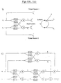
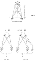
- the loudspeaker position compensation problem is illustrated by Figure 1(b) in outline and in Figure 1(c) in block diagram form.
- the signals u 1 and u 2 denote those produced in a conventional stereophonic recording.
- the digital filters A 1 and A 2 denote the transfer functions between the inputs to ideally placed virtual loudspeaker and the ears of the listener. Note also that since the positions of both the real sources and the virtual sources are assumed to be symmetric with respect to the listener, there are only two different filters in each 2-by-2 filter matrix.
- the matrix C ( z ) of electro-acoustic transfer functions defines the relationship between the vector of loudspeaker input signals [ ⁇ 1 ( n ) ⁇ 2 ( n )] and the vector of signals [ w 1 ( n ) w 2 ( n )] reproduced at the ears of a listener.
- the matrix of inverse filters H ( z ) is designed to ensure that the sum of the time averaged squared values of the error signals e 1 ( n ) and e 2 ( n ) is minimised.
- error signals quantify the difference between the signals [ w 1 ( n ) w 2 ( n )] reproduced at the listener's ears and the signals [ d 1 ( n ) d 2 ( n )] that are desired to be reproduced.
- these desired signals are defined as those that would be reproduced by a pair of virtual sources spaced well apart from the positions of the actual loudspeaker sources used for reproduction.
- the matrix of filters A (z) is used to define these desired signals relative to the input signals [ u 1 ( n ) u 2 ( n )] which are those normally associated with a conventional stereophonic recording.
- the elements of the matrices A (z) and C (z) describe the Head Related Transfer Function (HRTF) of the listener.
- HRTF Head Related Transfer Function
- HRTFs can be deduced in a number of ways as disclosed in PCT/GB95/02005.
- One technique which has been found particularly useful in the operation of the present invention is to make use of a pre-recorded database of HRTFs.
- the signals u 1 ( n ) and u 2 ( n ) are those associated with a conventional stereophonic recording and they are used as inputs to the matrix H (z) of inverse filters designed to ensure the reproduction of signals at the listener's ears that would be reproduced by the spaced apart virtual loudspeaker sources.
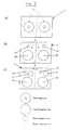
- Figure 2 shows three examples of how to configure different units of the two loudspeakers in a single cabinet.
- each loudspeaker 2 consists of only one full range unit, the two units should be positioned next to each other as in Figure 2(a).
- each loudspeaker consists of two or more units, these units can be placed in various ways, as illustrated by Figures 2(b) and 2(c) where low-frequency units 10, mid-frequency units 11, and high-frequency units 12 are also employed.
- the cross-talk cancellation matrix H x (z) has the following structure:
- H x ( z ) The elements of H x ( z ) can be calculated using the techniques described in detail in specification no. PCT/GB95/02005, preferably using the frequency domain approach described therein. Note that it is usually necessary to use regularisation to avoid the undesirable effects of ill-conditioning showing up in H x ( z ).
- the cross-talk cancellation matrix H x (z) is easiest to calculate when C (z) contains only relatively little detail. For example, it is much more difficult to invert a matrix of transfer functions measured in a reverberant room than a matrix of transfer functions measured in an anechoic room. Furthermore, it is reasonable to assume that a set of inverse filters whose frequency responses are relatively smooth is likely to sound 'more natural', or 'less coloured', than a set of filters whose frequency responses are wildly oscillating, even if both inversions are perfect at all frequencies. For that reason, we use a set of HRTFs taken from the MIT Media Lab's database which has been made available for researchers over the Internet.
- Each HRTF is the result of a measurement taken at every 5° in the horizontal plane in an anechoic chamber using a sampling frequency of 44.1 kHz.
- a sampling frequency of 44.1 kHz We use the 'compact' version of the database.
- Each HRTF has been equalised for the loudspeaker response before being truncated to retain only 128 coefficients (we also scaled the HRTFs to make their values lie within the range from -1 to +1).
- Figure 4 shows the frequency responses of H x1 ( z ) and H x2 ( z ) for the four different loudspeaker spans, namely a) 60°, b) 20°, c) 10°, and d) 5°.
- the filters used contain 1024 coefficients each, and they are calculated using the frequency domain inversion method described. No regularisation is used, but even so the undesirable wrap-around effect caused by the frequency sampling is not a serious problem, and the inversion is for all practical purposes perfect over the entire audio frequency range. Nevertheless, what is important is that the responses of H x1 ( z ) and H x2 ( z ) at very low frequencies increase as the angle ⁇ spanned by the loudspeakers is reduced.
- the performance of the virtual source imaging system is determined mainly by the effectiveness of the cross-talk cancellation.
- any signal can be reproduced at the left ear.
- the right ear because of the symmetry.
- head rotation, and head movement directly towards or away from the loudspeakers do not cause a significant reduction in the effectiveness of the cross-talk cancellation.
- the effectiveness of the cross-talk cancellation is quite sensitive to head movements to the side.
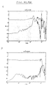
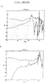
- Figure 6 shows the amplitude spectra of the reproduced signals for the two loudspeaker separations resulting in ⁇ values of 60° (a,c,e,g,i,k,m) and 10° (b,d,f,h,j,l,n) for the seven different values of dx -15cm (a,b), -10cm (c,d), - 5cm (e,f), 0cm (g,h), 5cm (i,j), 10cm (k,l), and 15cm (m,n). It is seen that when angle ⁇ is 60°, the cross-talk cancellation is efficient only up to about 1kHz even when the listener's head is moved as little as 5cm to the side.
- the cross-talk cancellation case considered in this section can be considered to be a 'worst case'.
- the virtual image is obviously very robust.
- the system will always perform better in practice when trying to create a virtual image than when trying to achieve a perfect cross-talk cancellation.
- the filter design procedure is based on the assumption that the loudspeakers behave like monopoles in a free field. It is clearly unrealistically optimistic to expect such a performance from a real loudspeaker. Nevertheless, virtual source imaging using the 'stereo dipole' arrangement of the present invention seems to work well in practice even when the loudspeakers are of very poor quality. It is particularly surprising that the system still works when the loudspeakers are not capable of generating any significant low-frequency output, as is the case for many of the small active loudspeakers used for multi-media applications. The single most important factor appears to be the difference between the frequency responses of the two loudspeakers. The system works well as long as the two loudspeakers have similar characteristics, that is, they are 'well matched'.
- two loudspeakers could be made to respond in substantially the same way be including an equalising filter on the input of one of the loudspeakers.
- a stereo system according to the present invention is generally very pleasant to listen to even though tests indicate that some listeners need some time to get used to it.
- the processing adds only insignificant colouration to the original recordings.
- the main advantage of the close loudspeaker arrangement is its robustness with respect to head movement which makes the 'bubble' that surrounds the listener's head comfortably big.
- One possible limitation of the present invention is that it cannot always create convincing virtual images directly to the side of, or behind, the listener. Convincing images can be created reliably only inside an arc spanning approximately 140 degrees in the horizontal plane (plus and minus 70 degrees relative to straight ahead) and approximately 90 degrees in the vertical plane (plus 60 and minus 30 degrees relative to the horizontal plane). Images behind the listener are often mirrored to the front. For example, if one attempts to create a virtual image directly behind the listener, it will be perceived as being directly in front of the listener instead. There is little one can do about this since the physical energy radiated by the loudspeakers will always approach the listener from the front. Of course, if rear images are required, one could place a further system according to the present invention directly behind the listener's head.
- n 1 and n 2 are assumed to be integers. It is straightforward to invert C (z) directly. Since n 1 ⁇ n 2 , the exact inverse is stable and can be implemented with an IIR (infinite impulse response) filter containing a single coefficient. Consequently, it would be very easy to implement in hardware. The quality of the sound reproduced by a system using filters designed this way is very 'unnatural' and 'coloured', though, but it might be good enough for applications such as games.
- IIR infinite impulse response
- each filter should contain at least 1024 coefficients (alternatively, this might be ahcieved by using a short IIR filter in combination with an FIR filter).
- Long inverse filters are most conveniently calculated by using a frequency domain method such as the one disclosed in PCT/GB95/02005.
- PCT/GB95/02005 there is currently no digital signal processing system commercially available that can implement such a system in real time. Such a system could be used for a domestic hi-end 'hi-fi' system or home theatre, or it could be used as a 'master' system which encodes broadcasts or recordings before further transmission or storage.
- Two loudspeakers (sources), separated by the distance ⁇ S, are positioned on the x 1 -axis symmetrically about the x 2 -axis.
- the ears of the listener are represented by two microphones, separated by the distance ⁇ M, that are also positioned symmetrically about the x 2 -axis (note that 'right ear' refers to the left microphone, and 'left ear' refers to the right microphone).
- the loudspeakers span an angle of ⁇ as seen from the position of the listener.
- V 1 , V 2 , W 1 , and W 2 are complex scalars.
- V j ⁇ 0 q 4 ⁇
- the aim of the system shown in Figure 7 is to reproduce a pair of desired signals D 1 and D 2 at the microphones. Consequently, we require W 1 to be equal to D 1 , and W 2 to be equal to D 2 .
- D 2 it is advantageous to define D 2 to be the product D times C 1 rather than just D since this guarantees that the time responses corresponding to the frequency response functions V 1 and V 2 are causal (in the time domain, this causes the desired signal to be delayed and scaled, but it does not affect its 'shape').
- this pulse At time ⁇ after reaching the left ear, this pulse reaches the listener's right ear where it is not intended to be heard, and consequently, it must be cancelled out by a negative pulse from the left loudspeaker.
- This negative pulse reaches the listener's right ear at time 2 ⁇ after the arrival of the first positive pulse, and so another positive pulse from the right loudspeaker is necessary, which in turn will create yet another unwanted negative pulse at the listener's left ear, and so on.
- the net result is that the right loudspeaker will emit a series of positive pulses whereas the left loudspeaker will emit a series of negative pulses.
- the individual pulses In each pulse train, the individual pulses are emitted with a 'ringing' frequency f 0 of 1/2 ⁇ .
- Figures 9a, 9b and 9c show the input to the two sources for the three different loudspeaker spans 60° ( Figure 9a), 20° ( Figure 9b), and 10° ( Figure 9c).
- the distance to the listener is 0.5m, and the microphone separation (head diameter) is 18cm.
- the desired signal is a Hanning pulse (one period of a cosine) specified by where ⁇ 0 is chosen to be 2 ⁇ times 3.2kHz (the spectrum of this pulse has its first zero at 6.4kHz, and so most of its energy is concentrated below 3kHz).
- the corresponding ringing frequencies f 0 are 1.9kHz, 5.5kHz, and, 11kHz respectively. If the listener does not sit too close to the sources, ⁇ is well approximated by assuming that the direct path and the cross-talk path are parallel lines, ⁇ ⁇ ⁇ M c 0 sin( ⁇ /2).
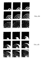
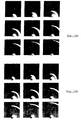
- Figures 10a, 10b, 10c and 10d show the sound field reproduced by four different source configurations: the three loudspeaker spans 60° (Figure 10a), 20° (Figure 10b), 10° (Figure 1 0c), and also the sound field generated by a superposition of a point monopole source and a point dipole source (Figure 10d).
- the sound fields plotted in Figures 10a, 10b, 10c are those generated by the source inputs plotted in Figures 9a, 9b and 9c.
- Each of the four plots of Figures 10a etc contain nine 'snapshots', or frames, of the sound field.
- the time increment between each frame is 0.1/ c 0 which is equivalent to the time it takes the sound to travel 10cm.
- Each frame is calculated at 101 ⁇ 101 points over an area of 1m ⁇ 1m (-0.5m ⁇ x 1 ⁇ 0.5m, 0 ⁇ x 2 ⁇ 1).
- the positions of the loudspeakers and the microphones are indicated by circles. Values greater than 1 are plotted as white, values smaller than -1 are plotted as black, values between -1 and 1 are shaded appropriately.
- Figure 10a illustrates the cross-talk cancellation principle when ⁇ is 60°. It is easy to identify a sequence of positive pulses from the right loudspeaker, and a sequence of negative pulses from the left loudspeaker. Both pulse trains are emitted with the ringing frequency 1.9kHz. Only the first pulse emitted from the right loudspeaker is actually 'seen' by the right microphone; consecutive pulses are cancelled out both at the left and right microphone. However, many 'copies' of the original Hanning pulse are seen at other locations in the sound field, even very close to the two microphones, and so this set-up is not very robust with respect to head movement.
- Figure 10d shows the sound field reproduced by a superposition of point monopole and point-dipole sources. This source combination avoids ringing completely, and so the reproduced field is very 'clean'. In the case of the two monopoles spanning 10°, it also contains a near-field component as expected. Note the similarity between the plots in Figure 10c and 10d. This means that moving the loudspeakers even closer together will not make any difference to the reproduced sound field.
- the reproduced sound field will be similar to that produced by a point monopole-dipole combination as long as the highest frequency component in the desired signal is significantly smaller than the ringing frequency f 0 .
- the ringing frequency can be increased by reducing the loudspeaker span ⁇ , but if ⁇ is too small, a very large output from the loudspeakers is necessary in order to achieve accurate cross-talk cancellation at low frequencies. In practice, a loudspeaker span of 10° is a good compromise.
- Figures 11a and 11b which are equivalent to Figures 10a and 10c respectively.
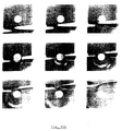
- Figures 11a and 11b illustrate the sound field that is reproduced in the vicinity of a rigid sphere by a pair of loudspeakers whose inputs are adjusted to achieve perfect cross-talk cancellation at the 'listener's' right ear.
- the analysis used to calculate the scattered sound field assumes that the incident wavefronts are plane. This is equivalent to assuming that the two loudspeakers are very far away.
- the diameter of the sphere is 18cm, and the reproduced sound field is calculated at 31 ⁇ 31 points over a 60cmx60cm square.
- the desired signal is the same as that used for the free-field example; it is a Hanning pulse whose main energy is concentrated below 3kHz.
- Figure 11a is concerned with a loudspeaker span of 60°, whereas Figure 11b is concerned with a loudspeaker span of 10°.
- a digital filter design procedure of the type described below was employed.
- the virtual source imaging problem is illustrated in Figure 8a.
- a monopole source is positioned somewhere in the listening space.
- the transfer functions from this source to the listener's ears are of the same type as C 1 and C 2 , and they are denoted by A 1 and A 2 .
- a 1 and A 2 the transfer functions from this source to the listener's ears.
- each source input is now the convolution of D with the sum of two decaying trains of delta functions, one positive and one negative. This is not surprising since the sources have to reproduce two positive pulses rather than just one.
- the 'positive part' of ⁇ 1 ( t ) combined with the 'negative part' of ⁇ 2 ( t ) produces the pulse at the listener's left ear whereas the 'negative part' of ⁇ 1 ( t ) combined with the 'positive part' of ⁇ 2 ( t ) produces the pulse at the listener's right ear.
- Figures 11a etc show the source inputs equivalent to those plotted in Figure 9a etc (three different loudspeaker spans ⁇ : 60°, 20°, and 10°), but for a virtual source imaging system rather than a cross-talk cancellation system.
- the virtual source is positioned at (1m,0m) which means that it is at an angle of 45° to the left relative to straight front as seen by the listener.
- ⁇ 60°
- Figure 12a both the positive and the negative pulse trains can be seen clearly in ⁇ 1 ( t ) and ⁇ 2 ( t ).
- ⁇ is reduced to 20°
- Figure 12c the positive and negative pulse trains start to cancel out. This is even more evident when ⁇ is 10° ( Figure 12c).
- the two source inputs look roughly like square pulses of relatively short duration (this duration is given by the difference in arrival time at the microphones of a pulse emitted from the virtual source).
- This duration is given by the difference in arrival time at the microphones of a pulse emitted from the virtual source.
- the advantage of the cancelling of the positive and negative parts of the pulse trains is that it greatly reduces the low-frequency content of the source inputs, and this is why virtual source imaging systems in practice are much easier to implement than cross-talk cancellation systems.
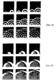
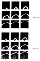
- Figures 13a, 13b, 13c and 13d show another four sets of nine 'snapshots' of the reproduced sound field which are equivalent to those shown by Figures 10a etc, but for a virtual source at (1m,0m) (indicated in the bottom right hand corner of each frame) rather than for a cross-talk cancellation system.
- the plots show how the reproduced sound field becomes simpler as the loudspeaker span is reduced.
- the limit Figure 13d
- the localisation mechanism is known to be more dependent on the difference in intensity between the two ears (although envelope shifts in high frequency signals can be detected). It is thus important to consider the shadowing, or diffraction, of the human head when implementing virtual source imaging systems in practice.
- Equation (8) The free-field transfer functions given by Equation (8) are useful for an analysis of the basic physics of sound reproduction, but they are of course only approximations to the exact transfer functions from the loudspeaker to the eardrums of the listener. These transfer functions are usually referred to as HRTFs (head-related transfer functions).
- HRTFs head-related transfer functions
- a rigid sphere is useful for this purpose as it allows the sound field in the vicinity of the head to be calculated numerically. However, it does not account for the influence of the listener's ears and torso on the incident sound waves. Instead, one can use measurements made on a dummy-head or a human subject. These measurements might, or might not, include the response of the room and the loudspeaker.
- Another important aspect to consider when trying to obtain a realistic HRTF is the distance from the source to the listener. Beyond a distance of, say, 1m, the HRTF for a given direction will not change substantially if the source is moved further away from the listener (not considering scaling and delaying). Thus, one would only need a single HRTF beyond a certain 'far-field' threshold. However, when the distance from the loudspeakers to the listener is short (as is the case when sitting in front of a computer), it seems reasonable to assume that it would be better to use 'distance-matched' HRTFs than 'far-field' HRTFs.
- the present invention employs a multi-channel filter design procedure that combines the principles of least squares approximation and regularisation (PCT/GB95/02005), calculating those causal and stable digital filters that ensure the minimisation of the squared error, defined in the frequency domain or in the time domain, between the desired ear signals and the reproduced ear signals.
- This filter design approach ensures that the signals reproduced at the listener's ears closely replicate the waveforms of the desired signals.
- the phase (arrival time) differences which are so important for the localisation mechanism, are correctly reproduced within a relatively large region surrounding the listener's head.
- the differences in intensity required to be reproduced at the listener's ears are also correctly reproduced.
- it is particularly important to include the HRTF of the listener, since this HRTF is especially important for determining the intensity differences between the ears at high frequencies.
- Regularisation is used to overcome the problem of ill-conditioning. Ill-conditioning is used to describe the problem that occurs when very large outputs from the loudspeakers are necessary in order to reproduce the desired signals (as is the case when trying to achieve perfect cross-talk cancellation at low frequencies using two closely spaced loudspeakers). Regularisation works by ensuring that certain pre-determined frequencies are not boosted by an excessive amount.
- a modelling delay means may be used in order to allow the filters to compensate for non-minimum phase components of the multi-channel plant (PCT/GB95/02005). The modelling delay causes the output from the filters to be delayed by a small amount, typically a few milliseconds.
- the objective of the filter design procedure is to determine a matrix of realisable digital filters that can be used to implement either a cross-talk cancellation system or a virtual source imaging system.
- the filter design procedure can be implemented either in the time domain, the frequency domain, or as a hybrid time/frequency domain method. Given an appropriate choice of the modelling delay and the regularisation, all implementations can be made to return the same optimal filters.
- Time domain filter design methods are particularly useful when the number of coefficients in the optimal filers is relatively small.
- the optimal filters can be found either by using an iterative method or by a direct method.
- the iterative method is very efficient in terms of memory usage, and it is also suitable for real-time implementation in hardware, but it converges relatively slowly.
- the direct method enables one to find the optimal filters by solving a linear equation system in the least squares sense.
- c 1 ( n ) and c 2 ( n ) are the impulse responses, each containing N c coefficients, of the electro-acoustic transfer functions from the loudspeakers to the ears of the listener.
- the modelling delay is included by delaying each of the two impulse responses that make up the right hand side d by the same amount m samples.
- V( k ) [C H ( k )C( k )+ ⁇ I] -1 C H ( k )D( k ).
- ⁇ is a regularisation parameter
- H denotes the Hermitian operator which transposes and conjugates its argument
- k corresponds to the k 'th frequency line; that is, the frequency corresponding to the complex number exp( j 2 ⁇ k / N v ).
- m is not critical; a value of N v /2 is likely to work well in all but a few cases. It is necessary to set the regularisation parameter ⁇ to an appropriate value, but the exact value of ⁇ is usually not critical, and can be determined by a few trial-and-error experiments.
- a related filter design technique uses the singular value decomposition method (SVD).
- SVD is well known to be useful in the solution of ill-conditioned inversion problems, and it can be applied at each frequency in turn.
- the fast deconvolution algorithm makes it practical to calculate the frequency response of the optimal filters at an arbitrarily large number of discrete frequencies, it is also possible to specify the frequency response of the optimal filters as a continuous function of frequency. A time domain method could then be used to approximate that frequency response. This has the advantage that a frequency-dependent leak could be incorporated into a matrix of short optimal filters.
- the two loudspeaker inputs must be very carefully matched. As shown in Figure 12, the two inputs are almost equal and opposite; it is mainly the very small time difference between them that guarantees that the arrival times of the sound at the ears of the listener are correct. In the following it is demonstrated that this is still the case for a range of virtual source image positions, even when the listener's head is modelled using realistic HRTFs.
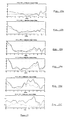
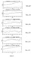
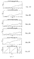
- Figures 14-20 compare the two inputs ⁇ 1 and ⁇ 2 to the loudspeakers for six different combinations of loudspeaker spans ⁇ and virtual source positions. Those combinations are as follows. For a loudspeaker span of 10 degrees a) image at 15 degrees, b) 30 degrees, c) 45 degrees, and d) 60 degrees. For the image at 45 degrees e) a loudspeaker span of 20 degrees and f) a span of 60 degrees. This information is also indicated on the individual plots. The image position is measured anti-clockwise relative to straight front which means that all the images are to the front left of the listener, and that they all fall outside the angle spanned by the loudspeakers.
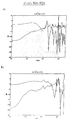
- FIG. 14 shows the impulse responses of v 1 ( n ) and v 2 ( n ). Each impulse response contains 128 coefficients, and they are calculated using a direct time domain method. Since the bandwidth is very high, the high frequencies make it difficult to see the structure of the responses, but even so it is still possible to appreciate that v 1 ( n ) is mainly positive whereas v 2 ( n ) is mainly negative.
- Figure 15 shows the magnitude, on a linear scale, of the frequency responses V 1 ( f ) and V 2 ( f ) of the impulse responses shown in Figure 14. It is seen that the two magnitude responses are qualitatively similar for the 10 degree loudspeaker span, and also for the 20 degree loudspeaker span. A relatively large output is required from both loudspeakers at low frequencies, but the responses decrease smoothly with frequency up to a frequency of approximately 2kHz. Between 2kHz and 4kHz the responses are quite smooth and relatively flat. For the 60 degree loudspeaker span, loudspeaker number one dominates over the entire frequency range.
- Figure 16 shows the ratio, on a linear scale, between the magnitudes of the frequency responses shown in Figure 15. It is seen that for the 10 degree loudspeaker span, the two magnitudes differ by less than a factor of two at almost all frequencies below 10kHz. The ratio between the two responses is particularly smooth at frequencies below 2kHz even though the two loudspeaker inputs are boosted moderately at low frequencies.
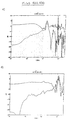
- Figure 17 shows the unwrapped phase response of the frequency responses shown in Figure 15.
- the phase contribution corresponding to a common delay has been removed from each of the six pairs (the six delays are, in sampling intervals, a) 31, b) 29, c) 28, d) 27, e) 29, and f) 33).
- the purpose of this is to make the resulting responses as flat as possible, otherwise each phase response will have a large negative slope that makes it impossible to see any detail in the plots. It is seen that the two phase responses are almost flat for the 10 degree loudspeaker span whereas the phase responses corresponding to the loudspeaker spans of 20 degrees and 60 degrees (plot f, note range of y-axis) have distinctly different slopes.
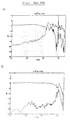
- Figure 18 shows the difference between the phase responses shown in Figure 17. It is seen that for the 10 degree loudspeaker span the difference is within -pi and 0. This means that at no frequencies below 10kHz with a loudspeaker span ⁇ of 10 degrees are the two loudspeaker inputs in phase. At frequencies below 8kHz, the phase difference between the two loudspeaker inputs is substantial and its absolute value is always greater than pi/4 (equivalent to 45 degrees). At frequencies below 100Hz, the two loudspeaker inputs are very close to being exactly out of phase.
- the phase difference is between -pi radians and -pi+1 radians (equivalent to -180 degrees and -120 degrees), and at frequencies below 4kHz the phase difference is between -pi and -pi+pi/2 (equivalent to -180 degrees and -90 degrees).
- the loudspeaker spans of 20 degrees and 60 degrees. This confirms that in order to create virtual source images outside the angle spanned by the loudspeakers, the inputs to the stereo dipole must be almost, but not quite, out of phase over a substantial frequency range.
- the frequency responses of the two loudspeakers are substantially the same, then the phase difference between the vibrations of the loudspeakers will be substantially the same as the phase difference between the inputs to the loudspeakers.
- the two loudspeakers vibrate substantially in phase with each other when the same input signal is applied to each loudspeaker.
- the free-field analysis suggests that the lowest frequency at which the two loudspeaker inputs are in phase is the "ringing" frequency.
- the ringing frequencies are 1.8kHz, 5.4kHz, and 10.8kHz respectively, and this is in good agreement with the frequencies at which the first zero-crossing in Figure 18 occur.
- the two loudspeaker inputs are always exactly out of phase at frequency 0Hz. Note also that an exact match of the phase responses is still important at high frequencies even though the human localisation mechanism is not sensitive to time differences at high frequencies.
- the illusion of the virtual source image will break down for signals whose main energy is concentrated within that frequency range, such as a third octave band noise signal.
- the illusion might still work as long as the phase response is correctly matched over a substantial frequency range.
- the difference in phase responses noted here will also result in similar differences in vibrations of the loudspeakers.
- the loudspeaker vibrations will be close to 180° out of phase at low frequencies (eg less than 2kHz when a loudspeaker span of about 10° is used).
- Figure 19 shows v 1 ( n ) and - v 2 ( n ) in the case when the desired waveform is a Hanning pulse whose bandwidth is approximately 3kHz (the same as that used for the free-field analysis, see Figures 12 and 13).
- v 2 ( n ) is inverted in order to show how similar it is to v 1 ( n ). It is the small difference between the two pulses that ensures that the arrival times of the sound at the listener's ear are correct. Note how well the results shown in Figure 19 agree with the results shown in Figure 12 (Figure 19c corresponds to Figure 12c, 19e to 12b, and 19f to 12a).
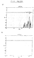
- Figure 20 shows the difference between the impulse responses plotted in Figure 19. Since ⁇ 2 ( n ) is inverted in Figure 19, this difference is the sum of ⁇ 1 ( n ) and ⁇ 2 ( n ). It is seen that for the 10 degree loudspeaker span it is the tiny time difference between the onset of the two pulses that contributes most to the sum signal.
- the importance of specifying the cross-talk cancellation filters very accurately is now demonstrated by considering the properties of a set of filters calculated using a frequency domain method.
- the filters each contain 1024 coefficients, and the head-related transfer functions are taken from the MIT database.
- the diagonal element of H is denoted h 1
- the off-diagonal element is denoted h 2 .
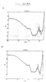
- Figure 21 shows the magnitude and phase response of the two filters H 1 ( f ) and H 2 ( f ).
- Figure 21a shows their magnitude responses
- 21 b shows the difference between the two.
- Figure 21c shows their unwrapped phase responses (after removing a common delay corresponding to 224 samples), and
- Figure 21 d shows the difference between the two. It is seen that the dynamic range of H 1 ( f ) and H 2 ( f ) is approximately 35dB, but even so the difference between the two is quite small (within 5dB at frequencies below 8kHz). As with virtual source imaging using the 10 degree loudspeaker span, the two filters are not in phase at any frequency below 10kHz, and for frequencies below 8kHz the absolute value of the phase difference is always greater than than pi/4 radians (equivalent to 45 degrees).
- Figure 22 shows the Hanning pulse response of the two filters (a) and their sum (b). It is clear that the two impulse responses are extremely close to being exactly equal and opposite. Thus, if H 1 ( f ) and H 2 ( f ) are not implemented exactly according to their specifications, the performance of the system in practice is likely to suffer severely.
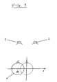
- Figure 23 shows the signals reproduced at the ears of the listener when the head is displaced by 5cm directly to the left (towards the virtual source, see Figure 5). It is seen that the performance of the 10 degree loudspeaker span is not noticably affected whereas the signals reproduced at the ears of the listener by a loudspeaker arrangement spanning 60 degrees are not quite the same as the desired signals.
- Figure 24 shows the signals reproduced at the ears of the listener when the head is displaced by 5cm directly to the right (away from the virtual source). This causes a serious degradation of the performance of a loudspeaker arrangement spanning 60 degrees even though the virtual source is quite close to the left loudspeaker. The image produced by the 10 degree loudspeaker span, however, is still noticably affected by the displacement of the head.
- the stereo dipole can also be used to transmit five channel recordings.
- appropriately designed filters may be used to place virtual loudspeaker positions both in front of, and behind, the listener.
- virtual loudspeakers would be equivalent to those normally used to transmit the five channels of the recording.
- a second stereo dipole can be placed directly behind the listener.
- a second rear dipole could be used, for example, to implement two rear surround speakers. It is also conceivable that two closely spaced loudspeakers placed one on top of the other could greatly improve the perceived quality of virtual images outside the horizontal plane.
- a combination of multiple stereo dipoles could be used to achieve full 3D-surround sound.
- stereo dipoles When several stereo dipoles are used to cater for several listeners, the cross-talk between stereo dipoles can be compensated for using digital filter design techniques of the type described above.
- digital filter design techniques of the type described above.
- Such systems may be used, for example, by in-car entertainment systems and by teleconferencing systems.
- a sound recording for subsequent play through a closely-spaced pair of loudspeakers may be manufactured by recording the output signals from the filters of a system according to the present invention.
- output signals v 1 and v 2 would be recorded and the recording subsequently played through a closely-spaced pair of loudspeakers incorporated, for example, in a personal player.
- 'stereo dipole' is used to describe the present invention
- 'monopole' is used to describe an idealised acoustic source of fluctuating volume velocity at a point in space
- 'dipole' is used to describe an idealised acoustic source of fluctuating force applied to the medium at a point in space.
- More than two loudspeakers may be used, as may a single sound channel input, (as in Figures 8(a) and 8(b)).
- transducer means in substitution for conventional moving coil loudspeakers.
- piezo-electric or piezo-ceramic actuators could be used in embodiments of the invention when particularly small transducers are required for compactness.
Landscapes
- Physics & Mathematics (AREA)
- Engineering & Computer Science (AREA)
- Acoustics & Sound (AREA)
- Signal Processing (AREA)
- Stereophonic System (AREA)
Claims (24)
- Tonwiedergabesystem (1) mit Lautsprechermitteln (2) und Lautsprecher-Treibermitteln (3) zum Treiben der Lautsprechermittel in Reaktion auf Signale von zumindest einem Tonkanal, wobei die Lautsprechermittel ein dicht beabstandetes Paar von Lautsprechern umfaßt, wobei die Lautsprecher-Treibermittel Filtermittel (H1(z), H2(z)) umfassen, wobei die Filtermittel zumindest ein Paar von Filtern umfassen, wobei der Ausgang von einem Filter (H1(z)) des Paars von Filtern auf einen Lautsprecher (2) des Paars von Lautsprechern angewendet wird, wobei der Ausgang des anderen Filters (H2(z)) des Paars von Filtern auf den anderen Lautsprecher des Paars von Lautsprechern angewendet wird, wobei die Charakteristiken der Filtermittel derart gewählt werden, daß sie virtuelle Bilder von Tonquellen erzeugen, die mit dem Tonkanal/den Tonkanälen (4) an virtuellen Quellenpositionen im Zusammenhang stehen, die in einer bestimmten Zuhörerposition (8) einen Winkel aufspannen, der wesentlich größer als der Winkel () ist, der von den Lautsprechern aufgespannt wird, dadurch gekennzeichnet, daß die Lautsprecher mit der Zuhörerposition (8) einen spitzen Winkel () zwischen einschließlich 6° und 20° definieren, und daß die Ausgänge (V1, V2) des Paars von Filtern zu einer Phasendifferenz zwischen den Vibrationen der beiden Lautsprecher (2) führen, wobei sich die Phasendifferenz mit der Frequenz von niedrigen Frequenzen, wo die Vibrationen im wesentlichen außer Phase sind, zu hohen Frequenzen verändert, wo die Vibrationen in Phase sind, wobei die niedrigste Frequenz, bei der die Vibrationen in Phase sind, näherungsweise durch eine Abklingfrequenz f 0 festgelegt wird, die definiert ist durch
- Tonwiedergabesystem nach Anspruch 1, bei dem der spitze Winkel () zwischen einschließlich 8° und 12° beträgt.
- Tonwiedergabesystem nach Anspruch 2, bei dem der spitze Winkel () ungefähr 10° beträgt.
- Tonwiedergabesystem nach Anspruch 3, bei dem die Filtermittel derart angeordnet sind, daß die Reproduktion gewünschter, mit einer virtuellen Quelle im Zusammenhang stehender Signale in dem Bereich der Zuhörerohren bis zu ungefähr 4 kHz effizient ist, selbst wenn sich der Zuhörerkopf (6) von der vorbestimmten Zuhörerposition (8) 10 cm zur Seite bewegt.
- Tonwiedergabesystem nach Anspruch 1, bei dem der Außer-Phase-Frequenzbereich den Bereich von 100 Hz bis 4 kHz umfaßt.
- Tonwiedergabesystem nach einem der vorhergehenden Ansprüche, bei dem die beiden Lautsprecher im wesentlichen miteinander in Phase vibrieren, wenn das gleiche Eingangssignal (V1, V2) an jeden Lautsprecher angelegt wird.
- Tonwiedergabesystem nach Anspruch 6, bei dem die Eingangssignale zu den beiden Lautsprechern über einen Frequenzbereich von 100 Hz bis 4 kHz niemals in Phase sind.
- Tonwiedergabesystem nach einem der vorhergehenden Ansprüche, bei dem die Filtermittel durch Einsatz einer Annäherung kleinster Quadrate entworfen werden.
- Tonwiedergabesystem nach Anspruch 8, bei dem eine wesentliche Minimierung des quadratischen Fehlers zwischen gewünschten Ohrsignalen und reproduzierten Ohrsignalen derart geschieht, daß die bei den Zuhörerohren reproduzierten Signale im wesentlichen die Wellenformen der gewünschten Signale nachbilden.
- Tonwiedergabesystem nach einem der vorhergehenden Ansprüche, bei dem die Filtermittel mit kopfbezogenen Übergangsfunktionsmitteln (HRTF) ausgestattet sind.
- Tonwiedergabesystem nach Anspruch 10, bei dem die kopfbezogenen Übergangsfunktionen durch die Verwendung einer Matrix von Filtern nachgebildet werden.
- Tonwiedergabesystem nach einem der vorhergehenden Ansprüche, ausgestattet mit Reguliermitteln, die betriebsfähig sind, um das Verstärken bestimmter Signalfrequenzen zu begrenzen.
- Tonwiedergabesystem nach einem der vorhergehenden Ansprüche, ausgestattet mit Modellierverzögerungsmitteln.
- Tonwiedergabesystem nach einem der vorhergehenden Ansprüche, bei dem der Abstand ΔS zwischen den Zentren der Lautsprecher nicht mehr als ungefähr 45 cm beträgt.
- Tonwiedergabesystem nach einem der vorhergehenden Ansprüche, bei dem die optimale Position zum Zuhören bei einer Kopfposition (8) ist, die in einem Abstand (r 0) von zwischen 0,2 m und 4,0 m von den Lautsprechern liegt.
- Tonwiedergabesystem nach Anspruch 15, bei dem die Kopfposition in einem Abstand (r 0) von zwischen 0,2 m und 1,0 m von den Lautsprechern liegt.
- Tonwiedergabesystem nach Anspruch 15, bei dem die Kopfposition ungefähr 2,0 m von den Lautsprechern entfernt liegt.
- Tonwiedergabesystem nach einem der vorhergehenden Ansprüche, bei dem die Lautsprecherzentren im wesentlichen parallel zueinander angeordnet sind.
- Tonwiedergabesystem nach einem der Ansprüche 1 bis 17, bei dem die Achsen der Lautsprecherzentren auf eine konvergente Weise zueinander geneigt sind.
- Tonwiedergabesystem nach einem der vorhergehenden Ansprüche, bei dem die Lautsprecher (2) in einem einzigen Gehäuse (7) aufgenommen sind.
- Tonwiedergabesystem nach einem der vorhergehenden Ansprüche, bei dem die Filtermittel zwei Paare von Filtern umfassen, wobei jeder von ihnen auf einem Kanal einer Zweikanalstereoaufzeichnung betrieben wird.
- Tonwiedergabesystem nach einem der vorhergehenden Ansprüche, bei dem die Lautsprecher-Treibermittel für die Kanäle einer konventionellen Tonaufzeichnung ansprechempfindlich sind.
- Filtermittel (H), ausgelegt, um bei den Lautsprecher-Treibermitteln eines Tonwiedergabesystems nach einem der vorhergehenden Ansprüche einsetzbar zu sein.
- Verfahren zum Erzeugen einer Tonaufzeichnung zum Abspielen über ein dicht beabstandetes Paar von Lautsprechern (2), die mit einer bestimmten Zuhörerposition (8) einen spitzen Winkel () von zwischen einschließlich 6° und 20° definieren, unter Verwendung von Stereoverstärkern, wobei Filtermittel (H) beim Erzeugen der Tonaufzeichnung von Tonsignalen eingesetzt werden, die ansonsten zum Abspielen unter Verwendung von Stereoverstärkern über ein Paar von Lautsprechern geeignet sind, die einen Winkel bei der beabsichtigten Zuhörerposition (8) aufspannen, der wesentlich größer als 20° ist, wodurch die Notwendigkeit vermieden wird, virtuelle Abbildungsfiltermittel bei den Eingängen der Lautsprecher vorzusehen, um virtuelle Tonquellen zu erzeugen, wobei die Filtermittel (H), die beim Erzeugen der Tonaufzeichnungen eingesetzt werden, die gleichen Charakteristiken wie die Filtermittel von Anspruch 23 aufweisen.
Applications Claiming Priority (3)
| Application Number | Priority Date | Filing Date | Title |
|---|---|---|---|
| GB9603236 | 1996-02-16 | ||
| GBGB9603236.2A GB9603236D0 (en) | 1996-02-16 | 1996-02-16 | Sound recording and reproduction systems |
| PCT/GB1997/000415 WO1997030566A1 (en) | 1996-02-16 | 1997-02-14 | Sound recording and reproduction systems |
Publications (2)
| Publication Number | Publication Date |
|---|---|
| EP0880871A1 EP0880871A1 (de) | 1998-12-02 |
| EP0880871B1 true EP0880871B1 (de) | 2003-11-19 |
Family
ID=10788840
Family Applications (1)
| Application Number | Title | Priority Date | Filing Date |
|---|---|---|---|
| EP97903466A Expired - Lifetime EP0880871B1 (de) | 1996-02-16 | 1997-02-14 | Tonaufnahme- und -wiedergabesysteme |
Country Status (6)
| Country | Link |
|---|---|
| US (2) | US6760447B1 (de) |
| EP (1) | EP0880871B1 (de) |
| JP (1) | JP4508295B2 (de) |
| DE (1) | DE69726262T2 (de) |
| GB (1) | GB9603236D0 (de) |
| WO (1) | WO1997030566A1 (de) |
Cited By (1)
| Publication number | Priority date | Publication date | Assignee | Title |
|---|---|---|---|---|
| US9131305B2 (en) | 2012-01-17 | 2015-09-08 | LI Creative Technologies, Inc. | Configurable three-dimensional sound system |
Families Citing this family (59)
| Publication number | Priority date | Publication date | Assignee | Title |
|---|---|---|---|---|
| EP0905933A3 (de) * | 1997-09-24 | 2004-03-24 | STUDER Professional Audio AG | Verfahren und Vorrichtung zum Mischen von Tonsignalen |
| US7113609B1 (en) * | 1999-06-04 | 2006-09-26 | Zoran Corporation | Virtual multichannel speaker system |
| US7010128B1 (en) * | 1999-11-25 | 2006-03-07 | Embracing Sound Experience Ab | Method of processing and reproducing an audio stereo signal and an audio stereo signal reproduction system |
| DE19956690A1 (de) | 1999-11-25 | 2001-07-19 | Harman Audio Electronic Sys | Beschallungseinrichtung |
| JP2001340522A (ja) * | 2000-05-31 | 2001-12-11 | Heiwa Corp | 遊技機枠体 |
| GB0015419D0 (en) | 2000-06-24 | 2000-08-16 | Adaptive Audio Ltd | Sound reproduction systems |
| DE60228529D1 (de) * | 2001-07-30 | 2008-10-09 | Matsushita Electric Industrial Co Ltd | Schallwiedergabeeinrichtung |
| WO2005006811A1 (fr) * | 2003-06-13 | 2005-01-20 | France Telecom | Traitement de signal binaural a efficacite amelioree |
| JP4171675B2 (ja) * | 2003-07-15 | 2008-10-22 | パイオニア株式会社 | 音場制御システム、および音場制御方法 |
| SE527062C2 (sv) | 2003-07-21 | 2005-12-13 | Embracing Sound Experience Ab | Stereoljudbehandlingsmetod, -anordning och -system |
| KR20060022968A (ko) * | 2004-09-08 | 2006-03-13 | 삼성전자주식회사 | 음향재생장치 및 음향재생방법 |
| US7634092B2 (en) * | 2004-10-14 | 2009-12-15 | Dolby Laboratories Licensing Corporation | Head related transfer functions for panned stereo audio content |
| EP1825713B1 (de) * | 2004-11-22 | 2012-10-17 | Bang & Olufsen A/S | Verfahren und Vorrichtung für Mehrkanal-Aufwärtsmischung und -Abwärtsmischung |
| US7991176B2 (en) * | 2004-11-29 | 2011-08-02 | Nokia Corporation | Stereo widening network for two loudspeakers |
| US7184557B2 (en) * | 2005-03-03 | 2007-02-27 | William Berson | Methods and apparatuses for recording and playing back audio signals |
| JP2006279864A (ja) * | 2005-03-30 | 2006-10-12 | Clarion Co Ltd | 音響システム |
| WO2006109312A2 (en) * | 2005-04-15 | 2006-10-19 | Vascular Biogenics Ltd. | Compositions containing beta 2-glycoprotein i-derived peptides for the prevention and/or treatment of vascular disease |
| CN101263741B (zh) * | 2005-09-13 | 2013-10-30 | 皇家飞利浦电子股份有限公司 | 产生和处理表示hrtf的参数的方法和设备 |
| US8243967B2 (en) | 2005-11-14 | 2012-08-14 | Nokia Corporation | Hand-held electronic device |
| KR100754220B1 (ko) * | 2006-03-07 | 2007-09-03 | 삼성전자주식회사 | Mpeg 서라운드를 위한 바이노럴 디코더 및 그 디코딩방법 |
| SE530180C2 (sv) | 2006-04-19 | 2008-03-18 | Embracing Sound Experience Ab | Högtalaranordning |
| WO2007119058A1 (en) * | 2006-04-19 | 2007-10-25 | Big Bean Audio Limited | Processing audio input signals |
| EP1858296A1 (de) * | 2006-05-17 | 2007-11-21 | SonicEmotion AG | Verfahren und System zur Erzeugung eines binauralen Eindrucks mittels Lautsprecher |
| WO2008047833A1 (en) | 2006-10-19 | 2008-04-24 | Panasonic Corporation | Sound image positioning device, sound image positioning system, sound image positioning method, program, and integrated circuit |
| US8705748B2 (en) * | 2007-05-04 | 2014-04-22 | Creative Technology Ltd | Method for spatially processing multichannel signals, processing module, and virtual surround-sound systems |
| WO2008135049A1 (en) * | 2007-05-07 | 2008-11-13 | Aalborg Universitet | Spatial sound reproduction system with loudspeakers |
| US8229143B2 (en) * | 2007-05-07 | 2012-07-24 | Sunil Bharitkar | Stereo expansion with binaural modeling |
| WO2009022463A1 (ja) | 2007-08-13 | 2009-02-19 | Mitsubishi Electric Corporation | オーディオ装置 |
| US8144902B2 (en) * | 2007-11-27 | 2012-03-27 | Microsoft Corporation | Stereo image widening |
| KR101476139B1 (ko) * | 2007-11-28 | 2014-12-30 | 삼성전자주식회사 | 가상 스피커를 이용한 음원 신호 출력 방법 및 장치 |
| JP5317465B2 (ja) * | 2007-12-12 | 2013-10-16 | アルパイン株式会社 | 車載音響システム |
| JP4518151B2 (ja) * | 2008-01-15 | 2010-08-04 | ソニー株式会社 | 信号処理装置、信号処理方法、プログラム |
| US8391498B2 (en) | 2008-02-14 | 2013-03-05 | Dolby Laboratories Licensing Corporation | Stereophonic widening |
| US20090324002A1 (en) * | 2008-06-27 | 2009-12-31 | Nokia Corporation | Method and Apparatus with Display and Speaker |
| US9247369B2 (en) * | 2008-10-06 | 2016-01-26 | Creative Technology Ltd | Method for enlarging a location with optimal three-dimensional audio perception |
| US8891781B2 (en) * | 2009-04-15 | 2014-11-18 | Pioneer Corporation | Active vibration noise control device |
| EP3255903B1 (de) | 2009-08-03 | 2022-12-07 | IMAX Corporation | Systeme und verfahren zur überwachung von kinolautsprechern und zur kompensation von qualitätsproblemen |
| JP5672741B2 (ja) * | 2010-03-31 | 2015-02-18 | ソニー株式会社 | 信号処理装置および方法、並びにプログラム |
| CN103222187B (zh) * | 2010-09-03 | 2016-06-15 | 普林斯顿大学托管会 | 对于通过扬声器的音频的频谱不着色的优化串扰消除 |
| CN105898641A (zh) * | 2010-10-02 | 2016-08-24 | 张沈平 | 一种耳机、相应的音源设备以及控制方法 |
| CN103181191B (zh) | 2010-10-20 | 2016-03-09 | Dts有限责任公司 | 立体声像加宽系统 |
| WO2012094338A1 (en) | 2011-01-04 | 2012-07-12 | Srs Labs, Inc. | Immersive audio rendering system |
| US20120294446A1 (en) * | 2011-05-16 | 2012-11-22 | Qualcomm Incorporated | Blind source separation based spatial filtering |
| JP2013157747A (ja) | 2012-01-27 | 2013-08-15 | Denso Corp | 音場制御装置及びプログラム |
| WO2015032009A1 (es) * | 2013-09-09 | 2015-03-12 | Recabal Guiraldes Pablo | Método y sistema de tamaño reducido para la decodificación de señales de audio en señales de audio binaural |
| US9749769B2 (en) | 2014-07-30 | 2017-08-29 | Sony Corporation | Method, device and system |
| CN106664499B (zh) * | 2014-08-13 | 2019-04-23 | 华为技术有限公司 | 音频信号处理装置 |
| US9560464B2 (en) | 2014-11-25 | 2017-01-31 | The Trustees Of Princeton University | System and method for producing head-externalized 3D audio through headphones |
| USD767635S1 (en) * | 2015-02-05 | 2016-09-27 | Robert Bosch Gmbh | Equipment for reproduction of sound |
| MX367239B (es) | 2015-02-16 | 2019-08-09 | Huawei Tech Co Ltd | Un aparato de procesamiento de señal de audio y un metodo para la reduccion de diafonia de una señal de audio. |
| JP6561718B2 (ja) * | 2015-09-17 | 2019-08-21 | 株式会社Jvcケンウッド | 頭外定位処理装置、及び頭外定位処理方法 |
| JP6546698B2 (ja) * | 2015-09-25 | 2019-07-17 | フラウンホーファー−ゲゼルシャフト ツル フェルデルング デル アンゲヴァンテン フォルシュング エー ファウFraunhofer−Gesellschaft zur Foerderung der angewandten Forschung e.V. | レンダリングシステム |
| US10595150B2 (en) * | 2016-03-07 | 2020-03-17 | Cirrus Logic, Inc. | Method and apparatus for acoustic crosstalk cancellation |
| US10111001B2 (en) | 2016-10-05 | 2018-10-23 | Cirrus Logic, Inc. | Method and apparatus for acoustic crosstalk cancellation |
| FR3091632B1 (fr) * | 2019-01-03 | 2022-03-11 | Parrot Faurecia Automotive Sas | Procédé de détermination d’un filtre de phase pour un système de génération de vibrations perceptibles par un utilisateur comprenant plusieurs transducteurs |
| CN115715470B (zh) | 2019-12-30 | 2025-11-18 | 卡姆希尔公司 | 用于提供空间化声场的方法 |
| US11581004B2 (en) | 2020-12-02 | 2023-02-14 | HearUnow, Inc. | Dynamic voice accentuation and reinforcement |
| US12223853B2 (en) | 2022-10-05 | 2025-02-11 | Harman International Industries, Incorporated | Method and system for obtaining acoustical measurements |
| JP2024122274A (ja) * | 2023-02-28 | 2024-09-09 | キヤノン株式会社 | 制御装置、制御方法、及びプログラム |
Family Cites Families (6)
| Publication number | Priority date | Publication date | Assignee | Title |
|---|---|---|---|---|
| DE3630692A1 (de) | 1985-09-10 | 1987-04-30 | Canon Kk | Tonsignaluebertragungssystem |
| US4893342A (en) * | 1987-10-15 | 1990-01-09 | Cooper Duane H | Head diffraction compensated stereo system |
| ATE120328T1 (de) | 1988-07-08 | 1995-04-15 | Adaptive Audio Ltd | Tonwiedergabesysteme. |
| WO1994001981A2 (en) | 1992-07-06 | 1994-01-20 | Adaptive Audio Limited | Adaptive audio systems and sound reproduction systems |
| US5553147A (en) | 1993-05-11 | 1996-09-03 | One Inc. | Stereophonic reproduction method and apparatus |
| GB9417185D0 (en) | 1994-08-25 | 1994-10-12 | Adaptive Audio Ltd | Sounds recording and reproduction systems |
-
1996
- 1996-02-16 GB GBGB9603236.2A patent/GB9603236D0/en active Pending
-
1997
- 1997-02-14 DE DE69726262T patent/DE69726262T2/de not_active Expired - Lifetime
- 1997-02-14 EP EP97903466A patent/EP0880871B1/de not_active Expired - Lifetime
- 1997-02-14 WO PCT/GB1997/000415 patent/WO1997030566A1/en not_active Ceased
- 1997-02-14 US US09/125,308 patent/US6760447B1/en not_active Expired - Fee Related
- 1997-02-14 JP JP52910697A patent/JP4508295B2/ja not_active Expired - Fee Related
-
2004
- 2004-03-11 US US10/797,973 patent/US7072474B2/en not_active Expired - Fee Related
Cited By (1)
| Publication number | Priority date | Publication date | Assignee | Title |
|---|---|---|---|---|
| US9131305B2 (en) | 2012-01-17 | 2015-09-08 | LI Creative Technologies, Inc. | Configurable three-dimensional sound system |
Also Published As
| Publication number | Publication date |
|---|---|
| JP4508295B2 (ja) | 2010-07-21 |
| DE69726262T2 (de) | 2004-09-09 |
| JP2000506691A (ja) | 2000-05-30 |
| GB9603236D0 (en) | 1996-04-17 |
| US6760447B1 (en) | 2004-07-06 |
| US20040170281A1 (en) | 2004-09-02 |
| WO1997030566A1 (en) | 1997-08-21 |
| EP0880871A1 (de) | 1998-12-02 |
| DE69726262D1 (de) | 2003-12-24 |
| US7072474B2 (en) | 2006-07-04 |
Similar Documents
| Publication | Publication Date | Title |
|---|---|---|
| US6760447B1 (en) | Sound recording and reproduction systems | |
| Davis et al. | High order spatial audio capture and its binaural head-tracked playback over headphones with HRTF cues | |
| EP2206365B1 (de) | Verfahren und Vorrichtung für erhöhte Klangfeldwiedergabepräzision in einem bevorzugten Zuhörbereich | |
| US5333200A (en) | Head diffraction compensated stereo system with loud speaker array | |
| US7215782B2 (en) | Apparatus and method for producing virtual acoustic sound | |
| KR101234973B1 (ko) | 필터 특징을 발생시키는 장치 및 방법 | |
| Snow | Basic principles of stereophonic sound | |
| Kirkeby et al. | Local sound field reproduction using two closely spaced loudspeakers | |
| Garas | Adaptive 3D sound systems | |
| EP3895451B1 (de) | Verfahren und vorrichtung zur verarbeitung eines stereosignals | |
| EP1761110A1 (de) | Methode zur Generation eines Multikanalaudiosignals aus Stereosignalen | |
| EP1728410B1 (de) | Verfahren und system zum verarbeiten von tonsignalen | |
| JP3217342B2 (ja) | ステレオフオニツクなバイノーラル録音または再生方式 | |
| Farina et al. | Ambiophonic principles for the recording and reproduction of surround sound for music | |
| KR100636252B1 (ko) | 공간 스테레오 사운드 생성 방법 및 장치 | |
| Ziemer | Psychoacoustic Sound Field Synthesis | |
| KR100647338B1 (ko) | 최적 청취 영역 확장 방법 및 그 장치 | |
| JP2001346298A (ja) | バイノーラル再生装置及び音源評価支援方法 | |
| JPS6013640B2 (ja) | ステレオ再生方式 | |
| Zotter et al. | Compact spherical loudspeaker arrays | |
| Linkwitz | The challenge to find the optimum radiation pattern and placement of stereo loudspeakers in a room for the creation of phantom sources and simultaneous masking of real sources | |
| Herbordt et al. | Wave field cancellation using wave-domain adaptive filtering | |
| Berkhout et al. | Generation of sound fields using wave field systhesis, an overview | |
| Hohnerlein | Beamforming-based Acoustic Crosstalk Cancelation for Spatial Audio Presentation | |
| Linkwitz et al. | Recording and Reproduction over Two Loudspeakers as Heard Live. Part 1: Hearing, Loudspeakers, and Rooms |
Legal Events
| Date | Code | Title | Description |
|---|---|---|---|
| PUAI | Public reference made under article 153(3) epc to a published international application that has entered the european phase |
Free format text: ORIGINAL CODE: 0009012 |
|
| 17P | Request for examination filed |
Effective date: 19980907 |
|
| AK | Designated contracting states |
Kind code of ref document: A1 Designated state(s): DE FR GB NL |
|
| 17Q | First examination report despatched |
Effective date: 20001208 |
|
| GRAH | Despatch of communication of intention to grant a patent |
Free format text: ORIGINAL CODE: EPIDOS IGRA |
|
| GRAS | Grant fee paid |
Free format text: ORIGINAL CODE: EPIDOSNIGR3 |
|
| GRAA | (expected) grant |
Free format text: ORIGINAL CODE: 0009210 |
|
| AK | Designated contracting states |
Kind code of ref document: B1 Designated state(s): DE FR GB NL |
|
| REG | Reference to a national code |
Ref country code: GB Ref legal event code: FG4D |
|
| REF | Corresponds to: |
Ref document number: 69726262 Country of ref document: DE Date of ref document: 20031224 Kind code of ref document: P |
|
| ET | Fr: translation filed | ||
| PLBE | No opposition filed within time limit |
Free format text: ORIGINAL CODE: 0009261 |
|
| STAA | Information on the status of an ep patent application or granted ep patent |
Free format text: STATUS: NO OPPOSITION FILED WITHIN TIME LIMIT |
|
| 26N | No opposition filed |
Effective date: 20040820 |
|
| PGFP | Annual fee paid to national office [announced via postgrant information from national office to epo] |
Ref country code: NL Payment date: 20090224 Year of fee payment: 13 |
|
| PGFP | Annual fee paid to national office [announced via postgrant information from national office to epo] |
Ref country code: DE Payment date: 20100428 Year of fee payment: 14 |
|
| REG | Reference to a national code |
Ref country code: NL Ref legal event code: V1 Effective date: 20100901 |
|
| PG25 | Lapsed in a contracting state [announced via postgrant information from national office to epo] |
Ref country code: NL Free format text: LAPSE BECAUSE OF NON-PAYMENT OF DUE FEES Effective date: 20100901 |
|
| REG | Reference to a national code |
Ref country code: DE Ref legal event code: R119 Ref document number: 69726262 Country of ref document: DE Effective date: 20110901 |
|
| PGFP | Annual fee paid to national office [announced via postgrant information from national office to epo] |
Ref country code: GB Payment date: 20130227 Year of fee payment: 17 Ref country code: FR Payment date: 20130321 Year of fee payment: 17 |
|
| PG25 | Lapsed in a contracting state [announced via postgrant information from national office to epo] |
Ref country code: DE Free format text: LAPSE BECAUSE OF NON-PAYMENT OF DUE FEES Effective date: 20110901 |
|
| GBPC | Gb: european patent ceased through non-payment of renewal fee |
Effective date: 20140214 |
|
| REG | Reference to a national code |
Ref country code: FR Ref legal event code: ST Effective date: 20141031 |
|
| PG25 | Lapsed in a contracting state [announced via postgrant information from national office to epo] |
Ref country code: GB Free format text: LAPSE BECAUSE OF NON-PAYMENT OF DUE FEES Effective date: 20140214 Ref country code: FR Free format text: LAPSE BECAUSE OF NON-PAYMENT OF DUE FEES Effective date: 20140228 |