EP0880811B1 - Metalldampflaser - Google Patents
Metalldampflaser Download PDFInfo
- Publication number
- EP0880811B1 EP0880811B1 EP97904296A EP97904296A EP0880811B1 EP 0880811 B1 EP0880811 B1 EP 0880811B1 EP 97904296 A EP97904296 A EP 97904296A EP 97904296 A EP97904296 A EP 97904296A EP 0880811 B1 EP0880811 B1 EP 0880811B1
- Authority
- EP
- European Patent Office
- Prior art keywords
- laser
- metal
- vapour
- output power
- discharge tube
- Prior art date
- Legal status (The legal status is an assumption and is not a legal conclusion. Google has not performed a legal analysis and makes no representation as to the accuracy of the status listed.)
- Expired - Lifetime
Links
Images







Classifications
-
- H—ELECTRICITY
- H01—ELECTRIC ELEMENTS
- H01S—DEVICES USING THE PROCESS OF LIGHT AMPLIFICATION BY STIMULATED EMISSION OF RADIATION [LASER] TO AMPLIFY OR GENERATE LIGHT; DEVICES USING STIMULATED EMISSION OF ELECTROMAGNETIC RADIATION IN WAVE RANGES OTHER THAN OPTICAL
- H01S3/00—Lasers, i.e. devices using stimulated emission of electromagnetic radiation in the infrared, visible or ultraviolet wave range
- H01S3/02—Constructional details
- H01S3/03—Constructional details of gas laser discharge tubes
- H01S3/031—Metal vapour lasers, e.g. metal vapour generation
Definitions
- This invention relates to metal vapour lasers and to methods for operating metal vapour lasers.
- Pulsed metal vapour lasers are a class of cyclic pulsed laser which generate high average power at high pulse repetition rates (kilohertz to tens of kilohertz) in the visible and infrared regions of the spectrum. They have been known since 1966 and are utilised commercially in a range of applications, particularly where relatively high power devices are required. Metal vapour lasers producing greater than 120W are currently available. Such lasers find application in fields such as medicine, forensic science, machining, as pump sources for tunable dyes, and in isotope separation, for example in uranium enrichment.
- the active region of a pulsed metal vapour laser is the discharge plasma tube, which is an extended tubular zone in which the metal vapour is confined and through which a raised high current electrical gas discharge passes.
- the discharge plasma tube is normally formed from refractory ceramic material (usually recrystallised alumina) and surrounded by high-temperature insulation.
- the discharge plasma tube itself must be maintained at very high temperatures (for example 1400-1700°C for a copper vapour laser) to ensure adequate vapour pressure (by way of thermal evaporation) of the metal, which is usually distributed along the tube.
- a buffer gas usually He or Ne, is invariably present at a pressure of tens or hundreds of millibar to stabilise the metal vapour discharge.
- metal vapour lasers typically include small pieces of the metal distributed in the plasma discharge tube, and, with the buffer gas flowing slowly through the tube, it is heated externally and/or by the discharge to a temperature such that the vapour pressure of melt in the buffer gas is sufficient to enable lasing to take place.
- the copper vapour density is typically about 1-10 Pa which required a temperature of typically 1400-1700°C.
- metal vapour lasers operate at much lower temperatures and rely for generation of the metal vapour not on evaporation of the metal but instead on vapourisation and dissociation of a metal halide. In these lasers, it is the vapour pressure of metal halide which is determined by the operating temperature of the laser.
- One such laser is described in EP-A-0343795.
- Previously known metal vapour lasers are typically capable of operating at relatively high efficiencies (up to about 1%) and producing relatively high power output. It is also known that certain additives to the buffer gas can improve laser performance. Addition of hydrogen gas was first reported in 1980, the addition of H 2 O and hydrogen hearing compounds were reported in 1986, the addition of deuterium was reported in 1994 and the addition of sundry low mass molecular additives (MW ⁇ 20) is described in US-A-5452317. The enhancement of laser output power due to these additives is typically attributed to either improved rates of plasma relaxation via elastic interactions or improved gas temperature profiles due to the higher thermal conductivity of these additives.
- such an improved metal vapour laser would be capable of operating with no flowing buffer gas.
- an elemental metal vapour laser comprising a discharge tube having a buffer gas therein and operating at a high temperature such that the vapour pressure of said elemental metal is set by thermal evaporation of said metal and is sufficiently high to permit laser light to be produced by said laser at said high temperature, said buffer gas including a laser output power enhancing substance in an amount sufficient to substantially increase the power output of said laser, wherein said laser output power enhancing substance is a species comprising one or more atoms selected from fluorine, chlorine, bromine and iodine
- a process for operating an elemental metal vapour laser comprising a discharge tube having a buffer gas therein and operating at a temperature such that the vapour pressure of said elemental metal is set by thermal evaporation of said metal, wherein said metal vapour pressure is sufficiently high to permit laser light to be produced by said laser at said temperature, comprising premixing a laser output power enhancing substance with said buffer gas and/or generating a laser output power enhancing substance in said discharge tube, said laser output power enhancing substance being present in said discharge tube at an operating condition of said laser in an amount sufficient to substantially increase the power output of said laser, wherein said laser output power enhancing substance is a species comprising one or more atoms selected from fluorine, chlorine, bromine and iodine.
- the laser output power enhancing substance acts as an electron scavenger in the active region of the laser when the laser is in operation, though the inventors do not wish to be bound by this theory.
- an amount sufficient to substantially increase the power output in connection with a laser or the operation of a laser, means an amount which, when included in the buffer gas of the operating laser, results in a substantial increase in the power output of the laser compared to the power output of the laser when it is operated under the same conditions in the absence of the laser output power enhancing substance.
- the metal vapour of the metal vapour laser of the present invention is a copper vapour, gold vapour, manganese vapour, cadmium vapour, zinc vapour, mercury vapour, tin vapour, magnesium vapour, barium vapour, chromium vapour, iron vapour, cobalt vapour, nickel vapour, silver vapour, gallium vapour, indium vapour, europium vapour, thallium vapour, bismuth vapour, antimony vapour, tellurium vapour, selenium vapour, strontium vapour, calcium vapour or a lead vapour.
- the metal vapour is selected from copper vapour, gold vapour, manganese vapour, europium vapour, thallium vapour, barium vapour, iron vapour, bismuth vapour, strontium vapour, calcium vapour and lead vapour. Even more typically, the metal vapour is a copper vapour.
- the operating temperature of the metal vapour laser is sufficient to provide a partial pressure of metal vapour in the laser tube of from about 13 Pa to about 130 Pa.
- the operating temperature is from about 1400-1700°C, usually from 1400-1600°C, while for a lead vapour laser it is from about 900-1100°C and for a gold vapour laser it is from about 1550-1850°C.
- Operating temperatures for other metal vapour lasers are known to persons skilled in the relevant art.
- the laser output power enhancing substance is a species comprising one or more atoms selected from oxygen, sulfur, fluorine, chlorine, bromine and iodine.
- the laser output power enhancing substance may be fluorine; chlorine; bromine; iodine; a hydrogen halide such as HF, HCI, HBr or HI; H 2 O; H 2 S; SF 6 ; BF 3 ; oxygen; sulfur; a halogenated hydrocarbon such as methyl chloride, methyl bromide, dichloromethane, trichloromethane, tetrachloromethane, trichloroethane, trichloroethenetetrachloroethane, tetrachloroethene or any of the "freons"; a mixture of two or more of the foregoing; or a species derived from any of the foregoing under the operating conditions of the laser.
- the laser output power enhancing substance is provided in a mixture of two or
- the buffer gas is typically an inert gas, such as krypton, xenon, argon, helium or neon or a mixture of two or more thereof, or a mixture of an inert gas with hydrogen or deuterium. More typically, the buffer gas is selected from neon and helium.
- the pressure of the buffer gas depends on which gas is selected as the inert gas. Usually, the pressure ofthe buffer gas in the operating laser ranges from 0.1 kPa to 20 kPa, more usually from 0.5 kPa to 15 kPa, or from 1.3 kPa to 13 kPa, or from 2 kPa to 10 kPa or from 3 kPa to 7 kPa, or from 5 kPa to 6 kPa. Even more usually the pressure of the buffer gas is about 5.2 kPa when the buffer gas is predominantly neon.
- the process for operating an elemental metal vapour laser further comprises the step of adjusting the concentration of said laser output power enhancing substance by adding to said buffer gas an additive capable of controlling the concentration of said laser output power enhancing substance in said buffer gas.
- the elemental metal vapour laser further comprising means operatively associated with said discharge tube to add to said buffer gas an additive capable of controlling the concentration of said laser output power enhancing substance in said buffer gas.
- the additive is hydrogen or an isotope thereof, such as H 2 , D 2 , T 2 , HD, HT or DT, water (usually as a vapour), or a hydrocarbon, such as methane, ethane, ethene, ethyne, propane, propene, propyne, any of the isomeric butanes, butenes, butynes, pentanes, pentenes, pentynes or higher aliphatic hydrocarbons, or aromatic hydrocarbons such as benzene, toluene, a xylene or a higher homologue, or a mixture of any two or more of the foregoing, or deuterated forms of the foregoing. More typically, the additive is hydrogen or deuterium, still more typically hydrogen. Yet more typically, the laser output power enhancing substance is HBr, HCl, or a mixture of HCl and HBr, and the additive is hydrogen.
- the laser output power enhancing substance is HBr,
- concentration of laser output enhancing substance may be varied in a process according to the third form of the invention is to vary the concentration of additive added to the buffer gas.
- concentration of the additive may be fixed and the concentration of the laser output power enhancing substance varied by varying the concentration of a precursor of the laser output power enhancing substance, as described in more detail herein below.
- the amount of laser output power enhancing substance present in the buffer gas depends on the metal vapour of the laser but, given the teaching herein, may be determined by a person of ordinary skill in the art with no more than ordinary experimentation.
- the laser output power enhancing substance is generally present in an amount of from a trace to about 5% by volume of the buffer gas, usually from 0.1% to 5% by volume, more usually from 0.2% to 4% by volume, yet more usually from 0.25% to 3% by volume, still more usually from 0.3% to 2.5% by volume, arid even more usually from 0.5 to 2% by volume.
- the laser output power enhancing substance is typically present in the range of from 0.5-1, or 1-1.5, or 1.5-2, or 2-2.5, or 0.5-1.5, or 1-2, or 1.5-2.5 or 2-3, or 2.5-3.5% by volume.
- the additive is generally present in an amount of from 0.1 to 5% by volume, more usually from 0.2% to 4% by volume, still more usually from 0.25% to 3% by volume, even more usually from 0.3% to 2.5% by volume, yet more usually from 0.5 to 2% by volume.
- the additive is typically present in the range of from 0.5-1, or 1-1.5, or 1.5-2, or 2-2.5, or 0.5-1.5, or 1-2, or 1.5-2.5 or 2-3, or 2.5-3.5% by volume.
- the laser output power enhancing substance is HCl in an amount of from about 0.2% to 1% by volume of the buffer gas and the additive is hydrogen in an amount of from about 1% to 2% by volume of the buffer gas.
- the partial pressure of the additive and/or the laser output power enhancing substance in the buffer gas is from about 1 Pa to about 2000 Pa, more usually from 2 Pa to 1500 Pa or 3 Pa to 1200 Pa or 4 Pa to 1000 Pa or 5 Pa to 950 Pa or 6 Pa to 900 Pa or 7 Pa to 850 Pa or 8 Pa to 800 Pa or 10 Pa to 750 Pa or 12 Pa to 700 Pa, even more usually about 13 Pa to about 665 Pa.
- the inventors speculate that when the laser output power enhancing substance is a halogen containing substance the additive acts by chemically reducing halogen containing species present in the discharge tube into hydrogenated species such as HCl and HBr which, in appropriate concentrations, are more effective that the unreduced halogen containing substance for increasing the power output of the laser.
- the additive may be premixed with the buffer gas and admitted to the discharge tube, or it may be generated in situ in the discharge tube.
- the additive may be supplied from a pressurised source such as a gas cylinder and mixed in an appropriate amount with the buffer gas.
- the additive may be stored, for example, in an adsorbed or absorbed form on a convenient adsorbent or absorbent such as activated carbon, alumina, silica, zeolite or metal, such as palladium, or in the form of a chemical compound which is capable of decomposing or dissociating at an elevated temperature to regenerate the additive.
- the additive is typically obtained by heating the adsorbent or chemical compound in an atmosphere or flowing stream of the buffer gas.
- the concentration of additive in the buffer gas may be adjusted by adjusting the heating temperature and/or the flow rate of the buffer gas.
- the additive is a liquid at ambient temperatures
- a mixture of the vapour of the additive and the buffer gas may be obtained by flowing the buffer gas through the liquid or over its surface and the concentration of the additive in the buffer gas may be adjusted by controlling the temperature of the liquid and/or the flow rate of the buffer gas.
- the concentration of additive, when it is hydrogen or an isotope thereof, may be controlled by a "getter" in the plasma region as described in more detail hereinbelow.
- the additive when it is hydrogen or an isotope thereof, it may be added to the buffer gas directly as a gas or it may be stored in a "getter” as a metal hydride, deuteride, etc. and generated in situ or externally to the discharge tube.
- Suitable metals for forming metal hydrides which dissociate to regenerate hydrogen include palladium, lanthanum, yttrium, erbium, cerium and other rare earth metals, uranium, scandium, vanadium, titanium, zirconium, tantalum, niobium, chromium, manganese, iron, cobalt, nickel, thorium, copper, magnesium and alloys of two or more thereof, such as "Mischmetal", “Mischmetal"-Ni, LaNi 5 , Mg 2 Ni, FeTi, Fe-Ti-Mn, Fe-Ti-Cr, Fe-Ti-Co, AITh 2 , CaAg 2 , Ti-Mn, Ti-Cu, Ti-Ni, Zr-Ni, V-Nb, Mg 2 Cu and Zr-U.
- the additive When the additive is generated in situ in the discharge tube, this may be achieved by including in the discharge tube a quantity of the additive adsorbed or absorbed on an adsorbent or absorbent as described above or in the form of a chemical compound which is capable of decomposing or dissociating at an elevated temperature to regenerate the additive.
- the laser output power enhancing substance may be introduced into the buffer gas in a variety of ways. For instance, it may be mixed with the buffer gas externally to the laser discharge tube, and the mixture then introduced into the tube.
- halogen or hydrogen halide may be pre-adsorbed or absorbed onto a zeolite or other solid adsorbent or absorbent and the pretreated adsorbent or absorbent included in the discharge tube.
- the adsorbed halogen and hydrogen halide is desorbed into the buffer gas in the discharge tube.
- the concentration of laser output power enhancing substance in the plasma region of the laser is then typically controlled by the inclusion of a suitable additive such as hydrogen in the buffer gas.
- the laser output power enhancing substance or its precursor may be a substance which is a solid which vaporises and/or dissociates under the operating conditions of the laser, and which is included in the discharge tube as a solid when the discharge tube is cold.
- examples of such substances include ammonium halides and hydrohalide salts of organic amines.
- the laser output power enhancing substance is generated in situ.
- a substance is included in the buffer gas in contact with the interior of the discharge tube for a pre-conditioning period prior to initiating a discharge in the buffer gas, the substance being capable of reacting with or being absorbed or adsorbed on the surface of the laser discharge tube.
- the substance may be any of the substances exemplified hereinbefore as laser output power enhancing substances or substances from which a laser output power enhancing substance is derived under the operating conditions of the laser (herein termed a "precursor of a laser output power enhancing agent"), or it may be a substance which reacts with the material from which the discharge tube is constructed so as to produce a laser output power enhancing substance or a precursor of a laser output power enhancing substance.
- buffer gas admitted to the discharge tube usually includes no laser output power enhancing substance or precursor of a laser output power enhancing substance.
- the discharge tube is alumina and the precursor of the laser output power enhancing substance includes hydrogen halide or halogen
- the precursor of the laser output power enhancing substance includes hydrogen halide or halogen
- aluminium halide is formed in the discharge tube during the pre-conditioning, and dissociates during the high temperature operation of the laser.
- the rate at which hydrogen halide is produced can be affected.
- typically no further hydrogen halide or halogen is required to be included in buffer gas admitted to the discharge tube after the preconditioning period.
- the laser discharge tube includes a metal halide in a quantity sufficient to substantially increase the output power of the laser at the operating temperature of the laser. That is, the laser output power enhancing substance is derived from the metal halide under the operating conditions of the laser. It will be appreciated that in this variation, it is not necessary to pre-condition the laser before use.
- the laser may be provided with an amount of one or more metal halides in the discharge tube.
- a concentration of hydrogen, or a mixture of hydrogen with a hydrogen halide is included in the flowing buffer gas as described above.
- a metal halide which is utilised in such an embodiment of the invention is a fluoride, chloride, bromide or iodide of a transition metal, a lanthanide, an actinide, an alkali metal, aluminium, zinc, cadmium, mercury, calcium, strontium or barium; such as AuCl 3 , FeCl 3 , HgBr 2 , HgCl 2 , HgF 2 , NbBr 5 , NbF 5 , NbCl 5 , OsF 5 , TiCl 4 , TiCl 3 , TiBr 4 , ZrCl 4 , ZrBr 4 , MoF 5 , MoCl 5 , NiCl 2 , CoCl 2 , WBr 5 , WCl 5 , WCl 6 , AlCl 3 , ReCl 5 , ReCl 6 , ReBr 4 , PbBr 2 , PbCl 2 , P
- the laser output power enhancing substance may be generated from the metal halide in any of a number of ways. For example, if the metal halide has a sufficient vapour pressure at the operating temperature of the laser, sufficient laser output power enhancing substance or its precursor may be provided by vaporisation of the metal halide, and the quantity of laser output power enhancing substance may be controlled by adjusting the temperature of the discharge tube. Alternatively, a beam of high energy electrons may be directed at a quantity of the metal halide located in the laser assembly, for example if the electron beam has sufficient energy to dissociate the metal halide.
- the metal halide may be placed between a pair of electrodes in the laser assembly and subjected to a radio-frequency or dc discharge by applying a radio-frequency ac potential difference or a dc potential difference across the electrodes.
- a quantity of one or more pure metals or a metal oxide, hydroxide, carbonate or other salt capable of reacting with a gaseous halogen-containing reagent to form a halide of the metal may be included in the discharge tube and the tube preconditioned with a gaseous halogen-containing reagent which is capable of reacting with the metal(s) or salt(s), optionally at an elevated temperature, for a period of time sufficient to form an amount of a halide of the metal(s).
- the elemental metal vapour laser further comprises a quantity of a second metal or a salt thereof, said second metal being different from said first metal, said second metal or salt being capable of reacting with a gaseous halogen-containing reagent to produce a halide of said second metal, wherein said laser output enhancing substance is a species derived from said halide of said second metal under an operating condition of said laser.
- the process for operating an elemental metal vapour laser comprises the steps of:-
- the gaseous halogen-containing reagent is a halogen or a hydrogen halide, more typically a hydrogen halide such as HCl or HBr, still more typically hydrogen chloride.
- the second metal may be a transition metal, lanthanide, actinide, alkali metal, aluminium, zinc, cadmium, mercury, calcium, strontium or barium.
- the second metal is tantalum, zirconium, palladium, nickel, niobium, platinum, copper, aluminium, titanium, molybdenum, tungsten, lead, rhenium or tin. More usually, the second metal is tantalum.
- the second metal may be provided as one or both of the electrodes of the laser. That is, one or both of the electrodes of the laser may be constructed of one or more ofthe transition metals, lanthanides, actinides, aluminium, zinc, cadmium, mercury, calcium, strontium or barium: for example tantalum, zirconium, palladium, nickel, niobium, platinum, copper, aluminium, titanium, molybdenum, tungsten, lead, rhenium or tin.
- the transition metals for example tantalum, zirconium, palladium, nickel, niobium, platinum, copper, aluminium, titanium, molybdenum, tungsten, lead, rhenium or tin.
- a quantity of the second metal may also be provided elsewhere in the laser, in which case one or both of the electrodes need not include an amount of the second metal, and the electrodes may then be constructed of the first metal, or stainless steel, inconel, or other metal generally known in the art for forming the electrodes of metal vapour lasers.
- the second metal or salt thereof may be positioned in a region of the laser discharge tube assembly in which the second metal or salt thereof is contacted with the gaseous halogen containing reagent.
- the second metal is positioned in a region ofthe laser which reaches a temperature sufficiently high to provide an adequate vapour pressure of the metal halide and/or dissociated metal and halogen atoms in the discharge tube.
- the quantity of laser output power enhancing substance in the laser may be controlled by adjusting the temperature of hte laser.
- the second metal or salt thereof may be positioned in a region of the laser where, after having been reacted with the halogen-containing reagent, it may be bombarded with high energy electrons or subjected to an ac or dc discharge as described herein above.
- the second metal is positioned in a space between the cathode of the laser and the discharge tube, or within an input line of the gaseous halogen-containing reagent, or impregnated into an insulator which typically separates the discharge tube from an outer vacuum tube, or within an end-bell of the laser.
- the second metal, or its salt, or a metal halide included in the laser may be provided in the form of solid pieces of the metal, salt or halide, or in powdered form, or impregnated into a suitable porous carrier such as glass matting or fibrous ceramic material (including for example an insulator surrounding the discharge tube of the laser) or a sintered metal.
- a suitable porous carrier such as glass matting or fibrous ceramic material (including for example an insulator surrounding the discharge tube of the laser) or a sintered metal.
- a laser discharge tube containing an amount of the second metal, such as tantalum, or a salt thereof is pre-conditioned by flowing the gaseous halogen-containing reagent, typically a gas containing a hydrogen halide, usually hydrogen chloride, through the discharge tube at ambient temperature or at an elevated temperature.
- the laser may be operated with a flow of inert gas passing through the discharge tube, or a flow of a mixture of an inert gas and hydrogen or other additive as exemplified herein above, or a flow of a mixture of an inert gas, additive such as hydrogen, and laser output power enhancing substance, typically hydrogen chloride.
- the laser is operated after the pre-conditioning period with a mixture of hydrogen and neon flowing through the discharge tube. More usually, immediately after pre-conditioning, the concentration of hydrogen in the flowing gas is very low or zero, and the concentration of hydrogen in the flowing gas is then typically increased to about 2-3% by volume over the stable operating life of the laser.
- the invention also provides a laser in accordance with the fifth form of the invention and further comprising a quantity of a substance selected from the group consisting of a third metal and a metal halide, the third metal being different from the first and second metals. Also provided is a process in accordance with the sixth form of the invention and further comprising providing in the laser a quantity of a substance selected from the group consisting of a third metal and a metal halide, the third metal being different from the first and second metals.
- the metal halide may be any of the metal halides exemplified herein above.
- the second metal is typically provided as one or both of the electrodes of the laser, and is more typically tantalum.
- the third metal may be any of those metals disclosed herein above as suitable for the second metal, but is typically selected from the group consisting of Au, Fe, Hg, Nb, Os, Ti, Zr, Mo, Ni, Co, W, Al, Re, Pb, Ta, Sn, V and Zn.
- an intimate mixture of a metal and a solid halogen-containing reagent is included in the laser discharge tube.
- the solid halogen-containing reagent is selected to be capable of reacting with the metal in the discharge tube to produce a relatively volatile halide of the metal.
- the laser discharge tube may be provided with a quantity of tantalum metal and also a quantity of tantalum pentachloride.
- a mixture of copper and cupric halide may be included in the discharge tube.
- a metal hydride and a metal halide are included in the laser discharge tube, the metal halide being capable of providing the laser output power enhancing substance at the operating temperature of the laser, and the metal hydride being capable of providing an additive capable of controlling the concentration of laser output power enhancing substance on the discharge tube.
- the metal halide is one of the metal halides exemplified herein above, and the metal hydride is typically a hydride of palladium, lanthanum, yttrium, erbium, cerium and other rare earth metals, uranium, scandium, vanadium, titanium, zirconium, tantalum, niobium, chromium, manganese, iron, cobalt, nickel, thorium, copper, magnesium and alloys of two or more thereof, such as "Mischmetal", “Mischmetal”-Ni, LaNi 5 , Mg 2 Ni, FeTi, Fe-Ti-Mn, Fe-Ti-Cr, Fe-Ti-Co, AlTh 2 , CaAg 2 , Ti-Mn, Ti-Cu, Ti-Ni, Zr-Ni, V-Nb, Mg 2 Cu or Zr-U.
- the metal hydride is typically a hydride of palladium, lanthanum,
- the preconditioning may be at ambient temperature or at an elevated temperature.
- the discharge tube is pre-conditioned at elevated temperature, more usually in the range 100-1000°C, even more usually 200-950°C or 300-930°C or 400-900°C or 500-890°C or 600-880°C or 700-870°C or 800-860°C, still more usually about 850°C.
- the pre-conditioning is carried out with a mixture of inert gas and the precursor of the laser output power enhancing substance or gaseous halogen-containing reagent, or with the precursor of the laser output power enhancing substance or gaseous halogen-containing reagent alone.
- the pre-conditioning is carried out with the precursor of the laser output power enhancing substance or gaseous halogen-containing reagent alone.
- the pre-conditioning period is typically from 1 hour to 10 weeks, more typically from 2 hours to 1 week, even more typically from 3 hours to 24 hours, still more typically from 6 hours to 12 hours and yet more typically about 10 hours.
- the precursor of the laser output power enhancing substance or gaseous halogen-containing reagent in this embodiment is typically a halogen or a hydrogen halide, more typically chlorine, bromine, hydrogen bromide or hydrogen chloride, and the inert gas during the pre-conditioning period is typically neon, argon or helium, more typically neon.
- the concentration of precursor of the laser output power enhancing substance or gaseous halogen-containing reagent in the inert gas in the pre-conditioning period is typically from 0.01% to 100% by volume, more typically from 2% to 40% by volume, even more typically from 3% to 30%, still more typically from 4% to 25%, yet more typically from 5% to 20%, from 8% to 15% or about 10% by volume.
- the partial pressure of the precursor of the laser output power enhancing substance or gaseous halogen-containing reagent is in the range of 13 Pa to 101 kPa, more typically 100 Pa to 50 kPa, or 250 Pa to 40 kPa or 500 Pa to 30 kPa or 1 kPa to 25 kPa or 2 kPa to 20 kPa or 4 kPa to 18 kPa or 6 kPa to 16 kPa or 8 kPa to 15 kPa or 10 kPa to 14 kPa, still more typically about 13 kPa.
- the partial pressure of the inert gas is usually in the range of 0 to 13 kPa, more typically 1 kPa to 12 kPa, or 1.5 kPa to 11 kPa or 2 kPa to 10 kPa or 2.5 kPa to 9 kPa or 3 kPa to 8 kPa or 3.5 kPa to 7 kPa or 4 kPa to 6 kPa, still more typically about 5.3 kPa.
- the metal vapour laser is operated with a buffer gas including an additive as described above, the additive more typically being hydrogen.
- the properties of the plasma in the discharge tube may be finely controlled by the partial pressure of the additive in the buffer gas.
- the rate at which hydrogen halide is produced in the discharge tube from metal halide formed as described above can be affected by varying the partial pressure of hydrogen or other similar additive in the buffer gas.
- the concentration of hydrogen halide can be controlled by varying the flow rate of a buffer gas mixture which is a mixture of hydrogen or other similar additive and an inert gas such as neon.
- the partial pressure of additive included in the buffer gas in this and other embodiments of the invention is dependent on the residual level of laser output power enhancing substance in the discharge tube (which varies over time during the operation of the laser) and the application for which the laser is required (for example maximum plane/plane output power or maximum high beam, quality output power).
- the range of partial pressures of additive in the buffer gas after the pre-conditioning phase is from 1 Pa to about 2000 Pa, more usually from 2 Pa to 1500 Pa or 3 Pa to 1200 Pa or 4 Pa to 1000 Pa or 5 Pa to 950 Pa or 6 Pa to 900 Pa or 7 Pa to 850 Pa or 8 Pa to 800 Pa or 10 Pa to 750 Pa or 12 Pa to 700 Pa, even more usually about 13 Pa to about 665 Pa.
- the process involves pre-conditioning the discharge tube with either hydrogen halide or halogen.
- the optimal concentration of hydrogen halide produced in the tube during lasing conditions may be controlled by varying the level of hydrogen (or D 2 ) added to a neon buffer gas.
- the concentration of H 2 in the plasma region may be controlled by a "getter” as exemplified above.
- a quantity of metal hydride may be included in the discharge tube. When the discharge tube is brought to operating temperature the hydride dissociates into metal and hydrogen atoms, and the quantity of additive (hydrogen atoms in this case) may be controlled, at least in part, by varying the temperature of the laser tube.
- the buffer gas of the laser typically, however, some hydrogen gas is also included in the buffer gas of the laser in this form of the invention.
- concentration of H 2 introduced into a neon (or helium) buffer gas is dependent on the residual level of halogen atoms in the tube (which may vary with time) and the application for which the laser is required (i.e. maximum plane/plane output power or maximum high beam, quality output power), and may be between from 13 Pa to 665 Pa.
- the laser can still be operated in the same way as a conventional metal vapour laser (after pre-conditioning) by flowing a pure inert gas such as neon, as buffer gas.
- the laser may also be operated by flowing a pure inert gas as buffer gas through the discharge tube when the discharge tube is provided with an amount of a metal halide such as TaCl 5 , as described herein.
- the buffer gas is admitted to the metal vapour laser throughout the operation of the laser, as a premixture of the inert gas and the laser output power enhancing substance or its precursor.
- the inert gas and the laser output power enhancing substance or its precursor may be separately admitted to the discharge tube throughout the operation of the laser.
- hydrogen halide may be added to the buffer gas prior to its admission to the discharge tube, or an inert gas such as neon and hydrogen halide may be separately admitted to the discharge tube.
- the concentration of laser output power enhancing substance or its precursor in the discharge tube during the operation of the metal vapour laser is typically 0.1 Pa to 1000 Pa, more typically from 0.5 Pa to 800 Pa or 1 Pa to 600 Pa or 2 Pa to 500 Pa or 4 Pa to 400 Pa or 6 Pa to 350 Pa or 8 Pa to 300 Pa or 10 Pa to 280 Pa, still more typically from 13 Pa to 260 Pa.
- the concentration of hydrogen halide in the plasma region can be controlled by adding a combination of H 2 (or D 2 or another isotope of hydrogen) and hydrogen halide, or a combination of H 2 (or D 2 or another isotope of hydrogen) and halogen to the buffer gas.
- the metal vapour laser may be operated with a slow flow of the buffer gas maintained through the metal vapour laser during its entire operation, or it may be operated without the buffer gas flowing.
- the metal vapour laser When the metal vapour laser is operated without buffer gas flowing, it will be referred to herein as operating in "sealed off” mode; however it will be appreciated that in the “sealed off” mode it is not essential that the inlet and outlet for the buffer gas to the metal vapour laser be physically sealed, although they may be.
- the metal vapour laser may be operated in "sealed off" mode after the pre-conditioning period has been completed, and stable operation of the laser has been achieved. It has been found that once stable optimum or near-optimum conditions for the metal vapour laser of the invention have been achieved, the laser may be operated for extended periods (for example at least 50-100 hours) in the "sealed off” mode. This capability provides a substantial advantage of the metal vapour laser of the invention compared to some previously known metal lasers.
- operation of the metal vapour laser is monitored by measuring the voltage and current pulses supplied to the laser, or by measuring the laser power.
- a low peak current pulse during operation is indicative of excessive levels of laser output power enhancing substance, which may be controlled by decreasing an amount of additive such as H 2 in the buffer gas, or decreasing the amount of laser output power enhancing substance added to the buffer gas, or reducing the operating temperature of the laser (depending on the form of the invention being used) or a combination of two or more of these actions; and a high peak current pulse indicates low levels of laser output power enhancing substance, which may be controlled by taking the opposite action or actions.
- the flow rate is typically from 0.1 to 200 mL/min at 101 kPa per L, more typically from 1 to 200, 2 to 150,3 to 100, 4 to 80, 5 to 70, 6 to 60, 7 to 55, 8 to 50, 9 to 45 or 10 to 50 mL/min at 101kPa per L of active volume of the discharge tube of the metal vapour laser.
- the metal vapour laser ofthe present invention is typically capable of producing at least 10%, more typically at least 15%, 20%, 30%, 40%, 50%, 60%, 70%, 80% or 90% higher power output, even more typically at least 100%, 120%, 140%, 160%, 180%, 200%, 250% or 300% higher power output, compared to previously known metal vapour lasers.
- the efficiency of operation of the metal vapour laser of the present invention is similarly at least 10%, more typically at least 15%, 20%, 30%, 40%, 50%, 60%, 70%, 80% or 90% higher than that of previously known metal vapour lasers, even more typically the efficiency of operation of the metal vapour laser ofthe present invention is at least 100%, 120%, 140%, 160%, 180%, 200%, 250% or 300% higher than that of previously known metal vapour lasers.
- the process of the present invention permits operation of the metal vapour laser over a wide range of operating parameters such as excitation circuit configurations, repetition rates, buffer gas pressure, laser aperture size, buffer gas flow rates, etc.
- metal vapour laser of the present invention a high fraction of the output power is typically available with high beam quality. This is important in many applications of metal vapour lasers currently under development, such as frequency conversion to the ultraviolet, for ultraviolet micromachining of polymers, ceramics and other materials, pumping of dye lasers, pumping of tunable solid state lasers, industrial plastochemistry, non-linear frequency conversion, medical uses, etc.
- a metal vapour laser of the present invention is useful in any of these applications, and in other known applications of metal vapour lasers, such as described, for example, in Hecht, J., The Laser Guidebook, Second Edition, McGraw-Hill, Inc., 1992 at pages 207-210, the contents of which are incorporated herein by reference.
- a metal vapour laser of the present invention in non-optimised ultraviolet generation, ultraviolet powers of over 3W at overall energy conversion efficiencies of about 0.07% have been achieved. Furthermore, these advantages are obtainable, with the metal vapour laser of the present invention, by utilising existing discharge tube technology to achieve characteristics similar to or better than those obtainable from previously known metal vapour lasers.
- the mechanism by which the inclusion of laser output power enhancing substance in a metal vapour laser provides a greater power output from the laser is not known with certainty, but, without wishing to be bound by any theory, the inventors speculate that the laser output power enhancing substance, for example hydrogen halide, reduces the prepulse electron density in the laser discharge tube during the interpulse period via a mechanism of dissociative electron attachment, this in turn leading to improved prepulse conditions and improved matching between the discharge tube and the excitation circuit, and consequently improved output power. It is observed that when both very low and high amounts of laser output power enhancing substance are utilised in the metal vapour laser of the invention, there may be little or no increase in the power output of the laser. However, with intermediate amounts, an optimum power output occurs. Such an optimum may be readily determined by persons of ordinary skill in the relevant art using no more than routine experimentation, given the teaching provided herein.
- the laser output power enhancing substance for example hydrogen halide
- FIG 1A illustrates in diagrammatic longitudinal cross-section a laser discharge tube assembly for a medium scale metal vapour laser (nominally 25W output power) of the present invention.
- Figure 1B is a transverse cross-section through the laser discharge tube assembly illustrated in Figure 1A, at plane A-A.
- laser discharge tube assembly 1 incorporates ceramic discharge tube 10 surrounded by fibrous alumina ceramic high temperature insulator 20 which is located in silica vacuum tube 30.
- Discharge tube 10 is constructed of alumina (nominal purity greater than 99.5%) and has dimensions of 25.5mm internal diameter, 3mm thickness and 1000mm length, giving an active volume of about 0.5L.
- the ends of vacuum tube 30 are sealed to end pieces 40, 41 (described in more detail below) which support anode and cathode 50, 51 respectively.
- Silica vacuum tube 30 is surrounded by a thin layer of insulation 101 (Kaowool, a Trade Mark of Thermal Ceramics Inc.) which is itself surrounded by heating element 100 to provide supplementary heating and another thicker layer of insulation 102 (Kaowool).
- the surface of outer layer of insulation 102 is surrounded by aluminium foil shell 105.
- Heating element 100 comprises lengths of nichrome wire (1.7 ⁇ /m) threaded through a thin ceramic tube (not shown) and is capable of heating discharge tube 10 to a maximum of about 950°C.
- the assembly of heater 100, insulator layers 101, 102 and foil shell 105 is surrounded by an air space about 1cm thick within the co-axial current return 108 (seen in Figure 1B) of the laser.
- Discharge tube 10 is transversely air cooled through this space, by air provided from fans (not shown) mounted below laser tube assembly 1.
- Discharge tube assembly 1 as illustrated is provided with a quantity of pieces of pure tantalum metal 130 in the region between cathode 51 and insulator 20. However it will be appreciated that tantalum pieces 130 may be placed at other locations in laser discharge tube. Assembly 1 as illustrated in Figure 10 described below, or they may be omitted.
- Vacuum tube 30 is provided, adjacent each end piece 40, 41, with gas outlet 90 and gas inlet 95 for connection to a vacuum and gas handling system, as illustrated in Figure 3 described below.
- Discharge tube 10 is loaded periodically (approximately each 200 hours of laser operation) with from about 10 to 15g of high purity metal pieces, typically copper pieces, 110.
- end of laser discharge tube assembly 600 comprises discharge tube 610 surrounded by insulator 620 within silica vacuum tube 630.
- One end of vacuum tube 630 is closed with end piece assembly 641 which includes electrode 651 arid window 661, which is sealed against the exterior of end-piece assembly 641 by O-ring 663.
- End-piece assembly 641 is also provided with gas input line 690. Positions at which a quantity of metal, metal halide, other metal salt, or metal hydride may be positioned are as follows:
- Figure 2 is a diagrammatic longitudinal cross-section of end piece 40 of laser discharge tube assembly 1 illustrated in Figure 1A, which contains electrode 50 and laser window 60 and provides a vacuum seal to silica vacuum tube 30.
- End piece 41 (seen in Figure 1A) is of identical construction to end piece 40.
- Anode 50 made from rolled tantalum sheet, is mounted on removable copper supports 55 for quick replacement, and held in place by a pressure fit.
- Anode 50 may also be made, for example, from nickel or stainless steel.
- Window 60 consists of a 50mm diameter silica flat polished to ⁇ /10 tolerance.
- Neoprene O-ring 65 forms a vacuum seal between window 60 and the body of end piece 40. Window 60 is held in place against O-ring 65 by virtue of the vacuum in silica vacuum tube 30.
- Viton O-ring 70 forms a vacuum seal between silica vacuum tube 30 (see also Figure 1A) and the body of end piece 40. Cooling of end piece 40 is provided by an oil-filled section, air cooling fins 92 and recirculated deionised water which enters end piece 40 at a port on the top surface (not shown) and exits at a port on the bottom surface (not shown).
- the oil-filled cooling section consists of a coolant jacket 91 sealed by O-ring 93 to the body of end piece 40, jacket 91 defining therewithin coolant chamber 90 which is filled with oil. Coolant jacket 91 is secured to end piece 40 by means of bolts 94.
- FIG. 3 illustrates in diagrammatic form a vacuum and gas handling system for a metal vapour laser of the invention.
- Vacuum/gas handling system 200 comprises a gas mixing section and a vacuum pumping section.
- the vacuum pumping section of vacuum/gas handling system 200 consists of turbomolecular pump 210 coupled via zeolite water trap 215 to back-up rotary pump 220.
- Zeolite water trap 215 also serves to prevent pump oil from rotary pump 220 contaminating the vacuum system.
- the vacuum pumping system communicates via manifold 265, ultra-high vacuum (UHV) valve 270 and leak valve 275 (arranged in parallel) with gas outlet 90 of laser discharge tube assembly 1 (see also Figure 1A). Gas outlet 90 is fitted with capacitance manometer vacuum gauge 280.
- the gas mixing system permits any one or more of three ultra-high purity gas cylinders 230, 231, 232 to be on-line at any one time. Further gas cylinders (not shown) may be connected to the system if desired. Cylinders 230, 231, 232 are connected to mixing. chamber 240 fitted with capacitance manometer vacuum gauge 245. Mixing chamber 240 communicates via leak valve 250 with gas inlet 95 of plasma discharge tube assembly 1 (see also Figure 1A). Mixing chamber 240 may also be connected to the vacuum pumping section by means of UHV valve 255. A further point of connection of a fourth gas cylinder is provided on the open side of second UHV valve 260, which otherwise serves as an air admission port when the laser is not in use.
- Each fitting is sealed to the remainder of the system via Conflat flanges (not shown).
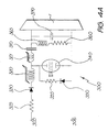
- Figure 4A illustrates an excitation circuit which may be used to provide excitation pulses to the laser discharge tube assembly illustrated in Figure 1A.
- excitation circuit 300 is a thyratron-switched pulse charging circuit consisting of a 0-9kV DC supply (not shown) connected to terminals 305, 306.
- the DC supply is connected to storage capacitor 310 (2-6 nF) via saturable inductor 320, magnetic assist 321, resistor 325 (100 ⁇ ) and diode 330 (Varo VC80X).
- Diode 350 and series resistor 355 (1 k ⁇ ) are provided to prevent the reverse voltages which arise from ringing in the discharge circuit from appearing across thyratron 340.
- Resistor 360 100 ⁇ wirewound
- inductor 365 tie one side of storage capacitor 310 to ground during the charging of storage capacitor 310.
- Peaking capacitor 370 (0.8-2nF) is connected across electrodes 50, 51 of laser discharge tube assembly 1 (see Figure 1A and Figure 2).
- discharge tube 10 When the laser is operated, the temperature of discharge tube 10 is brought to about 850°C by passing current through heating element 100. If it is desired to pre-condition discharge tube 10, at this stage a mixture of neon and hydrogen chloride (partial pressure of hydrogen chloride of about 13.3 kPa) is admitted from mixing chamber 240 (see Figure 3) into discharge tube 10 via gas inlet 95 and is allowed to flow slowly through discharge tube 10 and exit via gas outlet 90, for a period of about ten hours. At the end of this period, or if discharge tube has not been pre-conditioned, discharge tube 10 is evacuated by operating rotary pump 220 and, when a sufficiently low pressure has been reached, turbomolecular pump 210. Discharge tube 10 is then filled with a pure Ne buffer gas.
- a mixture of neon and hydrogen chloride partial pressure of hydrogen chloride of about 13.3 kPa
- Excitation circuit 300 operates as follows. After each discharge pulse the high voltage DC power supply applied to terminals 305, 306 resonantly charges storage capacitor 310 to nearly twice the supply voltage through resistor 325, diode 330 and saturable inductor 320. Saturable inductor 320 provides extended hold off ( ⁇ 20 ⁇ s) to thyratron 340 during its recovery stage after each pulse.
- Magnetic assist 321 Additional thyratron protection is provided by magnetic assist 321 to hold off the current flowing through thyratron 340 for several nanoseconds during the switching period in which thyratron 340 is going into conduction.
- Magnetic assist 321 is provided by including about twenty ferrite toroids on the line connecting the anode of thyratron 340 to storage capacitor 310, providing a saturable inductance in the storage capacitor - thyratron - peaking capacitor charge transfer loop.
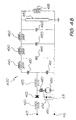
- FIG. 4B represents a magnetically assisted L-C inverter followed by three stage magnetic pulse compression.
- Circuit 400 illustrated in Figure 4B operates as follows:
- Storage capacitors 410 and 411 are resonantly charged (in parallel) to approximately twice the supply voltage (V 0 ) at terminals 415, 416 via charging inductor 420, charging diode 425 and tube bypass inductor 428 which is connected across the electrodes of metal vapour laser discharge tube 470.
- V 0 supply voltage
- thyratron 430 When thyratron 430 is switched, the voltage on storage capacitor 411 is reversed via ringing in the subcircuit comprising transfer inductor 435 and storage capacitor 411.
- the value of transfer inductor 435 is chosen so that the time taken for the voltage on storage capacitor 411 to swing from +2V 0 to -2V 0 is equal to the hold-off time of first saturable inductor 440.
- the voltage across the combination of storage capacitors 410, 411 reaches about 4V 0 .
- the charge on storage capacitors 410, 411 is transferred to capacitor 445, in a time that is shorter (by a factor called the compression ratio ) than the time taken to initially invert the voltage on storage capacitor 411.
- the compression ratio the time taken to initially invert the voltage on storage capacitor 411.
- second stage compressor 450 saturates, and the charge from capacitor 445 is transferred from capacitor 445 to capacitor 455 in a time again shorter by the compression of this stage, than capacitor 455 was charged.
- Circuit 400 incorporates two techniques for minimising this stress.
- Magnetic assist 480 delays zero-current crossing during grid-anode recovery until thyratron 430 has recovered.
- Snubber 490 (consisting of high-power resistor 491 and diode 492 in series) partially absorbs energy that is reflected from discharge tube 470.
- circuits incorporating pulse transformers to increase the voltage from a low voltage source to levels appropriate for laser excitation may be used.
- Circuits using different switching elements other than thyratrons (for example solid-state switches) may also be used, and capacitance transfer topologies can be used instead of L-C inverter circuits.
- Such circuits are well known for use with metal vapour lasers and their application with the metal vapour laser of the present invention lies well within the capability of persons of ordinary skill in the relevant art.
- metal vapour laser of the present invention are not dependent on the type of excitation used for the laser discharge tube.
- a copper vapour laser having a 25mm diameter by 1000mm long laser discharge tube was operated with a neon buffer gas flowing at ⁇ 3 atm.mL/min, including various added gases, at 17.5kHz pulse repetition rate unless otherwise stated, with 1.5nF of storage capacitance and 0.6nF of peaking capacitance.
- Figures 5A to 5C illustrate the effect of the added gases employed on the output power of the laser. It will be seen that in the example illustrated in Figure 5A the inclusion of chlorine and bromine resulted in a decrease in the output power over the range of concentrations tested, but the addition of hydrogen chloride and hydrogen bromide resulted in a substantial increase in output power over a range of concentrations, with an optimum at 1-2% hydrogen chloride or hydrogen bromide in the buffer gas by volume.
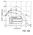
- Figure 5B illustrates the effect of added hydrogen in the buffer gas on the output power of the laser.
- various amounts by volume of HBr, HCl, 1:1 H 2 -Br 2 and 1:1 H 2 /Cl 2 were added to the buffer gas. It will be seen that under these conditions, the addition of a mixture of hydrogen and bromine enhanced the peak output power of the laser compared to the addition of the same amount of HBr, whereas the addition of a mixture of hydrogen and chlorine reduced the peak output power of the laser compared to the addition of the same amount of HCl.
- Figure 5C illustrates the effect of buffer gas flow rate on peak output power of the laser, with various amounts of HCl and HBr added to the neon buffer gas.
- the laser was operated at slow (approx. 4-5 atm.mL/min) or fast (approx. 60 atm.mL/min) flow rates.
- the performance of the laser was best when operating with added HBr at relatively fast buffer flow rate, whereas at more typical buffer flow gas rates of about 4 atm.mL/min, optimal performance is achieved when employing HCl/neon buffer gas mixtures.
- Figures 6A to 6C illustrate the spatial near-field profile of the laser beam under the conditions described above in this Example, with hydrogen chloride added to the buffer gas, when the concentration of hydrogen chloride was varied from 0% (Fig. 6A) to 1% by volume (Fig. 6B) and to 2% by volume (Fig.6C).
- Figure 7 provides a graph of the temporal evolution of the laser pulse
- Figures 8A and 8B plot the peak amplitude of the excitation current and voltage pulses, respectively, at a range of hydrogen chloride additive concentrations. It will be seen that particularly in the range of 1-2% by volume added HCl, the addition of hydrogen chloride to the buffer gas significantly modified the spatio-temporal evolution of the laser pulse and altered the peak amplitude of the excitation voltage and current pulses.
- the copper vapour laser used in these experiments was a 40mm x 1.5m long device (nominally a 55W device when operated at 4.5 kHz) employing a three stage magnetic pulse compression excitation circuit.
- the laser was operated at a pulse repetition frequency of 9 kHz at reduced input powers ( ⁇ 80% of optimum) so that potential overheating effects, due to the improved impedance matching resulting from some buffer gas additives, could be avoided.
- the buffer gas flow rates were 2-5 atm.mL/min.
- Table 1 shows the output power produced by the laser when operating with a pure neon buffer gas, a 2% H 2 additive, and a range of amounts of HBr with 1% H 2 buffer gas additive. All additive amounts are given in percentages by volume.
- Table 2 shows the output power when operating with a pure neon buffer gas, a 2% H 2 additive, and a range of amounts of HCl with 1 % H 2 buffer gas additive.
- a 25mm diameter copper vapour laser discharge tube was pre-conditioned at 850°C with the laser off by including 13 Pa to 101 kPa (typically about 13 kPa) partial pressures of HCl, HBr, Cl 2 and Br 2 in a neon buffer gas, typically at a partial pressure of from 1.3 kPa to 13 kPa, most typically at a partial pressure of about 5.3 kPa, for from 30 minutes to several hours.
- 13 Pa to 101 kPa typically about 13 kPa
- HCl, HBr, Cl 2 and Br 2 in a neon buffer gas typically at a partial pressure of from 1.3 kPa to 13 kPa, most typically at a partial pressure of about 5.3 kPa, for from 30 minutes to several hours.
- the laser was operated under the conditions described in Example 1, with the exception that a mixture of hydrogen-neon (about 13-260 Pa partial pressure of hydrogen) and pure neon were alternately flowed through the tube until the voltage/current characteristics of the laser resembled those shown in Figures 8A and 8B. Under these conditions, the power output of the laser increased from 10 to 30W for approximately 3kW input power and was very stable. It was found that the best results were obtained in this Example when the discharge tube was pre-conditioned with either HCI or Cl 2 .
- Table 3 shows the maximum total output power which achieved in a series of trials with a plane/plane resonator in a 25 mm diameter copper vapour laser of the invention having a hydrogen chloride/hydrogen mixture included in the buffer gas (about 13 Pa to 260 Pa partial pressure of each), together with the non-ASE high beam quality output powers produced from a 25 mm diameter copper vapour laser of the invention when employing on-axis unstable resonators.
- corresponding output power values obtained when the same laser is operated under the same conditions but without added hydrogen chloride pure neon buffer gas or neon-hydrogen buffer gas: about 13-260 Pa partial pressure of hydrogen
- Table 4 provides similar results for a 40 mm diameter copper vapour laser, which had been pre-conditioned with HCl as described in Example 2 prior to operation with a neon-hydrogen buffer gas mixture.
- the laser described in Example 1 was provided with about 25g of tantalum metal pieces between the cathode and the plasma tube, and was pre-conditioned for 3-24 hours with about 13kPa of HCl at a laser wall temperature of about 1000°C before being evacuated and operated with various buffer gases.
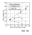
- Figure 9A shows the total output power of the laser operating with a plane/plane resonator with pure Ne, H 2 -Ne (2% hydrogen by volume) and HCl-H 2 -Ne (0.5% HCl and 1% H 2 by volume) buffer gas mixtures, over a range of pulse repetition frequencies (PRFs).
- This laser produced a maximum of ⁇ 20W when operated with a 2% H 2 -Ne buffer gas mixture at a PRF of 17 kHz.
- the output power of the laser operating with the H 2 -Ne buffer gas mixture decreased when the PRF was elevated above 17 kHz.
- Laser performance improved significantly when the H 2 -Ne buffer gas mixture was replaced with the H 2 -HCl-Ne mixture.
- the laser produced 32W at a PRF of 18 kHz. Furthermore, the H 2 -HCl-Ne buffer gas mixture permitted efficient PRF scaling of this device. At PRFs of 25 and 29 kHz the laser produced 40W and 51W respectively (compared to ⁇ 20W when employing conventional buffer gases).
- H 2 -neon buffer gas mixture the H 2 -neon buffer gas mixture
- HCl-H 2 -neon buffer gas mixture over a range of PRFs.
- the high beam quality (HBQ) output power extraction from this device was unaffected by the buffer gas composition when operated at low PRF ( ⁇ 4kHz).
- significant improvements in the HBQ output were observed when the laser was operated at elevated PRFs with either H 2 or H 2 -HCl added to the neon buffer gas.
- Added H 2 increased the HBQ output power of the laser by up to 3-4 times
- added H 2 -HCl increased the output power by up to 6-10 times, leading
- the laser described in Example 2 was provided with about 25g of tantalum metal pieces between the cathode and the plasma tube, and was pre-conditioned for 3-24 hours with about 13kPa of HCl at a laser wall temperature of about 1000°C before being evacuated and operated with various buffer gases.
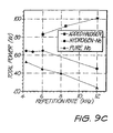
- Figure 9C shows the total output power of the laser operating with a plane/plane resonator with pure Ne, H 2 -Ne (1% hydrogen by volume) and HCl-H 2 -Ne (0.5% HCl and 1% H 2 by volume) buffer gas mixtures, over a range of PRFs.
- the laser produced a maximum of 53W at a PRF of 4.3 kHz when operated with pure Ne buffer gas, and a maximum of 65W when operated with a 1% H 2 -Ne mixture.
- These output powers are comparable to those normally produced by copper vapour laser of twice the volume (ie. diameter >60cm and lengths >2m).
- the specific output powers of the 25mm and 40mm diameter lasers described in Examples 4 and 5, namely 104mW/cm 3 and 54mW/cm 3 respectively, are the highest yet achieved from copper vapour lasers of this size and are comparable to those obtained from copper HyBrID ("Hydrogen Bromide In Discharge") lasers of similar active volumes.
- the improved output power extraction of copper vapour lasers operating at elevated PRFs with H 2 -HCl-Ne buffer gas mixtures results from both modified temporal and spatial gain characteristics.
- the duration of a copper vapour laser output pulse is significantly shortened (for the same peak power) as the PRF is elevated, leading to a reduction in total output power.
- the pulse duration of the 25mm diameter copper vapour laser operating with a pure Ne buffer gas was only ⁇ 30ns (compared to 55ns at a PRF of 4.5 kHz) or only two round-trips through the resonator. This characteristic limits the usefulness of copper vapour lasers when required for high repetition rate, high beam quality applications.
- a hydrogen buffer gas additive extends the efficient PRF scaling capability of the 25mm and 40mm diameter copper vapour lasers to 17 and 6 kHz respectively.
- the H 2 -HCl additive increases the pulse duration by a greater amount than added H 2 . Indeed, at a PRF of 17 kHz the pulse duration of the 25mm diameter copper vapour laser was increased from 30ns to ⁇ 60ns, consistent with radiation undergoing an additional two round-trips through the gain region.
- the output power of the 25mm and 40mm diameter copper vapour lasers with included tantalum metal and H 2 -HCl-Ne buffer gas mixture scaled linearly up to the maximum PRFs (ie. 30 and 12 kHz respectively) available with the existing laser excitation circuits.
- the modified spatial characteristics also contribute to the improved PRF scaling capability of copper vapour lasers operating with H 2 -HCl-Ne buffer gas.
- the radial intensity profile of copper vapour lasers operating with pure Ne approximates a "top-hat" structure.
- the intensity profile becomes increasingly annular.
- PRFs >20kHz the 25mm diameter copper vapour laser output is visibly restricted to a ring near the tube wall.
- PRFs of ⁇ 20kHz the intensity profile of the 25mm diameter copper vapour laser operating with H 2 -Ne buffer gases is still relatively annular.
- the same copper vapour laser operating with H 2 -HCl added to the neon buffer gas has an axially peaked intensity profile at PRFs up to and beyond 20 kHz.
- Example 2 Enhanced performance of the 40mm diameter laser described in Example 2 has also been observed using metal halide as the sole source of halogen.
- the laser yielded about 75W of output power when operated with a neon buffer gas containing 2% by volume of hydrogen, without pre-conditioning, but with a small, amount of TaCl 5 powder placed in a tray underneath the cathode, using either copper or stainless steel electrodes.
- Similar increases in output power were also observed when the halogen source comprised a piece of insulator impregnated with trace amounts of TaCl 5 powder, or a section of glass matting impregnated with trace amounts of TaCl 5 powder.
- the output power of the laser increased still further to 92W when the laser was operated under these same conditions but with electrodes manufactured from tantalum.
- output powers achievable by a metal vapour laser of the present invention represent a substantial increase over those achievable by conventional metal vapour lasers, without sacrifice in beam quality or other desirable laser characteristics.
Landscapes
- Physics & Mathematics (AREA)
- Electromagnetism (AREA)
- Engineering & Computer Science (AREA)
- Plasma & Fusion (AREA)
- Optics & Photonics (AREA)
- Lasers (AREA)
Claims (56)
- Elementarer Metalldampf-Laser (1) umfassend eine Entladungsröhre (10), die ein Puffergas darin aufweist und bei einer hohen Temperatur betrieben wird, so dass der Dampfdruck des elementaren Metalls (110) durch thermische Verdampfung des Metalls (110) eingestellt wird und ausreichend hoch ist, um die Erzeugung von Laserlicht durch den Laser bei der hohen Temperatur zu ermöglichen, wobei das Puffergas eine die Laserausgangsleistung erhöhende Substanz in einer Menge enthält, die ausreicht, um die Ausgangsleistung des Lasers wesentlich zu erhöhen, dadurch gekennzeichnet, dass die die Laserausgangsleistung erhöhende Substanz eine Spezies ist, die ein oder mehr Atome, ausgewählt aus Fluor, Chlor, Brom und lod, umfasst.
- Elementarer Metalldampf-Laser nach Anspruch 1, außerdem umfassend Mittel (240), die mit der Entladungsröhre funktionell verbunden sind, um dem Puffergas ein Additiv zuzugeben, welches die Konzentration der die Laserausgangsleistung erhöhenden Substanz in dem Puffergas regeln kann.
- Elementarer Metalldampf-Laser nach Anspruch 1 oder Anspruch 2, wobei die die Laserausgangsleistung erhöhende Substanz ausgewählt wird aus der Gruppe bestehend aus einem Gemisch aus Wasserstoff und Fluor, einem Gemisch aus Wasserstoff und Chlor, einem Gemisch aus Wasserstoff und Brom, einem Gemisch aus Wasserstoff und lod, HF, HCI, HBr und HI.
- Elementarer Metalldampf-Laser nach Anspruch 2, wobei das Additiv ausgewählt wird aus der Gruppe bestehend aus H2, D2, T2, HD, HT, DT, H2O und D2O.
- Elementarer Metalldampf-Laser nach Anspruch 4, wobei das Additiv H2 oder H2O ist und die die Laserausgangsleistung erhöhende Substanz ausgewählt wird aus der Gruppe bestehend aus Chlor, Brom, HCI und HBr.
- Elementarer Metalldampf-Laser nach Anspruch 5, wobei das Additiv H2 ist und die die Laserausgangsleistung erhöhende Substanz HCI ist.
- Elementarer Metalldampf-Laser nach Anspruch 1 oder Anspruch 2, wobei die die Laserausgangsleistung erhöhende Substanz unter den Betriebsbedingungen des Lasers aus einem in dem Laser enthaltenen Metallhalogenid erhalten wird.
- Elementarer Metalldampf-Laser nach Anspruch 7, wobei das Metallhalogenid ausgewählt wird aus der Gruppe bestehend aus AuCl3, FeCl3, HgBr2, HgCl2, HgF2, NbBr5, NbF5, NbCl5, OsF5, TiCl4, TiCl3, TiBr4, ZrCl4, ZrBr4, MoF5, MoCl5, NiCl2, CoCl2, WBr5, WCl5, WCl6, AlCl3, ReCl5, ReCl6, ReBr4, PbBr2, PbCl2, TaCl5, TaF5, TaBr5, Tal5, SnBr4, SnCl2, SnCl4, SnF2, SnF4, VCl4, VCl3, VCl2, ZnBr2, ZnBr4 und Gemischen aus zwei oder mehr davon.
- Elementarer Metalldampf-Laser nach Anspruch 7, wobei das Metallhalogenid ein Kupfer(I)-halogenid ist, das aus in dem Laser enthaltenem Kupfer und Kupfer(II)-halogenid erhalten wird.
- Elementarer Metalldampf-Laser nach Anspruch 8, wobei das Metallhalogenid ein Metallchlorid ist.
- Elementarer Metalldampf-Laser nach Anspruch 10, wobei das Metallhalogenid TaCl5 und/oder ZrCl4 ist.
- Elementarer Metalldampf-Laser nach Anspruch 5 oder Anspruch 11, welcher ein Kupferdampf-Laser ist, wobei die hohe Temperatur 1400-1700°C beträgt.
- Elementarer Metalldampf-Laser nach Anspruch 7, wobei das Metallhalogenid in der Entladungsröhre durch die Reaktion von einem Metall und einem halogenhaitigen Reagenz erzeugt wird.
- Elementarer Metalldampf-Laser nach Anspruch 13, wobei das Metallhalogenid in der Entladungsröhre durch die Reaktion von Kupfer und einem halogenhaltigen Reagenz erzeugt wird.
- Elementarer Metalldampf-Laser nach Anspruch 13, wobei das halogenhaltige Reagenz ein festes halogenhaltiges Reagenz ist.
- Elementarer Metalldampf-Laser nach einem der vorangehenden Ansprüche, wobei der Metalldampf ein Kupferdampf ist.
- Elementarer Metalldampf-Laser nach einem der Ansprüche 1 bis 11, 13, 14 oder 15, wobei der Metalldampf ein Golddampf ist.
- Elementarer Metalldampf-Laser nach Anspruch 1, dadurch gekennzeichnet, dass der Laser außerdem eine Menge eines zweiten Metalls (130) oder eines Salzes davon umfasst, wobei das zweite Metall (130) von dem ersten elementaren Metall (110) verschieden ist, wobei das zweite Metall (130) oder Salz mit einem gasförmigen halogenhaltigen Reagenz unter Bildung eines Halogenids des zweiten Metalls reagieren kann, wobei die die Laserausgangsleistung erhöhende Substanz eine Spezies ist, die aus dem Halogenid des zweiten Metalls unter den Betriebsbedingungen des Lasers erhalten wird.
- Elementarer Metalldampf-Laser nach Anspruch 18, wobei das zweite Metall (130) ausgewählt wird aus der Gruppe bestehend aus Tantal, Zirconium, Palladium, Nickel, Niob, Platin, Kupfer, Aluminium, Titan, Molybdän, Wolfram, Blei, Rhenium und Zinn.
- Elementarer Metalldampf-Laser nach Anspruch 18, wobei das zweite Metall (130) Tantal oder Zirconium ist.
- Elementarer Metalldampf-Laser nach einem der Ansprüche 18 bis 20, wobei das gasförmige halogenhaltige Reagenz ein Halogen oder einen Halogenwasserstoff umfasst.
- Elementarer Metalldampf-Laser nach Anspruch 21, wobei das gasförmige halogenhaltige Reagenz ausgewählt wird aus der Gruppe bestehend aus HCI, HBr und Gemischen davon.
- Elementarer Metalldampf-Laser nach einem der Ansprüche 18 bis 20, wobei das zweite Metall (130) in einem innigen Gemisch mit einem festen halogenhaltigen Reagenz vorliegt, das mit dem zweiten Metall unter den Betriebsbedingungen des Lasers unter Bildung des Metallhalogenids reagieren kann.
- Elementarer Metalldampf-Laser nach einem der Ansprüche 18 bis 23, außerdem umfassend eine Menge einer Substanz, ausgewählt aus der Gruppe bestehend aus einem dritten Metall und einem Metallhalogenid, wobei das dritte Metall von dem elementaren Metall und dem zweiten Metall verschieden ist.
- Elementarer Metalldampf-Laser nach Anspruch 24, wobei das dritte Metall ausgewählt wird aus der Gruppe bestehend aus Au, Fe, Hg, Nb, Os, Ti, Zr, Mo, Ni, Co, W, AI, Re, Pb, Ta, Sn, V und Zn.
- Elementarer Metalldampf-Laser nach einem der Ansprüche 18 bis 25, wobei der Laser ein Puffergas enthält, das ein Additiv umfasst, welches Wasserstoff ist.
- Elementarer Metalldampf-Laser nach einem der Ansprüche 18 bis 25, wobei der Laser außerdem eine Menge eines Metallhydrids umfasst, das bei einer Betriebstemperatur des Lasers unter Bildung von Wasserstoffatomen dissoziieren kann.
- Elementarer Metalldampf-Laser nach einem der Ansprüche 18 bis 25, wobei das elementare Metall Kupfer ist.
- Elementarer Metalldampf-Laser nach einem der Ansprüche 18 bis 25, wobei das elementare Metall Gold ist.
- Elementarer Kupferdampf-Laser nach Anspruch 16, außerdem umfassend eine Menge an Tantalmetall oder Zirconiummetall, wobei der Laser ein Puffergas enthält, welches ein Gemisch aus HCI oder HBr mit einem Inertgas und Wasserstoff ist, wobei das Tantalmetall oder Zirconiummetall sich in einem Bereich der Entladungsröhre befindet, wo es mit dem Puffergas in Kontakt gebracht wird.
- Verfahren zum Betreiben eines elementaren Metalldampf-Lasers (1) umfassend eine Entladungsröhre (10), die ein Puffergas darin aufweist und bei einer solchen Temperatur betrieben wird, dass der Dampfdruck des elementaren Metalls (110) durch thermische Verdampfung des Metalls (110) eingestellt wird, wobei der Metalldampfdruck ausreichend hoch ist, um die Erzeugung von Laserlicht durch den Laser bei dieser Temperatur zu ermöglichen, umfassend das Vorvermischen einer die Laserausgangsleistung erhöhenden Substanz mit dem Puffergas und/oder das Erzeugen einer die Laserausgangsleistung erhöhenden Substanz in der Entladungsröhre, wobei die die Laserausgangsleistung erhöhende Substanz in der Entladungsröhre unter den Betriebsbedingungen des Lasers in einer Menge vorhanden ist, die ausreicht, um die Ausgangsleistung des Lasers wesentlich zu erhöhen, dadurch gekennzeichnet, dass die die Laserausgangsleistung erhöhende Substanz eine Spezies ist, die ein oder mehr Atome, ausgewählt aus Fluor, Chlor, Brom und lod, umfasst.
- Verfahren nach Anspruch 31, umfassend den Schritt des Einstellens der Konzentration der die Laserausgangsleistung erhöhenden Substanz durch Zugeben eines Additivs zu dem Puffergas, welches die Konzentration der die Laserausgangsleistung erhöhenden Substanz in dem Puffergas regeln kann.
- Verfahren nach Anspruch 31 oder Anspruch 32, wobei die die Laserausgangsleistung erhöhende Substanz ausgewählt wird aus der Gruppe bestehend aus einem Gemisch aus Wasserstoff und Fluor, einem Gemisch aus Wasserstoff und Chlor, einem Gemisch aus Wasserstoff und Brom, einem Gemisch aus Wasserstoff und lod, HF, HCI, HBr und HI.
- Verfahren nach Anspruch 32, wobei das Additiv ausgewählt wird aus der Gruppe bestehend aus H2, D2, T2, HD, HT, DT, H2O und D2O.
- Verfahren nach Anspruch 34, wobei das Additiv H2 oder H2O ist und die die Laserausgangsleistung erhöhende Substanz ausgewählt wird aus der Gruppe bestehend aus Chlor, Brom, HCI und HBr.
- Verfahren nach Anspruch 35, wobei das Additiv H2 ist und die die Laserausgangsleistung erhöhende Substanz HCI ist.
- Verfahren nach Anspruch 31 oder Anspruch 34, wobei die die Laserausgangsleistung erhöhende Substanz in der Entladungsröhre aus einem in dem Laser enthaltenen Metallhalogenid erzeugt wird.
- Verfahren nach Anspruch 37, wobei das Metallhalogenid ausgewählt wird aus der Gruppe bestehend aus AuCl3, FeCl3, HgBr2, HgCl2, HgF2, NbBr5, NbF5, NbCl5, OsF5, TiCl4, TiCl3, TiBr4, ZrCl4, ZrBr4, MoF5, MoCl5, NiCl2, CoCl2, WBr5, WCl5, WCl6, AlCl3, ReCl5, ReCl6, ReBr4, PbBr2, PbCl2, TaCl5. TaF5, TaBr5, Tal5, SnBr4, SnCl2, SnCl4, SnF2, SnF4, VCl4, VCl3, VCl2, ZnBr2, ZnBr4 und Gemischen aus zwei oder mehr davon.
- Verfahren nach Anspruch 37, wobei das Metallhalogenid ein Kupfer(I)-halogenid ist, das aus in dem Laser enthaltenem Kupfer und Kupfer(11)-halogenid erhalten wird.
- Verfahren nach Anspruch 38, wobei das Metallhalogenid ein Metallchlorid ist.
- Verfahren nach Anspruch 40, wobei das Metallhalogenid TaCl5 und/oder ZrCl4 ist.
- Verfahren nach Anspruch 32 oder Anspruch 40, wobei der Laser ein Kupferdampf-Laser ist und die Temperatur 1400-1700°C beträgt.
- Verfahren nach Anspruch 37, wobei das Metallhalogenid in der Entladungsröhre durch die Reaktion von einem Metall und einem halogenhaltigen Reagenz erzeugt wird.
- Verfahren nach Anspruch 43, wobei das halogenhaltige Reagenz ein festes halogenhaltiges Reagenz ist.
- Verfahren nach Anspruch 32, wobei die Konzentration des Additivs festliegt und die Konzentration der die Laserausgangsleistung erhöhenden Substanz durch Variieren einer Konzentration einer Vorstufe der die Laserausgangsleistung erhöhenden Substanz variiert wird.
- Verfahren nach Anspruch 31 oder 32, wobei die die Laserausgangsleistung erhöhende Substanz in der Entladungsröhre erzeugt wird, außerdem umfassend die Schritte:Vorkonditionieren des Lasers durch Durchleiten eines gasförmigen halogenhaitigen Reagenzes durch die Entladungsröhre bei einer Temperatur, die niedriger ist als die hohe Temperatur, während eines Zeitraums und unter Bedingungen, die dafür ausreichen, dass die die Laserausgangsleistung erhöhende Substanz oder eine Vorstufe der die Laserausgangsleistung erhöhenden Substanz gebildet wird, oder dass die die Laserausgangsleistung erhöhende Substanz auf einer Oberfläche der Entladungsröhre adsorbiert oder absorbiert wird, wobei das Reagenz mit der Oberfläche der Entladungsröhre reagieren oder davon adsorbiert oder absorbiert werden kann;Beenden des Durchleitens des gasförmigen halogenhaltigen Reagenzes; undErhöhen der Temperatur der Entladungsröhre auf die hohe Temperatur.
- Verfahren nach Anspruch 31, umfassend:Bereitstellen einer Menge des elementaren Metalls (110) und einer Menge eines zweiten Metalls (130) oder eines Salzes davon in dem Laser, wobei das zweite Metall (130) von dem ersten elementaren Metall (110) verschieden ist und das zweite Metall (130) oder Salz mit einem gasförmigen halogenhaltigen Reagenz unter Bildung eines Halogenids des zweiten Metalles reagieren kann, wobei die die Laserausgangsleistung erhöhende Substanz eine Spezies ist, die unter den Betriebsbedingungen des Lasers aus dem Halogenid des zweiten Metalls (130) erhalten wird;Vorkonditionieren des Lasers durch Inkontaktbringen eines gasförmigen halogenhaitigen Reagenzes mit dem zweiten Metall in der Entladungsröhre bei einer Temperatur, die niedriger ist als die hohe Temperatur, während eines Zeitraums und unter Bedingungen, die dafür ausreichen, dass ein Halogenid des zweiten Metalls (130) gebildet wird;Erhöhen der Temperatur der Entladungsröhre auf die hohe Temperatur;Leiten des Puffergases durch die Entladungsröhre; undErzeugen einer Entladung in der Entladungsröhre und Erzeugen von Laserlicht aus dem Laser.
- Verfahren nach Anspruch 47, wobei das zweite Metall (130) ausgewählt wird aus der Gruppe bestehend aus Tantal, Zirconium, Palladium, Nickel, Niob, Platin, Kupfer, Aluminium, Titan, Molybdän, Wolfram, Blei, Rhenium und Zinn.
- Verfahren nach Anspruch 48, wobei das zweite Metall (130) Tantal oder Zirconium ist.
- Verfahren nach Anspruch 47, außerdem umfassend das Bereitstellen einer Menge einer Substanz in dem Laser, ausgewählt aus der Gruppe bestehend aus einem dritten Metall und einem Metallhalogenid, wobei das dritte Metall von dem elementaren Metall und dem zweiten Metall verschieden ist.
- Verfahren nach Anspruch 47, wobei das gasförmige halogenhaltige Reagenz ein Halogen oder einen Halogenwasserstoff umfasst.
- Verfahren nach Anspruch 51, wobei das gasförmige halogenhaltige Reagenz ausgewählt wird aus der Gruppe bestehend aus HCI, HBr und Gemischen davon.
- Verfahren nach einem der Ansprüche 47 bis 50, wobei das Puffergas Wasserstoff umfasst.
- Verfahren nach Anspruch 53, wobei das Puffergas außerdem ein Halogen oder einen Halogenwasserstoff umfasst.
- Verfahren nach einem der Ansprüche 47 bis 50, wobei das elementare Metall (110) Kupfer ist.
- Verfahren nach einem der Ansprüche 47 bis 50, wobei das elementare Metall (110) Gold ist.
Applications Claiming Priority (4)
| Application Number | Priority Date | Filing Date | Title |
|---|---|---|---|
| AUPN8135/96 | 1996-02-16 | ||
| AUPN8135A AUPN813596A0 (en) | 1996-02-16 | 1996-02-16 | Metal vapour laser |
| AUPN813596 | 1996-02-16 | ||
| PCT/AU1997/000083 WO1997030496A1 (en) | 1996-02-16 | 1997-02-17 | Metal vapour laser |
Publications (3)
| Publication Number | Publication Date |
|---|---|
| EP0880811A1 EP0880811A1 (de) | 1998-12-02 |
| EP0880811A4 EP0880811A4 (de) | 1999-03-03 |
| EP0880811B1 true EP0880811B1 (de) | 2003-01-08 |
Family
ID=3792449
Family Applications (1)
| Application Number | Title | Priority Date | Filing Date |
|---|---|---|---|
| EP97904296A Expired - Lifetime EP0880811B1 (de) | 1996-02-16 | 1997-02-17 | Metalldampflaser |
Country Status (6)
| Country | Link |
|---|---|
| US (1) | US6175583B1 (de) |
| EP (1) | EP0880811B1 (de) |
| AU (1) | AUPN813596A0 (de) |
| CA (1) | CA2245892C (de) |
| DE (1) | DE69718293D1 (de) |
| WO (1) | WO1997030496A1 (de) |
Families Citing this family (10)
| Publication number | Priority date | Publication date | Assignee | Title |
|---|---|---|---|---|
| JP3880285B2 (ja) * | 1999-03-19 | 2007-02-14 | サイマー, インコーポレイテッド | ガス放電レーザに関する長パルスパルスパワーシステム |
| RU2170999C1 (ru) * | 1999-12-30 | 2001-07-20 | Научно-исследовательский институт газоразрядных приборов | Лазер на парах химических элементов |
| RU2229188C1 (ru) * | 2002-12-30 | 2004-05-20 | Томский политехнический университет | Способ уменьшения предымпульсной концентрации электронов в активной среде лазера на парах галогенида металла и активный элемент лазера на парах галогенида металла |
| US20050272610A1 (en) * | 2004-05-24 | 2005-12-08 | Vanderbilt University | Apparatus and methods of tissue ablation using Sr vapor laser system |
| FR2952223B1 (fr) * | 2009-11-03 | 2018-09-21 | Schneider Electric Energy France | Utilisation de materiaux composites specifiques en tant que materiaux d'extinction d'arc electrique dans des appareils electriques |
| US20170133813A1 (en) * | 2015-11-09 | 2017-05-11 | Transformation Point Technologies, LLC | Lasing gas recycling |
| CN106785880B (zh) * | 2016-12-06 | 2020-08-28 | 西南技术物理研究所 | 碱金属蒸气最大粒子数密度限定密闭池及其制作方法 |
| US11459864B1 (en) * | 2021-05-13 | 2022-10-04 | Saudi Arabian Oil Company | High power laser in-situ heating and steam generation tool and methods |
| CN114243435B (zh) * | 2021-12-22 | 2023-06-02 | 电子科技大学 | 一种等离子体光子晶体激波器 |
| CN115483596B (zh) * | 2022-10-24 | 2023-10-20 | 中国航天三江集团有限公司 | 基于碱金属蒸气和缓冲气体填充的激光器及其应用 |
Family Cites Families (16)
| Publication number | Priority date | Publication date | Assignee | Title |
|---|---|---|---|---|
| US3934211A (en) * | 1973-03-09 | 1976-01-20 | Westinghouse Electric Corporation | Metal halide vapor laser |
| US3936772A (en) * | 1973-03-09 | 1976-02-03 | Westinghouse Electric Corporation | High flow metal halide vapor laser |
| US3831107A (en) * | 1973-03-21 | 1974-08-20 | Gen Electric | Cesium quenched copper laser |
| DE2951723C2 (de) * | 1979-12-20 | 1983-09-08 | Bodo Auschwitz | Metalldampflaser mit Gaszusätzen zur Verbesserung der Emissionseigenschaften |
| AU4206585A (en) * | 1984-05-04 | 1985-11-07 | Quentron Optics Pty. Ltd. | Improving efficiency of metal vapour laser |
| JP2659730B2 (ja) * | 1987-12-08 | 1997-09-30 | 株式会社東芝 | 金属蒸気レーザ装置 |
| GB8812276D0 (en) * | 1988-05-24 | 1988-06-29 | English Electric Valve Co Ltd | Laser apparatus |
| US5077749A (en) * | 1989-07-10 | 1991-12-31 | Kabushiki Kaisha Toshiba | Laser apparatus |
| GB9024733D0 (en) * | 1990-11-14 | 1991-01-02 | Eev Ltd | Laser apparatus |
| GB2262184B (en) * | 1991-11-07 | 1995-06-07 | Mitsubishi Electric Corp | Pulse laser apparatus |
| GB2269266B (en) * | 1992-07-30 | 1995-11-22 | Eev Ltd | Metal vapour laser apparatus |
| GB2274541B (en) * | 1993-01-20 | 1996-03-27 | Eev Ltd | Laser arrangements |
| JPH0758383A (ja) * | 1993-08-16 | 1995-03-03 | Japan Atom Energy Res Inst | 低温作動型金属蒸気レーザー |
| JP2829479B2 (ja) * | 1993-08-18 | 1998-11-25 | 株式会社中央製作所 | 金属蒸気レーザー |
| US5504770A (en) * | 1993-12-27 | 1996-04-02 | The United States Of America As Represented By The Secretary Of The Navy | Liquid metal confinement cylinder for optical discharge devices |
| FR2743204B1 (fr) * | 1996-01-03 | 1998-02-13 | Commissariat Energie Atomique | Dispositif laser a vapeur metallique |
-
1996
- 1996-02-16 AU AUPN8135A patent/AUPN813596A0/en not_active Abandoned
-
1997
- 1997-02-17 EP EP97904296A patent/EP0880811B1/de not_active Expired - Lifetime
- 1997-02-17 WO PCT/AU1997/000083 patent/WO1997030496A1/en not_active Ceased
- 1997-02-17 CA CA002245892A patent/CA2245892C/en not_active Expired - Fee Related
- 1997-02-17 US US09/125,209 patent/US6175583B1/en not_active Expired - Fee Related
- 1997-02-17 DE DE69718293T patent/DE69718293D1/de not_active Expired - Lifetime
Also Published As
| Publication number | Publication date |
|---|---|
| EP0880811A4 (de) | 1999-03-03 |
| US6175583B1 (en) | 2001-01-16 |
| DE69718293D1 (de) | 2003-02-13 |
| WO1997030496A1 (en) | 1997-08-21 |
| AUPN813596A0 (en) | 1996-03-07 |
| EP0880811A1 (de) | 1998-12-02 |
| CA2245892C (en) | 2005-04-05 |
| CA2245892A1 (en) | 1997-08-21 |
Similar Documents
| Publication | Publication Date | Title |
|---|---|---|
| Jones et al. | A high-efficiency 200 W average power copper HyBrID laser | |
| US6175583B1 (en) | Metal vapour laser | |
| Sze | Rare-gas halide avalanche discharge lasers | |
| Borisov et al. | High-power, highly stable KrF laser with a pulse repetition rate | |
| Livingstone et al. | Characteristics of a copper bromide laser with flowing Ne-HBr buffer gas | |
| Budick et al. | Light sources for double resonance and level crossing spectroscopy | |
| US4301425A (en) | XeCl Avalanche discharge laser employing Ar as a diluent | |
| CA2068150A1 (en) | Gas probe starter for an electrodeless high intensity discharge lamp | |
| Bhadani et al. | Efficient helium‐free multi‐joule TE‐CO2 laser using spiker‐sustainer excitation | |
| Jones et al. | A copper HyBrID laser of 120 W average output power and 2.2% efficiency | |
| Zhupikov et al. | Excimer ArF laser with an output energy of 0.5 J and He buffer gas | |
| Velikanov et al. | Solid-state laser-pumped high-power electric-discharge HF laser | |
| Levatter et al. | Electron‐beam‐controlled discharge XeCl excimer laser | |
| Rutt | A high-energy hydrogen bromide laser | |
| Vagin et al. | A pulsed oxygen—iodine chemical laser excited by a longitudinal electric discharge | |
| Frank et al. | Do gas-filled switches still have a future? | |
| US3614642A (en) | Gas laser | |
| Mace | Excimer laser technology | |
| Zhupikov et al. | Excimer KrF laser with He buffer gas, 0.8 J energy, and 2% efficiency | |
| Schoenbach et al. | Diffuse discharge opening switches | |
| Kozlov et al. | Energy parameters and resource of high-power pulse-periodical sealed-off TEA-CO2 lasers | |
| Raffo et al. | Pulsed chemical HF laser using graphite continuous electrodes for transverse discharge stabilization | |
| Hentschel et al. | Repetition-rate scaling of a rectangular bore discharge-excited Sr+ recombination laser | |
| Huber | Wideband comet camera lens design | |
| WO2003023914A1 (en) | Low-pressure axial direction excitation type f2 laser oscillator |
Legal Events
| Date | Code | Title | Description |
|---|---|---|---|
| PUAI | Public reference made under article 153(3) epc to a published international application that has entered the european phase |
Free format text: ORIGINAL CODE: 0009012 |
|
| 17P | Request for examination filed |
Effective date: 19980915 |
|
| AK | Designated contracting states |
Kind code of ref document: A1 Designated state(s): DE FR GB IT |
|
| A4 | Supplementary search report drawn up and despatched | ||
| AK | Designated contracting states |
Kind code of ref document: A4 Designated state(s): DE FR GB IT |
|
| RHK1 | Main classification (correction) |
Ipc: H01S 3/03 |
|
| 17Q | First examination report despatched |
Effective date: 20000524 |
|
| GRAG | Despatch of communication of intention to grant |
Free format text: ORIGINAL CODE: EPIDOS AGRA |
|
| GRAG | Despatch of communication of intention to grant |
Free format text: ORIGINAL CODE: EPIDOS AGRA |
|
| GRAH | Despatch of communication of intention to grant a patent |
Free format text: ORIGINAL CODE: EPIDOS IGRA |
|
| GRAH | Despatch of communication of intention to grant a patent |
Free format text: ORIGINAL CODE: EPIDOS IGRA |
|
| GRAA | (expected) grant |
Free format text: ORIGINAL CODE: 0009210 |
|
| AK | Designated contracting states |
Kind code of ref document: B1 Designated state(s): DE FR GB IT |
|
| PG25 | Lapsed in a contracting state [announced via postgrant information from national office to epo] |
Ref country code: IT Free format text: LAPSE BECAUSE OF FAILURE TO SUBMIT A TRANSLATION OF THE DESCRIPTION OR TO PAY THE FEE WITHIN THE PRESCRIBED TIME-LIMIT;WARNING: LAPSES OF ITALIAN PATENTS WITH EFFECTIVE DATE BEFORE 2007 MAY HAVE OCCURRED AT ANY TIME BEFORE 2007. THE CORRECT EFFECTIVE DATE MAY BE DIFFERENT FROM THE ONE RECORDED. Effective date: 20030108 Ref country code: FR Free format text: LAPSE BECAUSE OF FAILURE TO SUBMIT A TRANSLATION OF THE DESCRIPTION OR TO PAY THE FEE WITHIN THE PRESCRIBED TIME-LIMIT Effective date: 20030108 |
|
| REG | Reference to a national code |
Ref country code: GB Ref legal event code: FG4D |
|
| REF | Corresponds to: |
Ref document number: 69718293 Country of ref document: DE Date of ref document: 20030213 Kind code of ref document: P |
|
| PG25 | Lapsed in a contracting state [announced via postgrant information from national office to epo] |
Ref country code: DE Free format text: LAPSE BECAUSE OF FAILURE TO SUBMIT A TRANSLATION OF THE DESCRIPTION OR TO PAY THE FEE WITHIN THE PRESCRIBED TIME-LIMIT Effective date: 20030409 |
|
| PLBE | No opposition filed within time limit |
Free format text: ORIGINAL CODE: 0009261 |
|
| STAA | Information on the status of an ep patent application or granted ep patent |
Free format text: STATUS: NO OPPOSITION FILED WITHIN TIME LIMIT |
|
| EN | Fr: translation not filed | ||
| 26N | No opposition filed |
Effective date: 20031009 |
|
| PGFP | Annual fee paid to national office [announced via postgrant information from national office to epo] |
Ref country code: GB Payment date: 20090211 Year of fee payment: 13 |
|
| GBPC | Gb: european patent ceased through non-payment of renewal fee |
Effective date: 20100217 |
|
| PG25 | Lapsed in a contracting state [announced via postgrant information from national office to epo] |
Ref country code: GB Free format text: LAPSE BECAUSE OF NON-PAYMENT OF DUE FEES Effective date: 20100217 |