EP0879896B1 - Apparatus and process for refining molten steel in the production of ultra-low carbon steel - Google Patents
Apparatus and process for refining molten steel in the production of ultra-low carbon steel Download PDFInfo
- Publication number
- EP0879896B1 EP0879896B1 EP96944131A EP96944131A EP0879896B1 EP 0879896 B1 EP0879896 B1 EP 0879896B1 EP 96944131 A EP96944131 A EP 96944131A EP 96944131 A EP96944131 A EP 96944131A EP 0879896 B1 EP0879896 B1 EP 0879896B1
- Authority
- EP
- European Patent Office
- Prior art keywords
- gas
- molten steel
- vessel
- oxygen
- lance
- Prior art date
- Legal status (The legal status is an assumption and is not a legal conclusion. Google has not performed a legal analysis and makes no representation as to the accuracy of the status listed.)
- Expired - Lifetime
Links
Images





Classifications
-
- C—CHEMISTRY; METALLURGY
- C21—METALLURGY OF IRON
- C21C—PROCESSING OF PIG-IRON, e.g. REFINING, MANUFACTURE OF WROUGHT-IRON OR STEEL; TREATMENT IN MOLTEN STATE OF FERROUS ALLOYS
- C21C7/00—Treating molten ferrous alloys, e.g. steel, not covered by groups C21C1/00 - C21C5/00
-
- C—CHEMISTRY; METALLURGY
- C21—METALLURGY OF IRON
- C21C—PROCESSING OF PIG-IRON, e.g. REFINING, MANUFACTURE OF WROUGHT-IRON OR STEEL; TREATMENT IN MOLTEN STATE OF FERROUS ALLOYS
- C21C7/00—Treating molten ferrous alloys, e.g. steel, not covered by groups C21C1/00 - C21C5/00
- C21C7/10—Handling in a vacuum
Definitions
- the present invention relates to an apparatus for refining molten steel in a secondary refining process to manufacture ultra low carbon steel and a method for refining molten steel by utilizing the apparatus.
- an RH vacuum degassing apparatus (to be called “RH” below) of FIG. 1 is used.
- RH vacuum degassing apparatus
- molten steel which is tapped from a converter (not shown in the drawings) without killing during tapping arrives at the RH, firstly argon (Ar) gas is injected from a circulation gas supplying device 130, and at the saine time, a snorkel 120 is dipped into a molten steel M which is contained within a ladle 140. Further at the same time, a vacuum pump 125 is activated to reduce the internal pressure of a vessel 110 to several Torr or several scores of Torr.
- Ar argon
- Japanese Patent Application Laid-open No. Sho-52-88215 and Sho-52-89513 disclose molten steel refining apparatuses for manufacturing ultra low carbon steel. These apparatuses are constituted as follows. That is, as shown in FIG. 2, a lance nozzle 150 is installed on the ceiling of the RH vessel 110, for injecting gaseous oxygen so as to shorten the decarburization period when producing ultra low carbon steel. Thus during the decarburization of molten steel, gaseous oxygen is injected through the lance nozzle 150 onto the surface of molten steel within the vessel at a high speed.
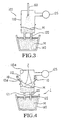
- Japanese Patent Application Laid-open No. Hei-4-289113, Hei-4-289114 and Hei-4-308029 disclose other apparatuses. These apparatuses are constituted as follows. That is, as shown in FIG. 3, a height adjustable lance nozzle 160 is installed on the ceiling of the RH vessel 110, for injecting argon gas. During the decarburization of molten steel M for manufacturing ultra low carbon steel, argon gas is injected through the lance nozzle 160 onto the surface of molten steel M. When the carbon content of molten steel reaches 50 ppm, the lance nozzle 160 is dipped into molten steel M within the vessel so as to inject argon gas into molten steel M, thereby manufacturing ultra low carbon steel.
- the lance nozzles 150 and 160 are made of copper.
- argon and oxygen are injected onto the surface of molten steel M, so that the decarburization speed for ultra low carbon steel is promoted, and that the internal temperature of the vessel is prevented from being decreased too low.
- the internal temperature of the vacuum vessel is raised to 800 to 1200°C, with the result that the lance made of copper is liable to be damaged or partially melted. If the cooling water is leaked, cooling water intensely reacts with molten steel of 1600°C, with the possibility that the vacuum vessel may explode.
- Japanese Patent Application Laid-open No. Sho-64-217 discloses another apparatus.
- two straight tubes are installed on the side wall of the RH vessel, and carbon monoxide is injected through the straight tubes (single layer tubes) during refining, while oxygen is injected through a lance which is installed on the ceiling of the RH.
- the combustion of carbon monoxide decreases temperature drop of molten steel during refining.
- Another known apparatus comprises a plurality of single layer straight tubes are installed with different height on the side wall of the RH vessel.
- oxygen is injected onto the surface of molten steel within the RH vessel.
- the oxygen stream Since the nozzle for injecting oxygen is attached to the straight tube, the oxygen stream does not form a jet stream, but forms the oval shape of FIG. 14A. Injected oxygen gas is used to supply oxygen into molten steel.
- European patent application number 0 584 814 discloses an apparatus in which molten steel is efficiently vacuum treated in a vacuum treatment vessel provided with a top blow lamp capable of injecting an oxygen gas and a fuel gas at desired flow rates, respectively, onto molten steel on the top of the vacuum treatment vessel in a freely vertically moveable manner by conducting an appropriate combination of the step of setting the lower end of the top blow lamp to a level of not more than 2mm from the surface of molten steel bath and injecting only an oxygen gas into the molten steel and a step of setting the lower end of the top blow lamp to a level of 1m or more from the surface of molten steel bath and injecting both of oxygen gas and a fuel gas from the top blow lamps onto the molten steel, thereby preventing a decrease in the temperature of molten steel during the vacuum treatment and also preventing the position of the molten steel on the inside wall of the vacuum treatment vessel without using a large scale heater of electrical resistance type.
- the top blow lamp comprises an oxygen injection region comprising a throat part and
- Japanese patent application number JP-A-60184619 discloses a method and apparatus for obtaining low nitrogen steel subjected to denitrification treatment down to a desired low nitrogen level by utilising a vacuum degassing treatment by subjecting the crude high carbon molten steel produced in a steel making furnace to top blowing of gaseous O 2 under the reduced pressure to decarburize said steel and accelerating the denitrification arising in this stage.
- the present inventors carried out researches and studies, and the present inventors came to propose the present invention based on the results of the researches and studies.
- the apparatus for refining molten steel for manufacturing ultra low carbon steel includes: an RH vacuum-degassing device consisting of a vessel, and a snorkel that composed of an up-leg and a down-leg, and the apparatus further includes: a plurality of gas injecting lance nozzles each consisting of an inner tube and an outer tube, and installed above the surface of the molten steel on a side wall of the vacuum vessel of the RH vacuum-degassing device at a height 1.9 to 3.0 times the radius of the vessel so as to inject gas toward molten steel within the vessel; the inner tube including a throat for making a jet stream of super-sonic velocity; and the outer tube injecting cooling gas for cooling the inner tube; further features of the apparatus according to the invention are set out in claim 1.
- the method for refining molten steel for manufacturing ultra low carbon steel by using an RH vacuum-degassing facility including a vessel and snorkel consisting of an up-leg and a down-leg according to the present invention includes the steps of:
- the molten steel refining apparatus includes a plurality of gas spouting lance nozzles 10 which is installed on the side wall of a vessel 110 of the conventional RH vacuum degassing device.
- Each of the lance nozzles 10 consists of an inner tube 12 and an outer tube 14.
- the inner tube 12 injects oxygen or oxygen containing gas in the form of a jet stream, and the outer tube 14 injects cooling gas for cooling the inner tube 12.
- the inner tube 12 of the lance nozzle 10 includes a throat 17 which forms a jet stream of super-sonic velocity during the injection of oxygen or oxygen containing gas.
- a leading end portion 10a of the lance nozzle 10 should be preferably disposed evenly with an inner wall 110a of the vessel 110.
- the lance nozzles 10 which are installed on the side wall of the vacuum vessel should be provided in a number of preferably 2 or 4. The reasons are is as follows. That is, if only one lance nozzle 10 is installed, the size of the lance nozzle 10 should be large so as to sufficiently inject oxygen, and therefore, a difficulty is encountered in carrying out the maintenance. If the lance nozzle 10 is installed in a number of 3, it is difficult to install the nozzles 10 symmetrically on the side wall of the vessel 110. Therefore, the flow of the molten steel may be impeded, and it is difficult to set the fire spot on the surface of the molten steel.
- the lance nozzle 10 is installed in a number of 5 or more, the following difficulties are encountered. That is, the time period of supplying oxygen gas is much shorter than that of carrying out the decarburization.' During the period when the oxygen gas is not injected, inert gas such as argon or nitrogen should be supplied through the outer tube 14, so that the inner tube 12 can be protected from thermal melting loss, and that skull can be prevented from being adhered. Nitrogen can be used when manufacturing ultra low carbon steel with no limitation in the nitrogen content. Thus, in the case where the number of the lance nozzles 10 is 5 or more, the outer tube 14 has to inject cooling gas in an increased amount. Therefore, not only the vacuum level is lowered, but also the maintenance of the lance nozzle 10 becomes difficult. Therefore, the lance nozzles 10 should be preferably installed in a number of 2 or 4.
- the lance nozzles 10 should be preferably installed above the surface of molten steel M at a height 1.9 to 3.0 times of the vessel radius. If the height is less than 1.9 times of the vessel radius, the angle ⁇ 1 between the lance nozzle 10 and the inner wall 110a of the vessel becomes too small in the relative terms. Therefore, during the installation of the lance nozzles 10, it becomes difficult to cut the refractory material around the side wall of the vessel. Further, the oxygen jet stream collides with the refractory material located lower part of the lance nozzle 10, and therefore, the life expectancy of the refractory material is shortened.
- the reaction efficiency of the oxygen jet stream becomes low due to the high level of the lance nozzle 10. Further, depending on the cases, the oxygen jet stream collides with the opposite side wall and results in shortening of the life expectancy of the collided portion.
- the optimum height of the lance nozzle from the top of molten steel should be 1976 mm to 3120 mm.
- the angle ⁇ 1 between the lance nozzle 10 and the side wall of the vessel should be preferably 20 to 35°. If the angle ⁇ 1 is less than 20°, the oxygen jet stream Z collides with the refractory located below the lance nozzle and results in shortening of the refractory life. On the other hand if the angle ⁇ 1 is more than 35°, the oxygen jet stream Z departs from the fire spot of the surface of molten steel and hits the refractory material of the opposite side wall of the vessel. Consequently, the refractory life is greatly shortened, and therefore, the injection of oxygen gas becomes practically impossible in this case.
- a dotted line L1 connecting the two lance nozzles 10 and passing through the center of the vessel should form an angle ⁇ 2 of 60 to 120° relative to a dotted line L2 connecting an up-leg 121 and a down-leg 122 of a snorkel 120.
- the angle ⁇ 2 should be preferably 60 to 120°.
- the lance nozzles 10 In the case where the lance nozzles 10 are installed in a number of 4 as shown in FIG. 6, the lance nozzles 10 have to be disposed as follows. That is, straight lines L3 and L4 which connect the two opposite pairs of the lance nozzles 10 should pass through the center C of the vessel 110, and the two straight lines L3 and L4 should cross with each other with rectangles. Thus in the case where four lance nozzles 10 are installed, it is most effective to make the straight lines L3 and L4 pass through the center of the vacuum vessel, and to make the two straight lines L3 and L4 cross with each other with rectangles.
- each of the oxygen injection lance nozzles 10 consists of an inner tube 12 and an outer tube 14.
- the inner and outer tubes 12 and 14 are coaxially installed around a center line H. It is preferable to provide a gap of 2 to 4 mm between an outer circumference of the inner tube 12 and an inner circumference 14a of the outer tube 14. If the mentioned gap is less than 2 mm, the cross sectional area of the space between the inner and outer tubes 12 and 14 is too small, and therefore, cooling gas cannot be supplied in sufficient amount. Further, in manufacturing the lance nozzle 10, it is difficult to make the inner and outer tubes 12 and 14 coaxially disposed around the center line H, and to make the inner and outer tubes 12 and 14 have the same thickness.
- the mentioned gap is more than 4 mm, the cross sectional area of the mentioned space becomes too large, and therefore, cooling gas injection rate becomes too high, with the result that the vacuum level is lowered. Therefore it is preferable to provide a gap of 2 to 4 mm.
- the inner and outer tubes 12 and 14 should be preferably made of stainless steel, refractory, ceramic, or alloy metal which can retain the proper strength at a temperature of 1200°C or over.
- the thickness of the inner and outer tubes 12 and 14 should be preferably 3-6 mm, and the reason is as follows. That is, if the thickness is less than 3 mm, the tube cannot withstand against the pressure of the oxygen gas or the argon gas. If the thickness is more than 6 mm, there is the disadvantage that the cost of the lance nozzle 10 is increased.
- the inner circumferential surface of the inner tube 12 of the lance nozzle 10 is narrowed coming toward a throat 17, and a cylindrical portion 17a is formed at the throat 17. Then it is expanded with a constant angle ⁇ 3, and a maximum inside diameter R2 is formed at the leading end 10a of the lance nozzle 10.
- the cylindrical portion (straight portion) 17a of the throat 17 should preferably have a length of 4 to 6 mm, and the reason is as follows. That is, if the length is less than 4 mm, it cannot withstand against the gas pressure. If the length is more than 6 mm, friction is increased under applied gas pressure, with the result that gas pressure is decreased, thereby causing a disadvantage in injecting gas.
- the angle ⁇ 3 of the leading end portion should be preferably 3 to 10°, and the reason is as follows. That is, with an angle of 3°, a super-sonic velocity cannot be obtained. If the angle exceeds 10°, strays from the jet stream occur, and the flow velocity is slowed.
- the ratio of the inside diameter R1 of the throat 17 to the inside diameter R2 of the leading end portion 10a of the nozzle 10 should be preferably 1.1 to 3.0.
- the reason is as follows. That is, if the ratio (R2/R1) is less than 1.1, a super-sonic velocity cannot be obtained. If the ratio exceeds 3.0, supply pressure of oxygen gas has to be very high, and the required level of pressure cannot be industrially obtained.
- Molten steel which has undergone the converter refining process is tapped to the teeming ladle 140, and the ladle 140 is carried to the refining apparatus of the present invention.
- a circulating gas is supplied into an up-leg 121 by means of a circulation gas supplying device 130, while the teeming ladle 140 is raised.
- a vacuum pump 125 is activated to lower the internal pressure of the vessel 110, so that molten steel M of the teeming ladle 140 would ascend through an up-leg 121 into the vessel 110.
- the rising height of the molten steel within the vessel 110 becomes different depending on pressure difference between external air and interior of vessel 110. For example, if internal pressure of the vessel is 150 mbar, the rising height of the molten steel becomes 200 mm.
- oxygen gas or oxygen containing gas is injected through the inner tube 12 of the lance nozzle 10 of the refining apparatus 1 toward the surface of molten steel, in such manner that a jet stream should be formed.
- cooling gas is injected through the outer tube 14 to cool the inner tube 12.
- the gas injection through the inner tube 12 is carried out for at least 3 minutes from the start of injection or for maximum up to the end of decarburization. Gas injection through the outer tube 14 is carried out until the refining is completed.
- oxygen gas is injected with a super-sonic velocity before the vacuum level of the vacuum vessel 110 attains to 150 mbar, then large cavity D is formed on the surface of molten steel M as shown in the FIG. 15. Therefore, it is apprehended that demage may occur on the bottom part of refractory material in the vessel. Therefore it is preferable that the injection of oxygen gas or oxygen containing gas should start after 150 mbar is reached.
- Oxygen containing gas which is injected through the inner tube 12 of the lance nozzle 10 should be preferably mixture of oxygen and carbon monoxide.
- the proportion of carbon monoxide within gas mixture should be preferably not to exceed 30%. If it exceeds 30%, the decarburization reaction of Equation 2 (to be mentioned later) is impeded, and the reaction of Equation 3 cannot be realized. Further, amount of carbon monoxide is sucked into a vacuum pump 125 in increased amount, with the result that the environmental pollution is aggravated, and that the life expectancy of the lance nozzle 10 is shortened.
- cooling gas which is injected through the outer tube 14 of the lance nozzle 10 may consists of argon gas, carbon dioxide, other inert gases, carbon monoxide-containing mixture gas or carbon dioxide containing mixture gas.
- Nitrogen as an inert gas may be used for manufacturing an ultra low carbon steel in which the nitrogen content is not regulated.
- the inner tube 12 is cooled in an easy manner, as well as saving argon, and therefore, the. manufacturing cost for molten steel can be saved.
- oxygen sources such as iron ore or mill scale may be injected at high speed through the inner tube 12 of the lance nozzle 10 together with the carrier gas such as argon or oxygen toward surface of molten steel M.
- the carrier gas such as argon or oxygen toward surface of molten steel M.
- the lance nozzle should be preferably made of ceramic or refractory material, and gas which is injected through the outer tube 14 should preferably consist of carbon monoxide.
- the inner tube 12 is easily worn out by iron ore or mill scale so as to shorten the life of the lance nozzle 10.
- the reason why carbon monoxide is injected through the outer tube 14 is for compensating the temperature based on the reaction of Equation 3.
- Inection pressure of oxygen or oxygen containing gas which is injected through the inner tube 12 of the lance nozzle 10 should be preferably 8.5 to 13.5 Kg/cm 2 .
- injection pressure is less than 8.5 Kg/cm 2
- the inside diameter of the inner tube 12 of the lance nozzle 10 has to be large for ensuring required amount of oxygen.
- the cooling gas such as inert gas should be supplied in increased amount through the outer tube 14 during refining, and therefore, the vacuum level may be aggravated.
- the diameter of the inner tube 12 can be reduced, but the depth of cavity or depressions D which are formed on the surface of molten steel is increased, thereby shortening the life expectancy of the bottom refractory of the vessel 110.
- the injection rate of oxygen or oxygen containing gas should be preferably 20 to 50 Nm 3 /min. If the injection rate is less than 20 Nm 3 /min, the injection time period is increased, and therefore, the refining time is increased.
- the injection rate is more than 50 Nm 3 /min, the injection time period is shortened, but the oxygen reaction efficiency is decreased, because large amount of oxygen is injected within a short period of time. Further, the diameter of the inner tube 12 should be made large, and the cooling gas should be supplied in increased amount through the outer tube 14, with the result that the vacuum level is aggravated.
- the amount of the oxygen gas which is injected onto molten steel M is adjusted in accordance with the carbon content of the molten steel in the following manner. That is, for each 0.01 weight % of carbon within the molten steel, the oxygen gas should be injected preferably in amount of 0.9 to 1.2 Nm 3 per ton of molten steel (Nm 3 /T-S).
- oxygen is less than 0.9 Nm 3 /T-S, then decarburization reaction and the post combustion reaction become low in relative terms. If it exceeds 1.2 Nm 3 /T-S, the decarburization reaction and the post combustion reaction can be obtained as much as required, but the oxygen concentration within molten steel becomes excessively high. Therefore, deoxidizing agent has to be used too much, and the product quality is deteriorated.
- Cooling gas which is injected through the outer tube 14 should have pressure of 3.0 to 5.0 Kg/cm 2 preferably, while its injection rate should be preferably 3.0 to 5.0 Nm 3 /min.
- pressure is less than 3.0 Kg/cm 2 , the diameter of the outer tube 14 has to be increased for injection gas as much as the required amount, and therefore, the manufacturing cost of the. lance nozzle is increased. If pressure is more than 5.0 Kg/cm 2 , the diameter of the outer tube is decreased, and therefore, it is economically advantageous. However, gas which has been injected from the outer tube 14 collides with the oxygen jet Z of the inner tube 12 immediately after departure from the outer tube, and therefore, the oxygen reaction efficiency is decreased.
- gas of the outer tube 14 has an injection rate of less than 3.0 Nm 3 /min, required cooling efficiency cannot be obtained. Therefore, the temperature of the inner tube 12 rises, and therefore, a melting loss occurs in the inner tube 12, thereby shortening the life expectancy of the inner tube 12.
- the injection rate is more than 5.0 Nm 3 /min, gas supply is increased, and therefore, the vacuum level may be aggravated. Therefore, it is preferable to limit the injection rate to 3.0 to 5.0 Nm 3 /min.
- the gas which is injected through the outer tube 14 performs the role of preventing the inner tube 12 from being melted by a radiation heat, and therefore, the gas should have a temperature of preferably 30°C or below. At the temperature above this level, required cooling capability cannot be obtained.
- the lance nozzles may be provided in the number of four.
- oxygen gas or oxygen containing gas is injected at a rate of 5-10 Nm 3 /min through the inner tubes of the lance nozzles 10 which are installed at the left and right sides of the immersion tube 120 (FIG. 6).
- oxygen gas or oxygen containing gas is injected at a rate of 20-50 Nm 3 /min.
- concentration of carbon monoxide within the exhaust gas of the refining apparatus is controlled to preferably 1% or less.
- the lance nozzles may be provided in a number of two.
- oxygen gas or oxygen containing gas is injected at a rate of 5-10 Nm 3 /min through the inner tubes of the lance nozzles 10, while the outer tube 14 is made to inject cooling gas at a rate of 3-5 Nm 3 /min.
- the inner tubes are made to inject oxygen gas in an increased rate of 20-50 Nm 3 /min, while maintaining the injection of cooling gas by the outer tube at a rate of 3-5 Nm 3 /min.
- cooling gas is injected through the inner tube until the completion of the refining, so that skull can be prevented from being adhered.
- the oxygen gas which is injected by the inner tube 12 toward the surface of molten steel forms a jet stream Z as shown in FIG. 9.
- decarburization reaction as shown in Equation 2 below.
- the oxygen gas which forms a jet stream Z as shown in FIG. 15 strongly pushes molten steel, so as to form cavity D. Consequently, the surface area in which the decarburization reaction occurs is increased, and the reaction of Equation 2 occurs on the surface. Therefore, the carbon component within molten steel can be easily decreased, and the decarburization time period can be effectively shortened.
- oxygen gas is that spouted through the lance nozzle 10 of the refining apparatus.
- the [C] is the carbon which is dissolved within molten steel.
- lance nozzles 10 were installed in an RH vacuum degassing apparatus having a capacity of 250 tons.
- the height of lance nozzles 10 was 2800 mm above the surface of molten steel M, i.e., 2.7 times of inside vessel diameter (1040 mm).
- the angle between the lance nozzle 10 and the side wall of the vessel was 20 degrees, and all of the four lance nozzles 10 had the same angle.
- the lance nozzle 10 was made of stainless steel, while the inside diameter R1 of the throat 17 and the exit diameter R2 of the leading end portion 10a were 9.9 mm and 12.4 mm respectively.
- the angle ⁇ 3 of the divergent section was 6 degrees, the gap between the inner tube 12 and the outer tube 14 was 3 mm, and the length of the cylindrical portion 17a of the throat 17 was 4 mm.
- the carbon content within molten steel M was 450 ppm, and the target carbon content of the extra low carbon steel was 50 ppm.
- the inner tubes 12 of the nozzles 10 were made to inject oxygen gas with pressure of 9.5 Kg/cm 2 and at an injection rate of 30 Nm 3 /min.
- the outer tubes 14 were made to inject argon with pressure of 4.0 Kg/cm 2 and at an injection rate of 4 Nm 3 /min.
- oxygen gas was injected in an amount of 0.60 Nm 3 per ton of the molten steel for 6 minutes starting from a vacuum level of 150 mbar. Under this condition, the total decarburization time period was limited to 16 minutes, and after the decarburization of 16 minutes, deoxidation was carried out for 1 minute.
- Equation 4 rate constant of decarburization Kc were calculated based on Equation 4 below. These constants together with that of a comparative example are illustrated in FIG. 10.
- C(17) and C(0) represent the carbon contents at 17 minute and 0 minute respectively.
- T(17) and T(0) represent the temperatures of the molten steel at 17 minute and 0 minute after the start of the decarburization respectively.
- the refining according to the present invention showed that the rate constant of decarburization Kc reached 0.14 to 0.17.
- the average value was 0.16, and this was significantly higher than that of the comparative example in which Kc was 0.10 to 0.13, and the average was 0.12.
- the present invention showed that the carbon content was 16 to 25 ppm, the average being 20 ppm, while the comparative example showed that it was 35 to 45 ppm, the average being 42 ppm. Therefore it was apparent that the carbon content was significantly lower in the present invention compared with the comparative example.
- the temperature drop rate ⁇ was -0.8 to -1.2, the average value being -1.0. Meanwhile in the comparative example, the temperature drop rate was -1.3 to -1.8, the average being -1.5. This witnesses that a large amount of heat was generated based on Equation 3.
- the refining process according to the present invention and the comparative example were carried out 30 times respectively, and the degree of the adherence of skull was observed by the human eyes. The result showed that the degree of the adherence with the present invention was much lower than that of the comparative example. Further, when the experiment was carried out. by over 100 times, a symptom of the explosion due to the leakage of lance cooling fluid could not be found at all during the injection of oxygen through the water cooled lances 150 and 160.
- oxygen gas was injected at a rate of 5 Nm 3 /min through the inner tubes 12 of the lance nozzles 10 which were installed at the left and right sides of the immersion tubes 120 (FIG. 6) and on the wall of the vessel. After elapsing of 3 minutes, the injection was increased to 10 Nm 3 /min, and after elapsing of 10 minutes, the injection was decreased to 5 Nm 3 /min. Then upon completion of the decarburization, the injection was terminated.
- oxygen gas was injected at a rate of 20 Nm 3 /min from 3 minute to 9 minute after the start of the decarburization, and this was equivalent to 0.6 Nm 3 of oxygen per ton of molten steel. This was for promoting the decarburization reaction of Equation 2.
- the method of the present invention showed a higher rate constant of decarburization Kc compared with that of the comparative example as shown in FIG 10.
- the decarburization capability for the ultra low carbon steel was promoted, and at the same time, the post combustion reaction was maximized, so that carbon monoxide can be prevented from being discharged into the atmospheric air.
- the rate constant of decarburization Kc reached 0.16 to 0.17, but the carbon monoxide content within the exhaust gas of the refining apparatus was maintained at only 1.0 volume % or less.
- This example was executed at conditions same as those of Example 1, except the conditions of injection oxygen gas and cooling gas.
- oxygen gas was injected at a rate of 30 Nm 3 /min with pressure of 9.5 Kg/cm 2 .
- mixture consisting of argon and carbon monoxide at a ratio of 8:2 was injected at a rate of 4 Nm 3 /min with pressure of 4.0 Kg/cm 2 .
- oxygen gas was injected in an amount of 0.60 Nm 3 per ton of molten steel through the inner tubes 12, while mixture gas consisting of argon and carbon monoxide was injected in an amount of 0.25 Nm 3 per ton of molten steel. The injection was carried out from the start of the decarburization to the completion of the decarburization.
- Example 1 the rate constant of decarburization Kc, the carbon content within molten steel at 17 minute after the start of the decarburization, the temperature drop rate ⁇ , and the post combustion rate were checked. The results are shown in FIGs. 10, 11, 12 and 13 respectively.
- the method of the present invention showed a larger rate constant of decarburization Kc compared with that of the comparative example. Further, compared with the comparative example, the carbon content within molten steel was low, molten steel temperature drop rate ⁇ was small, and the post combustion rate was high.
- Oxygen gas was injected through the inner tubes 12, and industrial carbon monoxide was injected through the outer tubes 14 at a rate of 4 Nm 3 /min with a pressure of 4.0 Kg/cm 2 .
- the inner and outer tubes were made of ceramic material.
- Example 1 the rate constant of decarburization Kc, the carbon content within molten steel at 17 minute after the start of the decarburization, the temperature drop rate ⁇ , and the post combustion rate were checked. The results are shown in FIGs. 10, 11, 12 and 13 respectively.
- the method of the present invention showed a larger rate constant of decarburization Kc compared with the comparative example. Further, compared with the comparative example, the carbon content within molten steel was low, the molten steel temperature drop rate ⁇ was small, and the post combustion rate was high.
- the reason why the molten steel temperature drop rate was further decreased was that carbon monoxide (which was) injected through the outer tubes participated in the post combustion reaction of Equation 3, thereby generating large amount of heat.
- the reason why the secondary combustion rate was decreased in the relative terms was that a part of carbon monoxide of the outer tube could not effect the secondary combustion reaction, but was discharged in exhaust gas. This is the judgment of the present inventors.
- This example was executed at conditions same as those of Example 3, except that the inner tubes 12 were made to inject oxygen, and the outer tubes 14 were made to inject an industrial carbon dioxide gas at a rate of 45 Nm 3 /min with a pressure of 4.0 Kg/cm 2 .
- Example 1 the rate constant of decarburization Kc, the carbon content within the molten steel at 17 minute after the start of the decarburization, the temperature drop rate ⁇ , and the post combustion rate were checked. The results are shown in FIGs. 10, 11, 12 and 13 respectively.
- the method of the present invention showed a larger rate constant of decarburization Kc compared with that of the comparative example. Further, compared with the comparative example, the carbon content within molten steel was low, molten steel temperature drop rate ⁇ was small, and the post combustion rate was high.
- the post combustion rate was greatly increased, while molten steel temperature drop rate was increased in the relative terms.
- the reason is judged to be that the post combustion rate was calculated based on Equation 6, and carbon dioxide from the outer tubes resulted in an increase of carbon dioxide in the exhaustion gas. It is conjectured that carbon dioxide from the outer tubes actually inhibit the post combustion reaction, in view of the fact that the molten steel temperature drop rate was increased compared with Example 3.
- This example was executed at conditions same as those of Example 1, except that the inner tubes were made to inject mixture gas consisting of oxygen and carbon monoxide at a ratio of 8:2, and the outer tubes were made to inject argon.
- Example 1 the rate constant of decarburization Kc, the carbon content within molten steel at 17 minute after the start of the decarburization, the temperature drop rate ⁇ , and the post combustion rate were checked. The results are shown in FIGs. 10, 11, 12 and 13 respectively.
- the method of the present invention showed a larger rate constant of decarburization Kc compared with that of the comparative example. Further, compared with the comparative example, the carbon content within molten steel was low, the molten steel temperature drop rate ⁇ was small, and the post combustion rate was high.
- the inner and outer tubes 12 and 14 of the lance nozzles 10 were made of fine ceramic.
- the inner tubes 12 were made to inject oxygen at a rate of 10 Nm 3 /min, and 40 Kg of mill scale was injected simultaneously.
- the mill scale was a byproduct which was recovered from a continuous casting process and a hot rolling process of a steel mill.
- the steel component of the mill scale was sorted by means of a magnet, and was crushed to a particle size of 0.5 mm or less.
- the outer tubes were made to inject carbon monoxide at a rate of 4 Nm 3 /min with a pressure of 4.0 Kg/cm 2 from the start of the decarburization to its completion.
- the injected amount of oxygen was equivalent to 0.25 Nm 3 per tone of molten steel.
- Example 1 the rate constant of decarburization Kc, the carbon content within molten steel at 17 minute after the start of the decarburization, the temperature drop rate ⁇ , and the post combustion rate were checked. The results are shown in FIGs. 10, 11, 12 and 13 respectively.
- the method of the present invention showed a larger rate constant of decarburization Kc compared with that of the comparative example. Further, compared with the comparative example, the carbon content within molten steel was low, the molten steel temperature drop rate ⁇ was small, and the post combustion rate was high.
- the carbon content in the finally decarburized molten steel was further decreased.
- the reason is that the injected mill scale deeply intrudes into molten steel so as to be decomposed into steel and soluble oxygen.
- oxygen was supplied to molten steel, and at the same time, the sites for decarburization were furnished.
- ultra low carbon steel with a carbon content of 20 ppm or less can be manufactured in a stable manner.
- the decarburization time period for manufacturing ultra low carbon steel can be significantly reduced, the molten steel temperature drop rate can be effectively reduced during the decarburization, and the skull on the inner wall of the vessel can be decreased. Further, when the oxygen gas is spouted through water cooled lance nozzles, the danger of lance cooling water leakage can be excluded.
Landscapes
- Chemical & Material Sciences (AREA)
- Engineering & Computer Science (AREA)
- Materials Engineering (AREA)
- Metallurgy (AREA)
- Organic Chemistry (AREA)
- Treatment Of Steel In Its Molten State (AREA)
Abstract
Description
- The present invention relates to an apparatus for refining molten steel in a secondary refining process to manufacture ultra low carbon steel and a method for refining molten steel by utilizing the apparatus.
- Generally, when an ultra low carbon steel with a carbon content of 70 ppm or less is manufactured, an RH vacuum degassing apparatus (to be called "RH" below) of FIG. 1 is used. In the method using this apparatus, when molten steel which is tapped from a converter (not shown in the drawings) without killing during tapping arrives at the RH, firstly argon (Ar) gas is injected from a circulation
gas supplying device 130, and at the saine time, asnorkel 120 is dipped into a molten steel M which is contained within aladle 140. Further at the same time, avacuum pump 125 is activated to reduce the internal pressure of avessel 110 to several Torr or several scores of Torr. Under this condition, molten steel M in theladle 140 ascends into the interior of the vacuum vessel owing to the pressure difference between thevessel 110 and atmosphere. At the same time, a decarburizing reaction occurs on the surface of molten steel M as shown inEquation 1 below. As the decarburizing reaction proceeds, the carbon content within molten steel M is decreased, and after elapsing of 15 to 25 minutes, the carbon content within molten steel M reaches 70 to 25 ppm. - That is, in the case where molten steel is refined by using the RH of FIG. 1, a period of 15 minutes or more is required in reducing the carbon content to 70 ppm or less. Further, the temperature of molten steel is lowered by 1.5°C per minute during the decarburization process, this being a problem.
- Meanwhile, Japanese Patent Application Laid-open No. Sho-52-88215 and Sho-52-89513 disclose molten steel refining apparatuses for manufacturing ultra low carbon steel. These apparatuses are constituted as follows. That is, as shown in FIG. 2, a
lance nozzle 150 is installed on the ceiling of theRH vessel 110, for injecting gaseous oxygen so as to shorten the decarburization period when producing ultra low carbon steel. Thus during the decarburization of molten steel, gaseous oxygen is injected through thelance nozzle 150 onto the surface of molten steel within the vessel at a high speed. - Further, Japanese Patent Application Laid-open No. Hei-4-289113, Hei-4-289114 and Hei-4-308029 disclose other apparatuses. These apparatuses are constituted as follows. That is, as shown in FIG. 3, a height
adjustable lance nozzle 160 is installed on the ceiling of theRH vessel 110, for injecting argon gas. During the decarburization of molten steel M for manufacturing ultra low carbon steel, argon gas is injected through thelance nozzle 160 onto the surface of molten steel M. When the carbon content of molten steel reaches 50 ppm, thelance nozzle 160 is dipped into molten steel M within the vessel so as to inject argon gas into molten steel M, thereby manufacturing ultra low carbon steel. - In the apparatuses of FIGs. 2 and 3, the
lance nozzles - However, in the case where the apparatuses of FIGs. 2 and 3 are used for carrying out the decarburization, the internal temperature of the vacuum vessel is raised to 800 to 1200°C, with the result that the lance made of copper is liable to be damaged or partially melted. If the cooling water is leaked, cooling water intensely reacts with molten steel of 1600°C, with the possibility that the vacuum vessel may explode.
- Japanese Patent Application Laid-open No. Sho-64-217 discloses another apparatus. In this apparatus, two straight tubes are installed on the side wall of the RH vessel, and carbon monoxide is injected through the straight tubes (single layer tubes) during refining, while oxygen is injected through a lance which is installed on the ceiling of the RH. Thus, the combustion of carbon monoxide decreases temperature drop of molten steel during refining.
- In the case where carbon monoxide is injected through the straight tubes as in the above method, the combustion of carbon monoxide produces a flame jet, the shape of which is shown in FIG. 14A. In this method, carbon monoxide reacts with oxygen which is injected from the ceiling, and therefore, the temperature of molten steel can be prevented from being excessively dropped. However, the promotion of decarburization reaction is difficult, and the cooling capability of the straight tubes of single layer is deteriorated. Therefore, when the use period is extended, the straight tubes are apt to be melted by radiation heat of molten steel, and the surrounding refractory is melt-damaged.
- Another known apparatus comprises a plurality of single layer straight tubes are installed with different height on the side wall of the RH vessel. Thus, during the decarburization of molten steel, oxygen is injected onto the surface of molten steel within the RH vessel.
- Since the nozzle for injecting oxygen is attached to the straight tube, the oxygen stream does not form a jet stream, but forms the oval shape of FIG. 14A. Injected oxygen gas is used to supply oxygen into molten steel.
- In this method, however, since the injected oxygen gas does not form a jet stream cavity on molten steel surface can not be made. Therefore, the area in which the decarburization occurs cannot be expanded and the problem that the decarburization cannot be promoted occurred.
- Further, in this method, since a plurality of the straight tubes are installed on the side wall of the RH vessel, the evacuating capability for vacuum is greatly deteriorated, and therefore, its practicality is skeptical. Further, as the use period elapses, the single layer straight tubes undergo lowering of the cooling capability, and therefore, melting loss occurs. Further, melting loss occurs in the surrounding refractory materials, and therefore, the life expectancy of the RH vacuum vessel is significantly shortened. Therefore, the apparatus is economically disadvantageous.
- European
patent application number 0 584 814 discloses an apparatus in which molten steel is efficiently vacuum treated in a vacuum treatment vessel provided with a top blow lamp capable of injecting an oxygen gas and a fuel gas at desired flow rates, respectively, onto molten steel on the top of the vacuum treatment vessel in a freely vertically moveable manner by conducting an appropriate combination of the step of setting the lower end of the top blow lamp to a level of not more than 2mm from the surface of molten steel bath and injecting only an oxygen gas into the molten steel and a step of setting the lower end of the top blow lamp to a level of 1m or more from the surface of molten steel bath and injecting both of oxygen gas and a fuel gas from the top blow lamps onto the molten steel, thereby preventing a decrease in the temperature of molten steel during the vacuum treatment and also preventing the position of the molten steel on the inside wall of the vacuum treatment vessel without using a large scale heater of electrical resistance type. The top blow lamp comprises an oxygen injection region comprising a throat part and a tapered region connected to the lower end of the throat part provided along the axial centre line of the lance, and a plurality of fuel gas supply ports provided in the tapered region. - Japanese patent application number JP-A-60184619 discloses a method and apparatus for obtaining low nitrogen steel subjected to denitrification treatment down to a desired low nitrogen level by utilising a vacuum degassing treatment by subjecting the crude high carbon molten steel produced in a steel making furnace to top blowing of gaseous O2 under the reduced pressure to decarburize said steel and accelerating the denitrification arising in this stage.
- In order to solve the problems of the conventional techniques described above, the present inventors carried out researches and studies, and the present inventors came to propose the present invention based on the results of the researches and studies.
- Therefore it is an object of the present invention to provide molten steel refining apparatus and a method therefor, in which the carbon in molten steel can be easily removed, temperature drop of molten steel can be effectively reduced, and a stable operation is realized.
- In achieving the above object, the apparatus for refining molten steel for manufacturing ultra low carbon steel according to the present invention includes: an RH vacuum-degassing device consisting of a vessel, and a snorkel that composed of an up-leg and a down-leg, and
the apparatus further includes: a plurality of gas injecting lance nozzles each consisting of an inner tube and an outer tube, and installed above the surface of the molten steel on a side wall of the vacuum vessel of the RH vacuum-degassing device at a height 1.9 to 3.0 times the radius of the vessel so as to inject gas toward molten steel within the vessel; the inner tube including a throat for making a jet stream of super-sonic velocity; and the outer tube injecting cooling gas for cooling the inner tube; further features of the apparatus according to the invention are set out inclaim 1. - In another aspect of the present invention, the method for refining molten steel for manufacturing ultra low carbon steel by using an RH vacuum-degassing facility including a vessel and snorkel consisting of an up-leg and a down-leg according to the present invention, includes the steps of:
- installing on the side wall of the vessel of the RH vacuum-degassing facility a plurality of gas injecting lance nozzles. each consisting of an inner tube having a straight portion and a throat for forming a jet stream of super-sonic velocity, and an outer tube for injecting cooling gas for cooling the inner tube;
- raising a teeming ladle containing the molten steel, supplying circulating gas into the up-leg, and lowering internal pressure of the vessel so as to make molten steel of the teeming ladle rise through the up-leg into the vessel; and
- injecting oxygen containing gas or oxygen in a form of a jet stream toward molten steel through the inner tube upon recognizing an internal pressure of 150 mbar in the vessel, and injecting cooling gas through the outer tube for cooling the inner tube;
- further features of the method according to the invention are set out in claim 8.
-
- The above object and other advantages of the present invention will become more apparent by describing in detail the preferred embodiment of the present invention with reference to the attached drawings in which:
- FIG. 1 illustrates the constitution of a conventional molten steel refining apparatus for manufacturing ultra low carbon steel;
- FIG. 2 illustrates the constitution of another conventional molten steel refining apparatus for manufacturing ultra low carbon steel;
- FIG. 3 illustrates the constitution of still another conventional molten steel refining apparatus for manufacturing ultra low carbon steel;
- FIG. 4 illustrates the molten steel refining apparatus according to the present invention;
- FIG. 5 illustrates a case of two nozzles provided in the apparatus of the present invention;
- FIG. 6 illustrates a case of four nozzles provided in the apparatus of the present invention;
- FIG. 7 is a sectional view taken in the lengthwise direction of the nozzle provided in the molten steel refining apparatus of the present invention;
- FIG. 8 is a sectional view taken along a line B-B of FIG. 7;
- FIG. 9 illustrates a state in which jet streams are injected from the nozzles of the molten steel refining apparatus according to the present invention;
- FIG. 10 is a graphical illustration showing the decarburization reaction rate for the method of the present invention and a comparative example;
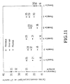
- FIG. 11 is a graphical illustration showing the carbon content within the molten steels for the method of the present invention and a comparative example;
- FIG. 12 is a graphical illustration showing molten steel temperature drop per minute during the decarburization for the present invention and a comparative example;
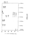
- FIG. 13 is a graphical illustration showing a post combustion rate during the decarburization for the present invention and a comparative example;
- FIG. 14 illustrates the stream shape of the injected gas for different shapes of the lance nozzles; and
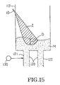
- FIG. 15 illustrates the contour of the surface of molten steel during injection of oxygen in the present invention.
-
- As shown in FIGs. 4 and 7, the molten steel refining apparatus according to the present invention includes a plurality of gas
spouting lance nozzles 10 which is installed on the side wall of avessel 110 of the conventional RH vacuum degassing device. Each of thelance nozzles 10 consists of aninner tube 12 and anouter tube 14. Theinner tube 12 injects oxygen or oxygen containing gas in the form of a jet stream, and theouter tube 14 injects cooling gas for cooling theinner tube 12. - As shown in FIG. 7, the
inner tube 12 of thelance nozzle 10 includes athroat 17 which forms a jet stream of super-sonic velocity during the injection of oxygen or oxygen containing gas. - A
leading end portion 10a of thelance nozzle 10 should be preferably disposed evenly with aninner wall 110a of thevessel 110. - Further, the
lance nozzles 10 which are installed on the side wall of the vacuum vessel should be provided in a number of preferably 2 or 4. The reasons are is as follows. That is, if only onelance nozzle 10 is installed, the size of thelance nozzle 10 should be large so as to sufficiently inject oxygen, and therefore, a difficulty is encountered in carrying out the maintenance. If thelance nozzle 10 is installed in a number of 3, it is difficult to install thenozzles 10 symmetrically on the side wall of thevessel 110. Therefore, the flow of the molten steel may be impeded, and it is difficult to set the fire spot on the surface of the molten steel. - Meanwhile, in the case where the
lance nozzle 10 is installed in a number of 5 or more, the following difficulties are encountered. That is, the time period of supplying oxygen gas is much shorter than that of carrying out the decarburization.' During the period when the oxygen gas is not injected, inert gas such as argon or nitrogen should be supplied through theouter tube 14, so that theinner tube 12 can be protected from thermal melting loss, and that skull can be prevented from being adhered. Nitrogen can be used when manufacturing ultra low carbon steel with no limitation in the nitrogen content. Thus, in the case where the number of thelance nozzles 10 is 5 or more, theouter tube 14 has to inject cooling gas in an increased amount. Therefore, not only the vacuum level is lowered, but also the maintenance of thelance nozzle 10 becomes difficult. Therefore, thelance nozzles 10 should be preferably installed in a number of 2 or 4. - Further, the
lance nozzles 10 should be preferably installed above the surface of molten steel M at a height 1.9 to 3.0 times of the vessel radius. If the height is less than 1.9 times of the vessel radius, the angle 1 between thelance nozzle 10 and theinner wall 110a of the vessel becomes too small in the relative terms. Therefore, during the installation of thelance nozzles 10, it becomes difficult to cut the refractory material around the side wall of the vessel. Further, the oxygen jet stream collides with the refractory material located lower part of thelance nozzle 10, and therefore, the life expectancy of the refractory material is shortened. - If the height of the
lance nozzle 10 exceeds 3.0 times of the vessel radius, the reaction efficiency of the oxygen jet stream becomes low due to the high level of thelance nozzle 10. Further, depending on the cases, the oxygen jet stream collides with the opposite side wall and results in shortening of the life expectancy of the collided portion. - Therefore, if the radius of the vessel is 1040 mm, the optimum height of the lance nozzle from the top of molten steel should be 1976 mm to 3120 mm.
- The angle 1 between the
lance nozzle 10 and the side wall of the vessel should be preferably 20 to 35°. If the angle Θ1 is less than 20°, the oxygen jet stream Z collides with the refractory located below the lance nozzle and results in shortening of the refractory life. On the other hand if the angle 1 is more than 35°, the oxygen jet stream Z departs from the fire spot of the surface of molten steel and hits the refractory material of the opposite side wall of the vessel. Consequently, the refractory life is greatly shortened, and therefore, the injection of oxygen gas becomes practically impossible in this case. - Meanwhile, in the case where two
lance nozzles 10 are provided as shown in FIG. 5, the positions of thelance nozzles 10 on the side wall in a plan view should be as follows. That is, a dotted line L1 connecting the twolance nozzles 10 and passing through the center of the vessel should form an angle 2 of 60 to 120° relative to a dotted line L2 connecting an up-leg 121 and a down-leg 122 of asnorkel 120. - If the angle 2 is less than 60° or more than 120°, the igniting point on the surface of the molten steel is biased to an up-leg or a down-leg. Consequently, the flow of the molten steel M which is introduced from the
ladle 140 into thevessel 110 is impeded, and therefore, the angle 2 should be preferably 60 to 120°. - In the case where the
lance nozzles 10 are installed in a number of 4 as shown in FIG. 6, thelance nozzles 10 have to be disposed as follows. That is, straight lines L3 and L4 which connect the two opposite pairs of thelance nozzles 10 should pass through the center C of thevessel 110, and the two straight lines L3 and L4 should cross with each other with rectangles. Thus in the case where fourlance nozzles 10 are installed, it is most effective to make the straight lines L3 and L4 pass through the center of the vacuum vessel, and to make the two straight lines L3 and L4 cross with each other with rectangles. - As shown in FIGs. 7 and 8, each of the oxygen
injection lance nozzles 10 consists of aninner tube 12 and anouter tube 14. The inner andouter tubes inner tube 12 and aninner circumference 14a of theouter tube 14. If the mentioned gap is less than 2 mm, the cross sectional area of the space between the inner andouter tubes lance nozzle 10, it is difficult to make the inner andouter tubes outer tubes - On the other hand, if the mentioned gap is more than 4 mm, the cross sectional area of the mentioned space becomes too large, and therefore, cooling gas injection rate becomes too high, with the result that the vacuum level is lowered. Therefore it is preferable to provide a gap of 2 to 4 mm.
- Meanwhile, the inner and
outer tubes - Meanwhile, the thickness of the inner and
outer tubes lance nozzle 10 is increased. - As shown in FIG. 7, the inner circumferential surface of the
inner tube 12 of thelance nozzle 10 is narrowed coming toward athroat 17, and acylindrical portion 17a is formed at thethroat 17. Then it is expanded with a constant angle Θ3, and a maximum inside diameter R2 is formed at theleading end 10a of thelance nozzle 10. - Under this condition, the cylindrical portion (straight portion) 17a of the
throat 17 should preferably have a length of 4 to 6 mm, and the reason is as follows. That is, if the length is less than 4 mm, it cannot withstand against the gas pressure. If the length is more than 6 mm, friction is increased under applied gas pressure, with the result that gas pressure is decreased, thereby causing a disadvantage in injecting gas. - Meanwhile, the angle 3 of the leading end portion should be preferably 3 to 10°, and the reason is as follows. That is, with an angle of 3°, a super-sonic velocity cannot be obtained. If the angle exceeds 10°, strays from the jet stream occur, and the flow velocity is slowed.
- Meanwhile, the ratio of the inside diameter R1 of the
throat 17 to the inside diameter R2 of theleading end portion 10a of thenozzle 10 should be preferably 1.1 to 3.0. The reason is as follows. That is, if the ratio (R2/R1) is less than 1.1, a super-sonic velocity cannot be obtained. If the ratio exceeds 3.0, supply pressure of oxygen gas has to be very high, and the required level of pressure cannot be industrially obtained. - If the angle 93 of the leading end is 4°, and the ratio (R2/R1) is 1.7, then oxygen gas velocity reaches to Mach 2.0 (630 m/sec).
- Now the method for refining molten steel by using the refining apparatus of the present invention will be described.
- Molten steel which has undergone the converter refining process is tapped to the teeming
ladle 140, and theladle 140 is carried to the refining apparatus of the present invention. - Then a circulating gas is supplied into an up-
leg 121 by means of a circulationgas supplying device 130, while the teemingladle 140 is raised. At the same time, avacuum pump 125 is activated to lower the internal pressure of thevessel 110, so that molten steel M of the teemingladle 140 would ascend through an up-leg 121 into thevessel 110. - Under this condition, the rising height of the molten steel within the
vessel 110 becomes different depending on pressure difference between external air and interior ofvessel 110. For example, if internal pressure of the vessel is 150 mbar, the rising height of the molten steel becomes 200 mm. - After the initiation of the refining, when the internal pressure of the
vacuum vessel 110reaches 150 mbar, oxygen gas or oxygen containing gas is injected through theinner tube 12 of thelance nozzle 10 of therefining apparatus 1 toward the surface of molten steel, in such manner that a jet stream should be formed. At the same time, cooling gas is injected through theouter tube 14 to cool theinner tube 12. - The gas injection through the
inner tube 12 is carried out for at least 3 minutes from the start of injection or for maximum up to the end of decarburization. Gas injection through theouter tube 14 is carried out until the refining is completed. - If oxygen gas is injected with a super-sonic velocity before the vacuum level of the
vacuum vessel 110 attains to 150 mbar, then large cavity D is formed on the surface of molten steel M as shown in the FIG. 15. Therefore, it is apprehended that demage may occur on the bottom part of refractory material in the vessel. Therefore it is preferable that the injection of oxygen gas or oxygen containing gas should start after 150 mbar is reached. - Oxygen containing gas which is injected through the
inner tube 12 of thelance nozzle 10 should be preferably mixture of oxygen and carbon monoxide. - When refining molten steel, mixture of oxygen and carbon monoxide is injected through the
inner tubes 12 of the plurality of thelance nozzles 10 for at least 3 minutes to at most the completion of the decarburization, with a predetermined flow rate. Thus a reaction as shown inEquation 3 to be mentioned later is induced, so that the temperature drop of the molten steel can be effectively reduced. - Under this condition, if the
lance nozzle 10 is made of stainless steel or heat resistant alloy, the proportion of carbon monoxide within gas mixture should be preferably not to exceed 30%. If it exceeds 30%, the decarburization reaction of Equation 2 (to be mentioned later) is impeded, and the reaction ofEquation 3 cannot be realized. Further, amount of carbon monoxide is sucked into avacuum pump 125 in increased amount, with the result that the environmental pollution is aggravated, and that the life expectancy of thelance nozzle 10 is shortened. - Further, cooling gas which is injected through the
outer tube 14 of thelance nozzle 10 may consists of argon gas, carbon dioxide, other inert gases, carbon monoxide-containing mixture gas or carbon dioxide containing mixture gas. Nitrogen as an inert gas may be used for manufacturing an ultra low carbon steel in which the nitrogen content is not regulated. - In the case where mixture of argon and carbon monoxide is used as the cooling gas of the
outer tube 14, carbon monoxide reacts with the oxygen gas as shown inEquation 3 within the vessel, with the result that large amount of heat is generated compared with the case where only argon is used. Meanwhile, in the case where thelance nozzle 10 is made of stainless steel or heat resistant alloy, the volume proportion of carbon monoxide within mixture gas should preferably not exceed 30%. If it exceeds 30%, the reaction ofEquation 3 cannot be realized. Further, amount of carbon monoxide is sucked into avacuum pump 125 in increased amount, with the result that the environmental pollution is aggravated, and that the life expectancy of thelance nozzle 10 is shortened. - In the case where carbon dioxide is injected through the
outer tube 14, theinner tube 12 is cooled in an easy manner, as well as saving argon, and therefore, the. manufacturing cost for molten steel can be saved. - Meanwhile, in the case where molten steel M is refined for manufacturing ultra low carbon steel, oxygen sources such as iron ore or mill scale may be injected at high speed through the
inner tube 12 of thelance nozzle 10 together with the carrier gas such as argon or oxygen toward surface of molten steel M. In this manner, the decarburization period can be easily shortened, and the carbon component can be easily reduced. - The reason is as follows. That is, iron ore or mill scale which is injected at high speed penetrates into molten steel and decomposes into iron and soluble oxygen, thereby supplying oxygen to molten steel and providing sites for decarburization reactions. Here, the lance nozzle should be preferably made of ceramic or refractory material, and gas which is injected through the
outer tube 14 should preferably consist of carbon monoxide. - In the case where the lance nozzle is made of stainless steel or heat resistant alloy, the
inner tube 12 is easily worn out by iron ore or mill scale so as to shorten the life of thelance nozzle 10. The reason why carbon monoxide is injected through theouter tube 14 is for compensating the temperature based on the reaction ofEquation 3. - Inection pressure of oxygen or oxygen containing gas which is injected through the
inner tube 12 of thelance nozzle 10 should be preferably 8.5 to 13.5 Kg/cm2. - If injection pressure is less than 8.5 Kg/cm2, the inside diameter of the
inner tube 12 of thelance nozzle 10 has to be large for ensuring required amount of oxygen. Further, the cooling gas such as inert gas should be supplied in increased amount through theouter tube 14 during refining, and therefore, the vacuum level may be aggravated. - In the case where the injection pressure is more than 13.5 Kg/cm2, there is an advantage that the diameter of the
inner tube 12 can be reduced, but the depth of cavity or depressions D which are formed on the surface of molten steel is increased, thereby shortening the life expectancy of the bottom refractory of thevessel 110. - The injection rate of oxygen or oxygen containing gas should be preferably 20 to 50 Nm3/min. If the injection rate is less than 20 Nm3/min, the injection time period is increased, and therefore, the refining time is increased.
- On the other hand, if the injection rate is more than 50 Nm3/min, the injection time period is shortened, but the oxygen reaction efficiency is decreased, because large amount of oxygen is injected within a short period of time. Further, the diameter of the
inner tube 12 should be made large, and the cooling gas should be supplied in increased amount through theouter tube 14, with the result that the vacuum level is aggravated. - The amount of the oxygen gas which is injected onto molten steel M is adjusted in accordance with the carbon content of the molten steel in the following manner. That is, for each 0.01 weight % of carbon within the molten steel, the oxygen gas should be injected preferably in amount of 0.9 to 1.2 Nm3 per ton of molten steel (Nm3/T-S).
- If oxygen is less than 0.9 Nm3/T-S, then decarburization reaction and the post combustion reaction become low in relative terms. If it exceeds 1.2 Nm3/T-S, the decarburization reaction and the post combustion reaction can be obtained as much as required, but the oxygen concentration within molten steel becomes excessively high. Therefore, deoxidizing agent has to be used too much, and the product quality is deteriorated.
- Cooling gas which is injected through the
outer tube 14 should have pressure of 3.0 to 5.0 Kg/cm2 preferably, while its injection rate should be preferably 3.0 to 5.0 Nm3/min. - If pressure is less than 3.0 Kg/cm2, the diameter of the
outer tube 14 has to be increased for injection gas as much as the required amount, and therefore, the manufacturing cost of the. lance nozzle is increased. If pressure is more than 5.0 Kg/cm2, the diameter of the outer tube is decreased, and therefore, it is economically advantageous. However, gas which has been injected from theouter tube 14 collides with the oxygen jet Z of theinner tube 12 immediately after departure from the outer tube, and therefore, the oxygen reaction efficiency is decreased. - Meanwhile, if gas of the
outer tube 14 has an injection rate of less than 3.0 Nm3/min, required cooling efficiency cannot be obtained. Therefore, the temperature of theinner tube 12 rises, and therefore, a melting loss occurs in theinner tube 12, thereby shortening the life expectancy of theinner tube 12. On the other hand, if the injection rate is more than 5.0 Nm3/min, gas supply is increased, and therefore, the vacuum level may be aggravated. Therefore, it is preferable to limit the injection rate to 3.0 to 5.0 Nm3/min. - The gas which is injected through the
outer tube 14 performs the role of preventing theinner tube 12 from being melted by a radiation heat, and therefore, the gas should have a temperature of preferably 30°C or below. At the temperature above this level, required cooling capability cannot be obtained. - In the present invention, the lance nozzles may be provided in the number of four. During the decarburization of molten steel, oxygen gas or oxygen containing gas is injected at a rate of 5-10 Nm3/min through the inner tubes of the
lance nozzles 10 which are installed at the left and right sides of the immersion tube 120 (FIG. 6). Through the rest of thelance nozzles 10, oxygen gas or oxygen containing gas is injected at a rate of 20-50 Nm3/min. Thus the concentration of carbon monoxide within the exhaust gas of the refining apparatus is controlled to preferably 1% or less. - Or in the present invention, the lance nozzles may be provided in a number of two. At the start of the decarburization of molten steel, oxygen gas or oxygen containing gas is injected at a rate of 5-10 Nm3/min through the inner tubes of the
lance nozzles 10, while theouter tube 14 is made to inject cooling gas at a rate of 3-5 Nm3/min. Then at an intermediate point during the decarburization, the inner tubes are made to inject oxygen gas in an increased rate of 20-50 Nm3/min, while maintaining the injection of cooling gas by the outer tube at a rate of 3-5 Nm3/min. - Further, in the present invention, after the termination of the oxygen gas injection through the
inner tube 12, cooling gas is injected through the inner tube until the completion of the refining, so that skull can be prevented from being adhered. - If molten steel is refined based on the method of the present invention by using the refining apparatus of the present invention, the following phenomenon occurs. That is, the oxygen gas which is injected by the
inner tube 12 toward the surface of molten steel forms a jet stream Z as shown in FIG. 9. Further, on the surface of molten steel M, there occurs decarburization reaction as shown inEquation 2 below. The oxygen gas which forms a jet stream Z as shown in FIG. 15 strongly pushes molten steel, so as to form cavity D. Consequently, the surface area in which the decarburization reaction occurs is increased, and the reaction ofEquation 2 occurs on the surface. Therefore, the carbon component within molten steel can be easily decreased, and the decarburization time period can be effectively shortened. InEquation 2, oxygen gas is that spouted through thelance nozzle 10 of the refining apparatus. The [C] is the carbon which is dissolved within molten steel. - Meanwhile in a
heat preserving zone 20, a reaction occurs between carbon monoxide and oxygen gas. Carbon monoxide which participates in the reaction ofEquation 3 is produced by the reaction ofEquation 2 so as to ascend toward thevacuum pump 125. Oxygen gas ofEquation 3 is that which has been injected through thelance nozzle 10, and as a result of theEquation 3, large amount of heat is generated. Consequently, the internal temperature of the vessel rises, and therefore, skull adhered on the inner wall of the vessel is decreased, while the temperature drop is decreased during the decarburization of molten steel M. - Now the present invention will be described based on actual examples.
- Four
lance nozzles 10 were installed in an RH vacuum degassing apparatus having a capacity of 250 tons. The height oflance nozzles 10 was 2800 mm above the surface of molten steel M, i.e., 2.7 times of inside vessel diameter (1040 mm). The angle between thelance nozzle 10 and the side wall of the vessel was 20 degrees, and all of the fourlance nozzles 10 had the same angle. Thelance nozzle 10 was made of stainless steel, while the inside diameter R1 of thethroat 17 and the exit diameter R2 of theleading end portion 10a were 9.9 mm and 12.4 mm respectively. The angle 3 of the divergent section was 6 degrees, the gap between theinner tube 12 and theouter tube 14 was 3 mm, and the length of thecylindrical portion 17a of thethroat 17 was 4 mm. - The carbon content within molten steel M was 450 ppm, and the target carbon content of the extra low carbon steel was 50 ppm. During the decarburization of molten steel for this ultra low carbon steel, the
inner tubes 12 of thenozzles 10 were made to inject oxygen gas with pressure of 9.5 Kg/cm2 and at an injection rate of 30 Nm3/min. Theouter tubes 14 were made to inject argon with pressure of 4.0 Kg/cm2 and at an injection rate of 4 Nm3/min. For one charge, oxygen gas was injected in an amount of 0.60 Nm3 per ton of the molten steel for 6 minutes starting from a vacuum level of 150 mbar. Under this condition, the total decarburization time period was limited to 16 minutes, and after the decarburization of 16 minutes, deoxidation was carried out for 1 minute. - Then test samples were taken at the time (0 minute) of starting the decarburization and immediately after the decarburization (17 minutes). These samples were put into a carbon/sulphur analyzer to analyze the carbon contents. By utilizing the analyzed values, rate constant of decarburization Kc were calculated based on
Equation 4 below. These constants together with that of a comparative example are illustrated in FIG. 10. InEquation 4, C(17) and C(0) represent the carbon contents at 17 minute and 0 minute respectively. - Further, when 17 minutes were elapsed from the start of the decarburization, the carbon contents of molten steel were measured, and the results are illustrated in FIG. 11.
- Further, at 0 minute and 17 minute after the start of the decarburization, molten steel temperature were measured. Then the temperature drop rates α were calculated based on
Equation 5 below, and the results are illustrated in FIG. 12. - In
Equation 5, T(17) and T(0) represent the temperatures of the molten steel at 17 minute and 0 minute after the start of the decarburization respectively. - Further, the contents of carbon monoxide and carbon dioxide within the exhaust gas of the refining apparatus were measured by using an exhaust gas analyzing instrument. Then the secondary combustion rates were calculated based on
Equation 6 below, and the results are illustrated in FIG. 13. - As shown in FIG. 10, the refining according to the present invention showed that the rate constant of decarburization Kc reached 0.14 to 0.17. The average value was 0.16, and this was significantly higher than that of the comparative example in which Kc was 0.10 to 0.13, and the average was 0.12. Further as shown in FIG. 11, the present invention showed that the carbon content was 16 to 25 ppm, the average being 20 ppm, while the comparative example showed that it was 35 to 45 ppm, the average being 42 ppm. Therefore it was apparent that the carbon content was significantly lower in the present invention compared with the comparative example.
- As shown in FIG. 12, when the molten steel is refined according to the method of the present invention, the temperature drop rate α was -0.8 to -1.2, the average value being -1.0. Meanwhile in the comparative example, the temperature drop rate was -1.3 to -1.8, the average being -1.5. This witnesses that a large amount of heat was generated based on
Equation 3. - As shown in FIG. 13, in the case molten steel was refined according to the method of the present invention, the post combustion rate was 95-82%, the average being 87%, while in the comparative example, the post combustion rate was 5 to 15%, the average being 13%. Therefore post combusion rate of the present invention is significantly higher than that of the comparative example. This witnesses that the reaction of
Equation 3 was very brisk, and it well corresponds to the graph of FIG. 12. - The refining process according to the present invention and the comparative example were carried out 30 times respectively, and the degree of the adherence of skull was observed by the human eyes. The result showed that the degree of the adherence with the present invention was much lower than that of the comparative example. Further, when the experiment was carried out. by over 100 times, a symptom of the explosion due to the leakage of lance cooling fluid could not be found at all during the injection of oxygen through the water cooled
lances - Experiments were carried out at conditions same as those of Example 1, except that the oxygen injection conditions were different as described below. Then the rate constant of decarburization Kc was checked, and the results are illustrated in FIG. 10.
- In this example, at the start of the refining of molten steel, oxygen gas was injected at a rate of 5 Nm3/min through the
inner tubes 12 of thelance nozzles 10 which were installed at the left and right sides of the immersion tubes 120 (FIG. 6) and on the wall of the vessel. After elapsing of 3 minutes, the injection was increased to 10 Nm3/min, and after elapsing of 10 minutes, the injection was decreased to 5 Nm3/min. Then upon completion of the decarburization, the injection was terminated. - This was for realizing the post combustion reaction of
Equation 3. - Meanwhile, through the
inner tubes 12 of the other twolance nozzles 10, oxygen gas was injected at a rate of 20 Nm3/min from 3 minute to 9 minute after the start of the decarburization, and this was equivalent to 0.6 Nm3 of oxygen per ton of molten steel. This was for promoting the decarburization reaction ofEquation 2. - In this example, the method of the present invention showed a higher rate constant of decarburization Kc compared with that of the comparative example as shown in FIG 10.
- In the method of this example, the decarburization capability for the ultra low carbon steel was promoted, and at the same time, the post combustion reaction was maximized, so that carbon monoxide can be prevented from being discharged into the atmospheric air.
- In this example, the rate constant of decarburization Kc reached 0.16 to 0.17, but the carbon monoxide content within the exhaust gas of the refining apparatus was maintained at only 1.0 volume % or less.
- This example was executed at conditions same as those of Example 1, except the conditions of injection oxygen gas and cooling gas.
- That is, through the
inner tubes 12 of thelance nozzles 10, oxygen gas was injected at a rate of 30 Nm3/min with pressure of 9.5 Kg/cm2. Through theouter tubes 14, mixture consisting of argon and carbon monoxide at a ratio of 8:2 was injected at a rate of 4 Nm3/min with pressure of 4.0 Kg/cm2. At each charge of molten steel, oxygen gas was injected in an amount of 0.60 Nm3 per ton of molten steel through theinner tubes 12, while mixture gas consisting of argon and carbon monoxide was injected in an amount of 0.25 Nm3 per ton of molten steel. The injection was carried out from the start of the decarburization to the completion of the decarburization. - The above described experiments were carried out 50 times. Then as in Example 1, the rate constant of decarburization Kc, the carbon content within molten steel at 17 minute after the start of the decarburization, the temperature drop rate α, and the post combustion rate were checked. The results are shown in FIGs. 10, 11, 12 and 13 respectively.
- As illustrated in FIGs. 10 - 13, the method of the present invention showed a larger rate constant of decarburization Kc compared with that of the comparative example. Further, compared with the comparative example, the carbon content within molten steel was low, molten steel temperature drop rate α was small, and the post combustion rate was high.
- This example was executed at conditions same as those of Example 3, except the matters described below.
- Oxygen gas was injected through the
inner tubes 12, and industrial carbon monoxide was injected through theouter tubes 14 at a rate of 4 Nm3/min with a pressure of 4.0 Kg/cm2. In order to prevent corrosion of thelance nozzles 10 by carbon monoxide, the inner and outer tubes were made of ceramic material. - The above described experiments were carried out 10 times. Then as in Example 1, the rate constant of decarburization Kc, the carbon content within molten steel at 17 minute after the start of the decarburization, the temperature drop rate α, and the post combustion rate were checked. The results are shown in FIGs. 10, 11, 12 and 13 respectively.
- As illustrated in FIGs. 10 - 13, the method of the present invention showed a larger rate constant of decarburization Kc compared with the comparative example. Further, compared with the comparative example, the carbon content within molten steel was low, the molten steel temperature drop rate α was small, and the post combustion rate was high.
- In this example, the reason why the molten steel temperature drop rate was further decreased was that carbon monoxide (which was) injected through the outer tubes participated in the post combustion reaction of
Equation 3, thereby generating large amount of heat. On the other hand, the reason why the secondary combustion rate was decreased in the relative terms was that a part of carbon monoxide of the outer tube could not effect the secondary combustion reaction, but was discharged in exhaust gas. This is the judgment of the present inventors. - This example was executed at conditions same as those of Example 3, except that the
inner tubes 12 were made to inject oxygen, and theouter tubes 14 were made to inject an industrial carbon dioxide gas at a rate of 45 Nm3/min with a pressure of 4.0 Kg/cm2. - Since the price of argon is relatively high, the outer tubes were made to inject carbon dioxide instead of argon so as to save the steel manufacturing cost.
- The above described experiments were carried out 10 times. Then as in Example 1, the rate constant of decarburization Kc, the carbon content within the molten steel at 17 minute after the start of the decarburization, the temperature drop rate α, and the post combustion rate were checked. The results are shown in FIGs. 10, 11, 12 and 13 respectively.
- As illustrated in FIGs. 10 - 13, the method of the present invention showed a larger rate constant of decarburization Kc compared with that of the comparative example. Further, compared with the comparative example, the carbon content within molten steel was low, molten steel temperature drop rate α was small, and the post combustion rate was high.
- In this example, the post combustion rate was greatly increased, while molten steel temperature drop rate was increased in the relative terms. The reason is judged to be that the post combustion rate was calculated based on
Equation 6, and carbon dioxide from the outer tubes resulted in an increase of carbon dioxide in the exhaustion gas. It is conjectured that carbon dioxide from the outer tubes actually inhibit the post combustion reaction, in view of the fact that the molten steel temperature drop rate was increased compared with Example 3. - This example was executed at conditions same as those of Example 1, except that the inner tubes were made to inject mixture gas consisting of oxygen and carbon monoxide at a ratio of 8:2, and the outer tubes were made to inject argon.
- The above described experiments were carried out 35 times. Then as in Example 1, the rate constant of decarburization Kc, the carbon content within molten steel at 17 minute after the start of the decarburization, the temperature drop rate α, and the post combustion rate were checked. The results are shown in FIGs. 10, 11, 12 and 13 respectively.
- As illustrated in FIGs. 10 - 13, the method of the present invention showed a larger rate constant of decarburization Kc compared with that of the comparative example. Further, compared with the comparative example, the carbon content within molten steel was low, the molten steel temperature drop rate α was small, and the post combustion rate was high.
- This example was executed at conditions same as those of Example 1, except the matters to be described below.
- In this example, the inner and
outer tubes lance nozzles 10 were made of fine ceramic. During the decarburization, theinner tubes 12 were made to inject oxygen at a rate of 10 Nm3/min, and 40 Kg of mill scale was injected simultaneously. The mill scale was a byproduct which was recovered from a continuous casting process and a hot rolling process of a steel mill. The steel component of the mill scale was sorted by means of a magnet, and was crushed to a particle size of 0.5 mm or less. - The outer tubes were made to inject carbon monoxide at a rate of 4 Nm3/min with a pressure of 4.0 Kg/cm2 from the start of the decarburization to its completion. The injected amount of oxygen was equivalent to 0.25 Nm3 per tone of molten steel.
- The above described experiments were carried out 10 times. Then as in Example 1, the rate constant of decarburization Kc, the carbon content within molten steel at 17 minute after the start of the decarburization, the temperature drop rate α, and the post combustion rate were checked. The results are shown in FIGs. 10, 11, 12 and 13 respectively.
- As illustrated in FIGs. 10 - 13, the method of the present invention showed a larger rate constant of decarburization Kc compared with that of the comparative example. Further, compared with the comparative example, the carbon content within molten steel was low, the molten steel temperature drop rate α was small, and the post combustion rate was high.
- In this example, the carbon content in the finally decarburized molten steel was further decreased. The reason is that the injected mill scale deeply intrudes into molten steel so as to be decomposed into steel and soluble oxygen. Thus oxygen was supplied to molten steel, and at the same time, the sites for decarburization were furnished.
- As seen in the above described examples, if molten steel is refined according to the present invention, ultra low carbon steel with a carbon content of 20 ppm or less can be manufactured in a stable manner.
- According to the present invention as described above, the decarburization time period for manufacturing ultra low carbon steel can be significantly reduced, the molten steel temperature drop rate can be effectively reduced during the decarburization, and the skull on the inner wall of the vessel can be decreased. Further, when the oxygen gas is spouted through water cooled lance nozzles, the danger of lance cooling water leakage can be excluded.
Claims (24)
- An apparatus for refining molten steel for manufacturing ultra low carbon steel comprising:wherein each of said lance nozzles 10 has a leading end portion 10a, and each of said lance nozzles is installed such that said leading end portion 10a is disposed evenly with an inner wall 110a of said vessel 110, said throat 17 has a straight cylindrical portion 17a, and the inner circumferential surface of said inner tube 12 is expanded with constant angle (3) of 3 to 10° towards said leading end portion 10a from said neck throat 17, and on the angle (1) between said gas injection lance nozzle 10 and said side wall of the vessel is in the range of 20 to 35°.an RH vacuum-degassing device consisting of a vessel 110, and a snorkel 120 composed of an up-leg 121 and a down-leg 122, andthe apparatus further comprising:a plurality of gas injection lance nozzles 10 each consisting of an inner tube 12 and an outer tube 14, and installed above the surface of the molten steel on a side wall of said vessel of said RH vacuum-degassing device at a height 1.9 to 3.0 times the radius of said vessel so as to inject gas toward the molten steel within said vacuum vessel;said inner tube 12 including a throat 17 for forming a jet stream of a super-sonic velocity and said outer tube 14 injecting cooling gas for cooling said inner tube 12,
- The apparatus as claimed in Claim 1, wherein two or four lance nozzles 10 are provided.
- The apparatus as claimed in Claim 1, wherein two lance nozzles 10 are provided; and a line L1 connecting said two lance nozzles 10 and passing through a centre of said vessel forms an angle 2 of 60 to 120° relative to a line L2 connecting an up-leg 121 and a down-leg 122 of the said snorkel 120.
- The apparatus as claimed in claim 1, wherein four lance nozzles 10 are provided; and straight lines L3 and L4 which connect two opposite pairs of said lance nozzles 10 pass through a centre C of said vessel 110, and said two straight lines L3 and L4 cross with each other at right angles.
- The apparatus as claimed in Claim 1, wherein a gap of 2 to 4 mm is formed between an outer circumference 12a of said inner tube 12 and an inner circumference 14a of said outer tube 14.
- The apparatus as claimed in Claim 1, wherein said straight cylindrical portion 17a has a length of 4 to 6 mm.
- The apparatus as claimed in Claim 1, wherein an inside diameter R1 of said throat 17 and inside diameter R2 of said leading end portion 10a have a size ratio of 1.1 to 3.0.
- A method for refining molten steel for manufacturing ultra low carbon steel by using an RH vacuum-degassing device including a vacuum vessel 110 and a snorkel 120 consisting of an up-leg 121 and down-leg 122, comprising the steps of:preparing a plurality of gas injection lance nozzles 10 each consisting of an inner tube 12 having a straight portion and a throat for forming a jet stream of supersonic velocity, and an outer tube 14 for injecting cooling gas for cooling said inner tube 12, wherein each of said lance nozzles 10 has a leading end portion 10a disposed evenly with an inner wall 110a of said vessel 110 and an inner circumferential surface of said inner tube is expended with a constant angle (3) of 3 to 10° toward said leading end portion 10a from said neck portion 17, installing said gas injection lance nozzle 10 above the surface of a molten steel on a side wall of said vacuum vessel of said vacuum degassing device at a height 1.9 to 3.0 times the radius of said vacuum vessel at an angle (1) of 20 to 35° so that the lance nozzles would inject the gas toward the molten steel;raising a teeming ladle 140 containing molten steel, supplying circulating gas into said up-leg 121, and lowering internal pressure of said vessel so as to make molten steel of said teeming ladle 140 rise through said up-leg 121 into said vessel 110; andinjecting oxygen containing gas or oxygen in a form of a jet stream toward molten steel through said inner tube 12 upon recognising an internal pressure of 150 mbar in said vessel 110, and injecting cooling gas through said outer tube 14 for cooling said inner tube 12, gas injection through said inner tube being terminated during a period up to 3 minutes after the start of injecting and decarburization completion, and the gas injection through said outer tube 14 being terminated upon completion of the refining.
- The method as claimed in Claim 8, wherein two or four lance nozzles 10 are provided.
- The method as claimed in Claim 8, wherein two lance nozzles 10 are provided; and a line L1 connecting said two lance nozzles 10 and passing through a centre of said vessel forms an angle 2 of 60 to 120° relative to a line L2 connecting said up-leg 121 and said down-leg 122 of the snorkel 120.
- The method as claimed in Claim 8, wherein four lance nozzles 10 are provided; and straight lines L3 and L4 which connect two opposite pairs of said lance nozzles 10 pass through a centre of C of said vessel 110, and said two straight lines L3 and L4 cross with each other at right angles.
- The method as claimed in Claim 8, wherein a gap of 2 to 4 mm is formed between an outer circumference 12a of said inner tube 12 and an inner circumference 14a of said outer tube 14.
- The method as claimed in Claim 8, wherein said throat 17 has a straight cylindrical portion 17a having a length of 4 to 6 mm.
- The method as claimed in Claim 10, wherein an inside diameter R1 of said throat 17 and an inside diameter R2 of said leading end portion 10a have a size ratio of 1.1 to 3.0.
- The method as claimed in any one of Claims 8 to 14, wherein the oxygen containing gas is a mixture of oxygen and carbon monoxide.
- The method as claimed in Claim 15, wherein carbon monoxide is mixed in a proportion of 30 volume % or less.
- The method as claimed in any one of Claims 8 to 14 wherein said inner tube injects a mixture of oxygen and mill scale.
- The method as claimed in any one of Claims 8 to 17, wherein the cooling gas is one selected from a group consisting of an inert gas, carbon dioxide, mixture of inert gas and carbon monoxide, and mixture of inert gas and carbon dioxide.
- The method as claimed in Claim 18, wherein carbon monoxide is mixed with inert gas in a proportion of 30 volume % or less.
- The method as claimed in any one of Claims 8 to 19, wherein oxygen gas or oxygen containing gas is injected through said inner tubes at a rate of 20-50Nm3/min with a pressure of 8.5-13.5 kg/cm2; and cooling gas is injected through said outer tube at a rate of 3-5 Nm3/min with a pressure of 3.0-5.0 kg/cm2.
- The method as claimed in any one of Claims 8 to 14 wherein four lance nozzles are provided; oxygen gas or oxygen containing gas is injected at a rate of 5-10 Nm3/min through said inner tubes of said lance nozzles 10 installed at left and right sides of said snorkel 120 and on the inner wall of said vessel; and oxygen gas or oxygen containing gas is injected through the remaining two inner tubes at a rate of 20-50 Nm3/min, whereby a concentration of carbon monoxide within exhaust gas of said refining apparatus becomes 1% or less.
- The method as claimed in any one of Claims 8 to 14, wherein two lance nozzles are provided; said inner tubes of said lance nozzles 10 are made to inject oxygen gas or oxygen containing gas at a rate of 5-10 Nm3/min; said outer tubes are made to inject cooling gas at a rate of 3-5 Nm3/min; and then said inner tubes are made to inject oxygen gas or oxygen containing gas at an increased rate of 20-50 Nm3/min, while maintaining the spouting of the cooling gas at a rate of 3-5 Nm3/min.
- The method as claimed in any one of Claims 8 to 14, wherein upon completion of injecting oxygen gas or oxygen containing gas through said inner tubes, said inner tubes are made to inject a cooling gas until completion of the refining.
- The method as claimed in Claim 20, wherein upon completion of injection oxygen gas or oxygen containing gas through said inner tubes, said inner tubes are made to inject cooling gas until completion of the refining.
Applications Claiming Priority (3)
| Application Number | Priority Date | Filing Date | Title |
|---|---|---|---|
| KR1019960044524A KR100270113B1 (en) | 1996-10-08 | 1996-10-08 | Ultra-low carbon steels for molten steel production |
| KR9644524 | 1996-10-08 | ||
| PCT/KR1996/000264 WO1998015664A1 (en) | 1996-10-08 | 1996-12-30 | Molten steel smelting apparatus for producing ultra-low carbon steel and a smelting method using this apparatus |
Publications (3)
| Publication Number | Publication Date |
|---|---|
| EP0879896A1 EP0879896A1 (en) | 1998-11-25 |
| EP0879896A4 EP0879896A4 (en) | 1999-12-15 |
| EP0879896B1 true EP0879896B1 (en) | 2002-03-13 |
Family
ID=19476597
Family Applications (1)
| Application Number | Title | Priority Date | Filing Date |
|---|---|---|---|
| EP96944131A Expired - Lifetime EP0879896B1 (en) | 1996-10-08 | 1996-12-30 | Apparatus and process for refining molten steel in the production of ultra-low carbon steel |
Country Status (11)
| Country | Link |
|---|---|
| US (1) | US6156263A (en) |
| EP (1) | EP0879896B1 (en) |
| KR (1) | KR100270113B1 (en) |
| CN (1) | CN1068060C (en) |
| AT (1) | ATE214434T1 (en) |
| BR (1) | BR9611914A (en) |
| DE (1) | DE69619866T2 (en) |
| ID (1) | ID18476A (en) |
| MY (1) | MY123125A (en) |
| RU (1) | RU2150516C1 (en) |
| WO (1) | WO1998015664A1 (en) |
Families Citing this family (14)
| Publication number | Priority date | Publication date | Assignee | Title |
|---|---|---|---|---|
| KR100398380B1 (en) * | 1998-11-02 | 2003-12-18 | 주식회사 포스코 | Molten steel refining method for manufacturing ultra low carbon steel |
| IT1302798B1 (en) | 1998-11-10 | 2000-09-29 | Danieli & C Ohg Sp | INTEGRATED DEVICE FOR THE INJECTION OF OXYGEN AND GASTECNOLOGICS AND FOR THE INSUFFLATION OF SOLID MATERIAL IN |
| RU2215047C2 (en) * | 2001-12-25 | 2003-10-27 | Открытое акционерное общество "Новолипецкий металлургический комбинат" | Device for circulating degassing of steel |
| EP1476584A1 (en) * | 2002-02-22 | 2004-11-17 | Vai Fuchs GmbH | Method for deep decarburisation of steel melts |
| RU2212454C1 (en) * | 2002-09-25 | 2003-09-20 | Шатохин Игорь Михайлович | Method and apparatus for vacuum processing of metal melt |
| DE10253463A1 (en) * | 2002-11-16 | 2004-06-03 | Gecon Engineering Gmbh | Method and device for cooling blowing lances |
| BRPI0511680B1 (en) * | 2004-05-31 | 2016-03-29 | Outokumpu Technology Oyj | installation and direct reduction process |
| JP2006070285A (en) * | 2004-08-31 | 2006-03-16 | Jfe Steel Kk | Method for refining molten metal under reduced pressure and top blowing lance for refining |
| KR101236008B1 (en) * | 2010-09-29 | 2013-02-21 | 현대제철 주식회사 | apparatus and method for preventing oxygen from influxing into tundish |
| BRPI1102243B1 (en) * | 2011-05-20 | 2018-04-17 | Magnesita Refratários S/A | REFRIGERATED BOOM FOR INJECTION IN METALLURGICAL VASES |
| AU2013204818B2 (en) * | 2013-04-12 | 2015-02-19 | Metso Metals Oy | Molten bath temperature measurement for a top submerged lance injection installation |
| JP6237343B2 (en) * | 2014-02-28 | 2017-11-29 | 新日鐵住金株式会社 | Melting method of high clean steel |
| CN104655457B (en) * | 2015-03-03 | 2019-05-24 | 武汉大学 | A kind of spectrochemical analysis for gases vacuum core sampler |
| JP7099209B2 (en) * | 2017-09-12 | 2022-07-12 | 日本製鉄株式会社 | Top-blown lance and secondary refining method |
Family Cites Families (26)
| Publication number | Priority date | Publication date | Assignee | Title |
|---|---|---|---|---|
| CA1030354A (en) * | 1973-10-22 | 1978-05-02 | Sumitomo Metal Industries, Ltd. | Process for the vacuum decarburization |
| JPS5546445B2 (en) * | 1974-01-28 | 1980-11-25 | ||
| JPS5318323B2 (en) * | 1973-12-31 | 1978-06-14 | ||
| JPS5288215A (en) * | 1976-01-17 | 1977-07-23 | Kawasaki Steel Co | Manufacture of alloy steel by vacuum refining |
| JPS5546445A (en) * | 1978-09-30 | 1980-04-01 | Shinetsu Polymer Co | Universal heater |
| US4426224A (en) * | 1981-12-25 | 1984-01-17 | Sumitomo Kinzoku Kogyo Kabushiki Gaisha | Lance for powder top-blow refining and process for decarburizing and refining steel by using the lance |
| JPS60184619A (en) * | 1984-02-29 | 1985-09-20 | Sumitomo Metal Ind Ltd | Production of low-nitrogen steel |
| JPH0238374B2 (en) * | 1986-07-14 | 1990-08-30 | Seiichiro Yamagami | SHINKUPURESU |
| JPS64217A (en) * | 1987-02-06 | 1989-01-05 | Kawasaki Steel Corp | Vacuum refining method for molten steel |
| JPS63195215A (en) * | 1987-02-10 | 1988-08-12 | Nippon Steel Corp | Method for heating up molten steel in vacuum degassing vessel |
| JPS63235862A (en) * | 1987-03-24 | 1988-09-30 | Sumitomo Metal Ind Ltd | Mushroom detection of vacuum degassing tank |
| JP2572393B2 (en) * | 1987-06-30 | 1997-01-16 | 株式会社大林組 | Air conditioner |
| JPS6410061U (en) * | 1987-07-03 | 1989-01-19 | ||
| CA1337846C (en) * | 1988-06-21 | 1996-01-02 | Hiroshi Nishikawa | Process for vacuum degassing and decarbonization with temperature drop compensating feature |
| JPH0349966A (en) * | 1989-07-18 | 1991-03-04 | Nec Off Syst Ltd | Printer |
| JP2998039B2 (en) * | 1991-03-18 | 2000-01-11 | 新日本製鐵株式会社 | Manufacturing method of ultra-low carbon steel |
| JP2998038B2 (en) * | 1991-03-18 | 2000-01-11 | 新日本製鐵株式会社 | Manufacturing method of ultra-low carbon steel |
| JP2991519B2 (en) * | 1991-04-05 | 1999-12-20 | 新日本製鐵株式会社 | Manufacturing method of ultra-low carbon steel |
| JPH04325620A (en) * | 1991-04-26 | 1992-11-16 | Nkk Corp | Oxygen blowing nozzle for RH vacuum degassing equipment |
| FR2676458B1 (en) * | 1991-05-13 | 1994-03-04 | Sollac | PROCESS FOR DECARBURIZING STEEL IN A VACUUM PROCESSING ENCLOSURE AND VACUUM PROCESSING ENCLOSURE FOR IMPLEMENTING THE PROCESS. |
| RU2002816C1 (en) * | 1991-07-29 | 1993-11-15 | Череповецкий металлургический комбинат | Process of degassing and desulfurization of stainless steel |
| DE4221266C1 (en) * | 1992-06-26 | 1993-10-21 | Mannesmann Ag | Method and device for inflating oxygen on molten metals |
| JP2688310B2 (en) * | 1992-08-26 | 1997-12-10 | 新日本製鐵株式会社 | Vacuum degasser |
| AU653294B2 (en) * | 1992-08-26 | 1994-09-22 | Nippon Steel Corporation | Process for vacuum degassing molten steel |
| BR9406712A (en) * | 1993-06-04 | 1996-03-19 | Nippon Steel Corp | Production method for low carbon cast steel using vacuum degassing and decarburization treatment |
| DE4442362C1 (en) * | 1994-11-18 | 1996-04-18 | Mannesmann Ag | Method and appts. for performing a variety of processes on a melt using standard equipment |
-
1996
- 1996-10-08 KR KR1019960044524A patent/KR100270113B1/en not_active Expired - Lifetime
- 1996-12-30 BR BR9611914A patent/BR9611914A/en not_active IP Right Cessation
- 1996-12-30 CN CN96198870A patent/CN1068060C/en not_active Expired - Fee Related
- 1996-12-30 US US09/077,906 patent/US6156263A/en not_active Expired - Fee Related
- 1996-12-30 EP EP96944131A patent/EP0879896B1/en not_active Expired - Lifetime
- 1996-12-30 WO PCT/KR1996/000264 patent/WO1998015664A1/en not_active Ceased
- 1996-12-30 RU RU98112592/02A patent/RU2150516C1/en not_active IP Right Cessation
- 1996-12-30 DE DE69619866T patent/DE69619866T2/en not_active Expired - Fee Related
- 1996-12-30 AT AT96944131T patent/ATE214434T1/en not_active IP Right Cessation
-
1997
- 1997-01-28 MY MYPI97000312A patent/MY123125A/en unknown
- 1997-01-31 ID IDP970308A patent/ID18476A/en unknown
Also Published As
| Publication number | Publication date |
|---|---|
| CN1068060C (en) | 2001-07-04 |
| US6156263A (en) | 2000-12-05 |
| KR19980026169A (en) | 1998-07-15 |
| WO1998015664A1 (en) | 1998-04-16 |
| KR100270113B1 (en) | 2000-10-16 |
| RU2150516C1 (en) | 2000-06-10 |
| MY123125A (en) | 2006-05-31 |
| ATE214434T1 (en) | 2002-03-15 |
| DE69619866D1 (en) | 2002-04-18 |
| EP0879896A4 (en) | 1999-12-15 |
| CN1204372A (en) | 1999-01-06 |
| DE69619866T2 (en) | 2002-09-05 |
| BR9611914A (en) | 1999-04-06 |
| ID18476A (en) | 1998-04-09 |
| EP0879896A1 (en) | 1998-11-25 |
Similar Documents
| Publication | Publication Date | Title |
|---|---|---|
| JP4019117B2 (en) | Powder blowing apparatus and refining method | |
| US3488044A (en) | Apparatus for refining metal | |
| EP0866138B1 (en) | Method for introducing gas into a liquid | |
| US6156263A (en) | Molten steel smelting apparatus for producing ultra-low carbon steel | |
| RU2697113C1 (en) | Refining method of molten steel in equipment for vacuum degassing | |
| AU695201B2 (en) | Process for vacuum refining of molten steel | |
| KR100270125B1 (en) | The refining method of molten metal with low carbon steel making | |
| CN117778864B (en) | Pipeline steel and preparation method and application thereof | |
| US4104057A (en) | Method for making low carbon high chromium alloyed steels | |
| JP4206736B2 (en) | Top blowing lance and converter operation method using it | |
| JPS58130208A (en) | Hot metal pretreatment method | |
| KR100334945B1 (en) | Simple ladle refining method | |
| KR20020005741A (en) | Method of decarburisation and dephosphorisation of a melten metal | |
| EP0871785B1 (en) | Method and apparatus for after-burning the combustible components of the atmosphere in metallurgical smelting vessels | |
| JP7852707B2 (en) | Method for melting steel and method for manufacturing steel | |
| JP3167858B2 (en) | Immersion single tube lance for hot metal pretreatment | |
| EP0087328B1 (en) | Process to produce low hydrogen steel by argon-oxygen decarburization | |
| US4612044A (en) | Method of vacuum treating metal melts, and vessel for use in the method | |
| SU1507807A1 (en) | Method of conducting converter melting | |
| JPWO1998015664A1 (en) | Molten steel refining apparatus for producing ultra-low carbon steel and molten steel refining method using the same | |
| SU908841A1 (en) | Process for producing steel | |
| WO2025109357A1 (en) | A taphole for discharging a metallurgical vessel of an electric arc furnace and associated furnace and discharging method | |
| MXPA99005608A (en) | Gas jet supersonic coherent to provide gas to a liquid | |
| JPWO1997005291A1 (en) | Vacuum refining method for molten steel | |
| JPH02179815A (en) | Stainless steel refining method and refining equipment |
Legal Events
| Date | Code | Title | Description |
|---|---|---|---|
| PUAI | Public reference made under article 153(3) epc to a published international application that has entered the european phase |
Free format text: ORIGINAL CODE: 0009012 |
|
| 17P | Request for examination filed |
Effective date: 19980605 |
|
| AK | Designated contracting states |
Kind code of ref document: A1 Designated state(s): AT DE FR GB |
|
| A4 | Supplementary search report drawn up and despatched |
Effective date: 19991103 |
|
| AK | Designated contracting states |
Kind code of ref document: A4 Designated state(s): AT DE FR GB |
|
| RIC1 | Information provided on ipc code assigned before grant |
Free format text: 6C 21C 7/10 A, 6C 21C 5/46 B |
|
| 17Q | First examination report despatched |
Effective date: 20001018 |
|
| GRAG | Despatch of communication of intention to grant |
Free format text: ORIGINAL CODE: EPIDOS AGRA |
|
| RTI1 | Title (correction) |
Free format text: APPARATUS AND PROCESS FOR REFINING MOLTEN STEEL IN THE PRODUCTION OF ULTRA-LOW CARBON STEEL |
|
| GRAG | Despatch of communication of intention to grant |
Free format text: ORIGINAL CODE: EPIDOS AGRA |
|
| GRAH | Despatch of communication of intention to grant a patent |
Free format text: ORIGINAL CODE: EPIDOS IGRA |
|
| GRAH | Despatch of communication of intention to grant a patent |
Free format text: ORIGINAL CODE: EPIDOS IGRA |
|
| REG | Reference to a national code |
Ref country code: GB Ref legal event code: IF02 |
|
| GRAA | (expected) grant |
Free format text: ORIGINAL CODE: 0009210 |
|
| AK | Designated contracting states |
Kind code of ref document: B1 Designated state(s): AT DE FR GB |
|
| REF | Corresponds to: |
Ref document number: 214434 Country of ref document: AT Date of ref document: 20020315 Kind code of ref document: T |
|
| REF | Corresponds to: |
Ref document number: 69619866 Country of ref document: DE Date of ref document: 20020418 |
|
| ET | Fr: translation filed | ||
| PLBE | No opposition filed within time limit |
Free format text: ORIGINAL CODE: 0009261 |
|
| STAA | Information on the status of an ep patent application or granted ep patent |
Free format text: STATUS: NO OPPOSITION FILED WITHIN TIME LIMIT |
|
| 26N | No opposition filed |
Effective date: 20021216 |
|
| PGFP | Annual fee paid to national office [announced via postgrant information from national office to epo] |
Ref country code: FR Payment date: 20031223 Year of fee payment: 8 |
|
| PGFP | Annual fee paid to national office [announced via postgrant information from national office to epo] |
Ref country code: GB Payment date: 20031224 Year of fee payment: 8 |
|
| PGFP | Annual fee paid to national office [announced via postgrant information from national office to epo] |
Ref country code: AT Payment date: 20031229 Year of fee payment: 8 |
|
| PGFP | Annual fee paid to national office [announced via postgrant information from national office to epo] |
Ref country code: DE Payment date: 20040108 Year of fee payment: 8 |
|
| PG25 | Lapsed in a contracting state [announced via postgrant information from national office to epo] |
Ref country code: GB Free format text: LAPSE BECAUSE OF NON-PAYMENT OF DUE FEES Effective date: 20041230 Ref country code: AT Free format text: LAPSE BECAUSE OF NON-PAYMENT OF DUE FEES Effective date: 20041230 |
|
| PG25 | Lapsed in a contracting state [announced via postgrant information from national office to epo] |
Ref country code: DE Free format text: LAPSE BECAUSE OF NON-PAYMENT OF DUE FEES Effective date: 20050701 |
|
| GBPC | Gb: european patent ceased through non-payment of renewal fee |
Effective date: 20041230 |
|
| PG25 | Lapsed in a contracting state [announced via postgrant information from national office to epo] |
Ref country code: FR Free format text: LAPSE BECAUSE OF NON-PAYMENT OF DUE FEES Effective date: 20050831 |
|
| REG | Reference to a national code |
Ref country code: FR Ref legal event code: ST |