EP0879427B1 - Method and device for measuring the height of the cutting table - Google Patents
Method and device for measuring the height of the cutting table Download PDFInfo
- Publication number
- EP0879427B1 EP0879427B1 EP97902154A EP97902154A EP0879427B1 EP 0879427 B1 EP0879427 B1 EP 0879427B1 EP 97902154 A EP97902154 A EP 97902154A EP 97902154 A EP97902154 A EP 97902154A EP 0879427 B1 EP0879427 B1 EP 0879427B1
- Authority
- EP
- European Patent Office
- Prior art keywords
- measuring
- signal
- signals
- ground
- pseudonoise
- Prior art date
- Legal status (The legal status is an assumption and is not a legal conclusion. Google has not performed a legal analysis and makes no representation as to the accuracy of the status listed.)
- Expired - Lifetime
Links
- 238000000034 method Methods 0.000 title claims abstract description 19
- 230000005236 sound signal Effects 0.000 claims abstract description 17
- 238000005259 measurement Methods 0.000 claims abstract description 6
- 230000003111 delayed effect Effects 0.000 claims description 4
- 238000001914 filtration Methods 0.000 claims description 3
- 230000005540 biological transmission Effects 0.000 description 3
- 238000005070 sampling Methods 0.000 description 3
- 238000006243 chemical reaction Methods 0.000 description 2
- 230000001934 delay Effects 0.000 description 2
- 230000003321 amplification Effects 0.000 description 1
- 230000006835 compression Effects 0.000 description 1
- 238000007906 compression Methods 0.000 description 1
- 230000008878 coupling Effects 0.000 description 1
- 238000010168 coupling process Methods 0.000 description 1
- 238000005859 coupling reaction Methods 0.000 description 1
- 230000006870 function Effects 0.000 description 1
- 230000002452 interceptive effect Effects 0.000 description 1
- 238000007620 mathematical function Methods 0.000 description 1
- 238000003199 nucleic acid amplification method Methods 0.000 description 1
- 238000002604 ultrasonography Methods 0.000 description 1
Images

Classifications
-
- G—PHYSICS
- G01—MEASURING; TESTING
- G01S—RADIO DIRECTION-FINDING; RADIO NAVIGATION; DETERMINING DISTANCE OR VELOCITY BY USE OF RADIO WAVES; LOCATING OR PRESENCE-DETECTING BY USE OF THE REFLECTION OR RERADIATION OF RADIO WAVES; ANALOGOUS ARRANGEMENTS USING OTHER WAVES
- G01S15/00—Systems using the reflection or reradiation of acoustic waves, e.g. sonar systems
- G01S15/88—Sonar systems specially adapted for specific applications
-
- A—HUMAN NECESSITIES
- A01—AGRICULTURE; FORESTRY; ANIMAL HUSBANDRY; HUNTING; TRAPPING; FISHING
- A01D—HARVESTING; MOWING
- A01D41/00—Combines, i.e. harvesters or mowers combined with threshing devices
- A01D41/12—Details of combines
- A01D41/14—Mowing tables
-
- G—PHYSICS
- G01—MEASURING; TESTING
- G01S—RADIO DIRECTION-FINDING; RADIO NAVIGATION; DETERMINING DISTANCE OR VELOCITY BY USE OF RADIO WAVES; LOCATING OR PRESENCE-DETECTING BY USE OF THE REFLECTION OR RERADIATION OF RADIO WAVES; ANALOGOUS ARRANGEMENTS USING OTHER WAVES
- G01S15/00—Systems using the reflection or reradiation of acoustic waves, e.g. sonar systems
- G01S15/02—Systems using the reflection or reradiation of acoustic waves, e.g. sonar systems using reflection of acoustic waves
- G01S15/06—Systems determining the position data of a target
- G01S15/08—Systems for measuring distance only
- G01S15/10—Systems for measuring distance only using transmission of interrupted, pulse-modulated waves
- G01S15/102—Systems for measuring distance only using transmission of interrupted, pulse-modulated waves using transmission of pulses having some particular characteristics
- G01S15/105—Systems for measuring distance only using transmission of interrupted, pulse-modulated waves using transmission of pulses having some particular characteristics using irregular pulse repetition frequency
-
- G—PHYSICS
- G01—MEASURING; TESTING
- G01S—RADIO DIRECTION-FINDING; RADIO NAVIGATION; DETERMINING DISTANCE OR VELOCITY BY USE OF RADIO WAVES; LOCATING OR PRESENCE-DETECTING BY USE OF THE REFLECTION OR RERADIATION OF RADIO WAVES; ANALOGOUS ARRANGEMENTS USING OTHER WAVES
- G01S7/00—Details of systems according to groups G01S13/00, G01S15/00, G01S17/00
- G01S7/52—Details of systems according to groups G01S13/00, G01S15/00, G01S17/00 of systems according to group G01S15/00
- G01S7/523—Details of pulse systems
- G01S7/526—Receivers
- G01S7/527—Extracting wanted echo signals
- G01S7/5273—Extracting wanted echo signals using digital techniques
Definitions
- the invention relates to a method of measuring the height of the cutting table of an earth processing implement, such as an agricultural implement, relative to a surface of the ground with crops by means of an acoustic transducer arrangement.
- German Offenlegungsschrift No. 4,324,766 discloses a measuring of the height of a cutting table of for instance a combine harvester by means of ultrasound.
- This known measuring method is encumbered with the draw-back that possible crops on the surface of the ground can cause undesired reflections and attenuation, which to a considerable degree makes the measuring difficult.
- the object of the invention is to provide a method of measuring the height of a cutting table by means of a sound signal, where the method is not encumbered with the above draw-backs.
- a method of the above type is according to the invention characterised in that the sound signal emitted by the transducer arrangement is of a particular character or presents a particular pattern and is formed by a pseudonoise signal covering a predetermined frequency band, said sound signal being compared with the reflected signal in such a manner that said signals are mutually delayed until the comparison has reached an optimum, whereafter the delay represents a measurement of the distance to the surface of the ground.
- This comparing technique involves only a measurement of the signals deriving from the reflection from the surface of the ground, whereby it is utilized that the signals received present a pattern identical with the pattern of the transmitted signals. In this manner the picking up of even weak signals has been facilitated, whether these signals are weak or not compared to interference signals.
- the pseudonoise signal can furthermore according to the invention be weighted so as to achieve a uniform energy density across the desired bandwidth.
- an array of optionally phase-controlled transducers is used as transmitters.
- the comparison is performed by the correlation coefficient being measured between the signals to be compared, said signals being mutually delayed until said correlation coefficient has reached its maximum.
- the invention relates also to a device for carrying out the method according to the invention for measuring the height of the cutting table of an agricultural implement relative to a surface of the ground with crops by means of an acoustic transducer or a transducer arrangement.
- the sound signal emitted by the transducer or the transducer arrangement presents a characteristic pattern which is easily distinguished from irrelevant signals, said sound signal being a pseudonoise signal of a predetermined bandwidth.
- the resulting measuring device is particularly simple.
- the microprocessor 6 communicates with a D/A- and A/D-converter 14, which in turn communicates with a loudspeaker 2 and a microphone 4 arranged at the cutting table and being directed towards the surface of the ground.
- a sound signal emitted by the loudspeaker 2 is reflected from the surface of the ground and received by the microphone 4.
- the time delay between the emission and the reception represents then a measurement of the distance to the surface of the ground, said distance to the surface of the ground corresponding to half the time delay multiplied with the velocity of the sound in the air.
- the microprocessor 6 is formed by a DSP (digital signal processor) with a register structure and a set of instructions suited in the present situation.
- the microprocessor 6 communicates with the control computer of the combine harvester through a bus 8 in form of an RS-422. As a result, it is possible to read programs into the microprocessor 6 via the control computer, which for instance can be a personal computer.
- the signals to be emitted as sound signals are loaded in form of digitized signals into a memory associated with the microprocessor 6 in form of a RAM.
- the sound signals must meet predetermined requirements which are rather inconsistent.
- the frequency In order to obtain the best possible time delay and consequently the best possible determination of the distance, the frequency must be as high as possible. It must, however, at the same time be possible to receive a distinct echo from the surface of the ground, which is far from being an ideal plane reflector, and consequently the frequency must not be too high. In addition, irrelevant reflections from crops on the surface of the ground must not be able to interfere with the measuring.
- the signal emitted by the loudspeaker is according to the invention of a particular character because it can for instance be pulse code modulated and follow a particular pattern which is easy to recognize.
- a so-called pseudonoise signal is used, cf. Fig. 2, said pseudonoise signal being mathematically filtered.
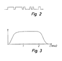
- the signal is weighted such that a uniform energy density is obtained across the desired bandwidth, cf. Fig. 3, from which it appears that said bandwidth is of a few MHz.
- Coincidence must apply to both phase and amplitude.
- This measuring signal is loaded in form of a digitized code into the RAM memory of DSP and is used during the reception for calculating the delay of the received signal. 128 samplings are involved of the transmitted and the received signal, respectively.
- the measuring signal is converted into analogous form in a so-called CODEC, for instance of the type AD-1849.
- this CODEC can also be used in connection with linear A/D-and D/A-converters 14 of 16 bit.
- One of these D/A-converters is used for generating the analogous measuring signal. After the level adjustment, the signal is transmitted to an output amplifier 10 for driving the loudspeaker 2.
- loudspeakers such as two loudspeakers in form of dometweeters with a horn, said loudspeakers being coupled by twos in series to their respective output amplifiers.
- said sources can optionally be phase--controlled.
- An electret microphone 4 can for instance be used as receiver.
- the microphone 4 is placed in the focal point of a parabolic reflector in order to obtain the highest possible directivity and a strong attenuation of a direct coupling from the loudspeaker 2.
- the microphone 4 communicates with a preamplifier 12.
- the preamplifier must present a good signal-noise-ratio and can for instance be of the type P0213 with an amplification of approximately 100.
- the A/D-conversion is also carried out in an A/D-1849. 16 bits are used in two channels.
- the sampling frequency is selected such that 256 samplings can be recorded during the period available from the transmission of a sound signal and until the echo is received.
- the conversion is initiated by means of DSP 6 after a suitable delay. This delay can be varied and adapted to the adjustment of the height of the cutting table of for instance a combine harvester.
- the echo from the surface of the ground is filtered by means of a mathematical function depending on the transfer function of the microphone and the surroundings.
- the filtered signal is then cross-correlated with the stored signal from the time of the transmission.
- the position of the maximum value of this correlation provides the delay of the sound signal.
- this delay must be supplemented with the delay originally set before the receiving of data for the echo. This sum is multiplied with half the velocity of the sound in air and represents then an expression of the distance between the measuring system and the surface of the ground.
- Fig. 4 shows an embodiment of a transducer arrangement with an array of transmitter transducers and one receiver transducer.
- the electronic circuit corresponds substantially to the one shown in Fig. 1.
- a DSP 6 is shown, which communicates via a bus 8 with the control computer of the combine harvester.
- DSP 6 communicates with an A/D-D/A- converter controlling a plurality of loudspeakers through some delay links ⁇ 1 t, ⁇ 2 t, ⁇ 3 t and ⁇ 4 t.
- the delays can be individually varied. Only one receiver is shown.
- the signal to the said loudspeakers is emitted by DSP.
- the signals emitted by the loudspeaker and reflected by the surface of the ground are received at the receiver 4.
- the varying of the delays renders is possible to focus on specific distances.
- the resulting advantage is that it is possible -to perform a check at a specific expected depth and thereby to suppress irrelevant noise, such as noise from the cutting table, which is very noisy
- the illustrated embodiment comprises only one receiver. None, however, prevents you from including several receivers.
- Transducer arrangements with several transmitter transducers are, however, preferred because it is thereby possible to release the highest possible amount of sound energy and thereby to obtain the best possible signal-noise-ratio.
- a transducer arrangement with several transmitter transducers and several receiver transducers is, however, also possible.
- the transmitter transducers in question must, however, be identical, and the receiver transducers in question must also be identical.
Landscapes
- Engineering & Computer Science (AREA)
- Radar, Positioning & Navigation (AREA)
- Remote Sensing (AREA)
- Physics & Mathematics (AREA)
- Computer Networks & Wireless Communication (AREA)
- General Physics & Mathematics (AREA)
- Acoustics & Sound (AREA)
- Environmental Sciences (AREA)
- Life Sciences & Earth Sciences (AREA)
- Measurement Of Velocity Or Position Using Acoustic Or Ultrasonic Waves (AREA)
- Finish Polishing, Edge Sharpening, And Grinding By Specific Grinding Devices (AREA)
- Harvester Elements (AREA)
- Length Measuring Devices Characterised By Use Of Acoustic Means (AREA)
- Processing Of Stones Or Stones Resemblance Materials (AREA)
- Mechanical Treatment Of Semiconductor (AREA)
- Constituent Portions Of Griding Lathes, Driving, Sensing And Control (AREA)
Applications Claiming Priority (3)
| Application Number | Priority Date | Filing Date | Title |
|---|---|---|---|
| DK009896A DK9896A (da) | 1996-01-30 | 1996-01-30 | Fremgangsmåde til måling af skærebordshøjde |
| DK9896 | 1996-01-30 | ||
| PCT/DK1997/000039 WO1997028461A1 (en) | 1996-01-30 | 1997-01-29 | Method and device for measuring the height of the cutting table |
Publications (2)
| Publication Number | Publication Date |
|---|---|
| EP0879427A1 EP0879427A1 (en) | 1998-11-25 |
| EP0879427B1 true EP0879427B1 (en) | 1999-12-01 |
Family
ID=8089715
Family Applications (1)
| Application Number | Title | Priority Date | Filing Date |
|---|---|---|---|
| EP97902154A Expired - Lifetime EP0879427B1 (en) | 1996-01-30 | 1997-01-29 | Method and device for measuring the height of the cutting table |
Country Status (12)
| Country | Link |
|---|---|
| US (1) | US6173614B1 (da) |
| EP (1) | EP0879427B1 (da) |
| AT (1) | ATE187255T1 (da) |
| AU (1) | AU1590797A (da) |
| BR (1) | BR9707476A (da) |
| CA (1) | CA2242520A1 (da) |
| CZ (1) | CZ236898A3 (da) |
| DE (1) | DE69700876T2 (da) |
| DK (1) | DK9896A (da) |
| HU (1) | HUP9901592A3 (da) |
| PL (1) | PL327832A1 (da) |
| WO (1) | WO1997028461A1 (da) |
Families Citing this family (3)
| Publication number | Priority date | Publication date | Assignee | Title |
|---|---|---|---|---|
| DE19739848A1 (de) * | 1997-09-11 | 1999-03-18 | Bosch Gmbh Robert | Brennkraftmaschine insbesondere für ein Kraftfahrzeug |
| DE19802724A1 (de) | 1998-01-24 | 1999-07-29 | Bosch Gmbh Robert | Überwachungseinrichtung für Signal-Echo-Sensoren |
| US6615570B2 (en) | 2001-06-28 | 2003-09-09 | Deere & Company | Header position control with forward contour prediction |
Family Cites Families (7)
| Publication number | Priority date | Publication date | Assignee | Title |
|---|---|---|---|---|
| US4738137A (en) * | 1986-06-12 | 1988-04-19 | The United States Of America As Represented By The Administrator, National Aeronautics And Space Administration | Acoustic emission frequency discrimination |
| GB8718717D0 (en) * | 1987-08-07 | 1987-09-16 | Sonin Inc | Measuring distances |
| US5060205A (en) * | 1990-05-29 | 1991-10-22 | Deere & Company | Ultrasonic distance measuring system |
| US5155983A (en) * | 1991-04-24 | 1992-10-20 | Ford New Holland, Inc. | Distance measurement and control using coded sonic signals |
| US5155984A (en) * | 1991-04-24 | 1992-10-20 | Ford New Holland, Inc. | Implement height control |
| US5365442A (en) * | 1991-10-21 | 1994-11-15 | Thermedics, Inc. | Sonic ranging grade level controller |
| US5714687A (en) * | 1995-10-31 | 1998-02-03 | Dunegan; Harold L. | Transducer for measuring acoustic emission events |
-
1996
- 1996-01-30 DK DK009896A patent/DK9896A/da not_active Application Discontinuation
-
1997
- 1997-01-29 HU HU9901592A patent/HUP9901592A3/hu unknown
- 1997-01-29 CZ CZ982368A patent/CZ236898A3/cs unknown
- 1997-01-29 US US09/117,562 patent/US6173614B1/en not_active Expired - Fee Related
- 1997-01-29 BR BR9707476A patent/BR9707476A/pt not_active IP Right Cessation
- 1997-01-29 CA CA002242520A patent/CA2242520A1/en not_active Abandoned
- 1997-01-29 DE DE69700876T patent/DE69700876T2/de not_active Expired - Fee Related
- 1997-01-29 AU AU15907/97A patent/AU1590797A/en not_active Abandoned
- 1997-01-29 PL PL97327832A patent/PL327832A1/xx unknown
- 1997-01-29 EP EP97902154A patent/EP0879427B1/en not_active Expired - Lifetime
- 1997-01-29 AT AT97902154T patent/ATE187255T1/de not_active IP Right Cessation
- 1997-01-29 WO PCT/DK1997/000039 patent/WO1997028461A1/en not_active Ceased
Also Published As
| Publication number | Publication date |
|---|---|
| DK9896A (da) | 1997-07-31 |
| CZ236898A3 (cs) | 1998-11-11 |
| DE69700876T2 (de) | 2000-06-29 |
| DE69700876D1 (de) | 2000-01-05 |
| CA2242520A1 (en) | 1997-08-07 |
| EP0879427A1 (en) | 1998-11-25 |
| WO1997028461A1 (en) | 1997-08-07 |
| US6173614B1 (en) | 2001-01-16 |
| AU1590797A (en) | 1997-08-22 |
| PL327832A1 (en) | 1999-01-04 |
| ATE187255T1 (de) | 1999-12-15 |
| HUP9901592A3 (en) | 1999-11-29 |
| HUP9901592A2 (hu) | 1999-08-30 |
| BR9707476A (pt) | 1999-04-06 |
Similar Documents
| Publication | Publication Date | Title |
|---|---|---|
| US6622560B2 (en) | Ultrasound imaging method and apparatus based on pulse compression technique using a spread spectrum signal | |
| US4270191A (en) | Doppler current meter for use at great depths | |
| CN113030982B (zh) | 双频超高分辨率测深侧扫声纳系统 | |
| JPS6224747B2 (da) | ||
| US7106657B2 (en) | Digital sounder module and method for detecting | |
| JP2003079623A (ja) | 超音波撮像システム及び超音波撮像方法 | |
| CN106814360A (zh) | 一种基于线性调频信号的多波束测深系统 | |
| JPH11235341A5 (da) | ||
| NO20022630D0 (no) | Fremgangsmåte for svekking av ekko, samt anordning | |
| EP0879427B1 (en) | Method and device for measuring the height of the cutting table | |
| GB2621964A (en) | An acoustic phased array system and method for determining well integrity in multi-string configurations | |
| JP2000249760A (ja) | 埋没物体探知ソーナーシステムおよびその探知方法 | |
| JP2543610B2 (ja) | 海底反射波位置検出装置 | |
| JP4892177B2 (ja) | デジタル測深機モジュール及び検知方法 | |
| JP4771790B2 (ja) | デジタルrfメモリ装置 | |
| JP2883679B2 (ja) | 超音波反射強度測定装置 | |
| JPH11264873A (ja) | 物体計測装置 | |
| JP3576890B2 (ja) | ソーナー装置 | |
| JP2880787B2 (ja) | 方向性聴音装置 | |
| JP2790906B2 (ja) | パッシブソーナの広帯域信号受信方法 | |
| JP3527792B2 (ja) | 水中探査装置 | |
| JPS6118464Y2 (da) | ||
| JPH0772242A (ja) | アクティブソナー装置 | |
| JPH0583154B2 (da) | ||
| JPH08152467A (ja) | 水中音源方向検出装置 |
Legal Events
| Date | Code | Title | Description |
|---|---|---|---|
| PUAI | Public reference made under article 153(3) epc to a published international application that has entered the european phase |
Free format text: ORIGINAL CODE: 0009012 |
|
| 17P | Request for examination filed |
Effective date: 19980715 |
|
| AK | Designated contracting states |
Kind code of ref document: A1 Designated state(s): AT BE CH DE DK ES FI FR GB GR IE IT LI NL PT SE |
|
| AX | Request for extension of the european patent |
Free format text: AL PAYMENT 980715;LT PAYMENT 980715;LV PAYMENT 980715;SI PAYMENT 980715 |
|
| GRAG | Despatch of communication of intention to grant |
Free format text: ORIGINAL CODE: EPIDOS AGRA |
|
| 17Q | First examination report despatched |
Effective date: 19981223 |
|
| GRAG | Despatch of communication of intention to grant |
Free format text: ORIGINAL CODE: EPIDOS AGRA |
|
| GRAG | Despatch of communication of intention to grant |
Free format text: ORIGINAL CODE: EPIDOS AGRA |
|
| GRAH | Despatch of communication of intention to grant a patent |
Free format text: ORIGINAL CODE: EPIDOS IGRA |
|
| GRAH | Despatch of communication of intention to grant a patent |
Free format text: ORIGINAL CODE: EPIDOS IGRA |
|
| GRAA | (expected) grant |
Free format text: ORIGINAL CODE: 0009210 |
|
| AK | Designated contracting states |
Kind code of ref document: B1 Designated state(s): AT BE CH DE DK ES FI FR GB GR IE IT LI NL PT SE |
|
| AX | Request for extension of the european patent |
Free format text: AL PAYMENT 19980715;LT PAYMENT 19980715;LV PAYMENT 19980715;SI PAYMENT 19980715 |
|
| LTIE | Lt: invalidation of european patent or patent extension | ||
| PG25 | Lapsed in a contracting state [announced via postgrant information from national office to epo] |
Ref country code: NL Free format text: LAPSE BECAUSE OF FAILURE TO SUBMIT A TRANSLATION OF THE DESCRIPTION OR TO PAY THE FEE WITHIN THE PRESCRIBED TIME-LIMIT Effective date: 19991201 Ref country code: LI Free format text: LAPSE BECAUSE OF FAILURE TO SUBMIT A TRANSLATION OF THE DESCRIPTION OR TO PAY THE FEE WITHIN THE PRESCRIBED TIME-LIMIT Effective date: 19991201 Ref country code: GR Free format text: LAPSE BECAUSE OF NON-PAYMENT OF DUE FEES Effective date: 19991201 Ref country code: CH Free format text: LAPSE BECAUSE OF FAILURE TO SUBMIT A TRANSLATION OF THE DESCRIPTION OR TO PAY THE FEE WITHIN THE PRESCRIBED TIME-LIMIT Effective date: 19991201 Ref country code: AT Free format text: LAPSE BECAUSE OF FAILURE TO SUBMIT A TRANSLATION OF THE DESCRIPTION OR TO PAY THE FEE WITHIN THE PRESCRIBED TIME-LIMIT Effective date: 19991201 |
|
| REF | Corresponds to: |
Ref document number: 187255 Country of ref document: AT Date of ref document: 19991215 Kind code of ref document: T |
|
| REG | Reference to a national code |
Ref country code: CH Ref legal event code: EP |
|
| PGFP | Annual fee paid to national office [announced via postgrant information from national office to epo] |
Ref country code: IE Payment date: 19991216 Year of fee payment: 4 |
|
| PGFP | Annual fee paid to national office [announced via postgrant information from national office to epo] |
Ref country code: SE Payment date: 19991220 Year of fee payment: 4 |
|
| REF | Corresponds to: |
Ref document number: 69700876 Country of ref document: DE Date of ref document: 20000105 |
|
| PGFP | Annual fee paid to national office [announced via postgrant information from national office to epo] |
Ref country code: ES Payment date: 20000111 Year of fee payment: 4 |
|
| REG | Reference to a national code |
Ref country code: IE Ref legal event code: FG4D |
|
| ITF | It: translation for a ep patent filed | ||
| PG25 | Lapsed in a contracting state [announced via postgrant information from national office to epo] |
Ref country code: PT Free format text: LAPSE BECAUSE OF FAILURE TO SUBMIT A TRANSLATION OF THE DESCRIPTION OR TO PAY THE FEE WITHIN THE PRESCRIBED TIME-LIMIT Effective date: 20000302 |
|
| ET | Fr: translation filed | ||
| NLV1 | Nl: lapsed or annulled due to failure to fulfill the requirements of art. 29p and 29m of the patents act | ||
| REG | Reference to a national code |
Ref country code: DK Ref legal event code: T3 |
|
| PG25 | Lapsed in a contracting state [announced via postgrant information from national office to epo] |
Ref country code: ES Free format text: LAPSE BECAUSE OF FAILURE TO SUBMIT A TRANSLATION OF THE DESCRIPTION OR TO PAY THE FEE WITHIN THE PRESCRIBED TIME-LIMIT Effective date: 20000614 |
|
| REG | Reference to a national code |
Ref country code: CH Ref legal event code: PL |
|
| PLBE | No opposition filed within time limit |
Free format text: ORIGINAL CODE: 0009261 |
|
| STAA | Information on the status of an ep patent application or granted ep patent |
Free format text: STATUS: NO OPPOSITION FILED WITHIN TIME LIMIT |
|
| 26N | No opposition filed | ||
| PG25 | Lapsed in a contracting state [announced via postgrant information from national office to epo] |
Ref country code: IE Free format text: LAPSE BECAUSE OF NON-PAYMENT OF DUE FEES Effective date: 20010129 |
|
| PG25 | Lapsed in a contracting state [announced via postgrant information from national office to epo] |
Ref country code: SE Free format text: LAPSE BECAUSE OF NON-PAYMENT OF DUE FEES Effective date: 20010131 |
|
| REG | Reference to a national code |
Ref country code: IE Ref legal event code: MM4A |
|
| REG | Reference to a national code |
Ref country code: GB Ref legal event code: IF02 |
|
| PGFP | Annual fee paid to national office [announced via postgrant information from national office to epo] |
Ref country code: FR Payment date: 20020211 Year of fee payment: 6 |
|
| PGFP | Annual fee paid to national office [announced via postgrant information from national office to epo] |
Ref country code: FI Payment date: 20020213 Year of fee payment: 6 Ref country code: DK Payment date: 20020213 Year of fee payment: 6 |
|
| PGFP | Annual fee paid to national office [announced via postgrant information from national office to epo] |
Ref country code: GB Payment date: 20020220 Year of fee payment: 6 |
|
| PGFP | Annual fee paid to national office [announced via postgrant information from national office to epo] |
Ref country code: DE Payment date: 20020221 Year of fee payment: 6 |
|
| PGFP | Annual fee paid to national office [announced via postgrant information from national office to epo] |
Ref country code: BE Payment date: 20020308 Year of fee payment: 6 |
|
| PG25 | Lapsed in a contracting state [announced via postgrant information from national office to epo] |
Ref country code: GB Free format text: LAPSE BECAUSE OF NON-PAYMENT OF DUE FEES Effective date: 20030129 Ref country code: FI Free format text: LAPSE BECAUSE OF NON-PAYMENT OF DUE FEES Effective date: 20030129 |
|
| PG25 | Lapsed in a contracting state [announced via postgrant information from national office to epo] |
Ref country code: DK Free format text: LAPSE BECAUSE OF NON-PAYMENT OF DUE FEES Effective date: 20030131 Ref country code: BE Free format text: LAPSE BECAUSE OF NON-PAYMENT OF DUE FEES Effective date: 20030131 |
|
| PG25 | Lapsed in a contracting state [announced via postgrant information from national office to epo] |
Ref country code: DE Free format text: LAPSE BECAUSE OF NON-PAYMENT OF DUE FEES Effective date: 20030801 |
|
| REG | Reference to a national code |
Ref country code: DK Ref legal event code: EBP |
|
| GBPC | Gb: european patent ceased through non-payment of renewal fee | ||
| PG25 | Lapsed in a contracting state [announced via postgrant information from national office to epo] |
Ref country code: FR Free format text: LAPSE BECAUSE OF NON-PAYMENT OF DUE FEES Effective date: 20030930 |
|
| REG | Reference to a national code |
Ref country code: FR Ref legal event code: ST |
|
| PG25 | Lapsed in a contracting state [announced via postgrant information from national office to epo] |
Ref country code: IT Free format text: LAPSE BECAUSE OF NON-PAYMENT OF DUE FEES Effective date: 20050129 |