EP0879181B1 - Vorrichtung zur durchflusssteuerung und mit einer solchen vorrichtung versehener behälter - Google Patents
Vorrichtung zur durchflusssteuerung und mit einer solchen vorrichtung versehener behälter Download PDFInfo
- Publication number
- EP0879181B1 EP0879181B1 EP96940682A EP96940682A EP0879181B1 EP 0879181 B1 EP0879181 B1 EP 0879181B1 EP 96940682 A EP96940682 A EP 96940682A EP 96940682 A EP96940682 A EP 96940682A EP 0879181 B1 EP0879181 B1 EP 0879181B1
- Authority
- EP
- European Patent Office
- Prior art keywords
- location
- duct
- flow
- barrier
- container
- Prior art date
- Legal status (The legal status is an assumption and is not a legal conclusion. Google has not performed a legal analysis and makes no representation as to the accuracy of the status listed.)
- Expired - Lifetime
Links
- 239000007788 liquid Substances 0.000 claims abstract description 60
- 230000004888 barrier function Effects 0.000 claims abstract description 28
- 239000002775 capsule Substances 0.000 claims abstract description 15
- 238000004891 communication Methods 0.000 claims abstract description 7
- 230000001186 cumulative effect Effects 0.000 claims abstract 2
- 235000013361 beverage Nutrition 0.000 description 8
- 239000000463 material Substances 0.000 description 6
- 235000013334 alcoholic beverage Nutrition 0.000 description 4
- 238000004519 manufacturing process Methods 0.000 description 4
- 229920003023 plastic Polymers 0.000 description 4
- 239000000047 product Substances 0.000 description 4
- 239000003921 oil Substances 0.000 description 3
- 239000004033 plastic Substances 0.000 description 3
- 239000000654 additive Substances 0.000 description 1
- 235000013532 brandy Nutrition 0.000 description 1
- 238000006073 displacement reaction Methods 0.000 description 1
- -1 duct 22 and a second Substances 0.000 description 1
- 230000000694 effects Effects 0.000 description 1
- 239000000686 essence Substances 0.000 description 1
- 238000005429 filling process Methods 0.000 description 1
- 239000000796 flavoring agent Substances 0.000 description 1
- 229920002457 flexible plastic Polymers 0.000 description 1
- 235000013531 gin Nutrition 0.000 description 1
- 238000007689 inspection Methods 0.000 description 1
- 235000021056 liquid food Nutrition 0.000 description 1
- 239000012263 liquid product Substances 0.000 description 1
- 239000000314 lubricant Substances 0.000 description 1
- 239000010687 lubricating oil Substances 0.000 description 1
- 239000002184 metal Substances 0.000 description 1
- 238000000034 method Methods 0.000 description 1
- 235000019520 non-alcoholic beverage Nutrition 0.000 description 1
- 230000037452 priming Effects 0.000 description 1
- 238000007789 sealing Methods 0.000 description 1
- 238000000926 separation method Methods 0.000 description 1
- 230000002459 sustained effect Effects 0.000 description 1
- 235000015041 whisky Nutrition 0.000 description 1
Images


Classifications
-
- B—PERFORMING OPERATIONS; TRANSPORTING
- B65—CONVEYING; PACKING; STORING; HANDLING THIN OR FILAMENTARY MATERIAL
- B65D—CONTAINERS FOR STORAGE OR TRANSPORT OF ARTICLES OR MATERIALS, e.g. BAGS, BARRELS, BOTTLES, BOXES, CANS, CARTONS, CRATES, DRUMS, JARS, TANKS, HOPPERS, FORWARDING CONTAINERS; ACCESSORIES, CLOSURES, OR FITTINGS THEREFOR; PACKAGING ELEMENTS; PACKAGES
- B65D49/00—Arrangements or devices for preventing refilling of containers
Definitions
- This invention relates to a flow control device and to a container provided therewith. It is particularly concerned with such a device for use with a liquid container such as a bottle.
- UK Patent 694389 shows a liquid dispensing closure for the neck of a vessel comprising a stopper arranged to be held against or in the neck of the vessel by a capsule fitting tightly around both the stopper and a part of reduced diameter on the neck, a pair of independent passages of substantially uniform cross section in the material of the stopper, each passage terminating on the bottom of the stopper in independent free communication with the interior of the vessel and near the top of the stopper in independent free access to the outside by way of a common orifice in the side of the capsule, the arrangement being such that when the neck of the vessel is lower than the bottom, one of the passages is in the form of a normal syphon with a priming part reaching from the interior of the vessel to the end of the shorter leg of the syphon while the other passage includes in series from the interior of the vessel an orifice of smaller cross section than the remainder of the passage and an in
- US PATENT 4 523 687 (Hullihen ) describes a non-refillable pour spout for use in the neck of a bottle for permitting liquid to be poured through said spout from within said bottle but resisting replenishment of the liquid of the liquid in said bottle, comprising: a generally cylindrical spout member having a top and bottom and adapted to fit sealingly within the neck of the bottle; a liquid pouring duct extending through said spout body member and including discharge tube means for defining a liquid discharge opening adjacent the top of said spout body member; a first check valve located in said pouring duct in said spout body member, including a first valve seat and a movable first valve closure body held within said spout body upwardly adjacent said first valve seat, said first check valve communicating with said discharge tube means; a second check valve located in said liquid pouring duct in said spout body member, including a second valve seat and a movable second valve closure body held within said spout body
- the preamble of claim 1 is based on this prior art.
- a flow control flow device comprising a body member for mounting the device in a container the body member defining thereon a first location and a second location; a first duct extending through the body member from the first location to the second location, the first duct having a first cross section and a first length; a second air duct extending through the body member from the second location to the first location the second duct having a second cross section and a second length; the relationship between the first cross section and first length of the first duct, and the second cross section and second length of the second duct being such as to offer: relatively low impedance to flow of liquid along the first duct from the first location to the second location and a consequent flow of air along the second duct from the second location to the first location; and relatively high impedance to flow of liquid along the first duct from the second location to the first location with a consequent flow of air along the second duct from the first location to the second location; the body member has a longitudinal axis and includes a barrier
- the body member or the barrier serves to locate a baffle in a flow path from the first location to the vicinity of the flow inlet so that liquid from the first location downstream of the baffle is caused to be deflected by the baffle so as not to enter the flow inlet directly from the flow path.
- the barrier is in the form of a cup shaped component having a base region, wall extending from the base region to provide an internal volume the cup shaped component having an open top ; a major proportion of the length of the first duct extending through the internal volume.
- the body member has an external sleeve comprising one or more deformable members located about the axis and adapted to resiliently conform to a port into or out of a container so as to inhibit the passage of liquid or air into or out of the container by way of the port except through their respective first or second ducts.
- the or each deformable member comprises an annular ring.
- the body member or the barrier or an extension thereof serves to locate a pouring lip in a flow path from the flow outlet to the second location.
- the lip comprises an annular member co-axial with the axis .
- a container having a duct through which liquid can be caused to pass into or out of the container characterised by the duct incorporating a flow control device according to the first aspect or any preferred version thereof.
- a closure for the container as claimed comprising a capsule for forming around the container to close off the duct, the capsule serving to incorporate the control device.
- Plug 11 is of transparent plastics material with a degree of flexibility and has an inner end 12 and an outer end 13. Cylindrical wall 14 provides for the secure location of the device 11 in the neck of a bottle as shown in Figure 3.
- the plug 11 has extending through it a first duct 15 for liquid and a second duct 16 for air.
- First duct 15 is of circular cross section with diameter D and is of length L.
- the first duct 15 incorporates a change in direction provided by angularity 15A which serve to inhibit attempt to pass a flexible tube through the plug 11.
- Second duct 16 is of circular cross section with diameter d and length l .
- Diameter d of second duct 16 is substantially less than diameter D of first duct 15.
- Length l of the second duct 16 is longer than length L of first duct 15 since it passes through the main body of plug 11 but also through stub extension 17 integral with plug 11.
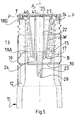
- Figure 3 shows a bottle 30 with neck 31 in which is incorporated plug 11 as described in connection with Figures 1 and 2.
- the bottle 30 contains a liquid beverage 31.
- To obtain a supply of beverage 31 the bottle is tipped to enable the liquid to flow along neck 31.
- the liquid enters the plug 11, passes through it by way of first duct 15 and leaves the bottle.
- the change in liquid volume of beverage 31 in the bottle 30 causes a consequent fall in pressure in the interior of the bottle 30 which is compensated for by an inflow of air into the bottle 30 by way of second duct 16.
- the relative sizes of the first duct 15 and the second duct 16 provide for the combination of the two to act as a form of diode to liquid flow.
- the combination of the two ducts provides little impedance to flow. It is a widespread illegal practice to attempt to refill a bottle when it has been emptied to a greater or lesser extent of an original authorised content so as to attempt to pass off the refilled liquid as being the same as an original contents. This is particularly widely practised when the original contents of the bottle was an imported expensive spirit such as whisky, gin or brandy and the bottle continues to bear its original label and/or other indicia.
- One common method of undertaking this form of counterfeiting is to immerse a conventional bottle in a reservoir of unoriginal liquid to enable the bottle to swiftly be refilled and thereafter the bottle is re-used.
- the diode effect referred to earlier acts to resist the refilling of the bottle.
- the relative proportions of the first duct 15 and the second duct 16 act to resist liquid flow through the plug 11 from the outer end 13 to the inner end 12 to a greater extent than was the case with flow in the other direction. It appears that any transfer of liquid into the bottle is initially very slow and soon ceases.
- the discontinuity 15A acts to limit travel or causes the tube to so distort that it cannot readily allow liquid to be entered into the bottle by way of the tube.
- the plug 11 In use the plug 11 will be installed in a bottle in the bottling plant serving to fill the bottles. Once inserted the plug 11 is not readily withdrawn.
- the device 16 is made up of body member 17 with a central longitudinal axis A.
- the body member 17 incorporates a barrier in the form of a cup with a base B, frusto conical side wall W and an top perimeter T which forms a lip section to facilitate the pouring a controlled stream of beverage from the bottle 11 especially when the bottle is only part filled.
- the body member 17 is of relatively rigid plastics material is provided with a sleeve 18 of relatively soft plastics material and incorporates a sequence of integral annular rings 18A to 18G with tapered outer faces (typically outer face 19 of ring 18A) so that the device 16 can be driven into the bore 15 and jammed therein in the axial location shown.
- the use of a sequence of rings 18A to 18G of flexible plastics material enables the device 16 to be introduced into and then forced down into bore 15 in a readily adapted filling operation.
- the rings 18A to 18F provide for the device once inserted in the bore to be accommodated in the neck with a bore 15 having a profile varying substantially from cylindrical and without tight tolerancing of the bore being needed. Once inserted the device 16 cannot be removed with virtually destroying it.
- the device 16 is provided with a first, liquid, duct 22 and a second, air, duct 23.
- the first duct 22 extends from flow inlet end 24 within the bottle 11 through the base B of the barrier and up to plane P shared by top perimeter T where the first duct 22 opens to atmosphere by way of flow outlet 25 lying symmetrically transverse axis A.
- the second duct 23 extends from air inlet end 27 outside the bottle 11 downwardly through the base 18 of the barrier and opens into the bottle 11 by way of air outlet 28 which lies symmetrically transversely across axis A.
- the first duct 22 and the second 23 lie at an angle to axis A to provide for the liquid flow outlet 25 to lie co-axial with, though off-set from, air outlet 28. This has been found to provide for greater control of pouring liquid from the bottle 11.
- the first duct 22, second duct 23 and body member 17 are formed as an integral unit to facilitate manufacture. Amongst other features the relative dimensions and locations of the ducts 22, 23 provide for controlled flow of liquid from the bottle through the first duct 22 and a flow of air into the bottle to replace the displaced liquid.
- a further liquid flow control feature is provided by a baffle 30 located beneath the device 16 when located in the bore 15 as shown.
- the baffle 30 has lowerface 31 directed towards the interior of bottle 11; and upper face 32 directed towards the flow inlet end 24 of the first duct 22.
- the baffle 30 has outer edge 33 which provides for an annular flow passage between the baffle and the inner wall of the bottlein the vicinity of the device 16.
- the second duct 23 extends downwardly beneath the baffle 30 so that the baffle 30 is located between air outlet 28 and liquid inlet 24. To facilitate manufacture the second duct 23 is of minimum bore for a short length in the vicinity of the air outlet 28.
- the bottle 11 is shown with the device 16 secured in place by the capsule 13 in a known manner.
- This can be readily achieved in a conventional bottle filling and sealing line by holding the perimeter 20 of the device 16 in a recess 40 in a rigid disc 41 mounted in the capsule 13.
- the machine in the bottling line whereby the capsule is located on the bottle and compressed around the neck 12 can readily cope with the loading necessary to drive the device 16 home into the neck 12.
- the neck 12 is configured on its outer surface to receive the capsule and hold it in place against inadvertent axial or rotary displacement.
- the bottle 12 is provided with a recess 43 into which recessed ring 44 is driven.
- Region 45 of the capsule provides a deliberately weakened section of the capsule so that when the bottle 12 is to be opened relative twisting of the upper part 46 and lower part 47 of the capsule to be separated allowing for the use of upper part 46 as a screw cap for the bottle when in use.
- the disc 41 is separated from the device 16 to leave the rim 20 exposed and allow the ready pouring of a steady flow of liquid from the bottle.
- the device 16 From the point of view of pouring the device 16 provides a number of advantages.
- liquid is not dispensed from the bottle by way of the device 16 until axis a of the bottle 11 has been tilted from the vertical by about 90 degrees.
- the baffle 30 limits the ability of the contents of the bottle on being tilted, especially when half full or less, to surge towards and flow directly through liquid flow inlet end 24 of the first duct 22. Any moving liquid hitting the barrier 30 is constrained to flow around it so dissipating kinetic energy.
- the invention provides an economical and effective means for resisting counterfeiting of original liquids while being readily installed in a conventional filling plant. While the exemplary embodiments describes a container in the form of a bottle for a liquid comprising an alcoholic beverage the invention is capable of application towards many types of container apart from bottles, such as cans and containers of metal, plastics material or treated card, and for many types of liquid apart from alcoholic beverages such as non-alcoholic beverages and essences, flavourings liquid foods, oils (both edible and those intended for oils and lubricants for machinery) and additives.
- the invention provides for a liquid container which while providing for the ready dispensing of the contents resists the refilling of the bottles and in particular resists the ready introduction of bogus liquids.
- the present invention provides a device which is cheap to manufacture and readily adopted for existing bottling or container filling processes which provides resists illicit filling. Quite apart from its defensive function the invention also provides a closure through which a liquid can be readily dispensed in a controlled manner from a container equipped with the closure.
Landscapes
- Engineering & Computer Science (AREA)
- Mechanical Engineering (AREA)
- Closures For Containers (AREA)
- Filling Of Jars Or Cans And Processes For Cleaning And Sealing Jars (AREA)
- Details Of Rigid Or Semi-Rigid Containers (AREA)
- Paper (AREA)
- External Artificial Organs (AREA)
- Supply Of Fluid Materials To The Packaging Location (AREA)
- Devices And Processes Conducted In The Presence Of Fluids And Solid Particles (AREA)
- Feeding, Discharge, Calcimining, Fusing, And Gas-Generation Devices (AREA)
Claims (9)
- Strömungssteuervorrichtung, mit einem Körperelement zum Anbringen der Vorrichtung in einem Behälter, wobei das Körperelement an diesem eine erste Stelle und eine zweite Stelle definiert; mit einem ersten Flüssigkeitsausgießkanal (22), der sich von der ersten Stelle zu der zweiten Stelle durch das Körperelement hindurch erstreckt, wobei der erste Kanal (22) einen ersten Querschnitt und eine erste Länge aufweist; mit einem zweiten Lufteinlasskanal (23), der sich von der zweiten Stelle zu der ersten Stelle durch das Körperelement hindurch erstreckt, wobei der zweite Kanal (23) einen zweiten Querschnitt und eine zweite Länge aufweist;
wobei der kumulative Effekt der Beziehung zwischen dem ersten Querschnitt (D) und der ersten Länge (L) des ersten Kanals (22) und dem zweiten Querschnitt (d) und der zweiten Länge (I) des zweiten Kanals (23) derart ist, dass sich Folgendes erzielen lässt: ein retativ niedriger Widerstand gegen eine Strömung von Flüssigkeit entlang des ersten Kanals (22) von der ersten Stelle zu der zweiten Stelle und eine sich daraus ergebende Strömung von Luft entlang des zweiten Kanals (23) von der zweiten Stelle zu der ersten Stelle; sowie ein relativ hoher Widerstand gegen eine Strömung von Flüssigkeit entlang des ersten Kanals (22) von der zweiten Stelle zu der ersten Stelle mit einer sich daraus ergebenden Strömung von Luft entlang des zweiten Kanals (23) von der ersten Stelle zu der zweiten Stelle;
wobei das Körperelement (17) eine Längsachse (A) aufweist und mit einer Barriere (18, 19) versehen ist, die sich quer zu der Achse (A) erstreckt, um die erste Stelle auf der einen Seite der Barriere (18, 19) zur Verbindung mit dem Innenraum eines Behälters, dem die Vorrichtung zugeordnet ist, zu definieren und die zweite Stelle auf der anderen Seite der Barriere zur Verbindung mit der Außenseite eines Behälters der vorstehend genannten Art zu definieren;
wobei sich der erste Kanal (22) durch die Barriere (18, 19) hindurch erstreckt und an der ersten Stelle mit einem Strömungseinlass (24) versehen ist und an der zweiten Stelle mit einem Strömungsauslass (25) versehen ist; wobei der zweite Kanal (23) an der zweiten Stelle mit einem Lufteinlass (27) versehen ist und an der ersten Stelle mit einem Luftauslass (28) versehen ist;
wobei der Luftauslass (28) und der Strömungsauslass (25) auf der Achse (A) liegen; wobei sich der Luftauslass (28) in Richtung der Achse (A) weiter von der Barriere (18, 19) weg erstreckt als der Strömungseinlass (24); und
wobei sich der Strömungsauslass (25) in Richtung der Achse (A) weiter von der Barriere (18, 19) weg erstreckt als der Lufteinlass (27);
dadurch gekennzeichnet, dass der erste Kanal (22) und der zweite Kanal (23) keine beweglichen Teile zum Regulieren der Strömung durch die beiden Kanäle (22, 23) enthalten;
wobei der erste Kanal (22) einen relativ gleichmäßigen Querschnitt aufweist, so dass sich keine signifikante Änderung bei der Behinderung der Strömung zwischen dem Strömungseinlass (24) und dem Strömungsauslass (25) ergibt. - Strömungssteuervorrichtung nach Anspruch 1,
dadurch gekennzeichnet, dass das Körperelement (17) oder die Barriere (18, 19) dazu dient, eine Trennwand (30) in einem Strömungsweg von der ersten Stelle zu einem Bereich in der Nähe des Strömungseinlasses (24) festzulegen, so dass Flüssigkeit von der ersten Stelle stromabwärts von der Trennwand (30) durch die Trennwand derart abgelenkt wird, dass sie nicht direkt von dem Strömungsweg in den Strömungseinlass (24) eintritt. - Strömungssteuervorrichtung nach Anspruch 1 oder Anspruch 2,
dadurch gekennzeichnet, dass die Barriere (18, 19) in Form einer becherförmigen Komponente vorliegt, die einen Basisbereich (18) und eine sich von dem Basisbereich (18) weg erstreckende Wand (19) zur Schaffung eines Innenvolumens aufweist, wobei die becherförmige Komponente eine offene Oberseite (20) aufweist;
wobei ein Hauptteil der Länge des ersten Kanals (22) sich durch das Innenvolumen hindurch erstreckt. - Strömungssteuervorrichtung nach einem der vorausgehenden Ansprüche,
dadurch gekennzeichnet, dass das Körperelement (17) eine Außenhülse (18) aufweist, die ein oder mehrere verformbare Elemente (18A bis 19G) besitzt, die um die Achse (A) herum angeordnet sind und dazu ausgebildet sind, sich elastisch an eine Öffnung in den Behälter (11) hinein oder aus diesem heraus anzupassen, um die Passage von Flüssigkeit oder Luft in den Behälter (11) hinein oder aus diesem heraus über die Öffnung mit Ausnahme durch ihren jeweiligen ersten oder zweiten Kanal (22, 23) zu unterbinden. - Strömungssteuervorrichtung nach Anspruch 4,
dadurch gekennzeichnet, dass das oder jedes verformbare Element (18A bis 18G) einen kreisförmigen Ring aufweist. - Strömungssteuervorrichtung nach einem der Ansprüche 1 bis 5,
dadurch gekennzeichnet, dass das Körperelement (17) oder die Barriere ( 18, 19, 20) oder eine Verlängerung davon dazu dient, eine Gießlippe (20) in einem Strömungsweg von dem Strömungsauslass (25) zu der zweiten Stelle festzulegen. - Strömungssteuervorrichtung nach Anspruch 6,
dadurch gekennzeichnet, dass die Lippe (20) ein ringförmiges Element aufweist, das koaxial mit der Achse (A) ist. - Behälter mit einem Kanal, durch den Flüsigkeit in den Behälter hinein oder aus diesem heraus gegossen werden kann,
dadurch gekennzeichnet, dass in dem Kanal (12) eine Strömungssteuervorrichtung (16) nach einem der Ansprüche 1 bis 7 vorgesehen ist. - Verschluss für einen Behälter nach Anspruch 8,
gekennzeichnet durch eine Kapsel (13) zur Ausbildung um den Behälter (13) herum zum Absperren des Kanals, wobei die Kapsel zum Integrieren der Steuervorrichtung (16) in diese dient.
Applications Claiming Priority (5)
| Application Number | Priority Date | Filing Date | Title |
|---|---|---|---|
| GB9523359 | 1995-11-16 | ||
| GB9523359A GB2307461A (en) | 1995-11-16 | 1995-11-16 | Flow control method and device to prevent refilling of containers |
| GB9613306 | 1996-06-25 | ||
| GB9613306A GB2318110B (en) | 1996-06-25 | 1996-06-25 | Flow control device & containers equipped therewith |
| PCT/GB1996/002819 WO1997018140A1 (en) | 1995-11-16 | 1996-11-15 | Flow control method, device and a container provided therewith |
Publications (2)
| Publication Number | Publication Date |
|---|---|
| EP0879181A1 EP0879181A1 (de) | 1998-11-25 |
| EP0879181B1 true EP0879181B1 (de) | 2005-02-02 |
Family
ID=26308121
Family Applications (1)
| Application Number | Title | Priority Date | Filing Date |
|---|---|---|---|
| EP96940682A Expired - Lifetime EP0879181B1 (de) | 1995-11-16 | 1996-11-15 | Vorrichtung zur durchflusssteuerung und mit einer solchen vorrichtung versehener behälter |
Country Status (10)
| Country | Link |
|---|---|
| US (1) | US6012617A (de) |
| EP (1) | EP0879181B1 (de) |
| AT (1) | ATE288390T1 (de) |
| BR (1) | BR9611539A (de) |
| CA (1) | CA2237847A1 (de) |
| CZ (1) | CZ294733B6 (de) |
| DE (1) | DE69634304D1 (de) |
| ES (1) | ES2241007T3 (de) |
| PL (1) | PL326762A1 (de) |
| WO (1) | WO1997018140A1 (de) |
Families Citing this family (7)
| Publication number | Priority date | Publication date | Assignee | Title |
|---|---|---|---|---|
| EP0958341A1 (de) | 1996-12-31 | 1999-11-24 | The Procter & Gamble Company | Verdickte, hochwässrige, kostengünstige, flüssige reinigungszusammensetzungen mit aromatische tenside |
| US7275665B2 (en) * | 2000-12-14 | 2007-10-02 | Young John L | Vented fluid closure and container |
| US6779694B2 (en) | 2000-12-14 | 2004-08-24 | John L. Young | Vented fluid closure and container |
| WO2003106041A1 (en) * | 2002-06-13 | 2003-12-24 | Sergey Stanislavovich Morozov | Device for controlling the flow of a medium from the storage reservoir thereof |
| US7527165B2 (en) * | 2005-06-06 | 2009-05-05 | Brain Box Concepts, Inc. | Disposable beverage container with lid |
| US8245891B2 (en) * | 2009-03-13 | 2012-08-21 | Barproducts.com, Inc. | Pour spout with drip supressing feature |
| US8657157B2 (en) * | 2009-12-23 | 2014-02-25 | The Patrón Spirits Company | Bottle closure with pour spout and related methods |
Family Cites Families (8)
| Publication number | Priority date | Publication date | Assignee | Title |
|---|---|---|---|---|
| FR4362E (fr) * | 1905-07-12 | Hilaire Gerard | Système de bouchage pour empecher le remplissage frauduleux des récipients | |
| US1750591A (en) * | 1926-09-06 | 1930-03-11 | Hafermann Alfred | Closure for nonrefillable bottles |
| US2335634A (en) * | 1941-12-10 | 1943-11-30 | Eldon H Young | Bottle valve manufacture |
| GB694389A (en) * | 1950-03-31 | 1953-07-22 | Pierre Andre Favre | A fraud-proof liquid-dispensing stopper for all kinds of vessels |
| US4193524A (en) * | 1978-03-13 | 1980-03-18 | Fleming Thomas W | Dispensing device with two-way flow characteristic and half twist closure |
| US4523687A (en) * | 1984-10-29 | 1985-06-18 | John Hullihen | Non-refillable pourer |
| US4802610A (en) * | 1987-01-05 | 1989-02-07 | The Dow Chemical Company | Pour spout |
| US5628352A (en) * | 1992-07-24 | 1997-05-13 | Briggs & Stratton Corporation | Closable pour spout for fluid dispensing container |
-
1996
- 1996-11-15 ES ES96940682T patent/ES2241007T3/es not_active Expired - Lifetime
- 1996-11-15 US US09/068,825 patent/US6012617A/en not_active Expired - Fee Related
- 1996-11-15 EP EP96940682A patent/EP0879181B1/de not_active Expired - Lifetime
- 1996-11-15 BR BR9611539-4A patent/BR9611539A/pt not_active Application Discontinuation
- 1996-11-15 PL PL96326762A patent/PL326762A1/xx unknown
- 1996-11-15 CA CA002237847A patent/CA2237847A1/en not_active Abandoned
- 1996-11-15 WO PCT/GB1996/002819 patent/WO1997018140A1/en not_active Ceased
- 1996-11-15 CZ CZ19981513A patent/CZ294733B6/cs not_active IP Right Cessation
- 1996-11-15 AT AT96940682T patent/ATE288390T1/de not_active IP Right Cessation
- 1996-11-15 DE DE69634304T patent/DE69634304D1/de not_active Expired - Lifetime
Also Published As
| Publication number | Publication date |
|---|---|
| WO1997018140A1 (en) | 1997-05-22 |
| EP0879181A1 (de) | 1998-11-25 |
| US6012617A (en) | 2000-01-11 |
| BR9611539A (pt) | 1999-09-21 |
| CZ294733B6 (cs) | 2005-03-16 |
| ATE288390T1 (de) | 2005-02-15 |
| CA2237847A1 (en) | 1997-05-22 |
| CZ151398A3 (cs) | 1999-08-11 |
| PL326762A1 (en) | 1998-10-26 |
| ES2241007T3 (es) | 2005-10-16 |
| DE69634304D1 (de) | 2005-03-10 |
Similar Documents
| Publication | Publication Date | Title |
|---|---|---|
| ES2261945T3 (es) | Conjunto de cierre para recipiente de liquido. | |
| US7934624B2 (en) | Container closure for simultaneously pouring out two separate liquids with a specified quantitative ratio | |
| US5897037A (en) | Combination cap and dispensing spout assembly | |
| GB2508348A (en) | Valve on a pourer regulating discharge from a bottle | |
| EP0879181B1 (de) | Vorrichtung zur durchflusssteuerung und mit einer solchen vorrichtung versehener behälter | |
| US10815114B2 (en) | Effervescent liquid dispenser | |
| CN101233052A (zh) | 容器封闭组件 | |
| WO1983004082A1 (en) | Improved dispenser closure | |
| EP0180411B1 (de) | Das Wiederfüllen verhindernder Ausguss | |
| US3945540A (en) | Valvular liquid dispensing closure | |
| US4660744A (en) | Non-refillable fitment | |
| CA2888950A1 (en) | Container having a dispense indicator | |
| TR201807708T4 (tr) | Yağ ya da sirke gibi bir sıvı için kullanılması amaçlanan yeniden doldurulamayan bir kap için kapatma. | |
| US11548773B1 (en) | Multipurpose vented funnel | |
| EP0768275A1 (de) | Verbindungseinrichtung für das Adaptieren einer Dosiervorrichtung an einer Flasche | |
| CA2158645A1 (en) | A beverage container with means for frothing the beverage | |
| GB2343177A (en) | A flow control device | |
| GB2318110A (en) | Device preventing refilling of container | |
| WO2025165253A1 (en) | Sealing system for containers adapted for the transport and/or storage of liquids | |
| GB2307461A (en) | Flow control method and device to prevent refilling of containers | |
| KR20240054731A (ko) | 와인병 가스유출방지마개 | |
| EP0015743A1 (de) | Ausgussbefestigung und mit solch einer Ausgussbefestigung ausgerüstete nicht wieder zu füllende Vorrichtung | |
| KR100490947B1 (ko) | 재충전 방지용 마개장치 | |
| US2050168A (en) | Nonrefillable bottle | |
| US583442A (en) | Fredrick |
Legal Events
| Date | Code | Title | Description |
|---|---|---|---|
| PUAI | Public reference made under article 153(3) epc to a published international application that has entered the european phase |
Free format text: ORIGINAL CODE: 0009012 |
|
| AK | Designated contracting states |
Kind code of ref document: A1 Designated state(s): AT BE CH DE DK ES FI FR GB GR IE IT LI LU MC NL PT SE |
|
| 17P | Request for examination filed |
Effective date: 19980814 |
|
| 17Q | First examination report despatched |
Effective date: 20011030 |
|
| GRAP | Despatch of communication of intention to grant a patent |
Free format text: ORIGINAL CODE: EPIDOSNIGR1 |
|
| RTI1 | Title (correction) |
Free format text: FLOW CONTROL DEVICE AND CONTAINER PROVIDED THEREWITH |
|
| GRAS | Grant fee paid |
Free format text: ORIGINAL CODE: EPIDOSNIGR3 |
|
| GRAA | (expected) grant |
Free format text: ORIGINAL CODE: 0009210 |
|
| AK | Designated contracting states |
Kind code of ref document: B1 Designated state(s): AT BE CH DE DK ES FI FR GB GR IE IT LI LU MC NL PT SE |
|
| PG25 | Lapsed in a contracting state [announced via postgrant information from national office to epo] |
Ref country code: NL Free format text: LAPSE BECAUSE OF FAILURE TO SUBMIT A TRANSLATION OF THE DESCRIPTION OR TO PAY THE FEE WITHIN THE PRESCRIBED TIME-LIMIT Effective date: 20050202 Ref country code: LI Free format text: LAPSE BECAUSE OF FAILURE TO SUBMIT A TRANSLATION OF THE DESCRIPTION OR TO PAY THE FEE WITHIN THE PRESCRIBED TIME-LIMIT Effective date: 20050202 Ref country code: FI Free format text: LAPSE BECAUSE OF FAILURE TO SUBMIT A TRANSLATION OF THE DESCRIPTION OR TO PAY THE FEE WITHIN THE PRESCRIBED TIME-LIMIT Effective date: 20050202 Ref country code: CH Free format text: LAPSE BECAUSE OF FAILURE TO SUBMIT A TRANSLATION OF THE DESCRIPTION OR TO PAY THE FEE WITHIN THE PRESCRIBED TIME-LIMIT Effective date: 20050202 Ref country code: BE Free format text: LAPSE BECAUSE OF FAILURE TO SUBMIT A TRANSLATION OF THE DESCRIPTION OR TO PAY THE FEE WITHIN THE PRESCRIBED TIME-LIMIT Effective date: 20050202 Ref country code: AT Free format text: LAPSE BECAUSE OF FAILURE TO SUBMIT A TRANSLATION OF THE DESCRIPTION OR TO PAY THE FEE WITHIN THE PRESCRIBED TIME-LIMIT Effective date: 20050202 |
|
| REG | Reference to a national code |
Ref country code: GB Ref legal event code: FG4D |
|
| REG | Reference to a national code |
Ref country code: CH Ref legal event code: EP |
|
| REG | Reference to a national code |
Ref country code: IE Ref legal event code: FG4D |
|
| REF | Corresponds to: |
Ref document number: 69634304 Country of ref document: DE Date of ref document: 20050310 Kind code of ref document: P |
|
| PG25 | Lapsed in a contracting state [announced via postgrant information from national office to epo] |
Ref country code: SE Free format text: LAPSE BECAUSE OF FAILURE TO SUBMIT A TRANSLATION OF THE DESCRIPTION OR TO PAY THE FEE WITHIN THE PRESCRIBED TIME-LIMIT Effective date: 20050502 Ref country code: GR Free format text: LAPSE BECAUSE OF FAILURE TO SUBMIT A TRANSLATION OF THE DESCRIPTION OR TO PAY THE FEE WITHIN THE PRESCRIBED TIME-LIMIT Effective date: 20050502 Ref country code: DK Free format text: LAPSE BECAUSE OF FAILURE TO SUBMIT A TRANSLATION OF THE DESCRIPTION OR TO PAY THE FEE WITHIN THE PRESCRIBED TIME-LIMIT Effective date: 20050502 |
|
| PG25 | Lapsed in a contracting state [announced via postgrant information from national office to epo] |
Ref country code: DE Free format text: LAPSE BECAUSE OF FAILURE TO SUBMIT A TRANSLATION OF THE DESCRIPTION OR TO PAY THE FEE WITHIN THE PRESCRIBED TIME-LIMIT Effective date: 20050503 |
|
| REG | Reference to a national code |
Ref country code: GB Ref legal event code: 732E |
|
| NLV1 | Nl: lapsed or annulled due to failure to fulfill the requirements of art. 29p and 29m of the patents act | ||
| REG | Reference to a national code |
Ref country code: CH Ref legal event code: PL |
|
| REG | Reference to a national code |
Ref country code: ES Ref legal event code: FG2A Ref document number: 2241007 Country of ref document: ES Kind code of ref document: T3 |
|
| REG | Reference to a national code |
Ref country code: FR Ref legal event code: TP |
|
| PG25 | Lapsed in a contracting state [announced via postgrant information from national office to epo] |
Ref country code: MC Free format text: LAPSE BECAUSE OF NON-PAYMENT OF DUE FEES Effective date: 20051130 Ref country code: LU Free format text: LAPSE BECAUSE OF NON-PAYMENT OF DUE FEES Effective date: 20051130 |
|
| PLBE | No opposition filed within time limit |
Free format text: ORIGINAL CODE: 0009261 |
|
| STAA | Information on the status of an ep patent application or granted ep patent |
Free format text: STATUS: NO OPPOSITION FILED WITHIN TIME LIMIT |
|
| 26N | No opposition filed |
Effective date: 20051103 |
|
| ET | Fr: translation filed | ||
| PGFP | Annual fee paid to national office [announced via postgrant information from national office to epo] |
Ref country code: ES Payment date: 20070130 Year of fee payment: 11 |
|
| PGFP | Annual fee paid to national office [announced via postgrant information from national office to epo] |
Ref country code: IE Payment date: 20070131 Year of fee payment: 11 |
|
| PG25 | Lapsed in a contracting state [announced via postgrant information from national office to epo] |
Ref country code: PT Free format text: LAPSE BECAUSE OF NON-PAYMENT OF DUE FEES Effective date: 20050702 |
|
| PGFP | Annual fee paid to national office [announced via postgrant information from national office to epo] |
Ref country code: FR Payment date: 20071127 Year of fee payment: 12 |
|
| REG | Reference to a national code |
Ref country code: IE Ref legal event code: MM4A |
|
| PGFP | Annual fee paid to national office [announced via postgrant information from national office to epo] |
Ref country code: IT Payment date: 20080510 Year of fee payment: 12 |
|
| PG25 | Lapsed in a contracting state [announced via postgrant information from national office to epo] |
Ref country code: IE Free format text: LAPSE BECAUSE OF NON-PAYMENT OF DUE FEES Effective date: 20071115 |
|
| REG | Reference to a national code |
Ref country code: ES Ref legal event code: FD2A Effective date: 20071116 |
|
| PG25 | Lapsed in a contracting state [announced via postgrant information from national office to epo] |
Ref country code: ES Free format text: LAPSE BECAUSE OF NON-PAYMENT OF DUE FEES Effective date: 20071116 |
|
| PG25 | Lapsed in a contracting state [announced via postgrant information from national office to epo] |
Ref country code: IT Free format text: LAPSE BECAUSE OF NON-PAYMENT OF DUE FEES Effective date: 20081115 |
|
| REG | Reference to a national code |
Ref country code: FR Ref legal event code: ST Effective date: 20090731 |
|
| PGFP | Annual fee paid to national office [announced via postgrant information from national office to epo] |
Ref country code: GB Payment date: 20091211 Year of fee payment: 14 |
|
| GBPC | Gb: european patent ceased through non-payment of renewal fee |
Effective date: 20101115 |
|
| PG25 | Lapsed in a contracting state [announced via postgrant information from national office to epo] |
Ref country code: FR Free format text: LAPSE BECAUSE OF NON-PAYMENT OF DUE FEES Effective date: 20081130 |
|
| PG25 | Lapsed in a contracting state [announced via postgrant information from national office to epo] |
Ref country code: GB Free format text: LAPSE BECAUSE OF NON-PAYMENT OF DUE FEES Effective date: 20101115 |