EP0878278B1 - Method for breaking bundles of sheets along a predetermined break line - Google Patents
Method for breaking bundles of sheets along a predetermined break line Download PDFInfo
- Publication number
- EP0878278B1 EP0878278B1 EP19980303481 EP98303481A EP0878278B1 EP 0878278 B1 EP0878278 B1 EP 0878278B1 EP 19980303481 EP19980303481 EP 19980303481 EP 98303481 A EP98303481 A EP 98303481A EP 0878278 B1 EP0878278 B1 EP 0878278B1
- Authority
- EP
- European Patent Office
- Prior art keywords
- bundle
- break line
- portions
- clamping
- clamping means
- Prior art date
- Legal status (The legal status is an assumption and is not a legal conclusion. Google has not performed a legal analysis and makes no representation as to the accuracy of the status listed.)
- Expired - Lifetime
Links
- 238000000034 method Methods 0.000 title claims description 11
- 238000000926 separation method Methods 0.000 claims description 2
- 230000033001 locomotion Effects 0.000 description 18
- 239000000463 material Substances 0.000 description 7
- 230000000750 progressive effect Effects 0.000 description 6
- 238000004519 manufacturing process Methods 0.000 description 3
- 239000011087 paperboard Substances 0.000 description 3
- 230000000694 effects Effects 0.000 description 2
- 238000012986 modification Methods 0.000 description 2
- 230000004048 modification Effects 0.000 description 2
- 229920001875 Ebonite Polymers 0.000 description 1
- 239000002184 metal Substances 0.000 description 1
- 239000012858 resilient material Substances 0.000 description 1
- 239000002699 waste material Substances 0.000 description 1
Images



Classifications
-
- B—PERFORMING OPERATIONS; TRANSPORTING
- B26—HAND CUTTING TOOLS; CUTTING; SEVERING
- B26F—PERFORATING; PUNCHING; CUTTING-OUT; STAMPING-OUT; SEVERING BY MEANS OTHER THAN CUTTING
- B26F3/00—Severing by means other than cutting; Apparatus therefor
- B26F3/002—Precutting and tensioning or breaking
-
- B—PERFORMING OPERATIONS; TRANSPORTING
- B26—HAND CUTTING TOOLS; CUTTING; SEVERING
- B26D—CUTTING; DETAILS COMMON TO MACHINES FOR PERFORATING, PUNCHING, CUTTING-OUT, STAMPING-OUT OR SEVERING
- B26D7/00—Details of apparatus for cutting, cutting-out, stamping-out, punching, perforating, or severing by means other than cutting
- B26D7/18—Means for removing cut-out material or waste
- B26D7/1827—Means for removing cut-out material or waste by tearing
-
- Y—GENERAL TAGGING OF NEW TECHNOLOGICAL DEVELOPMENTS; GENERAL TAGGING OF CROSS-SECTIONAL TECHNOLOGIES SPANNING OVER SEVERAL SECTIONS OF THE IPC; TECHNICAL SUBJECTS COVERED BY FORMER USPC CROSS-REFERENCE ART COLLECTIONS [XRACs] AND DIGESTS
- Y10—TECHNICAL SUBJECTS COVERED BY FORMER USPC
- Y10T—TECHNICAL SUBJECTS COVERED BY FORMER US CLASSIFICATION
- Y10T225/00—Severing by tearing or breaking
- Y10T225/30—Breaking or tearing apparatus
- Y10T225/329—Plural breakers
-
- Y—GENERAL TAGGING OF NEW TECHNOLOGICAL DEVELOPMENTS; GENERAL TAGGING OF CROSS-SECTIONAL TECHNOLOGIES SPANNING OVER SEVERAL SECTIONS OF THE IPC; TECHNICAL SUBJECTS COVERED BY FORMER USPC CROSS-REFERENCE ART COLLECTIONS [XRACs] AND DIGESTS
- Y10—TECHNICAL SUBJECTS COVERED BY FORMER USPC
- Y10T—TECHNICAL SUBJECTS COVERED BY FORMER US CLASSIFICATION
- Y10T225/00—Severing by tearing or breaking
- Y10T225/30—Breaking or tearing apparatus
- Y10T225/35—Work-parting pullers [bursters]
- Y10T225/357—Relatively movable clamps
Definitions
- This invention relates to a method for breaking bundles of sheets along a predetermined break line and to a breaker. It has particular, but not exclusive application to separating connected portions of bundles of articulated sheets into separate stacks of product portions.
- die cutters may cut and slot each sheet of material so as to form a multiplicity of product portions of each sheet.
- the die cutter may cut each sheet of material such that three or more cartons, or carton tops, or other product portions may be produced from each sheet of paperboard, plastic or other sheet material.
- This practice allows substantial economics of manufacture by efficiently utilizing the maximum square foot area of each sheet of material and minimising the amount of waste portions of each sheet.
- Such sheets of material, having multiple product portions connected together by small connecting portions are hereafter sometimes referred to as "articulated" sheets as will be more fully explained.
- the present invention aims to reduce these problems.
- FR-A-2514296 discloses the features of the pre-characterising part of Claim 1.
- the present invention provides a method for breaking a bundle of sheets along a predetermined break line which extends across a width of said bundle, comprising:
- Fig. 1 schematically illustrates one articulated sheet 10 which, for example, may be one sheet of corrugated paperboard which has been die cut to form three connected tops 10A, 10B and 10C for containers.
- sheet 10 is purely an example, and is simplified for purposes of clarity.
- Tops 10A, 10B and 10C are connected to each other by relatively small connecting portions 12 remaining in cut-out slots 14 such that, when portions 12 are severed, sheet 10 is intended to produce three separate container tops 10A, 10B and 10C.
- Such articulated sheets are typically stacked together to form bundles, and the bundles are then sent to the breaker to separate them into three stacks of product portions 10A, 10B and 10C.
- Fig. 2 schematically illustrates one prior art method of breaking adjacent product portions of stacked articulated sheets.
- one portion 16 of the bundle is clamped by upper and lower clamps 18A-B, and the adjacent portion 20 of the bundle is clamped by upper and lower clamps 22A-B.
- Clamps 22A-B are then deflected downwardly as shown in order to perform the break between adjacent stacks of product portions.
- the top portions must be separated by a wider dimension such that more power is required.
- FIG. 3 the upper surfaces of product portions 24A-B are shown as clamped by upper clamps 26A-B, and it will be understood that lower clamps (not shown) are provided so as to clamp product portions 24A-B therebetween.
- upper and lower clamps 26B are forced linearly apart from upper and lower clamps 26A such that the connection portions 28 are pulled apart under purely tensile force. This tends to pull the fibres of the sheets and does not result in a clean severing.
- much greater force is required to pull the portions apart by tensile force alone since no tearing or severing force is present.
- the prior art breakers require excessive power requirements and often do not provide clean breaks, particularly for thick bundles or bundles having large widths and many connecting portions.
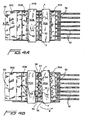
- FIG. 4A-4D The mode of operation of the breaker of the present invention is illustrated in schematic Figs. 4A-4D wherein the top articulated sheet 10 of a bundle 30 is illustrated in top plan view as in Fig. 1.
- bundle 30 has been moved in the direction of arrow A into the illustrated position in the breaker by a plurality of conveyor belts 32. Once in the illustrated position, the stack of product portions 30A is located below clamping member 40A and the stack of product portions 30B is located below clamping member 40B.
- each of clamping members 40A and 40B include a plurality of pads 42 which may be composed of metal, or preferably of a slightly resilient material such as hard rubber or plastic so as to prevent scuffing or denting of the upper and lowermost layers of the bundle.
- a second pair of clamping members 44A and 44B are located directly below clamping members 40A and 40B, respectively.
- the two stacks of product portions 30A and B are clamped therebetween when the upper and lower clamping members are moved vertically into firm clamping engagement with the uppermost and lowermost sheets of material comprising the bundle.
- the unique severing motion of the present invention comprises the following steps as illustrated in Figs. 4A-4D.
- bundle 30 has been securely clamped as just described, and it is to be understood that upper clamping member 40B and associated lower clamping member 44B remain in the same stationary position throughout the sequence of Figs. 4A-4D.
- upper clamping member 40A, and associated lower clamping member 44A are each mounted with two movable pivot points X and Y. Accordingly, pivot points X and Y are sometimes referred to hereafter as "floating" pivot points.
- pivot point X has remained stationary while pivot point Y has moved to the right in an arcuate path illustrated by arrow B.
- This arcuate motion of clamping members 40A and 44A about stationary pivot point X instantly and cleanly tears connecting portion 33 apart as edge 35 of stack 30A is forced away from edge 36 of stack 30B.
- the severing action is a progressive action on connecting portions 33 which begins at the point of the connecting portions which is closest to the edges 35, 36 of the stack, and this severing force then progress toward the opposite edge of the stack as the kerf progressively widens across the connecting portions 33 of the bundle.
- This mode of progressive severing substantially reduces the amount of force, and therefore power, which is required for breaking a stack of a given thickness. In addition, it produces cleaner breaks, and is extremely rapid.
- pivot point Y becomes fixed in the position shown in Fig. 4B.
- pivot point X is moved in an arcuate path shown by arrow C about pivot point Y.
- This produces a second, progressive severing action in the reverse direction; i.e. from edges 37, 38 across the width of the stack toward the center of the stack.
- This instantly tears connecting portions 34 such that stack 30A is fully severed from stacks 30B and C.
- connecting portions 34 such that stack 30A is fully severed from stacks 30B and C.
- connecting portions may be severed in the first arcuate movement illustrated in Fig. 4B followed by severing the remaining connection portions in the second arcuate movement and progressive severing action illustrated in Fig. 4C.
- first arcuate movement about pivot point X severs more than half of the connecting portions, such as 51% to 75% of the connecting portions, and the second arcuate movement about pivot point Y severs the remaining connecting portions.
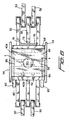
- the breaker of the present invention is preferably positioned between a feed conveyor 50 and a take-off conveyor 52. In between these two conveyors are positioned the plurality of side-by-side breaker conveyors 32 referred to previously. On either side of breaker conveyors 32 are provided a pair of vertically extending walls or other rigid and vertically extending support members 54. An upper support block 56 and a lower support block 58 of the breaker machine may be rigidly connected to supports 54.
- Upper support block 56 mounts a power cylinder 60 having an actuating rod 62
- lower support block 58 carries a power cylinder 64 having an actuating rod 66
- Upper rod 62 is rigidly connected to an upper carriage 68
- a lower rod 66 is rigidly connected to a lower carriage 70.
- Upper carriage 68 carries clamping member 40B including pads 42
- lower carriage 70 carries clamping member 44B and its pads 42 as previously described.
- Upper and lower clamping members 40B, 44B are rigidly connected to carriages 68, 70 and do not pivot as shown in Figs. 4A-C.
- Upper carriage 68 also carries clamping member 40A, such as in a horizontal slot 90
- lower carriage 70 carries clamping member 44A, such as in a similar horizontal slot 92.
- Engagement pads 42 may be connected to clamping members 40A and 44A by vertical rods or pins 94 which extend through vertical bores or slots 96 in the carriages.
- clamping members 40A, 44A may be raised and lowered by the carriages while also permitting the first and second pivoted movements of the clamping members as previously described.
- Figs. 5 and 6 illustrate four power cylinders 80, 82, 80' and 82'.
- Cylinders 80 and 80' are mounted on upper carriage 68 near the sides of the carriage as viewed in Fig. 6, and cylinders 82, 82' are mounted directly below cylinders 80, 80' on the lower carriage 70; cylinder 82' being hidden by cylinder 80' in Fig. 6.
- One of four actuating rods 86 extends horizontally from each of the power cylinders to one edge of one of clamping member 40A and 44A as shown in Figs. 5 and 6.
- pivotal connection Many forms of pivotal connection are possible, one of which is that the ends of the rods may be bent such as to form short vertical portions received in the clamping members. These vertical portions form floating pivot points X and Y for each of the upper clamping member 40A and lower clamping member 44A.
- individual horizontal movement of each rod 86 by its associated power cylinder enables the clamping members to execute the double-pivoted motion previously described.
- a proximity sensor 72 actuates one or more power cylinders or solenoids 74 to raise one or more stop members 76 upwardly between side-by-side conveyors 32. Accordingly, raised stop members 76 stop bundle 30 in the exact position shown in Fig. 5 wherein connecting portions 33 and 34 are midway between clamping members 40A and 40B.
- Power cylinder 64 is then actuated to raise lower carriage 70 and pads 42 above the board line of conveyors 32 so as to elevate the bundle above conveyors 32.
- conveyors 32 are stopped at this point.
- power cylinders 80' and 82' are not actuated such that the vertical ends of their associated rods are fixed and function as fixed pivot points X. Thereafter, as may be determined by a timer or position sensing means (not shown) power cylinders 80' and 82' are actuated and rods 86 move upper and lower clamping members 40A and 44A in the arcuate, progressively severing motion illustrated by arrow C in Fig. 4C.
- power cylinders 80 and 82 remain in their actuated position so as to hold pivot points Y in fixed position while pivot points X are moved in the arcuate path of arrow C and progressively sever connecting portions 34 from edges 37, 38 toward the center of the bundle as previously described with reference to Fig. 4C. Accordingly, stack 30A of the bundle is quickly and cleanly severed from stack 30B in two, arcuate and progressively severing motions which result in clean breaks with a minimum amount of energy.
- stop members 76 When first stack 30A has been broken, stop members 76 are dropped, and conveyors 32 move the bundle into the next position with stack 30B under member 40A and the steps are repeated while severed stack 30A is conveyed away from the breaking area as shown in Fig. 4D.
- the power cylinders be pneumatic, they may be hydraulic or electromagnetic.
- upper carriage 68 may be made fixed, and cylinder 60 may be eliminated, such that only lower carriage 70 is vertically movable to raise and clamp the bundle between the clamping members.
- Other modifications are apparent, such as mounting cylinder 80, 82, 80' and 82' on the opposite sides of clamping members 40A and 44B whereby rods 86 would be substantially shortened or eliminated.
- cylinders 80, 82, 80' and 82' may be mounted vertically; i.e., such that their operating rods move vertically, and a right angle drive providing a force multiplying effect may be used to convert the vertical motion to the horizontal motion as described.
- upper power cylinder 80 and lower power cylinder 82 could be extended and then retracted either partially or fully prior to actuating power cylinders 80' and 82'.
Landscapes
- Life Sciences & Earth Sciences (AREA)
- Forests & Forestry (AREA)
- Engineering & Computer Science (AREA)
- Mechanical Engineering (AREA)
- Sheets, Magazines, And Separation Thereof (AREA)
- Control And Other Processes For Unpacking Of Materials (AREA)
- Forming Counted Batches (AREA)
- Making Paper Articles (AREA)
- Crushing And Pulverization Processes (AREA)
Description
- This invention relates to a method for breaking bundles of sheets along a predetermined break line and to a breaker. It has particular, but not exclusive application to separating connected portions of bundles of articulated sheets into separate stacks of product portions.
- In the art of printing and die cutting sheets of material, such as corrugated paperboard for manufacturing containers, for example, it is well known that die cutters may cut and slot each sheet of material so as to form a multiplicity of product portions of each sheet. By way of a simplified example, the die cutter may cut each sheet of material such that three or more cartons, or carton tops, or other product portions may be produced from each sheet of paperboard, plastic or other sheet material. This practice allows substantial economics of manufacture by efficiently utilizing the maximum square foot area of each sheet of material and minimising the amount of waste portions of each sheet. Such sheets of material, having multiple product portions connected together by small connecting portions, are hereafter sometimes referred to as "articulated" sheets as will be more fully explained.
- After the articulated sheets have been die cut, which usually follows the printing of indicia on each sheet, pluralities of sheets are stacked in relatively short bundles, and the bundles are sent to a breaker in order to separate the bundles into separate stacks of product portions. This breaking of bundles into separate product portions has been a long-standing problem for many reasons. For example, the ultra-high speed printing and die cutting machines of the present day, which can process 5m/s (1000 ft/min) of sheets, require that the breaking function keep pace with the total production line. This requires that the number of sheets per bundle, and therefore, per "break", be increased over that previously possible, and the number of breaks per unit of time must be increased. Secondly, the break must be "clean" with no tears in the product portions. Furthermore, some connecting portions must not be broken along straight lines, but rather, along right angles and rounded connecting portions between product portions such as in the cases of "nested" or "lock bottom" sheets, respectively.
- The present invention aims to reduce these problems.
- FR-A-2514296 discloses the features of the pre-characterising part of Claim 1.
- The present invention provides a method for breaking a bundle of sheets along a predetermined break line which extends across a width of said bundle, comprising:
- (a) clamping a first portion of said bundle with a first set of clamping means on one side of said break line;
- (b) clamping a second portion of said bundle with a second set of clamping means on the other side of said break line;
- (c) holding said second set of clamping means stationary; and
- (d) moving said first set of clamping means away from said second set of clamping means so as to sever said bundle along said break line and thereby separate said first and second portions, characterised in that said first set of clamping means is pivoted about a first pivot point so as to sever said bundle progressively in a first direction along said break line until said first and second portions are partially separated, and then said first set of clamping means is pivoted about a second pivot point so as to sever said bundle progressively in the reverse direction along said break line, thereby completing the separation of said first and second portions.
-
- Further features are set out in Claims 2 to 5.
- For a better understanding of the present invention, and to show how the same may be carried into effect, reference will now be made, by way of example, to the accompanying drawings, in which:-
- Fig. 1 is a top plan view of one sample of articulated sheet;
- Fig. 2 is a schematic side view of one form of prior art breaker;
- Fig. 3 is a schematic top view of another form of prior art breaker;
- Fig. 4A-4D are schematic top views of the sequence of positions of a breaker of the present invention;
- Fig. 5 is a schematic side elevational view partly in cross-section of the breaker shown in Figs. 4A-4D; and
- Fig. 6 is a top plan view of the breaker of Fig. 5.
-
- Fig. 1 schematically illustrates one articulated
sheet 10 which, for example, may be one sheet of corrugated paperboard which has been die cut to form three connected tops 10A, 10B and 10C for containers. Of course, it will be understood thatsheet 10 is purely an example, and is simplified for purposes of clarity. Tops 10A, 10B and 10C are connected to each other by relatively small connectingportions 12 remaining in cut-outslots 14 such that, whenportions 12 are severed,sheet 10 is intended to produce three separate container tops 10A, 10B and 10C. Such articulated sheets are typically stacked together to form bundles, and the bundles are then sent to the breaker to separate them into three stacks of product portions 10A, 10B and 10C. - Fig. 2 schematically illustrates one prior art method of breaking adjacent product portions of stacked articulated sheets. In this method, one
portion 16 of the bundle is clamped by upper andlower clamps 18A-B, and theadjacent portion 20 of the bundle is clamped by upper andlower clamps 22A-B. Clamps 22A-B are then deflected downwardly as shown in order to perform the break between adjacent stacks of product portions. However, in order to separate the bottom-most layers of sheets, the top portions must be separated by a wider dimension such that more power is required. - In Fig. 3, the upper surfaces of
product portions 24A-B are shown as clamped byupper clamps 26A-B, and it will be understood that lower clamps (not shown) are provided so as to clampproduct portions 24A-B therebetween. In order to separateproduct portions 24B fromproduct portions 24A, upper and lower clamps 26B are forced linearly apart from upper andlower clamps 26A such that theconnection portions 28 are pulled apart under purely tensile force. This tends to pull the fibres of the sheets and does not result in a clean severing. In addition, much greater force is required to pull the portions apart by tensile force alone since no tearing or severing force is present. In summary, the prior art breakers require excessive power requirements and often do not provide clean breaks, particularly for thick bundles or bundles having large widths and many connecting portions. - The mode of operation of the breaker of the present invention is illustrated in schematic Figs. 4A-4D wherein the top articulated
sheet 10 of abundle 30 is illustrated in top plan view as in Fig. 1. As will be further described hereinafter,bundle 30 has been moved in the direction of arrow A into the illustrated position in the breaker by a plurality ofconveyor belts 32. Once in the illustrated position, the stack ofproduct portions 30A is located belowclamping member 40A and the stack ofproduct portions 30B is located belowclamping member 40B. Preferably, each of clampingmembers pads 42 which may be composed of metal, or preferably of a slightly resilient material such as hard rubber or plastic so as to prevent scuffing or denting of the upper and lowermost layers of the bundle. Of course, as will be more fully described hereinafter, a second pair ofclamping members members product portions 30A and B are clamped therebetween when the upper and lower clamping members are moved vertically into firm clamping engagement with the uppermost and lowermost sheets of material comprising the bundle. - The unique severing motion of the present invention comprises the following steps as illustrated in Figs. 4A-4D. In Fig. 4A,
bundle 30 has been securely clamped as just described, and it is to be understood thatupper clamping member 40B and associatedlower clamping member 44B remain in the same stationary position throughout the sequence of Figs. 4A-4D. However,upper clamping member 40A, and associatedlower clamping member 44A, are each mounted with two movable pivot points X and Y. Accordingly, pivot points X and Y are sometimes referred to hereafter as "floating" pivot points. - As shown in Fig. 4B, pivot point X has remained stationary while pivot point Y has moved to the right in an arcuate path illustrated by arrow B. This arcuate motion of clamping
members tears connecting portion 33 apart asedge 35 ofstack 30A is forced away fromedge 36 ofstack 30B. It will also be noted that the severing action is a progressive action on connectingportions 33 which begins at the point of the connecting portions which is closest to theedges portions 33 of the bundle. This mode of progressive severing substantially reduces the amount of force, and therefore power, which is required for breaking a stack of a given thickness. In addition, it produces cleaner breaks, and is extremely rapid. - After the first severing action as just described, pivot point Y becomes fixed in the position shown in Fig. 4B. Then, as shown in Fig. 4C, pivot point X is moved in an arcuate path shown by arrow C about pivot point Y. This produces a second, progressive severing action in the reverse direction; i.e. from
edges portions 34 such thatstack 30A is fully severed fromstacks 30B and C. Of course, it will be understood that in the simplified illustrations, only two sets of connecting or severingportions - Having described the unique severing motions of the present breaker in primarily functional terms, one illustrative example of one form of structure for accomplishing this unique function will now be described with reference to Figs. 5 and 6. The breaker of the present invention is preferably positioned between a
feed conveyor 50 and a take-offconveyor 52. In between these two conveyors are positioned the plurality of side-by-side breaker conveyors 32 referred to previously. On either side ofbreaker conveyors 32 are provided a pair of vertically extending walls or other rigid and vertically extendingsupport members 54. Anupper support block 56 and alower support block 58 of the breaker machine may be rigidly connected to supports 54.Upper support block 56 mounts apower cylinder 60 having an actuating rod 62, andlower support block 58 carries apower cylinder 64 having an actuatingrod 66. Upper rod 62 is rigidly connected to anupper carriage 68, and alower rod 66 is rigidly connected to alower carriage 70.Upper carriage 68carries clamping member 40B including pads 42, andlower carriage 70carries clamping member 44B and itspads 42 as previously described. Upper andlower clamping members carriages -
Upper carriage 68 also carries clampingmember 40A, such as in ahorizontal slot 90, andlower carriage 70carries clamping member 44A, such as in a similarhorizontal slot 92.Engagement pads 42 may be connected to clampingmembers slots 96 in the carriages. Of course, many other mounting arrangements are possible so long as clampingmembers - The means for causing clamping members to execute the pivotal movements may also take many forms and, solely for purposes of example, Figs. 5 and 6 illustrate four
power cylinders Cylinders 80 and 80' are mounted onupper carriage 68 near the sides of the carriage as viewed in Fig. 6, andcylinders 82, 82' are mounted directly belowcylinders 80, 80' on thelower carriage 70; cylinder 82' being hidden by cylinder 80' in Fig. 6. One of fouractuating rods 86 extends horizontally from each of the power cylinders to one edge of one of clampingmember upper clamping member 40A andlower clamping member 44A. Thus, individual horizontal movement of eachrod 86 by its associated power cylinder enables the clamping members to execute the double-pivoted motion previously described. - The overall operation of the breaker of the present invention is as follows. Referring first to Fig. 5, when a
bundle 30 has been conveyed into the breaker, the presence of its leading edge is detected by sensor means such as, for example, aproximity sensor 72.Sensor 72 actuates one or more power cylinders orsolenoids 74 to raise one ormore stop members 76 upwardly between side-by-side conveyors 32. Accordingly, raisedstop members 76stop bundle 30 in the exact position shown in Fig. 5 wherein connectingportions members 40A and40B. Power cylinder 64 is then actuated to raiselower carriage 70 andpads 42 above the board line ofconveyors 32 so as to elevate the bundle aboveconveyors 32. Preferably,conveyors 32 are stopped at this point. Alternately, they may continue to run since the bundle is raised above, and out of contact with, the conveyors at this point. Withbundle 30 elevated out of contact withconveyors 32,power cylinder 60 is energised so thatupper carriage 68 moves downwardly and itspads 42 engage and clamp the bundle securely. The bundle is then positioned and clamped for breaking in two progressive tearing movements as follows. In the first movement,upper power cylinder 80 andlower power cylinder 82 are actuated simultaneously. These cylinders simultaneously extend their associatedrods 86 so as to move pivot points Y ofmembers rods 86 move upper andlower clamping members power cylinders portions 34 fromedges stack 30B in two, arcuate and progressively severing motions which result in clean breaks with a minimum amount of energy. - When
first stack 30A has been broken, stopmembers 76 are dropped, andconveyors 32 move the bundle into the next position withstack 30B undermember 40A and the steps are repeated while severedstack 30A is conveyed away from the breaking area as shown in Fig. 4D. - From the foregoing description of one illustrative embodiment of the invention, it will be apparent that many modifications and alternative components will become obvious to those skilled in the art. For example, while it is preferred that the power cylinders be pneumatic, they may be hydraulic or electromagnetic. Also, if the thickness of the bundles to be processed are relatively constant,
upper carriage 68 may be made fixed, andcylinder 60 may be eliminated, such that onlylower carriage 70 is vertically movable to raise and clamp the bundle between the clamping members. Other modifications are apparent, such as mountingcylinder members rods 86 would be substantially shortened or eliminated. Alternatively,cylinders - If desired
upper power cylinder 80 andlower power cylinder 82 could be extended and then retracted either partially or fully prior to actuating power cylinders 80' and 82'.
Claims (5)
- A method for breaking a bundle of sheets (30) along a predetermined break line which extends across a width of said bundle, comprising:(a) clamping a first portion (30A) of said bundle with a first set of clamping means (40A, 44A) on one side of said break line;(b) clamping a second portion (30B) of said bundle with a second set of clamping means (40B, 44B) on the other side of said break line;(c) holding said second set of clamping means (40B, 44B) stationary; and(d) moving said first set of clamping means (40A, 44A) away from said second set of clamping means (40B, 44B) so as to sever said bundle along said break line and thereby separate said first and second portions,
characterised in that said first set of clamping means (40A, 44A) is pivoted about a first pivot point (x) so as to sever said bundle progressively in a first direction along said break line until said first and second portions are partially separated, and then said first set of clamping means (40A, 44A) is pivoted about a second pivot point (y) so as to sever said bundle progressively in the reverse direction along said break line, thereby completing the separation of said first and second portions. - A method according to Claim 1, in which said first pivot point (x) is located substantially at a first end of said break line.
- A method according to Claim 1 or 2, in which said second pivot point (y) is located substantially at a second end of said break line.
- A method according to any preceding claim, further comprising the step of conveying the bundle on a conveyor (50) to the point at which said bundle is broken.
- A method according to Claim 4, further comprising the step of lifting said bundle above said conveyor and breaking said bundle along said break line whilst above said conveyor.
Applications Claiming Priority (2)
| Application Number | Priority Date | Filing Date | Title |
|---|---|---|---|
| US848982 | 1997-05-02 | ||
| US08/848,982 US5865358A (en) | 1997-05-02 | 1997-05-02 | Breaker machine |
Publications (3)
| Publication Number | Publication Date |
|---|---|
| EP0878278A2 EP0878278A2 (en) | 1998-11-18 |
| EP0878278A3 EP0878278A3 (en) | 1999-11-03 |
| EP0878278B1 true EP0878278B1 (en) | 2003-10-08 |
Family
ID=25304777
Family Applications (1)
| Application Number | Title | Priority Date | Filing Date |
|---|---|---|---|
| EP19980303481 Expired - Lifetime EP0878278B1 (en) | 1997-05-02 | 1998-05-05 | Method for breaking bundles of sheets along a predetermined break line |
Country Status (3)
| Country | Link |
|---|---|
| US (1) | US5865358A (en) |
| EP (1) | EP0878278B1 (en) |
| DE (1) | DE69818741T2 (en) |
Families Citing this family (8)
| Publication number | Priority date | Publication date | Assignee | Title |
|---|---|---|---|---|
| US6427893B1 (en) * | 1999-10-05 | 2002-08-06 | Maryland Plastics, Inc. | Method and apparatus for degating plastic members from a runner |
| US6655566B1 (en) * | 2002-08-28 | 2003-12-02 | Martin Family Trust | Bundle breaker improvement |
| ES2284988T3 (en) * | 2003-02-04 | 2007-11-16 | Alfing Kessler Sondermaschinen Gmbh | PROCEDURE AND DEVICE FOR DIVIDING FRACTURE PARTS IN THE FORM OF A DISC OR PLATE. |
| ES2385097T3 (en) * | 2007-06-29 | 2012-07-18 | J&L Group International, Llc (Jlgi) | Apparatus and method for separating a stack of sheets from a stack of sheets |
| WO2010040069A1 (en) * | 2008-10-03 | 2010-04-08 | J & L Group International, Llc | Bundle breaker |
| US8342374B2 (en) * | 2009-02-11 | 2013-01-01 | Insight Promotions, Llc | Fragile premium separator |
| US8276797B2 (en) * | 2009-09-04 | 2012-10-02 | Insight Promotions, Llc | Premium separator with contoured spaced-apart belt |
| JP6999492B2 (en) * | 2018-05-22 | 2022-01-18 | レンゴー株式会社 | Sheet product splitter |
Family Cites Families (10)
| Publication number | Priority date | Publication date | Assignee | Title |
|---|---|---|---|---|
| US2171769A (en) * | 1938-05-06 | 1939-09-05 | Myer H Stolar | Sheet stripping and separating device |
| US2268190A (en) * | 1940-03-11 | 1941-12-30 | Robert J Copeland | Sheet separating device |
| BE792408A (en) * | 1971-12-22 | 1973-06-07 | Burroughs Corp | BREAKDOWN AND SEPARATION DEVICE FOR CONTINUOUS FORMS |
| US3780921A (en) * | 1972-06-16 | 1973-12-25 | Union Carbide Corp | Method and apparatus for producing gang of separably interconnected elongate articles |
| US4025023A (en) * | 1975-10-31 | 1977-05-24 | International Business Machines Corporation | Burster apparatus |
| JPS5326063A (en) * | 1976-06-14 | 1978-03-10 | Kurisuchian Bunderuritsuhi | Method and device for separating and piling sheets such as paper* thick paper* etc* |
| FR2514296A1 (en) * | 1981-10-12 | 1983-04-15 | Lucas Raymond | Separator for packaged pictures - has two compressing posts with detectors and two conveyor belts for reciprocation of one work post |
| CH646665A5 (en) * | 1982-05-19 | 1984-12-14 | Bobst Sa | DEVICE FOR SEPARATING FROM ONE ANOTHER THE DIFFERENT POSES OF A PACKET OF CUT SHEETS. |
| DE4113792C2 (en) * | 1991-04-26 | 1998-11-26 | Icoma Fbs Gmbh Packtechnik | Separating device for separating perforated paper tube sections |
| US5791539A (en) * | 1996-07-01 | 1998-08-11 | Thermoguard Equipment, Inc. | Bundle breaker |
-
1997
- 1997-05-02 US US08/848,982 patent/US5865358A/en not_active Expired - Fee Related
-
1998
- 1998-05-05 EP EP19980303481 patent/EP0878278B1/en not_active Expired - Lifetime
- 1998-05-05 DE DE1998618741 patent/DE69818741T2/en not_active Expired - Fee Related
Also Published As
| Publication number | Publication date |
|---|---|
| DE69818741T2 (en) | 2004-07-15 |
| EP0878278A2 (en) | 1998-11-18 |
| US5865358A (en) | 1999-02-02 |
| EP0878278A3 (en) | 1999-11-03 |
| DE69818741D1 (en) | 2003-11-13 |
Similar Documents
| Publication | Publication Date | Title |
|---|---|---|
| US4921154A (en) | Separating device in an automatic stamping machine | |
| US4995784A (en) | Process for breaking and removing a tie surrounding a bundle | |
| US4136604A (en) | Method and apparatus for separating individual blanks of a multiple cardboard blank | |
| EP0468374B1 (en) | Rotary shear | |
| US8240652B2 (en) | Method and apparatus for separating packages of interfolded sheets at high flexibility | |
| GB2210861A (en) | Carton blank deceleration unit | |
| EP1630118A1 (en) | Structure of interfolding machine | |
| US5829951A (en) | Collecting and stacking device for laminar sheets and stacking method | |
| US5865358A (en) | Breaker machine | |
| CN1235786C (en) | Method and device for perforating material bands | |
| US5156516A (en) | Device for breaking and removing a tie surrounding a bundle | |
| JP3159892B2 (en) | A movable upper tool for separating blanks from sheets processed by a package manufacturing press | |
| US5154689A (en) | Blank forming machine with a front waste removal device | |
| JPS62264168A (en) | Folding device for web material | |
| US5927582A (en) | Separator for stacked corrugated board | |
| WO2008129579A2 (en) | Improvements to a bundle breaker and method for its operation | |
| JPS63110000A (en) | Method and device for cutting zigzag folded material web | |
| CN108750774B (en) | Automatic paper stacking machine | |
| AU3359401A (en) | Device for transporting a flat section of a product | |
| US20100108732A1 (en) | Bundle breaker | |
| WO2003097340A1 (en) | Machine for manufacturing cardboard blanks | |
| KR100246834B1 (en) | Device for turning the front panel of a plate-like workpiece within a folder-gluer | |
| US5074835A (en) | Device for stacking and cutting a zigzag folded web | |
| US3889562A (en) | Installation for piece-by-piece throughput of rolled rubber sheets out of a cooling unit | |
| CN216708494U (en) | Paper pulp packaging product side cut equipment |
Legal Events
| Date | Code | Title | Description |
|---|---|---|---|
| PUAI | Public reference made under article 153(3) epc to a published international application that has entered the european phase |
Free format text: ORIGINAL CODE: 0009012 |
|
| AK | Designated contracting states |
Kind code of ref document: A2 Designated state(s): CH DE FR GB LI |
|
| AX | Request for extension of the european patent |
Free format text: AL;LT;LV;MK;RO;SI |
|
| PUAL | Search report despatched |
Free format text: ORIGINAL CODE: 0009013 |
|
| AK | Designated contracting states |
Kind code of ref document: A3 Designated state(s): AT BE CH CY DE DK ES FI FR GB GR IE IT LI LU MC NL PT SE |
|
| AX | Request for extension of the european patent |
Free format text: AL;LT;LV;MK;RO;SI |
|
| 17P | Request for examination filed |
Effective date: 20000221 |
|
| AKX | Designation fees paid |
Free format text: CH DE FR GB LI |
|
| 17Q | First examination report despatched |
Effective date: 20010403 |
|
| GRAG | Despatch of communication of intention to grant |
Free format text: ORIGINAL CODE: EPIDOS AGRA |
|
| RTI1 | Title (correction) |
Free format text: METHOD FOR BREAKING BUNDLES OF SHEETS ALONG A PREDETERMINED BREAK LINE |
|
| GRAG | Despatch of communication of intention to grant |
Free format text: ORIGINAL CODE: EPIDOS AGRA |
|
| GRAH | Despatch of communication of intention to grant a patent |
Free format text: ORIGINAL CODE: EPIDOS IGRA |
|
| GRAH | Despatch of communication of intention to grant a patent |
Free format text: ORIGINAL CODE: EPIDOS IGRA |
|
| GRAG | Despatch of communication of intention to grant |
Free format text: ORIGINAL CODE: EPIDOS AGRA |
|
| RAP1 | Party data changed (applicant data changed or rights of an application transferred) |
Owner name: WARD, INC. |
|
| GRAA | (expected) grant |
Free format text: ORIGINAL CODE: 0009210 |
|
| AK | Designated contracting states |
Kind code of ref document: B1 Designated state(s): CH DE FR GB LI |
|
| REG | Reference to a national code |
Ref country code: GB Ref legal event code: FG4D |
|
| REG | Reference to a national code |
Ref country code: CH Ref legal event code: EP |
|
| REG | Reference to a national code |
Ref country code: CH Ref legal event code: NV Representative=s name: BRAUN & PARTNER PATENT-, MARKEN-, RECHTSANWAELTE |
|
| REF | Corresponds to: |
Ref document number: 69818741 Country of ref document: DE Date of ref document: 20031113 Kind code of ref document: P |
|
| PG25 | Lapsed in a contracting state [announced via postgrant information from national office to epo] |
Ref country code: GB Free format text: LAPSE BECAUSE OF NON-PAYMENT OF DUE FEES Effective date: 20040505 |
|
| PGFP | Annual fee paid to national office [announced via postgrant information from national office to epo] |
Ref country code: FR Payment date: 20040519 Year of fee payment: 7 |
|
| PG25 | Lapsed in a contracting state [announced via postgrant information from national office to epo] |
Ref country code: LI Free format text: LAPSE BECAUSE OF NON-PAYMENT OF DUE FEES Effective date: 20040531 Ref country code: CH Free format text: LAPSE BECAUSE OF NON-PAYMENT OF DUE FEES Effective date: 20040531 |
|
| ET | Fr: translation filed | ||
| PGFP | Annual fee paid to national office [announced via postgrant information from national office to epo] |
Ref country code: DE Payment date: 20040630 Year of fee payment: 7 |
|
| PLBE | No opposition filed within time limit |
Free format text: ORIGINAL CODE: 0009261 |
|
| STAA | Information on the status of an ep patent application or granted ep patent |
Free format text: STATUS: NO OPPOSITION FILED WITHIN TIME LIMIT |
|
| 26N | No opposition filed |
Effective date: 20040709 |
|
| GBPC | Gb: european patent ceased through non-payment of renewal fee |
Effective date: 20040505 |
|
| REG | Reference to a national code |
Ref country code: CH Ref legal event code: PL |
|
| PG25 | Lapsed in a contracting state [announced via postgrant information from national office to epo] |
Ref country code: DE Free format text: LAPSE BECAUSE OF NON-PAYMENT OF DUE FEES Effective date: 20051201 |
|
| PG25 | Lapsed in a contracting state [announced via postgrant information from national office to epo] |
Ref country code: FR Free format text: LAPSE BECAUSE OF NON-PAYMENT OF DUE FEES Effective date: 20060131 |
|
| REG | Reference to a national code |
Ref country code: FR Ref legal event code: ST Effective date: 20060131 |